EP4226991A1 - Process and plant for reducing carbon dioxide (co2) content from a recycle gas - Google Patents
Process and plant for reducing carbon dioxide (co2) content from a recycle gas Download PDFInfo
- Publication number
- EP4226991A1 EP4226991A1 EP22020047.1A EP22020047A EP4226991A1 EP 4226991 A1 EP4226991 A1 EP 4226991A1 EP 22020047 A EP22020047 A EP 22020047A EP 4226991 A1 EP4226991 A1 EP 4226991A1
- Authority
- EP
- European Patent Office
- Prior art keywords
- unit
- gas
- membrane
- recycle gas
- solvent
- Prior art date
- Legal status (The legal status is an assumption and is not a legal conclusion. Google has not performed a legal analysis and makes no representation as to the accuracy of the status listed.)
- Withdrawn
Links
Images

Classifications
-
- B—PERFORMING OPERATIONS; TRANSPORTING
- B01—PHYSICAL OR CHEMICAL PROCESSES OR APPARATUS IN GENERAL
- B01D—SEPARATION
- B01D53/00—Separation of gases or vapours; Recovering vapours of volatile solvents from gases; Chemical or biological purification of waste gases, e.g. engine exhaust gases, smoke, fumes, flue gases, aerosols
- B01D53/14—Separation of gases or vapours; Recovering vapours of volatile solvents from gases; Chemical or biological purification of waste gases, e.g. engine exhaust gases, smoke, fumes, flue gases, aerosols by absorption
- B01D53/1456—Removing acid components
- B01D53/1475—Removing carbon dioxide
-
- B—PERFORMING OPERATIONS; TRANSPORTING
- B01—PHYSICAL OR CHEMICAL PROCESSES OR APPARATUS IN GENERAL
- B01D—SEPARATION
- B01D2252/00—Absorbents, i.e. solvents and liquid materials for gas absorption
- B01D2252/20—Organic absorbents
- B01D2252/202—Alcohols or their derivatives
- B01D2252/2021—Methanol
-
- B—PERFORMING OPERATIONS; TRANSPORTING
- B01—PHYSICAL OR CHEMICAL PROCESSES OR APPARATUS IN GENERAL
- B01D—SEPARATION
- B01D2256/00—Main component in the product gas stream after treatment
- B01D2256/16—Hydrogen
-
- B—PERFORMING OPERATIONS; TRANSPORTING
- B01—PHYSICAL OR CHEMICAL PROCESSES OR APPARATUS IN GENERAL
- B01D—SEPARATION
- B01D2256/00—Main component in the product gas stream after treatment
- B01D2256/20—Carbon monoxide
-
- B—PERFORMING OPERATIONS; TRANSPORTING
- B01—PHYSICAL OR CHEMICAL PROCESSES OR APPARATUS IN GENERAL
- B01D—SEPARATION
- B01D2257/00—Components to be removed
- B01D2257/50—Carbon oxides
- B01D2257/504—Carbon dioxide
-
- B—PERFORMING OPERATIONS; TRANSPORTING
- B01—PHYSICAL OR CHEMICAL PROCESSES OR APPARATUS IN GENERAL
- B01D—SEPARATION
- B01D53/00—Separation of gases or vapours; Recovering vapours of volatile solvents from gases; Chemical or biological purification of waste gases, e.g. engine exhaust gases, smoke, fumes, flue gases, aerosols
- B01D53/14—Separation of gases or vapours; Recovering vapours of volatile solvents from gases; Chemical or biological purification of waste gases, e.g. engine exhaust gases, smoke, fumes, flue gases, aerosols by absorption
- B01D53/1418—Recovery of products
-
- B—PERFORMING OPERATIONS; TRANSPORTING
- B01—PHYSICAL OR CHEMICAL PROCESSES OR APPARATUS IN GENERAL
- B01D—SEPARATION
- B01D53/00—Separation of gases or vapours; Recovering vapours of volatile solvents from gases; Chemical or biological purification of waste gases, e.g. engine exhaust gases, smoke, fumes, flue gases, aerosols
- B01D53/14—Separation of gases or vapours; Recovering vapours of volatile solvents from gases; Chemical or biological purification of waste gases, e.g. engine exhaust gases, smoke, fumes, flue gases, aerosols by absorption
- B01D53/1425—Regeneration of liquid absorbents
-
- B—PERFORMING OPERATIONS; TRANSPORTING
- B01—PHYSICAL OR CHEMICAL PROCESSES OR APPARATUS IN GENERAL
- B01D—SEPARATION
- B01D53/00—Separation of gases or vapours; Recovering vapours of volatile solvents from gases; Chemical or biological purification of waste gases, e.g. engine exhaust gases, smoke, fumes, flue gases, aerosols
- B01D53/22—Separation of gases or vapours; Recovering vapours of volatile solvents from gases; Chemical or biological purification of waste gases, e.g. engine exhaust gases, smoke, fumes, flue gases, aerosols by diffusion
- B01D53/229—Integrated processes (Diffusion and at least one other process, e.g. adsorption, absorption)
-
- Y—GENERAL TAGGING OF NEW TECHNOLOGICAL DEVELOPMENTS; GENERAL TAGGING OF CROSS-SECTIONAL TECHNOLOGIES SPANNING OVER SEVERAL SECTIONS OF THE IPC; TECHNICAL SUBJECTS COVERED BY FORMER USPC CROSS-REFERENCE ART COLLECTIONS [XRACs] AND DIGESTS
- Y02—TECHNOLOGIES OR APPLICATIONS FOR MITIGATION OR ADAPTATION AGAINST CLIMATE CHANGE
- Y02C—CAPTURE, STORAGE, SEQUESTRATION OR DISPOSAL OF GREENHOUSE GASES [GHG]
- Y02C20/00—Capture or disposal of greenhouse gases
- Y02C20/40—Capture or disposal of greenhouse gases of CO2
Definitions
- the present disclosure relates generally to a process and plant for cleaning a raw synthesis gas by absorption with a solvent; more specifically, the present disclosure relates to a process and plant for reducing carbon dioxide (CO 2 ) content from a recycle gas obtained in the gas cleaning process or plant, thereby improving recovery of valuable products from the recycle gas and reducing utility consumption.
- the present disclosure also relates to a process for recovering synthesis gas components from a recycle gas in an absorption plant.
- raw syngas or synthesis gas contains hydrogen (H 2 ) and carbon monoxide (CO) as primary components along with few acidic, sulfur containing or otherwise undesired components like carbon dioxide (CO 2 ), hydrogen sulfide (H 2 S), carbonyl sulfide (COS) and hydrogen cyanide (HCN).
- gas cleaning processes based on absorption or gas washing with suitable solvents e. g. the Rectisol process, are well known from the prior art and are often employed processes for separating such undesired components from the syngas. Details of the Rectisol process are given in the prior art, e. g. Ullmann's Encyclopedia of Industrial Chemistry, 6th ed.
- the Rectisol process uses cold methanol as solvent to absorb these undesired components in an absorber unit or a scrubbing unit, also termed gas washing unit. Afterwards, laden methanol, i. e. methanol containing such undesired components as mentioned above, is flashed in one or more consecutive flash vessels for solvent recovery, whereby flashed gases are obtained which comprise the undesired components.
- the flashed gases may include the main syngas compounds H 2 and CO which should be recovered as they are valuable products and a certain amount of CO 2 due to the absorption property of the methanol.
- Such valuable products are recovered by recompressing the flashed gases by a recompressor and routing the recompressed flashed gases as recycle gas to the absorber unit.
- Laid-open international patent application WO 2019/242883 A1 gives an example on the processing and use of flashed gases retrieved from laden solvents in the context of a synthesis gas cleaning absorption process, see Fig. 1 : A CO 2 -laden solvent from a CO 2 absorption stage 6 is flashed in an intermediate pressure flash vessel 50 followed by a low pressure flash vessel 55. The flashed gases are recycled to the absorber via dedicated recycle compressors 31, 34.
- the electricity consumption may be reduced by partly removing the CO 2 from the recycle gas.
- Existing approaches achieve this by either rewashing the CO 2 in a medium pressure (MP) flash vessel or increasing pressure of a flash vessel. Disadvantages of such existing approaches are a higher utility consumption; additionally, more H 2 and CO is reabsorbed which is undesired since it leads to lower H 2 and CO recovery in the syngas accordingly.
- MP medium pressure
- the present disclosure seeks to provide an improved approach for reducing carbon dioxide (CO 2 ) content from a flash gas recycled to an absorption unit, termed recycle gas for the purposes of this disclosure.
- An aim of the present disclosure is to provide a solution that overcomes at least partially the problems encountered in prior art and provide an improved process and plant for reducing the carbon dioxide (CO 2 ) content in the flashed gases, thereby improving recovery of valuable products such as hydrogen (H 2 ) and carbon monoxide (CO) from the flash gas recycled to an absorption unit and reducing utility consumption.
- the object of the present disclosure is achieved by the solutions provided in the enclosed independent claims.
- Advantageous implementations of the present disclosure are further defined in the enclosed dependent claims.
- the present disclosure provides a process for reducing carbon dioxide (CO 2 ) content from a recycle gas in a plant, wherein the process comprises:
- the process for reducing the CO 2 content from the recycle gas in the plant according to present disclosure is of advantage as the recycle gas flow rate is reduced by depleting the CO 2 upstream of the compressor by permeating the CO 2 rich gas stream through the membrane to the permeate side of the membrane, thereby the compressor compresses a smaller volume of the recycle gas with lower electricity consumption.
- the size of the compressor and/or the number of compressor stages may also be reduced.
- the inventive process comprises retaining the recycle gas comprising the H 2 and CO rich gas stream on the retentate side of the membrane and thus increases the recovery of H 2 and CO from the recycle gas. Due to integration of the membrane unit to reduce CO 2 from the recycle gas, back-washing of CO 2 in the flash regeneration unit becomes less important or even obsolete, thus leading to savings in solvent circulation, and also reduced utility consumption in the plant.
- the present disclosure provides a process for recovering synthesis gas components from a recycle gas in a plant, comprising:
- the process for recovering synthesis gas components such as H 2 and CO from the recycle gas in the plant according to present disclosure is of advantage in that recycle gas flow rate is reduced by depleting the CO2 upstream of the compressor by permeating the CO2 rich gas stream through the membrane to the permeate side of the membrane, thereby the compressor compresses a smaller volume of the recycle gas with lower electricity consumption.
- the size of the compressor and/or the number of compressor stages may also be reduced.
- the process comprises retaining the recycle gas comprising H2 and CO rich gas stream on the retentate side of the membrane thus increasing the recovery of H 2 and CO from the recycle gas. Due to integration of the membrane unit to reduce CO 2 from the recycle gas, back-washing in the flash regeneration unit becomes less important or even obsolete, thus leading to savings in solvent circulation, and also reduces utility consumption in the plant.
- the present disclosure provides a plant for reducing carbon dioxide (CO 2 ) content from a recycle gas, wherein the plant comprises:
- the plant for reducing the carbon dioxide (CO 2 ) content from the recycle gas is of advantage as the recycle gas flow rate is reduced by depleting the CO 2 upstream of the compressor by permeating the CO 2 rich gas stream through the membrane to the permeate side of the membrane, thereby the plant compresses a smaller volume of the recycle gas in the compressor with low electricity consumption.
- the size of the compressor and/or the number of compressor stages may also be reduced.
- the process retaining the recycle gas comprising H 2 and CO rich gas stream on the retentate side of the membrane thus, increasing the recovery of H 2 and CO from the recycle gas. Due to integration of the membrane unit to obtain CO 2 from the recycle gas in the plant, back-washing in the flash regeneration unit becomes less important or even obsolete, thus leading to savings in solvent circulation, and also reduces utility consumption in the plant.
- Embodiments of the present disclosure eliminate the aforementioned drawbacks in existing known approaches for reducing CO 2 content in a recycling process.
- the advantage of the embodiments according to the present disclosure is that the embodiments enable to reduce the volume of the recycle gas to be compressed by reducing the CO 2 content, such that the compressor compresses a smaller volume of the recycle gas with low electricity consumption, thereby reducing operating cost for the plant.
- the size of the compressor and/or the number of compressor stages may also be reduced.
- recovery of H 2 and CO from the recycle gas is increased by retaining the recycle gas comprising the H 2 and CO rich gas stream on the retentate side of the membrane unit.
- the present disclosure provides a process for reducing carbon dioxide (CO 2 ) content from a recycle gas in a plant, wherein the process comprises: providing an absorption unit that receives a raw synthesis gas comprising the synthesis gas components hydrogen (H 2 ), carbon monoxide (CO), and CO 2 , and a lean solvent, preferably comprising methanol, and that produces a clean synthesis gas and a laden solvent; providing a flash regeneration unit that flashes the laden solvent received from the absorption unit to generate a recycle gas comprising H 2 , CO, and CO 2 and a partially laden solvent; providing a compressor that compresses the recycle gas before directing the recycle gas to the absorption unit; integrating a membrane unit between the flash regeneration unit and the compressor or between the compressor and the absorption unit, wherein the membrane unit comprises a CO 2 selective membrane and receives the recycle gas from the flash regeneration unit after flashing; and reducing the CO 2 content in the recycle gas by permeating a CO 2 rich gas stream through the membrane
- the process for reducing the CO 2 content from the recycle gas in the plant according to present disclosure is of advantage as the process enables to decrease the volume of the recycle gas to be compressed by application of the membrane unit, such that the compressor compresses a smaller volume of the recycle gas with low electricity consumption, thereby reducing utility consumption in the plant and increasing the recovery of H 2 and CO from the recycle gas.
- the size of the compressor and/or the number of compressor stages may also be reduced.
- the process retaining the recycle gas comprising H 2 and CO rich gas stream on the retentate side of the membrane thus, increasing the recovery of H 2 and CO from the recycle gas.
- the membrane unit enables the CO 2 to permeate faster, for example about 5 times faster, than the H 2 and the CO leading to a reduction of the CO 2 content in the retentate side of the membrane at higher pressure whereas the CO 2 rich stream is obtained on the permeate side of the membrane at lower pressure.
- the membrane unit may be integrated downstream of the flash regeneration unit.
- the integration of a membrane unit avoids rewashing or backwashing of the CO 2 in the flash regeneration unit. This leads to less required solvent and subsequent savings in operational expenditure (OPEX) in terms of electricity, cooling water and low pressure (LP) steam for solvent regeneration.
- OPEX operational expenditure
- the clean synthesis gas herein may be depleted of acid and/or undesired components such as carbon dioxide (CO 2 ) or other acidic components like hydrogen sulfide (H 2 S).
- CO 2 carbon dioxide
- H 2 S hydrogen sulfide
- the process comprises providing a recovery unit that receives the partially laden solvent from the flash regeneration unit and optionally at least a part of the CO 2 rich gas stream from the membrane unit; and recovering, using the recovery unit, the CO 2 gas from the partially laden solvent and optionally from the CO 2 rich gas stream to generate a pure CO 2 gas stream and a CO 2 -lean solvent that is depleted in CO 2 .
- the recycle gas comprising the H 2 and CO rich gas stream is compressed, using the compressor, and transmitted to the absorption unit to increase the recovery of synthesis gas components comprising hydrogen (H 2 ) and carbon monoxide (CO).
- the process enables the absorption unit to maximize the recovery of the H 2 gas and the CO gas from the recycle gas.
- the flow rate of the recycle gas is reduced by depleting the CO 2 upstream of the compressor, which reduces the power demand of the compressor.
- the process comprises implementing one or more stages on the flash regeneration unit to produce at least one CO 2 rich stream from the raw synthesis gas.
- the flash regeneration unit is a medium pressure flash regeneration unit.
- the process comprises providing a thermal regeneration unit that receives the CO 2 -lean solvent from the recovery unit which still comprises undesired components, especially sulfur components like H 2 S; and converting, using the thermal regeneration unit, the CO 2 -lean solvent into the lean solvent, wherein the lean solvent is depleted in undesired components and is transmitted from the thermal regeneration unit to the absorption unit.
- the process comprises providing a purification unit that receives the CO 2 gas from the flash regeneration unit and the pure CO 2 gas stream from the recovery unit and purifies the CO 2 gas to produce a purified CO 2 gas.
- the process reduces solvent requirement for rewashing the CO 2 in recycle gas generated in the flash regeneration unit and subsequent savings in electricity, cooling water, and flow streams for solvent regeneration.
- the present disclosure provides a process for recovering synthesis gas components from a recycle gas in a plant, comprising: providing an absorption unit that receives a raw synthesis gas comprising the synthesis gas components hydrogen (H 2 ), carbon monoxide (CO), and a lean solvent, preferably comprising methanol, and that produces a clean synthesis gas and a laden solvent; providing a flash regeneration unit that flashes the laden solvent received from the absorption unit to generate a recycle gas comprising H 2 , CO, and CO 2 gas and partially laden solvent; providing a compressor that compresses the recycle gas before directing the recycle gas to the absorption unit; integrating a membrane unit between the flash regeneration unit and the compressor or between the compressor and the absorption unit, wherein the membrane unit comprises a CO 2 selective membrane and receives the recycle gas from the flash regeneration unit after flashing; reducing the CO 2 content in the recycle gas by permeating a CO 2 rich gas stream through the membrane to a permeate side of the membrane and retaining the recycle
- the process for recovering the synthesis gas components from the recycle gas in the plant according to present disclosure is of advantage in that the process enables to decrease the volume of the recycle gas to be compressed by application of the membrane unit, such that the compressor compresses a smaller volume of the recycle gas with lower electricity consumption, thereby reducing utility consumption in the plant and increasing the recovery of H 2 and CO from the recycle gas.
- the size of the compressor and/or the number of compressor stages may also be reduced.
- the process retaining the recycle gas comprising H 2 and CO rich gas stream on the retentate side of the membrane thus, increasing the recovery of H 2 and CO from the recycle gas.
- the process comprises providing a recovery that receives the partially laden solvent from the flash regeneration unit and optionally at least a part of the CO 2 rich gas stream from the membrane unit; and recovering, using the recovery unit, the CO 2 gas from the partially laden solvent and optionally from the CO 2 rich gas stream to generate a pure CO 2 gas stream and a CO 2 -lean solvent depleted in CO2.
- the process comprises providing a thermal regeneration unit that receives the CO 2 -lean solvent from the recovery unit (110) which still comprises undesired components, especially sulfur components like H 2 S ; and converting, using the thermal regeneration unit, the CO 2 -lean solvent into a lean solvent, wherein the lean solvent is depleted in undesired components and is transmitted from the thermal regeneration unit to the absorption unit.
- the present disclosure provides a plant for reducing carbon dioxide (CO 2 ) content from a recycle gas
- the plant comprises: an absorption unit that is configured to receive a raw synthesis gas comprising the synthesis gas components hydrogen (H 2 ), carbon monoxide (CO), and CO 2 , and a lean solvent, preferably comprising methanol, and that produces a clean synthesis gas and a laden solvent; a flash regeneration unit that is configured to flash the laden solvent received from the absorption unit and to generate a recycle gas comprising H 2 , CO, and CO 2 gas and a partially laden solvent; a compressor that is configured to compress the recycle gas before directing the recycle gas to the absorption unit; and a membrane unit that is integrated between the flash regeneration unit and the compressor or between the compressor and the absorption unit, wherein the membrane unit has comprises a CO 2 selective membrane and is configured to receive the recycle gas from the flash regeneration unit after flashing, wherein the membrane unit is configured to reduce the CO 2 content in the recycle gas by permeating
- the plant for reducing the CO 2 content from the recycle gas is of advantage as the process enables to decrease the volume of the recycle gas to be compressed by application of the membrane unit, such that the compressor compresses a smaller volume of the recycle gas with lower electricity consumption, thereby reducing utility consumption in the plant and increasing the recovery of H 2 gas and CO gas from the recycle gas.
- the size of the compressor and/or the number of compressor stages may also be reduced.
- the process retaining the recycle gas comprising H 2 and CO rich gas stream on the retentate side of the membrane thus, increasing the recovery of H 2 and CO from the recycle gas.
- the plant comprises a recovery unit that is configured to: receive the partially laden solvent from the flash regeneration unit and optionally at least a part of the CO 2 rich gas stream from the membrane unit; and recover the CO 2 gas from the CO 2 rich gas stream and the partially laden solvent to generate a pure CO 2 gas stream and a CO 2 -lean solvent that is depleted in CO 2 .
- the process comprises implementing one or more stages on the flash regeneration unit to produce CO 2 rich streams from the partially laden solvent, which are lean in H 2 and CO, at flash pressure levels lower than the flash pressure of the flash regeneration unit generating the recycle gas.
- the plant comprises a thermal regeneration unit that is configured to: receive the CO 2 -lean solvent from the recovery unit which still comprises undesired components, especially sulfur components like H 2 S; and convert the CO 2 -lean solvent into a lean solvent, wherein the lean solvent is depleted in undesired components and is transmitted from the thermal regeneration unit to the absorption unit.
- the lean solvent may be transmitted from the thermal regeneration unit to the absorption unit.
- the plant comprises a purification unit that is configured to receive the CO 2 gas from the flash regeneration unit and the pure CO 2 gas stream from the recovery unit and purify to produce a purified CO 2 gas.
- the plant enables the process to obtain the CO 2 in a range of 40% to 70% in the permeate side of the membrane.
- a table below illustrates simulation results of utility consumption of a Rectisol unit using the process of the present disclosure and an existing solution.
- the process of the present disclosure excludes heating and cooling of the feed stream to the membrane.
- Utility Unit Existing Solution Present Disclosure Comparison Electricity kWh 3419 3326 97% Cooling Water kWh 6437 6246 97% LP N 2 Nm 3 /h 12328 12328 100% LP steam kWh 6950 6600 95%
- a table below illustrates simulation results of utility consumption of a Rectisol unit with the membrane unit using the process of the present disclosure and an existing solution.
- the process of the present disclosure includes heating and cooling of a feed stream to the membrane.
- Utility Unit Existing Solution Present Disclosure Comparison Electricity kWh 3419 3385 99% Cooling Water kWh 6437 6273 97% LP N 2 Nm 3 /h 12328 12328 100% LP steam kWh 6950 6812 98%
- the plant enables to save electricity and also reduce other utility consumption by integration of the membrane unit into the plant.
- Embodiments of the present disclosure substantially eliminate or at least partially address the aforementioned technical drawbacks in existing technologies in reducing carbon dioxide (CO 2 ) content from the recycle gas thereby improving recovery of valuable products from the recycle gas and reducing utility consumption.
- CO 2 carbon dioxide
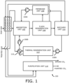
- FIG. 1 is a block diagram that illustrates a first layout of a plant 100 for reducing carbon dioxide (CO 2 ) content from a recycle gas which employs an absorption process according to an embodiment of the present disclosure.
- the plant 100 includes an absorption unit 102, a flash regeneration unit 104, a compressor 106A, liquid pumps 106B, 106N, a membrane unit 108, a recovery unit 110, a thermal regeneration unit 112, a purification unit 114, and a heat exchanger 116.
- the absorption unit 102 is configured to receive a raw synthesis gas and a lean solvent and to produce a clean synthesis gas and a laden solvent.
- the flash regeneration unit 104 is configured to flash the laden solvent received from the absorption unit 102 and generate a recycle gas including CO 2 gas and a partially laden solvent.
- the flash regeneration unit 104 implements one or more stages to produce CO 2 rich streams from the partially laden solvent, which are lean in H 2 and CO, at flash pressure levels lower than the flash pressure of the flash regeneration unit generating the recycle gas.
- a compressor 106A is configured to compress the recycle gas before directing the recycle gas to the absorption unit 102.
- the membrane unit 108 is integrated between the flash regeneration unit 104 and the compressor 106A.
- the membrane unit 108 includes a membrane and is configured to receive the recycle gas from the flash regeneration unit 104 after flashing.
- the membrane unit 108 is configured to reduce the CO 2 content in the recycle gas by permeating a CO 2 rich gas stream through the membrane to a permeate side of the membrane unit 108 and by retaining the recycle gas including a hydrogen (H 2 ) and carbon monoxide (CO) rich gas stream on a retentate side of the membrane unit 108.
- the recovery unit 110 is configured to receive the partially laden solvent from the flash regeneration unit 104 and the CO 2 rich gas stream from the membrane unit 108, and to recover the CO 2 gas from the CO 2 rich gas stream and the partially laden solvent to generate a pure CO 2 gas stream and a CO 2 -lean solvent that is depleted in CO 2 .
- the thermal regeneration unit 112 is configured to receive the CO 2 -lean solvent from the recovery unit 110 which still comprises undesired acidic components like H 2 S , to convert the CO 2 -lean solvent into the lean solvent and to produce an impure CO 2 stream also comprising the undesired acidic components.
- the lean solvent is transmitted from the thermal regeneration unit 112 to the absorption unit 102.
- the purification unit 114 is configured to receive the CO 2 gas from the flash regeneration unit 104 and the pure CO 2 gas stream from the recovery unit 110, and purify to produce a purified CO 2 gas.
- the heat exchanger 116 transfers heat between fluids passing to the thermal regeneration unit 112 from the absorption unit 102.
- the heat exchanger 116 transfers heat between the fluids passing to the absorption unit 102 from the thermal regeneration unit 112.
- the compressor 106A compresses the recycle gas including the H 2 and CO rich gas stream and transmits it to the absorption unit 102 to increase the recovery of the synthesis gas components including hydrogen (H 2 ) and carbon monoxide (CO).
- the liquid pump 106B conveys fluids from the heat exchanger 116 and transmits them to the absorption unit 102.
- the liquid pump 106N conveys fluids from the recovery unit 110 and transmits them to the thermal regeneration unit 112.
- the fluids from the recovery unit 110 may be the CO 2 -lean solvent.
- FIG. 2 is a block diagram that illustrates a second layout of a plant 200 for reducing carbon dioxide (CO 2 ) content from a recycle gas which employs a selective absorption process according to an embodiment of the present disclosure.
- the plant 200 includes a H 2 S absorption unit 202 and a CO 2 absorption unit 204 according to the selective Rectisol process, a membrane unit 206, a flash regeneration unit 208, a stripper 210, a re-absorber unit 212, a thermal regeneration unit 214, one or more compressors 216A-B, one or more liquid pumps 216C-N, and one or more heat exchangers 218A-N.
- the H 2 S absorption unit 202 is configured to receive a raw synthesis gas and a part of the CO 2 laden solvent from the CO 2 absorption unit 204 and to selectively absorb sulfur components to produce sulfur components depleted synthesis gas and a laden solvent enriched in CO 2 and sulfur components.
- the CO 2 absorption unit 204 is configured to receive sulfur components depleted synthesis gas and a lean solvent and to absorb CO 2 components to produce a clean synthesis gas and a CO 2 laden solvent enriched in CO 2 .
- the flash regeneration unit 208 is configured to flash the CO 2 laden solvent received from the CO 2 absorption unit 204 and to generate a recycle gas including CO 2 gas and a partially CO 2 laden solvent.
- the membrane unit 206 is configured to reduce the CO 2 content in the recycle gas by permeating a CO 2 rich gas stream through a membrane to a permeate side of the membrane unit 206 and by retaining the recycle gas including a hydrogen (H 2 ) and carbon monoxide (CO) rich gas stream on a retentate side of the membrane unit 206.
- the stripper 210 is configured to receive the laden solvent from the H 2 S absorption unit 202 and to produce a partially laden solvent that includes the sulfur components and which is depleted in CO 2 , and a CO 2 gas stream with a small amount of sulfur components, for example H 2 S.
- the re-absorber unit 212 is configured to receive the partially CO 2 laden solvent from the flash regeneration unit 208 and to absorb the small amount of sulfur components like H 2 S from the CO 2 gas stream produced in the stripper unit 210 and transmits the partially CO 2 laden solvent enriched in sulfur components to the stripper unit 210.
- the partially laden solvent from the stripper unit 210 that includes the sulfur components and which is depleted in CO 2 is transmitted to the thermal regeneration unit 214.
- the stripper 210 receives nitrogen (N 2 ) gas to enable CO 2 desorption from the partially laden solvent.
- the re-absorber unit 212 discharges CO 2 +N2 gas to a heat exchanger.
- the thermal regeneration unit 214 is configured to receive the partially laden solvent that comprises sulfur components and which is depleted in CO 2 from the stripper unit 210 and to produce a lean solvent and transmits the lean solvent to the CO 2 absorption unit 204.
- the thermal regeneration unit 214 receives steam for converting the partially laden solvent into the lean solvent and to produce the H 2 S offgas which contains sulfur components and the CO 2 comprised in the partially laden solvent.
- the liquid pump 216E is configured to pump a part of the partially laden solvent from the flash regeneration unit 208 to the re-absorber unit 212.
- the liquid pump 216D is configured to pump the remaining part of the partially laden solvent from the flash regeneration unit 208 to the CO 2 absorption unit 204.
- the one or more compressors 216A-B compresses any of gas flow from the membrane unit 206 to a raw gas conduit, and the gas flow from the flash regeneration unit 208 to the CO 2 product stream.
- the liquid pumps 216 F-N are configured to pump the partially laden solvent flow from the stripper 210 via one or more heat exchangers 218N, to the thermal regeneration unit 214 or to pump the leant solvent from the thermal regeneration unit 214 via one or more heat exchangers 218 N to the to the CO 2 absorption unit 202.
- heat exchanger 218A transfers heat between the gas passing to the H 2 S absorption unit 202 from the raw gas conduit.
- heat exchanger 218N transfers heat between the liquid passing to the CO 2 absorption unit 202 from the thermal regeneration unit 214 the liquid passing to the thermal regeneration unit 214 from the stripper 210.
Landscapes
- Chemical & Material Sciences (AREA)
- Engineering & Computer Science (AREA)
- Analytical Chemistry (AREA)
- General Chemical & Material Sciences (AREA)
- Oil, Petroleum & Natural Gas (AREA)
- Chemical Kinetics & Catalysis (AREA)
- Separation Using Semi-Permeable Membranes (AREA)
Abstract
A process for reducing carbon dioxide (CO2) content from a recycle gas in a plant (100, 200) is provided. The process includes providing an absorption unit (102, 202, 204) that receives a raw synthesis gas comprising the synthesis gas components hydrogen (H2), carbon monoxide (CO), and CO2, and a lean solvent, preferably comprising methanol, and that produces a clean synthesis gas and a laden solvent; providing a flash regeneration unit (104, 208) that flashes the laden solvent received from the absorption unit (102, 202, 204) to generate a recycle gas comprising H2, CO, and CO2 and a partially laden solvent; providing a compressor (106A, 216A) that compresses the recycle gas before directing the recycle gas to the absorption unit (102, 202, 204); integrating a membrane unit (108, 206) between the flash regeneration unit (104, 208) and the compressor (106A, 216A) or between the compressor (106A, 2016A) and the absorption unit (102, 202, 204), wherein the membrane unit (108, 206) comprises a CO2 selective membrane and receives the recycle gas from the flash regeneration unit (104, 208) after flashing; and reducing the CO2 content in the recycle gas by permeating a CO2 rich gas stream through the membrane to a permeate side of the membrane and retaining the recycle gas comprising a H2 and CO rich gas stream on a retentate side of the membrane.
Description
- The present disclosure relates generally to a process and plant for cleaning a raw synthesis gas by absorption with a solvent; more specifically, the present disclosure relates to a process and plant for reducing carbon dioxide (CO2) content from a recycle gas obtained in the gas cleaning process or plant, thereby improving recovery of valuable products from the recycle gas and reducing utility consumption. The present disclosure also relates to a process for recovering synthesis gas components from a recycle gas in an absorption plant.
- Typically, raw syngas or synthesis gas (syngas) contains hydrogen (H2) and carbon monoxide (CO) as primary components along with few acidic, sulfur containing or otherwise undesired components like carbon dioxide (CO2), hydrogen sulfide (H2S), carbonyl sulfide (COS) and hydrogen cyanide (HCN). For removing such undesired components, gas cleaning processes based on absorption or gas washing with suitable solvents, e. g. the Rectisol process, are well known from the prior art and are often employed processes for separating such undesired components from the syngas. Details of the Rectisol process are given in the prior art, e. g. Ullmann's Encyclopedia of Industrial Chemistry, 6th ed. (2002), Vol. 15, page 399 - 407, Chapter "Gas Production", Subchapter 5.4.2.1 "Physical Absorption Processes". A special reference is made to Fig. 46 on page 401 which shows the selective Rectisol process for separate removal and recovery of CO2 and H2S from a raw synthesis gas which is advantageous since it facilitates sulfur recovery from the H2S containing offgas.
- The Rectisol process uses cold methanol as solvent to absorb these undesired components in an absorber unit or a scrubbing unit, also termed gas washing unit. Afterwards, laden methanol, i. e. methanol containing such undesired components as mentioned above, is flashed in one or more consecutive flash vessels for solvent recovery, whereby flashed gases are obtained which comprise the undesired components. Disadvantageously, the flashed gases may include the main syngas compounds H2 and CO which should be recovered as they are valuable products and a certain amount of CO2 due to the absorption property of the methanol. Such valuable products are recovered by recompressing the flashed gases by a recompressor and routing the recompressed flashed gases as recycle gas to the absorber unit.
- Laid-open international patent application
WO 2019/242883 A1 gives an example on the processing and use of flashed gases retrieved from laden solvents in the context of a synthesis gas cleaning absorption process, seeFig. 1 : A CO2-laden solvent from a CO2 absorption stage 6 is flashed in an intermediate pressure flash vessel 50 followed by a low pressure flash vessel 55. The flashed gases are recycled to the absorber via dedicated recycle compressors 31, 34. - However, a high concentration of CO2 in the flashed gases leads to a higher volume of the recycle gas which has to be compressed; thereby a larger size of the recycle gas compressor with possibly more compression stages and a larger absorber unit are required. As the number and/or size of pieces of equipment increases, electricity consumption and other utility consumption also increases. The greater number and/or size of pieces of equipment adds thus to both the additional capital expenditure (CapEx) and the operational expenditure (OpEx).
- In one way, the electricity consumption may be reduced by partly removing the CO2 from the recycle gas. Existing approaches achieve this by either rewashing the CO2 in a medium pressure (MP) flash vessel or increasing pressure of a flash vessel. Disadvantages of such existing approaches are a higher utility consumption; additionally, more H2 and CO is reabsorbed which is undesired since it leads to lower H2 and CO recovery in the syngas accordingly.
- One common disadvantage of the existing approaches is thus the need for more and/or larger equipment and the consumption of a higher amount of electricity for recompressing the recycle gas.
- Therefore, there is a need to address the aforementioned technical drawbacks in existing technologies in reducing carbon dioxide (CO2) content from the recycle gas obtained by cleaning a raw synthesis gas by absorption with a solvent.
- The present disclosure seeks to provide an improved approach for reducing carbon dioxide (CO2) content from a flash gas recycled to an absorption unit, termed recycle gas for the purposes of this disclosure. An aim of the present disclosure is to provide a solution that overcomes at least partially the problems encountered in prior art and provide an improved process and plant for reducing the carbon dioxide (CO2) content in the flashed gases, thereby improving recovery of valuable products such as hydrogen (H2) and carbon monoxide (CO) from the flash gas recycled to an absorption unit and reducing utility consumption. The object of the present disclosure is achieved by the solutions provided in the enclosed independent claims. Advantageous implementations of the present disclosure are further defined in the enclosed dependent claims.
- According to a first aspect, the present disclosure provides a process for reducing carbon dioxide (CO2) content from a recycle gas in a plant, wherein the process comprises:
- providing an absorption unit that receives a raw synthesis gas comprising the synthesis gas components hydrogen (H2), carbon monoxide (CO), and CO2, and a lean solvent, preferably comprising methanol, and that produces a clean synthesis gas and a laden solvent;
- providing a flash regeneration unit that flashes the laden solvent received from the absorption unit to generate a recycle gas comprising H2, CO, and CO2 and a partially laden solvent;
- providing a compressor that compresses the recycle gas before directing the recycle gas back to the absorption unit;
- integrating a membrane unit between the flash regeneration unit and the compressor or between the compressor and the absorption unit, wherein the membrane unit comprises a CO2 selective membrane and receives the recycle gas from the flash regeneration unit (104, 208) after flashing; and
- reducing the CO2 content in the recycle gas by permeating a CO2 rich gas stream through the membrane to a permeate side of the membrane and retaining the recycle gas comprising a H2 and CO rich gas stream on a retentate side of the membrane.
- The process for reducing the CO2 content from the recycle gas in the plant according to present disclosure is of advantage as the recycle gas flow rate is reduced by depleting the CO2 upstream of the compressor by permeating the CO2 rich gas stream through the membrane to the permeate side of the membrane, thereby the compressor compresses a smaller volume of the recycle gas with lower electricity consumption. The size of the compressor and/or the number of compressor stages may also be reduced. Moreover, the inventive process comprises retaining the recycle gas comprising the H2 and CO rich gas stream on the retentate side of the membrane and thus increases the recovery of H2 and CO from the recycle gas. Due to integration of the membrane unit to reduce CO2 from the recycle gas, back-washing of CO2 in the flash regeneration unit becomes less important or even obsolete, thus leading to savings in solvent circulation, and also reduced utility consumption in the plant.
- According to a second aspect, the present disclosure provides a process for recovering synthesis gas components from a recycle gas in a plant, comprising:
- providing an absorption unit that receives a raw synthesis gas comprising the synthesis gas components hydrogen (H2), carbon monoxide (CO), and a lean solvent, preferably comprising methanol, and that produces a clean synthesis gas and a laden solvent;
- providing a flash regeneration unit that flashes the laden solvent received from the absorption unit to generate a recycle gas comprising H2, CO, and CO2 gas and partially laden solvent;
- providing a compressor that compresses the recycle gas before directing the recycle gas to the absorption unit;
- integrating a membrane unit between the flash regeneration unit and the compressor or between the compressor and the absorption unit, wherein the membrane unit comprises a CO2 selective membrane and receives the recycle gas from the flash regeneration unit after flashing;
- reducing the CO2 content in the recycle gas by permeating a CO2 rich gas stream through the membrane to a permeate side of the membrane and retaining the recycle gas comprising a hydrogen (H2) and carbon monoxide (CO) rich gas stream on a retentate side of the membrane; and
- compressing the recycle gas comprising the H2 and CO rich gas stream using the compressor and transmitting the compressed recycle gas to the absorption unit to increase the recovery of synthesis gas components comprising hydrogen (H2) and carbon monoxide (CO).
- The process for recovering synthesis gas components such as H2 and CO from the recycle gas in the plant according to present disclosure is of advantage in that recycle gas flow rate is reduced by depleting the CO2 upstream of the compressor by permeating the CO2 rich gas stream through the membrane to the permeate side of the membrane, thereby the compressor compresses a smaller volume of the recycle gas with lower electricity consumption. The size of the compressor and/or the number of compressor stages may also be reduced. Moreover, the process comprises retaining the recycle gas comprising H2 and CO rich gas stream on the retentate side of the membrane thus increasing the recovery of H2 and CO from the recycle gas. Due to integration of the membrane unit to reduce CO2 from the recycle gas, back-washing in the flash regeneration unit becomes less important or even obsolete, thus leading to savings in solvent circulation, and also reduces utility consumption in the plant.
- According to a third aspect, the present disclosure provides a plant for reducing carbon dioxide (CO2) content from a recycle gas, wherein the plant comprises:
- an absorption unit that is configured to receive a raw synthesis gas comprising the synthesis gas components hydrogen (H2), carbon monoxide (CO), and CO2, and a lean solvent, preferably comprising methanol, and that produces a clean synthesis gas and a laden solvent;
- a flash regeneration unit that is configured to flash the laden solvent received from the absorption unit and to generate a recycle gas comprising H2, CO, and CO2 gas and a partially laden solvent;
- a compressor that is configured to compress the recycle gas before directing the recycle gas to the absorption unit; and
- a membrane unit that is integrated between the flash regeneration unit and the compressor or between the compressor and the absorption unit, wherein the membrane unit has comprises a CO2 selective membrane and is configured to receive the recycle gas from the flash regeneration unit after flashing, wherein the membrane unit is configured to reduce the CO2 content in the recycle gas by permeating a CO2 rich gas stream through the membrane to a permeate side of the membrane unit and by retaining the recycle gas comprising a H2 and CO rich gas stream on a retentate side of the membrane.
- The plant for reducing the carbon dioxide (CO2) content from the recycle gas according to present disclosure is of advantage as the recycle gas flow rate is reduced by depleting the CO2 upstream of the compressor by permeating the CO2 rich gas stream through the membrane to the permeate side of the membrane, thereby the plant compresses a smaller volume of the recycle gas in the compressor with low electricity consumption. The size of the compressor and/or the number of compressor stages may also be reduced. Moreover, the process retaining the recycle gas comprising H2 and CO rich gas stream on the retentate side of the membrane thus, increasing the recovery of H2 and CO from the recycle gas. Due to integration of the membrane unit to obtain CO2 from the recycle gas in the plant, back-washing in the flash regeneration unit becomes less important or even obsolete, thus leading to savings in solvent circulation, and also reduces utility consumption in the plant.
- Embodiments of the present disclosure eliminate the aforementioned drawbacks in existing known approaches for reducing CO2 content in a recycling process. The advantage of the embodiments according to the present disclosure is that the embodiments enable to reduce the volume of the recycle gas to be compressed by reducing the CO2 content, such that the compressor compresses a smaller volume of the recycle gas with low electricity consumption, thereby reducing operating cost for the plant. The size of the compressor and/or the number of compressor stages may also be reduced. Also, recovery of H2 and CO from the recycle gas is increased by retaining the recycle gas comprising the H2 and CO rich gas stream on the retentate side of the membrane unit.
- Additional aspects, advantages, features, and objects of the present disclosure are made apparent from the drawings and the detailed description of the illustrative embodiments constructed in conjunction with the appended claims that follow. It will be appreciated that features of the present disclosure are susceptible to being combined in various combinations without departing from the scope of the present disclosure as defined by the appended claims.
- The summary above, as well as the following detailed description of illustrative embodiments, is better understood when read in conjunction with the appended drawings. To illustrate the present disclosure, exemplary constructions of the disclosure are shown in the drawings. However, the present disclosure is not limited to specific methods and instrumentalities disclosed herein. Moreover, those skilled in the art will understand that the drawings are not to scale. Wherever possible, the same elements have been indicated by identical numbers. Embodiments of the present disclosure will now be described, by way of example only, with reference to the following diagrams wherein:
-
FIG. 1 is a block diagram that illustrates a first layout of a plant for reducing carbon dioxide (CO2) content from a recycle gas which employs a non-selective absorption process according to an embodiment of the present disclosure; and -
FIG. 2 is a block diagram that illustrates a second layout of a plant for reducing carbon dioxide (CO2) content from a recycle gas which employs a selective absorption process according to an embodiment of the present disclosure. - The following detailed description illustrates embodiments of the present disclosure and ways in which they can be implemented. Although some modes of carrying out the present disclosure have been disclosed, those skilled in the art would recognize that other embodiments for carrying out or practicing the present disclosure are also possible.
- According to a first aspect, the present disclosure provides a process for reducing carbon dioxide (CO2) content from a recycle gas in a plant, wherein the process comprises: providing an absorption unit that receives a raw synthesis gas comprising the synthesis gas components hydrogen (H2), carbon monoxide (CO), and CO2, and a lean solvent, preferably comprising methanol, and that produces a clean synthesis gas and a laden solvent; providing a flash regeneration unit that flashes the laden solvent received from the absorption unit to generate a recycle gas comprising H2, CO, and CO2 and a partially laden solvent; providing a compressor that compresses the recycle gas before directing the recycle gas to the absorption unit; integrating a membrane unit between the flash regeneration unit and the compressor or between the compressor and the absorption unit, wherein the membrane unit comprises a CO2 selective membrane and receives the recycle gas from the flash regeneration unit after flashing; and reducing the CO2 content in the recycle gas by permeating a CO2 rich gas stream through the membrane to a permeate side of the membrane and retaining the recycle gas comprising a H2 and CO rich gas stream on a retentate side of the membrane.
- The process for reducing the CO2 content from the recycle gas in the plant according to present disclosure is of advantage as the process enables to decrease the volume of the recycle gas to be compressed by application of the membrane unit, such that the compressor compresses a smaller volume of the recycle gas with low electricity consumption, thereby reducing utility consumption in the plant and increasing the recovery of H2 and CO from the recycle gas. The size of the compressor and/or the number of compressor stages may also be reduced. Moreover, the process retaining the recycle gas comprising H2 and CO rich gas stream on the retentate side of the membrane thus, increasing the recovery of H2 and CO from the recycle gas.
- The membrane unit enables the CO2 to permeate faster, for example about 5 times faster, than the H2 and the CO leading to a reduction of the CO2 content in the retentate side of the membrane at higher pressure whereas the CO2 rich stream is obtained on the permeate side of the membrane at lower pressure.
- The membrane unit may be integrated downstream of the flash regeneration unit. The integration of a membrane unit avoids rewashing or backwashing of the CO2 in the flash regeneration unit. This leads to less required solvent and subsequent savings in operational expenditure (OPEX) in terms of electricity, cooling water and low pressure (LP) steam for solvent regeneration.
- The clean synthesis gas herein may be depleted of acid and/or undesired components such as carbon dioxide (CO2) or other acidic components like hydrogen sulfide (H2S).
- Optionally, the process comprises providing a recovery unit that receives the partially laden solvent from the flash regeneration unit and optionally at least a part of the CO2 rich gas stream from the membrane unit; and recovering, using the recovery unit, the CO2 gas from the partially laden solvent and optionally from the CO2 rich gas stream to generate a pure CO2 gas stream and a CO2-lean solvent that is depleted in CO2.
- Optionally, the recycle gas comprising the H2 and CO rich gas stream is compressed, using the compressor, and transmitted to the absorption unit to increase the recovery of synthesis gas components comprising hydrogen (H2) and carbon monoxide (CO).
- The process enables the absorption unit to maximize the recovery of the H2 gas and the CO gas from the recycle gas. The flow rate of the recycle gas is reduced by depleting the CO2 upstream of the compressor, which reduces the power demand of the compressor.
- Optionally, the process comprises implementing one or more stages on the flash regeneration unit to produce at least one CO2 rich stream from the raw synthesis gas.
- Optionally, the flash regeneration unit is a medium pressure flash regeneration unit.
- Optionally, the process comprises providing a thermal regeneration unit that receives the CO2-lean solvent from the recovery unit which still comprises undesired components, especially sulfur components like H2S; and converting, using the thermal regeneration unit, the CO2-lean solvent into the lean solvent, wherein the lean solvent is depleted in undesired components and is transmitted from the thermal regeneration unit to the absorption unit.
- Optionally, the process comprises providing a purification unit that receives the CO2 gas from the flash regeneration unit and the pure CO2 gas stream from the recovery unit and purifies the CO2 gas to produce a purified CO2 gas.
- Optionally, the process reduces solvent requirement for rewashing the CO2 in recycle gas generated in the flash regeneration unit and subsequent savings in electricity, cooling water, and flow streams for solvent regeneration.
- According to a second aspect, the present disclosure provides a process for recovering synthesis gas components from a recycle gas in a plant, comprising: providing an absorption unit that receives a raw synthesis gas comprising the synthesis gas components hydrogen (H2), carbon monoxide (CO), and a lean solvent, preferably comprising methanol, and that produces a clean synthesis gas and a laden solvent; providing a flash regeneration unit that flashes the laden solvent received from the absorption unit to generate a recycle gas comprising H2, CO, and CO2 gas and partially laden solvent; providing a compressor that compresses the recycle gas before directing the recycle gas to the absorption unit; integrating a membrane unit between the flash regeneration unit and the compressor or between the compressor and the absorption unit, wherein the membrane unit comprises a CO2 selective membrane and receives the recycle gas from the flash regeneration unit after flashing; reducing the CO2 content in the recycle gas by permeating a CO2 rich gas stream through the membrane to a permeate side of the membrane and retaining the recycle gas comprising a H2 and CO rich gas stream on a retentate side of the membrane; and compressing the recycle gas comprising the H2 and CO rich gas stream using the compressor and transmitting the compressed recycle gas to the absorption unit to increase the recovery of synthesis gas components comprising hydrogen (H2) and carbon monoxide (CO).
- The process for recovering the synthesis gas components from the recycle gas in the plant according to present disclosure is of advantage in that the process enables to decrease the volume of the recycle gas to be compressed by application of the membrane unit, such that the compressor compresses a smaller volume of the recycle gas with lower electricity consumption, thereby reducing utility consumption in the plant and increasing the recovery of H2 and CO from the recycle gas. The size of the compressor and/or the number of compressor stages may also be reduced. Moreover, the process retaining the recycle gas comprising H2 and CO rich gas stream on the retentate side of the membrane thus, increasing the recovery of H2 and CO from the recycle gas.
- Optionally, the process comprises providing a recovery that receives the partially laden solvent from the flash regeneration unit and optionally at least a part of the CO2 rich gas stream from the membrane unit; and recovering, using the recovery unit, the CO2 gas from the partially laden solvent and optionally from the CO2 rich gas stream to generate a pure CO2 gas stream and a CO2-lean solvent depleted in CO2.
- Optionally, the process comprises providing a thermal regeneration unit that receives the CO2-lean solvent from the recovery unit (110) which still comprises undesired components, especially sulfur components like H2S ; and converting, using the thermal regeneration unit, the CO2-lean solvent into a lean solvent, wherein the lean solvent is depleted in undesired components and is transmitted from the thermal regeneration unit to the absorption unit.
- According to a third aspect, the present disclosure provides a plant for reducing carbon dioxide (CO2) content from a recycle gas, wherein the plant comprises: an absorption unit that is configured to receive a raw synthesis gas comprising the synthesis gas components hydrogen (H2), carbon monoxide (CO), and CO2, and a lean solvent, preferably comprising methanol, and that produces a clean synthesis gas and a laden solvent; a flash regeneration unit that is configured to flash the laden solvent received from the absorption unit and to generate a recycle gas comprising H2, CO, and CO2 gas and a partially laden solvent; a compressor that is configured to compress the recycle gas before directing the recycle gas to the absorption unit; and a membrane unit that is integrated between the flash regeneration unit and the compressor or between the compressor and the absorption unit, wherein the membrane unit has comprises a CO2 selective membrane and is configured to receive the recycle gas from the flash regeneration unit after flashing, wherein the membrane unit is configured to reduce the CO2 content in the recycle gas by permeating a CO2 rich gas stream through the membrane to a permeate side of the membrane unit and by retaining the recycle gas comprising a H2 and CO rich gas stream on a retentate side of the membrane.
- The plant for reducing the CO2 content from the recycle gas according to present disclosure is of advantage as the process enables to decrease the volume of the recycle gas to be compressed by application of the membrane unit, such that the compressor compresses a smaller volume of the recycle gas with lower electricity consumption, thereby reducing utility consumption in the plant and increasing the recovery of H2 gas and CO gas from the recycle gas. The size of the compressor and/or the number of compressor stages may also be reduced. Moreover, the process retaining the recycle gas comprising H2 and CO rich gas stream on the retentate side of the membrane thus, increasing the recovery of H2 and CO from the recycle gas.
- Optionally, the plant comprises a recovery unit that is configured to: receive the partially laden solvent from the flash regeneration unit and optionally at least a part of the CO2 rich gas stream from the membrane unit; and recover the CO2 gas from the CO2 rich gas stream and the partially laden solvent to generate a pure CO2 gas stream and a CO2-lean solvent that is depleted in CO2.
- Optionally, the process comprises implementing one or more stages on the flash regeneration unit to produce CO2 rich streams from the partially laden solvent, which are lean in H2 and CO, at flash pressure levels lower than the flash pressure of the flash regeneration unit generating the recycle gas.
- Optionally, the plant comprises a thermal regeneration unit that is configured to: receive the CO2-lean solvent from the recovery unit which still comprises undesired components, especially sulfur components like H2S; and convert the CO2-lean solvent into a lean solvent, wherein the lean solvent is depleted in undesired components and is transmitted from the thermal regeneration unit to the absorption unit. The lean solvent may be transmitted from the thermal regeneration unit to the absorption unit.
- Optionally, the plant comprises a purification unit that is configured to receive the CO2 gas from the flash regeneration unit and the pure CO2 gas stream from the recovery unit and purify to produce a purified CO2 gas.
- Optionally, the plant enables the process to obtain the CO2 in a range of 40% to 70% in the permeate side of the membrane.
- A table below illustrates simulation results of utility consumption of a Rectisol unit using the process of the present disclosure and an existing solution. The process of the present disclosure excludes heating and cooling of the feed stream to the membrane.
Utility Unit Existing Solution Present Disclosure Comparison Electricity kWh 3419 3326 97% Cooling Water kWh 6437 6246 97% LP N2 Nm3/h 12328 12328 100% LP steam kWh 6950 6600 95% - A table below illustrates simulation results of utility consumption of a Rectisol unit with the membrane unit using the process of the present disclosure and an existing solution. The process of the present disclosure includes heating and cooling of a feed stream to the membrane.
Utility Unit Existing Solution Present Disclosure Comparison Electricity kWh 3419 3385 99% Cooling Water kWh 6437 6273 97% LP N2 Nm3/h 12328 12328 100% LP steam kWh 6950 6812 98% - The plant enables to save electricity and also reduce other utility consumption by integration of the membrane unit into the plant.
- Embodiments of the present disclosure substantially eliminate or at least partially address the aforementioned technical drawbacks in existing technologies in reducing carbon dioxide (CO2) content from the recycle gas thereby improving recovery of valuable products from the recycle gas and reducing utility consumption.
-
FIG. 1 is a block diagram that illustrates a first layout of aplant 100 for reducing carbon dioxide (CO2) content from a recycle gas which employs an absorption process according to an embodiment of the present disclosure. Theplant 100 includes anabsorption unit 102, aflash regeneration unit 104, acompressor 106A, liquid pumps 106B, 106N, amembrane unit 108, arecovery unit 110, athermal regeneration unit 112, apurification unit 114, and aheat exchanger 116. Theabsorption unit 102 is configured to receive a raw synthesis gas and a lean solvent and to produce a clean synthesis gas and a laden solvent. Theflash regeneration unit 104 is configured to flash the laden solvent received from theabsorption unit 102 and generate a recycle gas including CO2 gas and a partially laden solvent. - Optionally, the
flash regeneration unit 104 implements one or more stages to produce CO2 rich streams from the partially laden solvent, which are lean in H2 and CO, at flash pressure levels lower than the flash pressure of the flash regeneration unit generating the recycle gas. - A
compressor 106A is configured to compress the recycle gas before directing the recycle gas to theabsorption unit 102. Themembrane unit 108 is integrated between theflash regeneration unit 104 and thecompressor 106A. Themembrane unit 108 includes a membrane and is configured to receive the recycle gas from theflash regeneration unit 104 after flashing. Themembrane unit 108 is configured to reduce the CO2 content in the recycle gas by permeating a CO2 rich gas stream through the membrane to a permeate side of themembrane unit 108 and by retaining the recycle gas including a hydrogen (H2) and carbon monoxide (CO) rich gas stream on a retentate side of themembrane unit 108. Therecovery unit 110 is configured to receive the partially laden solvent from theflash regeneration unit 104 and the CO2 rich gas stream from themembrane unit 108, and to recover the CO2 gas from the CO2 rich gas stream and the partially laden solvent to generate a pure CO2 gas stream and a CO2-lean solvent that is depleted in CO2. - The
thermal regeneration unit 112 is configured to receive the CO2-lean solvent from therecovery unit 110 which still comprises undesired acidic components like H2S , to convert the CO2-lean solvent into the lean solvent and to produce an impure CO2 stream also comprising the undesired acidic components. The lean solvent is transmitted from thethermal regeneration unit 112 to theabsorption unit 102. Thepurification unit 114 is configured to receive the CO2 gas from theflash regeneration unit 104 and the pure CO2 gas stream from therecovery unit 110, and purify to produce a purified CO2 gas. Theheat exchanger 116 transfers heat between fluids passing to thethermal regeneration unit 112 from theabsorption unit 102. Optionally, theheat exchanger 116 transfers heat between the fluids passing to theabsorption unit 102 from thethermal regeneration unit 112. - Optionally, the
compressor 106A compresses the recycle gas including the H2 and CO rich gas stream and transmits it to theabsorption unit 102 to increase the recovery of the synthesis gas components including hydrogen (H2) and carbon monoxide (CO). Optionally, theliquid pump 106B conveys fluids from theheat exchanger 116 and transmits them to theabsorption unit 102. Optionally, theliquid pump 106N conveys fluids from therecovery unit 110 and transmits them to thethermal regeneration unit 112. The fluids from therecovery unit 110 may be the CO2-lean solvent. -
FIG. 2 is a block diagram that illustrates a second layout of aplant 200 for reducing carbon dioxide (CO2) content from a recycle gas which employs a selective absorption process according to an embodiment of the present disclosure. Theplant 200 includes a H2S absorption unit 202 and a CO2 absorption unit 204 according to the selective Rectisol process, amembrane unit 206, aflash regeneration unit 208, astripper 210, are-absorber unit 212, athermal regeneration unit 214, one ormore compressors 216A-B, one or more liquid pumps 216C-N, and one or more heat exchangers 218A-N. The H2S absorption unit 202 is configured to receive a raw synthesis gas and a part of the CO2 laden solvent from the CO2 absorption unit 204 and to selectively absorb sulfur components to produce sulfur components depleted synthesis gas and a laden solvent enriched in CO2 and sulfur components. The CO2 absorption unit 204 is configured to receive sulfur components depleted synthesis gas and a lean solvent and to absorb CO2 components to produce a clean synthesis gas and a CO2 laden solvent enriched in CO2. Theflash regeneration unit 208 is configured to flash the CO2 laden solvent received from the CO2 absorption unit 204 and to generate a recycle gas including CO2 gas and a partially CO2 laden solvent. Themembrane unit 206 is configured to reduce the CO2 content in the recycle gas by permeating a CO2 rich gas stream through a membrane to a permeate side of themembrane unit 206 and by retaining the recycle gas including a hydrogen (H2) and carbon monoxide (CO) rich gas stream on a retentate side of themembrane unit 206. Thestripper 210 is configured to receive the laden solvent from the H2S absorption unit 202 and to produce a partially laden solvent that includes the sulfur components and which is depleted in CO2, and a CO2 gas stream with a small amount of sulfur components, for example H2S. There-absorber unit 212 is configured to receive the partially CO2 laden solvent from theflash regeneration unit 208 and to absorb the small amount of sulfur components like H2S from the CO2 gas stream produced in thestripper unit 210 and transmits the partially CO2 laden solvent enriched in sulfur components to thestripper unit 210. The partially laden solvent from thestripper unit 210 that includes the sulfur components and which is depleted in CO2, is transmitted to thethermal regeneration unit 214. Optionally, thestripper 210 receives nitrogen (N2) gas to enable CO2 desorption from the partially laden solvent. There-absorber unit 212 discharges CO2+N2 gas to a heat exchanger. - The
thermal regeneration unit 214 is configured to receive the partially laden solvent that comprises sulfur components and which is depleted in CO2 from thestripper unit 210 and to produce a lean solvent and transmits the lean solvent to the CO2 absorption unit 204. Optionally, thethermal regeneration unit 214 receives steam for converting the partially laden solvent into the lean solvent and to produce the H2S offgas which contains sulfur components and the CO2 comprised in the partially laden solvent. - The
liquid pump 216E is configured to pump a part of the partially laden solvent from theflash regeneration unit 208 to there-absorber unit 212. Theliquid pump 216D is configured to pump the remaining part of the partially laden solvent from theflash regeneration unit 208 to the CO2 absorption unit 204. Optionally, the one ormore compressors 216A-B compresses any of gas flow from themembrane unit 206 to a raw gas conduit, and the gas flow from theflash regeneration unit 208 to the CO2 product stream. Optionally the liquid pumps 216 F-N are configured to pump the partially laden solvent flow from thestripper 210 via one ormore heat exchangers 218N, to thethermal regeneration unit 214 or to pump the leant solvent from thethermal regeneration unit 214 via one ormore heat exchangers 218 N to the to the CO2 absorption unit 202. Optionally,heat exchanger 218A transfers heat between the gas passing to the H2S absorption unit 202 from the raw gas conduit. Optionally,heat exchanger 218N transfers heat between the liquid passing to the CO2 absorption unit 202 from thethermal regeneration unit 214 the liquid passing to thethermal regeneration unit 214 from thestripper 210. - Modifications to embodiments of the present disclosure described in the foregoing are possible without departing from the scope of the present disclosure as defined by the accompanying claims. Expressions such as "including", "comprising", "incorporating", "have", "is" used to describe, and claim the present disclosure are intended to be construed in a non-exclusive manner, namely allowing for items, components or elements not explicitly described also to be present. Reference to the singular is also to be construed to relate to the plural.
Claims (13)
- A process (100, 200) for reducing the carbon dioxide (CO2) content from a recycle gas in a synthesis gas cleaning plant, wherein the process comprises:providing an absorption unit (102, 202, 204) that receives a raw synthesis gas comprising the synthesis gas components hydrogen (H2), carbon monoxide (CO), and CO2, and a lean solvent, preferably comprising methanol, and that produces a clean synthesis gas and a laden solvent;providing a flash regeneration unit (104, 208) that flashes the laden solvent received from the absorption unit (102, 202, 204) to generate a recycle gas comprising H2, CO, and CO2 and a partially laden solvent;providing a compressor (106A, 216A) that compresses the recycle gas before directing the recycle gas to the absorption unit (102, 202, 204);integrating a membrane unit (108, 206) between the flash regeneration unit (104, 208) and the compressor (106A, 216A) or between the compressor (106A, 2016A) and the absorption unit (102, 202, 204), wherein the membrane unit (108, 206) comprises a CO2 selective membrane and receives the recycle gas from the flash regeneration unit (104, 208) after flashing; andreducing the CO2 content in the recycle gas by permeating a CO2 rich gas stream through the membrane to a permeate side of the membrane and retaining the recycle gas comprising a H2 and CO rich gas stream on a retentate side of the membrane.
- The process according to claim 1, wherein the process comprises:providing a recovery unit (110, 210, 212) that receives the partially laden solvent from the flash regeneration unit (104, 208) and optionally at least a part of the CO2 rich gas stream from the membrane unit (108, 206); andrecovering, using the recovery unit (110, 210, 212), the CO2 gas from the partially laden solvent and optionally from the CO2 rich gas stream to generate a pure CO2 gas stream and a CO2-lean solvent that is depleted in CO2.
- The process according to any one of the preceding claims, wherein the recycle gas comprising the H2 and CO rich gas stream is compressed, using the compressor (106A, 216A), and transmitted to the absorption unit (102, 202, 204) to increase the recovery of synthesis gas components comprising hydrogen (H2) and carbon monoxide (CO).
- The process according to any one of the preceding claims, wherein the process comprises implementing one or more stages on the flash regeneration unit (104, 208) to produce at least one CO2 rich stream from the raw synthesis gas.
- The process according to any one of the claims 2 to 4, wherein the process comprises:providing a thermal regeneration unit (112, 214) that receives the CO2-lean solvent from the recovery unit (110, 210, 212) which still comprises undesired components, especially sulfur components like H2S; andconverting, using the thermal regeneration unit (112, 214), the CO2-lean solvent into the lean solvent, wherein the lean solvent is depleted in undesired components and is transmitted from the thermal regeneration unit (112, 214) to the absorption unit (102, 202, 204).
- The process according to any one of the preceding claims, wherein the process comprises providing a purification unit (114) that receives the CO2 gas from the flash regeneration unit (104, 208) and the pure CO2 gas stream from the recovery unit (110, 210, 212) and purifies the CO2 gas to produce a purified CO2 gas.
- A process for recovering synthesis gas components from a recycle gas in a plant (100, 200), comprising:providing an absorption unit (102, 202, 204) that receives a raw synthesis gas comprising the synthesis gas components hydrogen (H2), carbon monoxide (CO), and a lean solvent, preferably comprising methanol, and that produces a clean synthesis gas and a laden solvent;providing a flash regeneration unit (104, 208) that flashes the laden solvent received from the absorption unit (102, 202, 204) to generate a recycle gas comprising H2, CO, and CO2 gas and partially laden solvent;providing a compressor (106A, 216A) that compresses the recycle gas before directing the recycle gas to the absorption unit (102, 202, 204);integrating a membrane unit (108, 206) between the flash regeneration unit (104, 208) and the compressor (106A, 216A) or between the compressor (106A, 2016A) and the absorption unit (102, 202, 204), wherein the membrane unit (108, 206) comprises a CO2 selective membrane and receives the recycle gas from the flash regeneration unit (104, 208) after flashing;reducing the CO2 content in the recycle gas by permeating a CO2 rich gas stream through the membrane to a permeate side of the membrane and retaining the recycle gas comprising a H2 and CO rich gas stream on a retentate side of the membrane; andcompressing the recycle gas comprising the H2 and CO rich gas stream using the compressor (106A, 216A) and transmitting the compressed recycle gas to the absorption unit (102, 202, 204) to increase the recovery of synthesis gas components comprising hydrogen (H2) and carbon monoxide (CO).
- The process according to claim 7, wherein the process comprises:providing a recovery unit (110, 210, 212) that receives the partially laden solvent from the flash regeneration unit (104, 208) and optionally at least a part of the CO2 rich gas stream from the membrane unit (108, 206); andrecovering, using the recovery unit (110, 210, 212), the CO2 gas from the partially laden solvent and optionally from the CO2 rich gas stream to generate a pure CO2 gas stream and a CO2-lean solvent depleted in CO2.
- The process according to claim 8, wherein the process comprises:providing a thermal regeneration unit (112, 214) that receives the CO2-lean solvent from the recovery unit (110) which still comprises undesired components, especially sulfur components like H2S ; andconverting, using the thermal regeneration unit (112, 214), the CO2-lean solvent into a lean solvent, wherein the lean solvent is depleted in undesired components and is transmitted from the thermal regeneration unit (112, 214) to the absorption unit (102, 202, 204).
- A plant (100, 200) for reducing the carbon dioxide (CO2) content from a recycle gas in a synthesis gas cleaning plant, wherein the plant (100, 200) comprises:an absorption unit (102, 202, 204) that is configured to receive a raw synthesis gas comprising the synthesis gas components hydrogen (H2), carbon monoxide (CO), and CO2, and a lean solvent, preferably comprising methanol, and that produces a clean synthesis gas and a laden solvent;a flash regeneration unit (104, 208) that is configured to flash the laden solvent received from the absorption unit (102, 202, 204) and to generate a recycle gas comprising H2, CO, and CO2 gas and a partially laden solvent;a compressor (106A, 216A) that is configured to compress the recycle gas before directing the recycle gas to the absorption unit (102, 202, 204); anda membrane unit (108, 206) that is integrated between the flash regeneration unit (104, 208) and the compressor (106A, 216A) or between the compressor (106A, 206A) and the absorption unit (102, 202, 204), wherein the membrane unit (108, 206) has comprises a CO2 selective membrane and is configured to receive the recycle gas from the flash regeneration unit (104, 208) after flashing, wherein the membrane unit (108, 206) is configured to reduce the CO2 content in the recycle gas by permeating a CO2 rich gas stream through the membrane to a permeate side of the membrane unit (108, 206) and by retaining the recycle gas comprising a H2 and CO rich gas stream on a retentate side of the membrane (108, 206).
- The plant (100, 200) according to claim 10, wherein the plant (100, 200) comprises a recovery unit (110, 210, 212) that is configured to:receive the partially laden solvent from the flash regeneration unit (104, 208) and optionally at least a part of the CO2 rich gas stream from the membrane unit (108, 206); andrecover the CO2 gas from the CO2 rich gas stream and the partially laden solvent to generate a pure CO2 gas stream and a CO2-lean solvent that is depleted in CO2.
- The plant (100, 200) according to claim 10 or 11, wherein the plant (100, 200) comprises a thermal regeneration unit (112, 214) that is configured to:receive the CO2-lean solvent from the recovery unit (110, 210, 212) which still comprises undesired components, especially sulfur components like H2S; andconvert the CO2-lean solvent into a lean solvent, wherein the lean solvent is depleted in undesired components and is transmitted from the thermal regeneration unit (112, 214) to the absorption unit (102, 202, 204).
- The plant (100, 200) according to any one of the preceding plant claims, wherein the plant (100, 200) comprises a purification unit (114) that is configured toreceive the CO2 gas from the flash regeneration unit (104, 208) and the pure CO2 gas stream from the recovery unit (110, 210, 212), andpurify to produce a purified CO2 gas.
Priority Applications (1)
| Application Number | Priority Date | Filing Date | Title |
|---|---|---|---|
| EP22020047.1A EP4226991A1 (en) | 2022-02-10 | 2022-02-10 | Process and plant for reducing carbon dioxide (co2) content from a recycle gas |
Applications Claiming Priority (1)
| Application Number | Priority Date | Filing Date | Title |
|---|---|---|---|
| EP22020047.1A EP4226991A1 (en) | 2022-02-10 | 2022-02-10 | Process and plant for reducing carbon dioxide (co2) content from a recycle gas |
Publications (1)
| Publication Number | Publication Date |
|---|---|
| EP4226991A1 true EP4226991A1 (en) | 2023-08-16 |
Family
ID=80447683
Family Applications (1)
| Application Number | Title | Priority Date | Filing Date |
|---|---|---|---|
| EP22020047.1A Withdrawn EP4226991A1 (en) | 2022-02-10 | 2022-02-10 | Process and plant for reducing carbon dioxide (co2) content from a recycle gas |
Country Status (1)
| Country | Link |
|---|---|
| EP (1) | EP4226991A1 (en) |
Citations (2)
| Publication number | Priority date | Publication date | Assignee | Title |
|---|---|---|---|---|
| EP2141119A1 (en) * | 2007-03-29 | 2010-01-06 | Nippon Oil Corporation | Method of hydrogen production and carbon dioxide recovery and apparatus therefor |
| EP3583997A1 (en) * | 2018-06-18 | 2019-12-25 | L'air Liquide, Société Anonyme Pour L'Étude Et L'exploitation Des Procédés Georges Claude | Method and system for the production of synthesis gas |
-
2022
- 2022-02-10 EP EP22020047.1A patent/EP4226991A1/en not_active Withdrawn
Patent Citations (3)
| Publication number | Priority date | Publication date | Assignee | Title |
|---|---|---|---|---|
| EP2141119A1 (en) * | 2007-03-29 | 2010-01-06 | Nippon Oil Corporation | Method of hydrogen production and carbon dioxide recovery and apparatus therefor |
| EP3583997A1 (en) * | 2018-06-18 | 2019-12-25 | L'air Liquide, Société Anonyme Pour L'Étude Et L'exploitation Des Procédés Georges Claude | Method and system for the production of synthesis gas |
| WO2019242883A1 (en) | 2018-06-18 | 2019-12-26 | L'air Liquide, Societe Anonyme Pour L'etude Et L' Exploitation Des Procedes Georges Claude | Process and plant for purifying crude synthesis gas |
Non-Patent Citations (1)
| Title |
|---|
| "Ullmann' s Encyclopedia of Industrial Chemistry", vol. 15, 2002, pages: 399 - 407 |
Similar Documents
| Publication | Publication Date | Title |
|---|---|---|
| CN1163405C (en) | Process for simultaneous acid gas removal and hydrogen generation in a gasification power system | |
| CN100406106C (en) | Method for selectively removing hydrogen sulfide and carbon dioxide from raw fuel gas | |
| KR101518726B1 (en) | Removal of carbon dioxide from a feed gas | |
| CN101850949B (en) | Method with high purity and high recovery rate for purifying hydrogen gas in coke oven gas | |
| US8966937B2 (en) | Process for generating and separating a hydrogen-carbon monoxide mixture by cryogenic distillation | |
| CN101549856B (en) | Separation method for comprehensive recovery of hydrogen and carbon monoxide in synthetic purge gas | |
| JPS6249927A (en) | Hibrid membrane/extremely low temperature method to hydrogen purification | |
| JP2005529057A (en) | Apparatus and method for producing and separating synthesis gas from natural gas | |
| CN103571545B (en) | Method to synthesizing raw gas selective desulfurization | |
| CN107108244B (en) | Equipment and method for cryogenic purification of ammonia production and related modification methods | |
| US12109527B2 (en) | Process and apparatus for the separation of two gaseous streams each containing carbon monoxide, hydrogen and at least one acid gas | |
| WO2020079403A1 (en) | Separation of carbon monoxide from carbon monoxide/hydrogen syngas mixtures | |
| US12502638B2 (en) | Process and plant for removing carbon dioxide from synthesis gas | |
| US12076690B2 (en) | Process and plant for purifying crude synthesis gas | |
| RU2283832C2 (en) | Method for simultaneous production of ammonia and urea | |
| CN103421565A (en) | Biogas decarbonization process and device for synchronous recovery of liquid CO2 by gas membrane separation | |
| CN106861376A (en) | A method and device for producing high-purity hydrogen and carbon monoxide | |
| CN107381504B (en) | Device and method for preparing high-purity hydrogen from synthesis gas | |
| CN117466248A (en) | A process for extracting high-purity hydrogen from hydrogen-mixed natural gas with high recovery rate | |
| JP2013095727A (en) | Methane concentration method and apparatus for biogas | |
| CN207845154U (en) | Equipment for generating synthesis gas | |
| JP2005290151A (en) | Gas production method | |
| CN101417799B (en) | Method for recovering high-purity carbon monooxide from synthesis gas | |
| WO2020237564A1 (en) | Process and apparatus for the separation of a mixture of carbon monoxide, hydrogen and at least one acid gas | |
| CN214990268U (en) | Separating and purifying CO and H in synthesis gas2In a device |
Legal Events
| Date | Code | Title | Description |
|---|---|---|---|
| PUAI | Public reference made under article 153(3) epc to a published international application that has entered the european phase |
Free format text: ORIGINAL CODE: 0009012 |
|
| STAA | Information on the status of an ep patent application or granted ep patent |
Free format text: STATUS: THE APPLICATION HAS BEEN PUBLISHED |
|
| AK | Designated contracting states |
Kind code of ref document: A1 Designated state(s): AL AT BE BG CH CY CZ DE DK EE ES FI FR GB GR HR HU IE IS IT LI LT LU LV MC MK MT NL NO PL PT RO RS SE SI SK SM TR |
|
| STAA | Information on the status of an ep patent application or granted ep patent |
Free format text: STATUS: THE APPLICATION IS DEEMED TO BE WITHDRAWN |
|
| 18D | Application deemed to be withdrawn |
Effective date: 20240217 |