JP2005290151A - Gas production method - Google Patents
Gas production method Download PDFInfo
- Publication number
- JP2005290151A JP2005290151A JP2004105636A JP2004105636A JP2005290151A JP 2005290151 A JP2005290151 A JP 2005290151A JP 2004105636 A JP2004105636 A JP 2004105636A JP 2004105636 A JP2004105636 A JP 2004105636A JP 2005290151 A JP2005290151 A JP 2005290151A
- Authority
- JP
- Japan
- Prior art keywords
- gas
- carbon dioxide
- separation
- raw material
- methane
- Prior art date
- Legal status (The legal status is an assumption and is not a legal conclusion. Google has not performed a legal analysis and makes no representation as to the accuracy of the status listed.)
- Pending
Links
Images
Classifications
-
- F—MECHANICAL ENGINEERING; LIGHTING; HEATING; WEAPONS; BLASTING
- F25—REFRIGERATION OR COOLING; COMBINED HEATING AND REFRIGERATION SYSTEMS; HEAT PUMP SYSTEMS; MANUFACTURE OR STORAGE OF ICE; LIQUEFACTION SOLIDIFICATION OF GASES
- F25J—LIQUEFACTION, SOLIDIFICATION OR SEPARATION OF GASES OR GASEOUS OR LIQUEFIED GASEOUS MIXTURES BY PRESSURE AND COLD TREATMENT OR BY BRINGING THEM INTO THE SUPERCRITICAL STATE
- F25J3/00—Processes or apparatus for separating the constituents of gaseous or liquefied gaseous mixtures involving the use of liquefaction or solidification
- F25J3/02—Processes or apparatus for separating the constituents of gaseous or liquefied gaseous mixtures involving the use of liquefaction or solidification by rectification, i.e. by continuous interchange of heat and material between a vapour stream and a liquid stream
- F25J3/0204—Processes or apparatus for separating the constituents of gaseous or liquefied gaseous mixtures involving the use of liquefaction or solidification by rectification, i.e. by continuous interchange of heat and material between a vapour stream and a liquid stream characterised by the feed stream
- F25J3/0219—Refinery gas, cracking gas, coke oven gas, gaseous mixtures containing aliphatic unsaturated CnHm or gaseous mixtures of undefined nature
-
- F—MECHANICAL ENGINEERING; LIGHTING; HEATING; WEAPONS; BLASTING
- F25—REFRIGERATION OR COOLING; COMBINED HEATING AND REFRIGERATION SYSTEMS; HEAT PUMP SYSTEMS; MANUFACTURE OR STORAGE OF ICE; LIQUEFACTION SOLIDIFICATION OF GASES
- F25J—LIQUEFACTION, SOLIDIFICATION OR SEPARATION OF GASES OR GASEOUS OR LIQUEFIED GASEOUS MIXTURES BY PRESSURE AND COLD TREATMENT OR BY BRINGING THEM INTO THE SUPERCRITICAL STATE
- F25J3/00—Processes or apparatus for separating the constituents of gaseous or liquefied gaseous mixtures involving the use of liquefaction or solidification
- F25J3/02—Processes or apparatus for separating the constituents of gaseous or liquefied gaseous mixtures involving the use of liquefaction or solidification by rectification, i.e. by continuous interchange of heat and material between a vapour stream and a liquid stream
- F25J3/0228—Processes or apparatus for separating the constituents of gaseous or liquefied gaseous mixtures involving the use of liquefaction or solidification by rectification, i.e. by continuous interchange of heat and material between a vapour stream and a liquid stream characterised by the separated product stream
- F25J3/0233—Processes or apparatus for separating the constituents of gaseous or liquefied gaseous mixtures involving the use of liquefaction or solidification by rectification, i.e. by continuous interchange of heat and material between a vapour stream and a liquid stream characterised by the separated product stream separation of CnHm with 1 carbon atom or more
-
- F—MECHANICAL ENGINEERING; LIGHTING; HEATING; WEAPONS; BLASTING
- F25—REFRIGERATION OR COOLING; COMBINED HEATING AND REFRIGERATION SYSTEMS; HEAT PUMP SYSTEMS; MANUFACTURE OR STORAGE OF ICE; LIQUEFACTION SOLIDIFICATION OF GASES
- F25J—LIQUEFACTION, SOLIDIFICATION OR SEPARATION OF GASES OR GASEOUS OR LIQUEFIED GASEOUS MIXTURES BY PRESSURE AND COLD TREATMENT OR BY BRINGING THEM INTO THE SUPERCRITICAL STATE
- F25J3/00—Processes or apparatus for separating the constituents of gaseous or liquefied gaseous mixtures involving the use of liquefaction or solidification
- F25J3/02—Processes or apparatus for separating the constituents of gaseous or liquefied gaseous mixtures involving the use of liquefaction or solidification by rectification, i.e. by continuous interchange of heat and material between a vapour stream and a liquid stream
- F25J3/0228—Processes or apparatus for separating the constituents of gaseous or liquefied gaseous mixtures involving the use of liquefaction or solidification by rectification, i.e. by continuous interchange of heat and material between a vapour stream and a liquid stream characterised by the separated product stream
- F25J3/0238—Processes or apparatus for separating the constituents of gaseous or liquefied gaseous mixtures involving the use of liquefaction or solidification by rectification, i.e. by continuous interchange of heat and material between a vapour stream and a liquid stream characterised by the separated product stream separation of CnHm with 2 carbon atoms or more
-
- F—MECHANICAL ENGINEERING; LIGHTING; HEATING; WEAPONS; BLASTING
- F25—REFRIGERATION OR COOLING; COMBINED HEATING AND REFRIGERATION SYSTEMS; HEAT PUMP SYSTEMS; MANUFACTURE OR STORAGE OF ICE; LIQUEFACTION SOLIDIFICATION OF GASES
- F25J—LIQUEFACTION, SOLIDIFICATION OR SEPARATION OF GASES OR GASEOUS OR LIQUEFIED GASEOUS MIXTURES BY PRESSURE AND COLD TREATMENT OR BY BRINGING THEM INTO THE SUPERCRITICAL STATE
- F25J2200/00—Processes or apparatus using separation by rectification
- F25J2200/02—Processes or apparatus using separation by rectification in a single pressure main column system
-
- F—MECHANICAL ENGINEERING; LIGHTING; HEATING; WEAPONS; BLASTING
- F25—REFRIGERATION OR COOLING; COMBINED HEATING AND REFRIGERATION SYSTEMS; HEAT PUMP SYSTEMS; MANUFACTURE OR STORAGE OF ICE; LIQUEFACTION SOLIDIFICATION OF GASES
- F25J—LIQUEFACTION, SOLIDIFICATION OR SEPARATION OF GASES OR GASEOUS OR LIQUEFIED GASEOUS MIXTURES BY PRESSURE AND COLD TREATMENT OR BY BRINGING THEM INTO THE SUPERCRITICAL STATE
- F25J2205/00—Processes or apparatus using other separation and/or other processing means
- F25J2205/40—Processes or apparatus using other separation and/or other processing means using hybrid system, i.e. combining cryogenic and non-cryogenic separation techniques
-
- F—MECHANICAL ENGINEERING; LIGHTING; HEATING; WEAPONS; BLASTING
- F25—REFRIGERATION OR COOLING; COMBINED HEATING AND REFRIGERATION SYSTEMS; HEAT PUMP SYSTEMS; MANUFACTURE OR STORAGE OF ICE; LIQUEFACTION SOLIDIFICATION OF GASES
- F25J—LIQUEFACTION, SOLIDIFICATION OR SEPARATION OF GASES OR GASEOUS OR LIQUEFIED GASEOUS MIXTURES BY PRESSURE AND COLD TREATMENT OR BY BRINGING THEM INTO THE SUPERCRITICAL STATE
- F25J2205/00—Processes or apparatus using other separation and/or other processing means
- F25J2205/80—Processes or apparatus using other separation and/or other processing means using membrane, i.e. including a permeation step
-
- F—MECHANICAL ENGINEERING; LIGHTING; HEATING; WEAPONS; BLASTING
- F25—REFRIGERATION OR COOLING; COMBINED HEATING AND REFRIGERATION SYSTEMS; HEAT PUMP SYSTEMS; MANUFACTURE OR STORAGE OF ICE; LIQUEFACTION SOLIDIFICATION OF GASES
- F25J—LIQUEFACTION, SOLIDIFICATION OR SEPARATION OF GASES OR GASEOUS OR LIQUEFIED GASEOUS MIXTURES BY PRESSURE AND COLD TREATMENT OR BY BRINGING THEM INTO THE SUPERCRITICAL STATE
- F25J2210/00—Processes characterised by the type or other details of the feed stream
- F25J2210/12—Refinery or petrochemical off-gas
-
- Y—GENERAL TAGGING OF NEW TECHNOLOGICAL DEVELOPMENTS; GENERAL TAGGING OF CROSS-SECTIONAL TECHNOLOGIES SPANNING OVER SEVERAL SECTIONS OF THE IPC; TECHNICAL SUBJECTS COVERED BY FORMER USPC CROSS-REFERENCE ART COLLECTIONS [XRACs] AND DIGESTS
- Y02—TECHNOLOGIES OR APPLICATIONS FOR MITIGATION OR ADAPTATION AGAINST CLIMATE CHANGE
- Y02C—CAPTURE, STORAGE, SEQUESTRATION OR DISPOSAL OF GREENHOUSE GASES [GHG]
- Y02C20/00—Capture or disposal of greenhouse gases
- Y02C20/40—Capture or disposal of greenhouse gases of CO2
Landscapes
- Engineering & Computer Science (AREA)
- Physics & Mathematics (AREA)
- Mechanical Engineering (AREA)
- Thermal Sciences (AREA)
- General Engineering & Computer Science (AREA)
- Gas Separation By Absorption (AREA)
- Separation By Low-Temperature Treatments (AREA)
- Organic Low-Molecular-Weight Compounds And Preparation Thereof (AREA)
- Separation Using Semi-Permeable Membranes (AREA)
Abstract
Description
本発明は、膜分離法、吸収分離法及び蒸留分離法を組み合わせて、天然ガス、石油随伴ガスから二酸化炭素及びメタン等を含有する製品ガスと、炭化水素からなる液化ガスを製造する方法に関するものである。 The present invention relates to a method for producing a product gas containing carbon dioxide, methane, etc. from natural gas and petroleum-associated gas and a liquefied gas comprising hydrocarbons by combining a membrane separation method, an absorption separation method, and a distillation separation method. It is.
従来から、米国特許第4,140,504号明細書(特許文献1)に示されるように天然ガス、石油随伴ガス等からエタン回収プロセス等によってNGLが回収されている。このプロセスは、精留塔により炭化水素ガスを、メタンと、エタン等のメタンよりも沸点が高い炭化水素からなる液化ガスとに分離して回収するものである。この回収の際、天然ガス、石油随伴ガスに含まれる二酸化炭素は、ガス処理プラントのエタン回収設備における冷却工程及び脱メタン塔での二酸化炭素固化による機器の閉塞の原因となることからこれを防ぐため、また、製品中の二酸化炭素濃度を低減させエタン製品の製品規格を満たすため、原料ガスから二酸化炭素を分離する必要がある。 Conventionally, as shown in U.S. Pat. No. 4,140,504 (Patent Document 1), NGL is recovered from natural gas, petroleum-associated gas, or the like by an ethane recovery process or the like. In this process, hydrocarbon gas is separated and recovered into methane and liquefied gas composed of hydrocarbons having a boiling point higher than that of methane such as ethane by a rectification column. During this recovery, carbon dioxide contained in natural gas and oil-related gas is prevented from causing clogging of the equipment due to the cooling process in the ethane recovery facility of the gas processing plant and carbon dioxide solidification in the demethanizer tower. Therefore, it is necessary to separate carbon dioxide from the raw material gas in order to reduce the carbon dioxide concentration in the product and meet the product standard of ethane products.
これらのガスから二酸化炭素を分離する方法として、溶媒を用いて二酸化炭素を吸収、分離する方法が一般的に用いられている。例えば、このような方法の例としては、特開平4−64359(特許文献2)により、ドイツ国BASF社のaMDEAプロセスが提案されている。しかしながら、吸収溶媒を用いて二酸化炭素を炭化水素ガスから分離する方法は、大量の溶媒を循環させる為、吸収塔及び再生塔などの塔槽類、大容量の循環ポンプなどが必要となり、設備が大型化し経済的ではないという問題があった。また、分離された二酸化炭素は大気圧に近い条件となる為、大気に放出することが多く、硫化水素などの不純物を含む場合には、環境規制を守る為、焼却炉で燃やすなどの処理が必要であった。 As a method for separating carbon dioxide from these gases, a method for absorbing and separating carbon dioxide using a solvent is generally used. For example, as an example of such a method, Japanese Patent Laid-Open No. 4-64359 (Patent Document 2) proposes an aMDEA process of BASF Germany. However, the method of separating carbon dioxide from hydrocarbon gas using an absorbing solvent circulates a large amount of solvent, and therefore requires tower tanks such as an absorption tower and a regeneration tower, a large-capacity circulation pump, and the like. There was a problem that it was large and not economical. In addition, since the separated carbon dioxide is close to atmospheric pressure, it is often released to the atmosphere. When impurities such as hydrogen sulfide are included, treatment such as burning in an incinerator is required to comply with environmental regulations. It was necessary.
一方で二酸化炭素を分離する他の方法として、米国特許第4,659,343号(特許文献3)に代表されるように、分離膜を用いた方法が提案されている。分離膜を用いた二酸化炭素分離法は設備の小型化が可能であるという利点がある一方、吸収溶媒を用いる方法に比べて二酸化炭素の分離効率が悪く、原料ガスを所望の二酸化炭素濃度まで低下させることが困難であった。また、二酸化炭素の分離に際し、大量のメタンガスのロスが生じていた。 On the other hand, as another method for separating carbon dioxide, as represented by US Pat. No. 4,659,343 (Patent Document 3), a method using a separation membrane has been proposed. The carbon dioxide separation method using a separation membrane has the advantage that the equipment can be downsized, but the carbon dioxide separation efficiency is worse than the method using an absorbing solvent, and the raw material gas is reduced to the desired carbon dioxide concentration. It was difficult to make. In addition, a large amount of methane gas was lost during the separation of carbon dioxide.
分離膜を用いた二酸化炭素分離法において分離性能を上げる方法として、分離膜を多段にし、低圧段の分離膜出口の二酸化炭素の分離ガスを高圧段の分離膜の原料ガスにリサイクルさせることもよく行われている。しかし、この方法においても、高価なリサイクルガスコンプレッサーを必要とし、経済的ではないという問題点があった。なお、これらの問題はエタン回収プロセスに限らず、例えば、米国特許第6,601,406号明細書(特許文献4)に示されるような精留塔を用いて炭化水素ガスを、メタン及びエタンと、プロパン等のエタンよりも沸点が高い炭化水素からなる液化ガスと、を分離回収する、プロパン回収プロセス等においても発生していた。
本発明は、上記問題に鑑みなされたものであり、エタン回収プロセス又はプロパン回収プロセス等の蒸留分離法を用いた炭化水素回収プロセスにおいて、膜分離法、吸収分離法を併用することにより、設備全体を小型化し、ガス処理プラント全体として経済的なシステムを提供することを目的とする。また、膜分離法で分離した分離ガスを、エタン回収プロセス又はプロパン回収プロセス等によって分離されたメタン又はメタン・エタンガスと混合することにより、原料ガスのロスを減らし、従来の膜分離法を採用したプロセスに比べて原料コストを低くすることを目的とする。 The present invention has been made in view of the above problems, and in a hydrocarbon recovery process using a distillation separation method such as an ethane recovery process or a propane recovery process, by using a membrane separation method and an absorption separation method together, the entire equipment The purpose is to provide an economical system as a whole gas processing plant. In addition, the separation gas separated by the membrane separation method is mixed with methane or methane-ethane gas separated by the ethane recovery process or propane recovery process, thereby reducing the loss of raw material gas and adopting the conventional membrane separation method The objective is to lower the raw material cost compared to the process.
上記課題を解決するため、本発明は以下の構成を有することを特徴とする。すなわち、本発明は、少なくとも二酸化炭素、メタン及び炭素数が2以上の炭化水素を含有する原料ガスから、少なくとも二酸化炭素及びメタンを含有する製品ガスと、炭素数が2以上の炭化水素を有する液化ガスとを製造するガスの製造方法であって、
膜分離法によって、該原料ガスを、二酸化炭素が濃縮された分離ガスと、二酸化炭素が希釈された第一残留ガスとに分離する第一分離工程;
該第一残留ガスから吸収分離法によって未分離の二酸化炭素を分離し、第二残留ガスを得る第二分離工程;
該第ニ残留ガスから水分を分離した後、蒸留分離法によって未分離のメタンを分離し、炭素数が2以上の炭化水素を有する液化ガスを得る第一製造工程;
前記分離ガスと、該第一製造工程によって分離されたメタンとを混合して製品ガスを得る第二製造工程;
を有することを特徴とするガスの製造方法に関する。
In order to solve the above problems, the present invention is characterized by having the following configuration. That is, the present invention relates to a liquefaction having a product gas containing at least carbon dioxide and methane and a hydrocarbon having 2 or more carbon atoms from a raw material gas containing at least carbon dioxide, methane and hydrocarbons having 2 or more carbon atoms. A gas production method for producing gas,
A first separation step of separating the raw material gas into a separation gas enriched with carbon dioxide and a first residual gas diluted with carbon dioxide by a membrane separation method;
A second separation step of separating unseparated carbon dioxide from the first residual gas by an absorption separation method to obtain a second residual gas;
A first production step of separating water from the second residual gas and then separating unseparated methane by a distillation separation method to obtain a liquefied gas having a hydrocarbon having 2 or more carbon atoms;
A second production step of obtaining a product gas by mixing the separation gas and methane separated in the first production step;
It is related with the manufacturing method of the gas characterized by having.
ここで、「二酸化炭素が希釈された第一残留ガス」とは、膜分離法によって原料ガスから所定量の二酸化炭素が分離されるため、この分離された二酸化炭素の分だけ、第一残留ガス中の二酸化炭素量は減少し、第一残留ガス中の二酸化炭素濃度は原料ガス中の二酸化炭素濃度よりも低くなるということを表す。 Here, the “first residual gas diluted with carbon dioxide” means that a predetermined amount of carbon dioxide is separated from the raw material gas by the membrane separation method. This represents that the amount of carbon dioxide therein decreases, and the carbon dioxide concentration in the first residual gas becomes lower than the carbon dioxide concentration in the raw material gas.
また、本発明は、少なくとも二酸化炭素、メタン、エタン及び炭素数が3以上の炭化水素を含有する原料ガスから、少なくとも二酸化炭素、メタン及びエタンを含有する製品ガスと、炭素数が3以上の炭化水素を有する液化ガスとを製造するガスの製造方法であって、
膜分離法によって、該原料ガスを、二酸化炭素が濃縮された分離ガスと、二酸化炭素が希釈された第一残留ガスとに分離する第一分離工程;
該第一残留ガスから吸収分離法によって未分離の二酸化炭素を分離し、第二残留ガスを得る第二分離工程;
該第ニ残留ガスから水分を分離した後、蒸留分離法によって未分離のメタンとエタンを分離し、炭素数が3以上の炭化水素を有する液化ガスを得る第一製造工程;
前記分離ガスと該第一製造工程によって分離されたメタン及びエタンを混合して製品ガスを得る第二製造工程;
を有することを特徴とするガスの製造方法に関する。
In addition, the present invention provides a raw material gas containing at least carbon dioxide, methane, ethane and a hydrocarbon having 3 or more carbon atoms, a product gas containing at least carbon dioxide, methane and ethane, and a carbonization having 3 or more carbon atoms. A method for producing a gas for producing a liquefied gas having hydrogen, comprising:
A first separation step of separating the raw material gas into a separation gas enriched with carbon dioxide and a first residual gas diluted with carbon dioxide by a membrane separation method;
A second separation step of separating unseparated carbon dioxide from the first residual gas by an absorption separation method to obtain a second residual gas;
A first production step of separating water from the second residual gas and then separating unseparated methane and ethane by a distillation separation method to obtain a liquefied gas having a hydrocarbon having 3 or more carbon atoms;
A second production step of obtaining a product gas by mixing the separation gas with methane and ethane separated by the first production step;
The present invention relates to a gas production method characterized by comprising:
本発明によれば、二酸化炭素の分離法として膜分離法と吸収分離法を併用することにより、吸収分離法を用いた設備のみを採用した場合と比較して、設備全体を小型化し、ガス処理プラント全体として経済的なシステムを提供することが可能となる。
本発明によれば、膜分離法により分離された分離ガス(メタン及び二酸化炭素を主成分とするガス)を蒸留分離法によって分離されたメタン又はメタン・エタンと混合して製品ガスを得ることにより、原料ロスを少なくすることができる。
According to the present invention, by combining a membrane separation method and an absorption separation method as a carbon dioxide separation method, the entire facility can be downsized and gas treated as compared with the case where only the facility using the absorption separation method is employed. It becomes possible to provide an economical system as a whole plant.
According to the present invention, a separation gas separated by a membrane separation method (a gas mainly composed of methane and carbon dioxide) is mixed with methane or methane ethane separated by a distillation separation method to obtain a product gas. , Raw material loss can be reduced.
本発明は、膜分離法、吸収分離法を組み合わせることによって、小型の設備で、原料ガスから二酸化炭素を効果的に分離することができる。以下、詳細に説明する。 The present invention can effectively separate carbon dioxide from a raw material gas with a small facility by combining a membrane separation method and an absorption separation method. Details will be described below.
(膜分離法)
本発明の膜分離法は、分離膜を用いて原料ガスから二酸化炭素を分離するものである。この膜分離法によって原料ガスは二酸化炭素が濃縮された分離ガスと、二酸化炭素が希釈された第一残留ガスとに分離される。原料ガスとしては、天然ガス、石油随伴ガス等を用いることができる。また、分離膜としては、シリコーンゴム膜、ポリイミド膜、ポリエチレングリコールを多孔膜に含侵させたり、他のポリマーとブレンドあるいは共重合させた膜等を用いることができる。これらの中でも、ポリイミド膜を用いることが好ましい。ポリイミド膜は、二酸化炭素を高い分離効率で分離することができ、耐久性に優れている。ポリイミド膜としては、ポリアミドイミド膜、ビシクロ型ポリイミド膜、フッ素含有ポリイミド膜等を用いることができる。また、例えば、B−Hタイプポリイミド樹脂膜(宇部興産社製)を用いることができる。これらの分離膜はスパイラルエレメント、中空糸エレメント、キャピラリーエレメント、チューブラーエレメント、平膜エレメント状にしたものを用いることができる。
(Membrane separation method)
The membrane separation method of the present invention separates carbon dioxide from a raw material gas using a separation membrane. By this membrane separation method, the raw material gas is separated into a separation gas enriched with carbon dioxide and a first residual gas diluted with carbon dioxide. As the source gas, natural gas, petroleum-related gas, or the like can be used. As the separation membrane, a silicone rubber membrane, a polyimide membrane, a membrane in which polyethylene glycol is impregnated into a porous membrane, a membrane blended or copolymerized with another polymer, or the like can be used. Among these, it is preferable to use a polyimide film. The polyimide membrane can separate carbon dioxide with high separation efficiency and has excellent durability. As the polyimide film, a polyamideimide film, a bicyclo-type polyimide film, a fluorine-containing polyimide film, or the like can be used. Further, for example, a BH type polyimide resin film (manufactured by Ube Industries) can be used. As these separation membranes, spiral elements, hollow fiber elements, capillary elements, tubular elements, and flat membrane elements can be used.
また、膜分離法として多段式の膜分離装置を用いても良い。多段式の膜分離装置を用いることによって、膜分離法による二酸化炭素の分離効率を向上させることができ、吸収分離法で用いる分離装置をより小さくすることができる。 A multistage membrane separation apparatus may be used as the membrane separation method. By using a multistage membrane separation apparatus, the separation efficiency of carbon dioxide by the membrane separation method can be improved, and the separation apparatus used in the absorption separation method can be made smaller.
(吸収分離法)
本発明の吸収分離法は、吸収溶媒を用いて、第一残留ガス中に残留した未分離の二酸化炭素の吸収分離を行うものである。ここで行われる吸収分離法は、化学吸収法であっても物理吸収法であっても良い。
(Absorption separation method)
The absorption separation method of the present invention performs absorption separation of unseparated carbon dioxide remaining in the first residual gas using an absorption solvent. The absorption separation method performed here may be a chemical absorption method or a physical absorption method.
化学吸収法で用いる溶媒としてはエタノールアミン溶液、熱炭酸カリ溶液、NaOH水溶液等を挙げることができる。これらの吸収溶媒は、二酸化炭素の吸収効率に優れると共に、加熱等によって二酸化炭素を分離させることにより、容易に再使用することができる。化学吸収法としては、例えば、MDEA(メチルジエタノールアミン)溶液を吸収溶媒として使用するaMDEAプロセス(BASF社製)、UCARSOLを吸収溶媒に用いるAmine Guard FSプロセス(UOP社製)や熱炭酸カリ溶液を吸収溶媒に用いるBenfieldプロセス(UOP社製)等を用いることができる。 Examples of the solvent used in the chemical absorption method include ethanolamine solution, hot potassium carbonate solution, NaOH aqueous solution and the like. These absorption solvents are excellent in carbon dioxide absorption efficiency and can be easily reused by separating carbon dioxide by heating or the like. As chemical absorption methods, for example, an aMDEA process (made by BASF) using an MDEA (methyldiethanolamine) solution as an absorbing solvent, an Amine Guard FS process (made by UOP) using UCARSOL as an absorbing solvent, or a hot potassium carbonate solution are absorbed. A Benfield process (manufactured by UOP) used as a solvent can be used.
また、物理吸収法としては、ポリエチレングリコールのジメチルエーテルを吸収溶媒に用いるSelexolプロセス(UOP社製)やメタノールを吸収溶媒に用いるRectisolプロセス(Lurgi社製)を用いることができる。 In addition, as a physical absorption method, a Selexol process (manufactured by UOP) using dimethyl ether of polyethylene glycol as an absorbing solvent or a Rectisol process (manufactured by Lurgi) using methanol as an absorbing solvent can be used.
(蒸留分離法)
本発明の蒸留分離法は、吸収分離法によって二酸化炭素を分離した第二残留ガスから水分を分離した後に、メタンと炭素数が2以上の炭化水素、又は、メタン及びエタンと炭素数が3以上の炭化水素とに分離する方法である。蒸留分離法としては、沸点差を利用してガス成分を分離する公知の方法を利用することができる。すなわち、精留塔等で残留ガス中に含まれるガス成分をそれぞれの沸点まで冷却液化して気液の状態にし、分離する方法を利用することができ、例えば、エタン回収プロセス、プロパン回収プロセス等を用いることができる。
(Distillation separation method)
In the distillation separation method of the present invention, water is separated from the second residual gas from which carbon dioxide has been separated by the absorption separation method, and then methane and hydrocarbons having 2 or more carbon atoms, or methane, ethane and 3 or more carbon atoms. It is a method of separating into hydrocarbons. As the distillation separation method, a known method for separating a gas component using a difference in boiling points can be used. That is, it is possible to use a method in which the gas components contained in the residual gas are cooled and liquefied to their boiling points in a rectifying column or the like to be in a gas-liquid state and separated, for example, ethane recovery process, propane recovery process, etc. Can be used.
(ガスの製造方法)
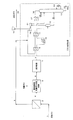
以下に、図1を用いて本発明のガス製造方法の一例を説明する。図1は、蒸留分離法としてエタン回収プロセスを用いたものである。なお、図1の記載及び図面は単に本発明の好適な態様を説明する為のものであり、本発明はこれらに限定されるものではない。
(Gas production method)
Below, an example of the gas manufacturing method of this invention is demonstrated using FIG. FIG. 1 uses an ethane recovery process as a distillation separation method. It should be noted that the description and drawings in FIG. 1 are merely for explaining preferred embodiments of the present invention, and the present invention is not limited to these.
図1のガス製造方法では、膜分離装置2にはB−Hタイプポリイミド樹脂膜(宇部興産社製)、吸収分離装置5にはaMDEAプロセス(BASF社製)の吸収溶媒を用いる。この製造方法ではまず、二酸化炭素、メタン及び炭素数が2以上の炭化水素を含有する天然ガスなどの原料ガス1は膜分離装置2に供給され、メタンを含有し二酸化炭素が濃縮された分離ガス3と、未分離の二酸化炭素、未分離のメタン及び炭素数が2以上の炭化水素を有する原料ガス(第一残留ガス)4とに分離される。原料ガス1の供給量は、必要な製品ガス及びNGL量によって異なるが、75000〜750000Nm3/hであることが好ましい(なお、Nm3は0℃、0.101MPaにおける立方メートル(m3)を表す)。
In the gas production method of FIG. 1, a BH type polyimide resin membrane (manufactured by Ube Industries) is used for the
分離膜2に供給される原料ガス1の性状としては、原料ガス中の二酸化炭素濃度が高い程、本発明の効果が顕著となるが、二酸化炭素濃度があまりに高くなりすぎると、製品ガス中の二酸化炭素濃度が高くなり、製品規格を満たさなくなるため、原料ガス1中の二酸化炭素濃度は好ましくは10モル%以上、より好ましくは20モル%以上であることが望ましい。
As the properties of the
原料ガス4中の二酸化炭素濃度は下流の溶媒循環型炭酸ガス分離設備5に必要な濃度まで下げる必要がある。この濃度は好ましくは8モル%以上、より好ましくは15モル%以上であるが、これは膜分離装置、溶媒循環装置を組み合わせたシステム全体で経済的になるように決定されることが望ましい。
The carbon dioxide concentration in the
また、原料ガス1中のメタンの濃度は、60モル%以上であることが好ましく、70モル%以上であることがより好ましい。また、90モル%以下であることが好ましく、80モル%以下であることがより好ましい。
Further, the concentration of methane in the
膜分離装置2による二酸化炭素の分離効率を上げるため、原料ガス1の圧力は高い方が好ましく、4.0MPa以上が好ましく、6.0MPa以上がより好ましい。また、分離膜における分離ガス3側の運転圧力は、後述するターボエキスパンダーが駆動するコンプレッサーの吸入圧力へ供給可能な運転圧力として決定されるが、二酸化炭素の分離効率を上げるため、低い方が好ましく、好ましくは3.0MPa以下、より好ましくは2.0MPa以下が良い。また、原料ガスの温度は10℃以上50℃以下であることが好ましい。
In order to increase the separation efficiency of carbon dioxide by the
原料ガス1中の二酸化炭素濃度と、原料ガス1の圧力がこれらの範囲内にあることによって、膜分離により効率的に二酸化炭素を分離することが可能となり、二酸化炭素の分離法として吸収分離法のみを用いた場合よりも、より設備の小型化が可能となり、経済的なコスト低減効果が大きくなる。分離膜で二酸化炭素が分離された原料ガス4は、下流にある溶媒循環型炭酸ガス分離設備(吸収分離装置)5に供給され、後工程の脱メタン塔で二酸化炭素の固化が生じない濃度(1.5〜0.2モル%以下)まで二酸化炭素が除去され、原料ガス6を得る。溶媒循環型炭酸ガス分離設備5は吸収塔であり、吸収溶媒により二酸化炭素が吸収される。二酸化炭素吸収後の溶媒は、加熱等により再生される。
Since the carbon dioxide concentration in the
溶媒循環型炭酸ガス分離設備5で二酸化炭素が分離された原料ガス6は、脱水設備7に供給され、原料ガス6中の水分が除去される。脱水設備7は、モレキュラーシーブタイプの装置である。脱水設備7で水分が除去された原料ガス8はエタン回収設備(蒸留分離装置)に供給される。このエタン回収設備としては、特許文献1記載の回収設備を用いる。エタン回収設備においては、製品ガスとの熱交換を第1原料ガスクーラー9、第2原料ガスクーラー11にて行い、プロパン冷凍による冷却を原料ガスチラー10にて行う。冷却された原料ガスは低温セパレーター12にて気液分離が行われ、ガス成分の一部はターボエキスパンダー21に供給された後、脱メタン塔13に供給される。その残りのガス成分はリフラックスサブクーラー17に供給された後、脱メタン塔13に供給される。また液成分については直接脱メタン塔13に供給される。脱メタン塔13では原料ガス8の蒸留分離が行われ、メタンを主成分とする脱メタン塔塔頂ガス16を塔頂から、またエタン、プロパン及び重質成分を主成分とするNGL(Natural Gas Liquid:天然ガス液)15を塔底から得る。
The
脱メタン塔の塔頂から取り出された脱メタン塔塔頂ガス16は原料ガスとの熱交換の後、分離膜2によって分離された二酸化炭素及びメタンを主成分とする分離ガス3と混合され、ターボエキスパンダーが駆動するコンプレッサー18に供給される。その後、製品ガスコンプレッサー19により所定の圧力まで圧縮され、製品ガス20となる。
The demethanizer
本発明の方法では、二酸化炭素が製品ガス20に混入されているが、総発熱量が製品ガス規格を満たす範囲であれば問題ない。一般的に総発熱量の規格は35.4〜42.8MJ/m3である。このように本発明では、原料ガスから効果的に二酸化炭素を分離することができる。更に、複数の工程により分離されたメタン及び二酸化炭素を混合することによって、製品ガスを得ることができ、原料ガスのロスを少なくすることができる。また、メタン及び二酸化炭素が分離された原料ガスは、NGLとして用いることができる。
In the method of the present invention, carbon dioxide is mixed in the
なお、本発明の方法は、プロパン回収プロセスに用いることもできる。すなわち、上記プロセスにおいて、蒸留分離装置としてエタン回収設備をプロパン回収設備に代えても本発明の効果を得ることができる。プロパン回収設備としては、例えば、特許文献4に示されるような設備を用いることができる。この場合、原料ガス8を得るまでは、使用する装置及び原料ガス組成等は図1のエタン回収設備の場合と同様であるが、プロパン回収設備の脱プロパン塔の塔頂からはメタン及びエタンを主成分とするガスが得られ、塔底からはプロパン及び重質成分を主成分とするNGLが得られる。そして、この塔頂ガス(メタン及びエタンを主成分とするガス)と、分離ガス3とを混合することによって製品ガス20を得る。
The method of the present invention can also be used in a propane recovery process. That is, in the above process, the effect of the present invention can be obtained even if the ethane recovery facility is replaced with a propane recovery facility as a distillation separation apparatus. As the propane recovery facility, for example, a facility as shown in
この場合、原料ガス中のメタンの濃度は、60モル%以上であることが好ましく、70モル%以上であることがより好ましい。また、90モル%以下であることが好ましく、80モル%以下であることがより好ましい。原料ガス中のエタン濃度は、10モル%以下であることが好ましい。 In this case, the concentration of methane in the raw material gas is preferably 60 mol% or more, and more preferably 70 mol% or more. Moreover, it is preferable that it is 90 mol% or less, and it is more preferable that it is 80 mol% or less. The ethane concentration in the raw material gas is preferably 10 mol% or less.
以下、本発明を実施例に基づき更に詳細に説明するが、本発明はこれに制限されるものではない。 EXAMPLES Hereinafter, although this invention is demonstrated in detail based on an Example, this invention is not restrict | limited to this.
〔実施例1〕
図1に示す装置を用いてガスを製造した。本実施例では、高圧の原料天然ガス1が6.73MPa、30℃の条件でB−Hタイプポリイミド樹脂膜(宇部興産社製)を用いた膜分離装置2に導入される。原料ガス1の組成を表1に示す。原料ガス1中の二酸化炭素濃度は10.0モル%である。この時の原料ガス組成は、表1に示される通りである。なお、表1中のCn(nは自然数)は炭素数nの炭化水素、C5+は炭素数が5以上の炭化水素を表す。また、原料天然ガス1の流量は31,694kg−mol/時(103モル/時)である。
[Example 1]
Gas was produced using the apparatus shown in FIG. In this embodiment, high-pressure raw material
このとき、膜分離装置2で分離されたガス(分離ガス3)及び精製された原料ガス(精製原料ガス4)の組成は表2に示される通りである。 At this time, the composition of the gas separated by the membrane separation apparatus 2 (separation gas 3) and the purified raw material gas (purified raw material gas 4) is as shown in Table 2.
表2の結果より、膜分離装置2により原料天然ガス1中の二酸化炭素は8.0モル%まで分離される。このとき、分離膜の全膜面積は2,100m2となる。二酸化炭素濃度8.0モル%は下流に設置される炭酸ガス吸収設備5(吸収溶媒としてメチルジエタノールアミン溶液を使用)において、加熱再生法を用いた場合に、処理可能な最大二酸化炭素濃度を想定している。このとき、分離ガス3の流量は4,142kg−mol/時(103モル/時)、精製原料ガス4の流量は27,552kg−mol/時(103モル/時)である。分離ガス側の運転圧力はターボエキスパンダーが駆動するコンプレッサーの吸入圧力により決まり、ここでは2.36MPaの条件となる。次に、精製原料ガス4は炭酸ガス吸収設備5に供給され、原料ガス4が6.5MPa、50℃の条件で吸収溶媒と接触し、脱メタン塔で二酸化炭素の固化が生じない濃度まで二酸化炭素が分離される。このとき、分離された原料ガス6は二酸化炭素を0.2モル%含んだ原料ガス6となる。その後、二酸化炭素を吸収した溶媒は再生塔に送られ、0.1MPa、120℃の条件で溶媒から二酸化炭素が分離される。
From the results in Table 2, the
次に、原料ガス6は脱水設備に供給され、モレキュラーシーブタイプの脱水装置を用いることで原料ガス6中の水分が0.1ppmまで除去される。脱水設備で水分が除去された原料ガスは、図1のエタン回収プロセスに供給される。エタン回収プロセスにおいては、製品ガスとの熱交換及びプロパン冷凍による冷却により原料ガスを低温セパレーターにおいて−45℃まで冷却し、メタンを主成分とするガスを脱メタン塔の塔頂から、エタン、プロパン及び重質成分を主成分とするNGL(Natural Gas Liquid:天然ガス液)を脱メタン塔の塔底から得る。
Next, the
脱メタン塔の塔頂から取り出されたガスは原料ガスとの熱交換の後、二酸化炭素分離膜にて分離された分離ガス3と混合して製品ガス20を製造する。このとき、混合された製品ガスの組成は表3の通りであり、流量は24,908kg−mol/時(103モル/時)である。
The gas extracted from the top of the demethanizer tower is subjected to heat exchange with the raw material gas, and then mixed with the
混合された製品ガスは、ターボエキスパンダーが駆動するコンプレッサーに供給され、2.5MPaまで昇圧される。この後、製品ガスコンプレッサーにより7.1MPaまで圧縮される。この時の製品ガスの総発熱量は38.2MJ/m3であり、製品ガスの規格の35.4〜42.8MJ/m3の総発熱量の範囲内である。 The mixed product gas is supplied to a compressor driven by a turbo expander, and the pressure is increased to 2.5 MPa. Thereafter, the product is compressed to 7.1 MPa by a product gas compressor. The total calorific value of the product gas at this time is 38.2MJ / m 3, within the scope of the total calorific value of 35.4~42.8MJ / m 3 of product gas specifications.
〔実施例2〕
本実施例では、原料ガス1の組成及び流量、炭酸ガス吸収設備5の処理条件を変えた以外は、実施例1と同様の方法によってガスの製造を行った。原料ガス1の組成を表4に示す。原料天然ガス1中の二酸化炭素濃度は20.0モル%である。なお、表4中のCn(nは自然数)は炭素数nの炭化水素、C5+は炭素数5以上の炭化水素を表す。また、原料ガスの流量は35,752kg−mol/時(103モル/時)である。
[Example 2]
In this example, the gas was produced by the same method as in Example 1 except that the composition and flow rate of the
このとき、膜分離装置2によって分離されたガス(分離ガス3)及び精製された原料ガス(精製原料ガス4)の組成は表5に示される通りである。 At this time, the composition of the gas separated by the membrane separation device 2 (separation gas 3) and the purified source gas (purified source gas 4) is as shown in Table 5.
分離膜2により、原料ガス1中の二酸化炭素は15.0モル%まで分離される。分離膜2の全膜面積は2,300m2である。この15.0モル%は、下流に設置される炭酸ガス吸収設備5において、二酸化炭素吸収後の吸収溶媒の再生法として減圧再生法及び加熱再生法を組み合わせた場合に、処理可能な最大二酸化炭素濃度を想定している。ガスの流量は、分離ガス3が6,090kg−mol/時(103モル/時)、精製原料ガス4が29,661kg−mol/時(103モル/時)である。分離ガス側の運転圧力はターボエキスパンダーが駆動するコンプレッサーの吸入圧力により決まり、ここでは2.36MPaの条件となる。
The
精製原料ガス4は次に、炭酸ガス吸収設備5に供給され、原料ガス4が6.5MPa、50℃の条件で吸収溶媒と接触し、脱メタン塔で二酸化炭素の固化が生じない濃度まで二酸化炭素が分離される。このとき、分離された原料ガスは二酸化炭素を0.2モル%含んだガスである。また、操作条件は実施例1と同様の条件とした。
The purified
次に、原料ガス6は脱水設備7に供給され、原料ガス中の水分が0.1ppmまで除去される。脱水設備で水分が除去された原料ガスは図1のエタン回収プロセスに供給される。エタン回収プロセスにおいては、製品ガスとの熱交換及びプロパン冷凍による冷却により原料ガスを低温セパレーターにおいて−45℃まで冷却し、メタンを主成分とするガスを脱メタン塔の塔頂から、エタン、プロパン及び重質成分を主成分とするNGL(Natural Gas Liquid:天然ガス液)を脱メタン塔の塔底から得る。
Next, the
脱メタン塔の塔頂から取り出された製品ガスは原料ガスとの熱交換の後、二酸化炭素分離膜にて分離された分離ガス3と混合して製品ガスを製造する。このとき、混合された製品ガスの組成を表6に示す。また、製品ガスの流量は、26,630kg−mol/時(103モル/時)である。
The product gas taken out from the top of the demethanizer tower is subjected to heat exchange with the raw material gas and then mixed with the
混合されたガスはターボエキスパンダーが駆動するコンプレッサーに供給され、2.5MPaまで昇圧される。その後、製品ガスコンプレッサーにより7.1MPaまで圧縮される。この時の製品ガスの総発熱量は35.7MJ/m3であり、製品ガスの規格の35.4〜42.8MJ/m3の総発熱量の範囲内である。 The mixed gas is supplied to a compressor driven by a turbo expander, and the pressure is increased to 2.5 MPa. Thereafter, it is compressed to 7.1 MPa by a product gas compressor. The total calorific value of the product gas at this time is 35.7MJ / m 3, within the scope of the total calorific value of 35.4~42.8MJ / m 3 of product gas specifications.
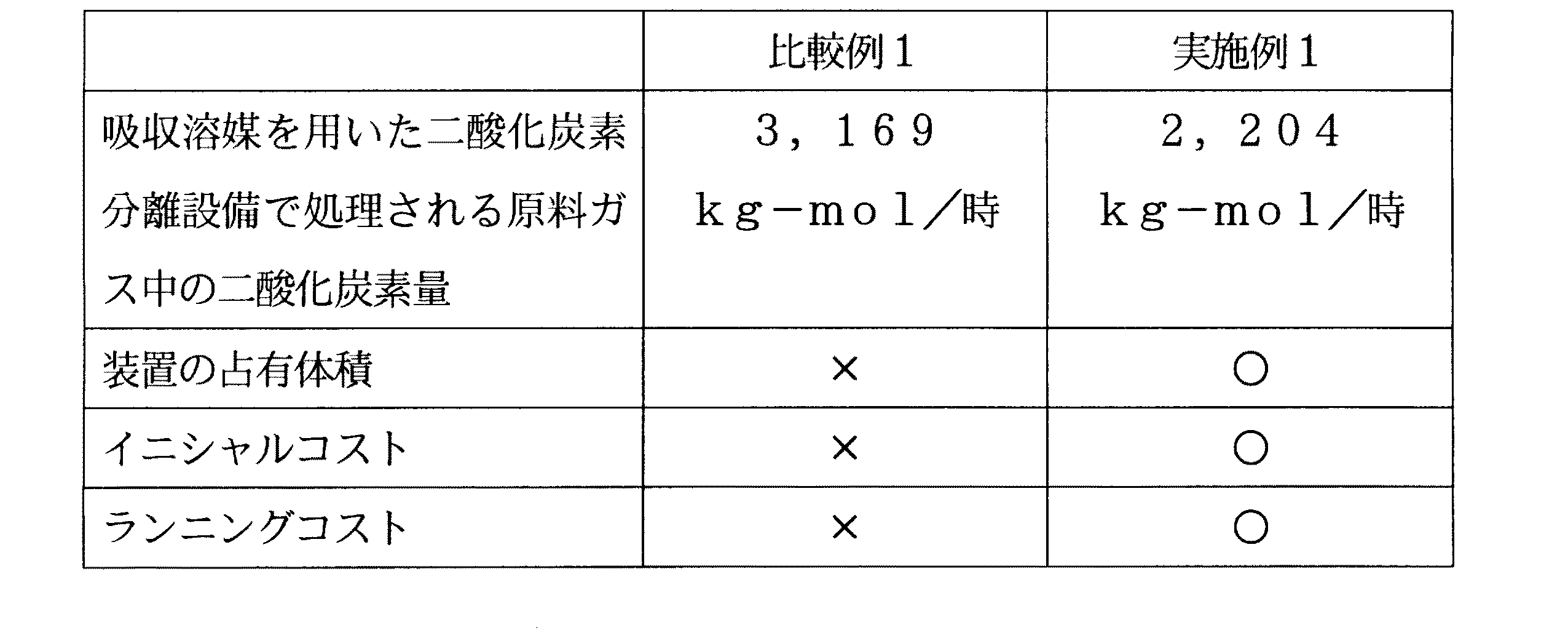
〔比較例1〕
比較例1として、膜分離法を利用せず、吸収溶媒を用いた二酸化炭素分離設備のみを使用した以外は実施例1と同様の条件で、ガスの製造を行った。吸収溶媒を用いた二酸化炭素分離設備で処理される原料ガス中の二酸化炭素量を、実施例1の結果と共に表7に示す。
[Comparative Example 1]
As Comparative Example 1, gas was produced under the same conditions as in Example 1 except that the membrane separation method was not used and only carbon dioxide separation equipment using an absorbing solvent was used. Table 7 shows the amount of carbon dioxide in the raw material gas processed by the carbon dioxide separation facility using the absorbing solvent together with the result of Example 1.
比較例1で使用した吸収溶媒を用いた二酸化炭素吸収設備としては、実施例1と同様のものを用いている。 As the carbon dioxide absorption facility using the absorption solvent used in Comparative Example 1, the same one as in Example 1 is used.
装置の占有体積:占有体積が大きく、設備費が大きい→×
占有体積が小さく、設備費が小さい→○
イニシャルコスト:大きい→×、小さい→○
ランニングコスト:大きい→×、小さい→○
表7の実施例1より、膜分離法を用いることで、吸収溶媒を用いた二酸化炭素分離設備入口での、原料ガス中の二酸化炭素濃度が大きく減少することがわかる。これは、吸収溶媒を用いた二酸化炭素分離設備の規模を小さくできることを意味し,設備費低下の効果があるといえる。一般的に膜分離膜法は、吸収溶媒を用いた二酸化炭素分離設備の設備費に比べて安価である。従って、分離膜を用いた二酸化炭素分離設備の設備費が吸収溶媒を用いた二酸化炭素分離設備の設備費低下の効果に与える影響は小さい。
Occupied volume: Large occupied volume and large equipment costs → ×
Occupied volume is small and equipment costs are small → ○
Initial cost: Large → ×, Small → ○
Running cost: large → ×, small → ○
From Example 1 of Table 7, it can be seen that by using the membrane separation method, the carbon dioxide concentration in the raw material gas at the inlet of the carbon dioxide separation facility using the absorbing solvent is greatly reduced. This means that the scale of the carbon dioxide separation facility using the absorbing solvent can be reduced, and it can be said that there is an effect of reducing the facility cost. In general, the membrane separation membrane method is cheaper than the equipment cost of carbon dioxide separation equipment using an absorbing solvent. Therefore, the influence of the equipment cost of the carbon dioxide separation equipment using the separation membrane on the effect of reducing the equipment cost of the carbon dioxide separation equipment using the absorbing solvent is small.
〔比較例2〕
比較例2として、膜分離法を使用せず、吸収溶媒を用いた二酸化炭素分離設備のみを用い、蒸留分離法としてプロパン回収設備を用いた以外は実施例1と同様の条件で、製品ガス等を製造した。実施例1とこの工程で処理されるガス量を比較した結果を表8に示す。
[Comparative Example 2]
As Comparative Example 2, product gas, etc. under the same conditions as in Example 1 except that the membrane separation method was not used, only the carbon dioxide separation facility using the absorbing solvent was used, and the propane recovery facility was used as the distillation separation method. Manufactured. Table 8 shows the result of comparison between Example 1 and the amount of gas processed in this step.
なお、表8中の装置の占有体積、イニシャルコスト、ランニングコストの評価方法は、表7と同様である。ガス量が少ないことは、プロパン回収設備自体の大きさが小さくなることを意味する。表8の実施例1より分離膜を用いた二酸化炭素分離法を用いることで、プロパン回収設備で処理されるガス量が大きく減少することがわかる。これはプロパン回収設備の大きさが小さくなることを意味し,設備費低下の効果があるといえる。 In addition, the evaluation method of the occupied volume, initial cost, and running cost of the apparatus in Table 8 is the same as that in Table 7. A small amount of gas means that the size of the propane recovery facility itself is reduced. From Example 1 of Table 8, it can be seen that the amount of gas processed in the propane recovery facility is greatly reduced by using the carbon dioxide separation method using a separation membrane. This means that the size of the propane recovery facility is reduced, and it can be said that there is an effect of lowering the equipment cost.
1 原料ガス
2 膜分離装置
3 分離ガス
4 膜分離装置で二酸化炭素が分離された原料ガス
5 溶媒循環型炭酸ガス分離設備
6 溶媒循環型炭酸ガス分離設備で二酸化炭素が分離された原料ガス
7 脱水設備
8 脱水設備で水分が除去された原料ガス
9 第1原料ガスクーラー
10 原料ガスチラー
11 第2原料ガスクーラー
12 低温セパレーター
13 脱メタン塔
14 リボイラー
15 NGL(天然ガス液)
16 脱メタン塔塔頂ガス
17 リフラックスサブクーラー
18 ターボエキスパンダーが駆動するコンプレッサー
19 製品ガスコンプレッサー
20 製品ガス
21 ターボエキスパンダー
DESCRIPTION OF
16 Demethanizer
Claims (9)
膜分離法によって、該原料ガスを、二酸化炭素が濃縮された分離ガスと、二酸化炭素が希釈された第一残留ガスとに分離する第一分離工程;
該第一残留ガスから吸収分離法によって未分離の二酸化炭素を分離し、第二残留ガスを得る第二分離工程;
該第ニ残留ガスから水分を分離した後、蒸留分離法によって未分離のメタンを分離し、炭素数が2以上の炭化水素を有する液化ガスを得る第一製造工程;
前記分離ガスと、該第一製造工程によって分離されたメタンとを混合して製品ガスを得る第二製造工程;
を有することを特徴とするガスの製造方法。 A gas for producing a product gas containing at least carbon dioxide and methane and a liquefied gas containing a hydrocarbon having two or more carbon atoms from a raw material gas containing at least carbon dioxide, methane and hydrocarbons having 2 or more carbon atoms A manufacturing method of
A first separation step of separating the raw material gas into a separation gas enriched with carbon dioxide and a first residual gas diluted with carbon dioxide by a membrane separation method;
A second separation step of separating unseparated carbon dioxide from the first residual gas by an absorption separation method to obtain a second residual gas;
A first production step for separating the water from the second residual gas and then separating unseparated methane by a distillation separation method to obtain a liquefied gas having a hydrocarbon having 2 or more carbon atoms;
A second production step of obtaining a product gas by mixing the separation gas and methane separated in the first production step;
A method for producing a gas, comprising:
膜分離法によって、該原料ガスを、二酸化炭素が濃縮された分離ガスと、二酸化炭素が希釈された第一残留ガスとに分離する第一分離工程;
該第一残留ガスから吸収分離法によって未分離の二酸化炭素を分離し、第二残留ガスを得る第二分離工程;
該第ニ残留ガスから水分を分離した後、蒸留分離法によって未分離のメタンとエタンを分離し、炭素数が3以上の炭化水素を有する液化ガスを得る第一製造工程;
前記分離ガスと該第一製造工程によって分離されたメタン及びエタンを混合して製品ガスを得る第二製造工程;
を有することを特徴とするガスの製造方法。 From a raw material gas containing at least carbon dioxide, methane, ethane and a hydrocarbon having 3 or more carbon atoms, a product gas containing at least carbon dioxide, methane and ethane, and a liquefied gas having a hydrocarbon having 3 or more carbon atoms, A gas production method for producing
A first separation step of separating the raw material gas into a separation gas enriched with carbon dioxide and a first residual gas diluted with carbon dioxide by a membrane separation method;
A second separation step of separating unseparated carbon dioxide from the first residual gas by an absorption separation method to obtain a second residual gas;
A first production step for separating the water from the second residual gas and then separating unseparated methane and ethane by a distillation separation method to obtain a liquefied gas having a hydrocarbon having 3 or more carbon atoms;
A second production step of obtaining a product gas by mixing the separation gas with methane and ethane separated by the first production step;
A method for producing a gas, comprising:
Priority Applications (1)
| Application Number | Priority Date | Filing Date | Title |
|---|---|---|---|
| JP2004105636A JP2005290151A (en) | 2004-03-31 | 2004-03-31 | Gas production method |
Applications Claiming Priority (1)
| Application Number | Priority Date | Filing Date | Title |
|---|---|---|---|
| JP2004105636A JP2005290151A (en) | 2004-03-31 | 2004-03-31 | Gas production method |
Publications (1)
| Publication Number | Publication Date |
|---|---|
| JP2005290151A true JP2005290151A (en) | 2005-10-20 |
Family
ID=35323459
Family Applications (1)
| Application Number | Title | Priority Date | Filing Date |
|---|---|---|---|
| JP2004105636A Pending JP2005290151A (en) | 2004-03-31 | 2004-03-31 | Gas production method |
Country Status (1)
| Country | Link |
|---|---|
| JP (1) | JP2005290151A (en) |
Cited By (8)
| Publication number | Priority date | Publication date | Assignee | Title |
|---|---|---|---|---|
| WO2012092980A1 (en) * | 2011-01-07 | 2012-07-12 | Statoil Petroleum As | Process for removing acid gas from natural gas |
| JP2012149002A (en) * | 2011-01-18 | 2012-08-09 | Sumitomo Heavy Industries Environment Co Ltd | Gas purifier |
| WO2013086194A1 (en) * | 2011-12-06 | 2013-06-13 | Cameron International Corporation | Floating liquefied natural gas pretreatment system |
| CN103265986A (en) * | 2013-05-30 | 2013-08-28 | 中煤能源黑龙江煤化工有限公司 | Method for extracting coal-based natural gas from methanol blowdown gas and method for producing CNG (compressed natural gas) |
| WO2017150721A1 (en) * | 2016-03-04 | 2017-09-08 | 旭化成株式会社 | Module for gas separation, and gas separation method |
| JP2017531554A (en) * | 2014-10-24 | 2017-10-26 | リサーチ トライアングル インスティテュート | Integrated system and method for removing acid gases from a gas stream |
| US10632417B2 (en) | 2018-01-23 | 2020-04-28 | Uop Llc | High hydrocarbon recovery membrane plus solvent based system |
| JP2022168949A (en) * | 2021-04-27 | 2022-11-09 | 東ソー株式会社 | Amine composition for carbon dioxide separation |
-
2004
- 2004-03-31 JP JP2004105636A patent/JP2005290151A/en active Pending
Cited By (18)
| Publication number | Priority date | Publication date | Assignee | Title |
|---|---|---|---|---|
| WO2012092980A1 (en) * | 2011-01-07 | 2012-07-12 | Statoil Petroleum As | Process for removing acid gas from natural gas |
| JP2012149002A (en) * | 2011-01-18 | 2012-08-09 | Sumitomo Heavy Industries Environment Co Ltd | Gas purifier |
| GB2510783B (en) * | 2011-12-06 | 2020-04-08 | Cameron Tech Ltd | Floating liquefied natural gas pretreatment system |
| WO2013086194A1 (en) * | 2011-12-06 | 2013-06-13 | Cameron International Corporation | Floating liquefied natural gas pretreatment system |
| GB2510783A (en) * | 2011-12-06 | 2014-08-13 | Cameron Int Corp | Floating liquefied natural gas pretreatment system |
| AU2012347752B2 (en) * | 2011-12-06 | 2017-07-20 | Cameron Technologies Limited | Floating liquefied natural gas pretreatment system |
| US11255487B2 (en) | 2011-12-06 | 2022-02-22 | Cameron International Corporation | Floating liquefied natural gas pretreatment system |
| US9791106B2 (en) | 2011-12-06 | 2017-10-17 | Cameron International Corporation | Floating liquefied natural gas pretreatment system |
| US11255486B2 (en) | 2011-12-06 | 2022-02-22 | Cameron International Corporation | Floating liquefied natural gas pretreatment system |
| CN103265986A (en) * | 2013-05-30 | 2013-08-28 | 中煤能源黑龙江煤化工有限公司 | Method for extracting coal-based natural gas from methanol blowdown gas and method for producing CNG (compressed natural gas) |
| JP2017531554A (en) * | 2014-10-24 | 2017-10-26 | リサーチ トライアングル インスティテュート | Integrated system and method for removing acid gases from a gas stream |
| JP2020179397A (en) * | 2014-10-24 | 2020-11-05 | リサーチ トライアングル インスティテュート | Integration system and method for removing acidic gas from gas flow |
| US11077405B2 (en) | 2016-03-04 | 2021-08-03 | Asahi Kasei Kabushiki Kaisha | Module for gas separation, and gas separation method |
| JPWO2017150721A1 (en) * | 2016-03-04 | 2018-10-11 | 旭化成株式会社 | Gas separation module and gas separation method |
| WO2017150721A1 (en) * | 2016-03-04 | 2017-09-08 | 旭化成株式会社 | Module for gas separation, and gas separation method |
| US10632417B2 (en) | 2018-01-23 | 2020-04-28 | Uop Llc | High hydrocarbon recovery membrane plus solvent based system |
| JP2022168949A (en) * | 2021-04-27 | 2022-11-09 | 東ソー株式会社 | Amine composition for carbon dioxide separation |
| JP7739746B2 (en) | 2021-04-27 | 2025-09-17 | 東ソー株式会社 | Amine composition for carbon dioxide separation |
Similar Documents
| Publication | Publication Date | Title |
|---|---|---|
| CA2543510C (en) | A membrane/distillation method and system for extracting co2 from hydrocarbon gas | |
| US10384160B2 (en) | Configurations and methods of high pressure acid gas removal in the production of ultra-low sulfur gas | |
| US5061465A (en) | Bulk CO2 recovery process | |
| CA2582439C (en) | Method for recovery of carbon dioxide from a gas | |
| US9114351B2 (en) | Configurations and methods for high pressure acid gas removal | |
| JP4105697B2 (en) | Acid gas removal plant and method | |
| JP4452239B2 (en) | Hydrocarbon separation method and separation apparatus | |
| DK179711B1 (en) | Separating carbon dioxide and hydrogen sulfide from a natural gas stream using co-current contacting systems | |
| AU2002307364C1 (en) | Configurations and methods for improved acid gas removal | |
| US20050000360A1 (en) | Configurations and method for improved gas removal | |
| EP2255864A1 (en) | Process for removing gaseous contaminants from a feed stream | |
| JP2016155987A (en) | System and method for separating carbon dioxide from natural gas | |
| JP2006509622A5 (en) | ||
| KR101896119B1 (en) | Method for processing a natrual load gas for obtaining a natrual processed gas and a reduction in c5+ hydrocarbons, and associated installation | |
| JP5036183B2 (en) | Improved solvent use and regeneration | |
| AU2018322435B2 (en) | Integration of cold solvent and acid gas removal | |
| CN107438475A (en) | The method of Energy Efficient recovery carbon dioxide and the equipment suitable for running this method from absorbent | |
| CN107073388B (en) | Regeneration method of energy-efficient solvent for carbon dioxide capture | |
| WO2016179154A1 (en) | Process and system for recovering natural gas liquids (ngl) from flare gas using joule-thomson (j-t) cooling and membrane separation | |
| JP2005290151A (en) | Gas production method | |
| US20240335786A1 (en) | Process for separating carbon dioxide from a raw hydrogen product | |
| CN107278167B (en) | A method of recovering carbon dioxide from an absorbent with reduced stripping steam supply | |
| AU2007201677B2 (en) | Configurations and methods for improved acid gas removal | |
| GB2365441A (en) | Enhanced natural gas liquid (NGL) recovery |