EP4226965A1 - Blutpumpe zur unterstützung der herzleistung - Google Patents
Blutpumpe zur unterstützung der herzleistung Download PDFInfo
- Publication number
- EP4226965A1 EP4226965A1 EP22020051.3A EP22020051A EP4226965A1 EP 4226965 A1 EP4226965 A1 EP 4226965A1 EP 22020051 A EP22020051 A EP 22020051A EP 4226965 A1 EP4226965 A1 EP 4226965A1
- Authority
- EP
- European Patent Office
- Prior art keywords
- housing
- pump
- blood
- impeller
- rotor
- Prior art date
- Legal status (The legal status is an assumption and is not a legal conclusion. Google has not performed a legal analysis and makes no representation as to the accuracy of the status listed.)
- Withdrawn
Links
- 239000008280 blood Substances 0.000 title claims abstract description 45
- 210000004369 blood Anatomy 0.000 title claims abstract description 45
- 230000000747 cardiac effect Effects 0.000 title claims abstract description 4
- 238000005086 pumping Methods 0.000 claims description 7
- 238000004804 winding Methods 0.000 claims description 3
- 206010019280 Heart failures Diseases 0.000 description 13
- 208000014674 injury Diseases 0.000 description 5
- 230000008733 trauma Effects 0.000 description 5
- 208000038002 heart failure with reduced ejection fraction Diseases 0.000 description 4
- 230000017531 blood circulation Effects 0.000 description 3
- 230000000694 effects Effects 0.000 description 2
- 230000002349 favourable effect Effects 0.000 description 2
- 238000002513 implantation Methods 0.000 description 2
- 230000003993 interaction Effects 0.000 description 2
- 230000002093 peripheral effect Effects 0.000 description 2
- 230000004083 survival effect Effects 0.000 description 2
- 230000000740 bleeding effect Effects 0.000 description 1
- 208000028831 congenital heart disease Diseases 0.000 description 1
- 238000010276 construction Methods 0.000 description 1
- 238000011866 long-term treatment Methods 0.000 description 1
- 210000000056 organ Anatomy 0.000 description 1
- 239000000725 suspension Substances 0.000 description 1
- 208000024891 symptom Diseases 0.000 description 1
- 238000002560 therapeutic procedure Methods 0.000 description 1
- 230000002861 ventricular Effects 0.000 description 1
Images
Classifications
-
- A—HUMAN NECESSITIES
- A61—MEDICAL OR VETERINARY SCIENCE; HYGIENE
- A61M—DEVICES FOR INTRODUCING MEDIA INTO, OR ONTO, THE BODY; DEVICES FOR TRANSDUCING BODY MEDIA OR FOR TAKING MEDIA FROM THE BODY; DEVICES FOR PRODUCING OR ENDING SLEEP OR STUPOR
- A61M60/00—Blood pumps; Devices for mechanical circulatory actuation; Balloon pumps for circulatory assistance
- A61M60/20—Type thereof
- A61M60/205—Non-positive displacement blood pumps
- A61M60/216—Non-positive displacement blood pumps including a rotating member acting on the blood, e.g. impeller
- A61M60/221—Non-positive displacement blood pumps including a rotating member acting on the blood, e.g. impeller the blood flow through the rotating member having both radial and axial components, e.g. mixed flow pumps
-
- A—HUMAN NECESSITIES
- A61—MEDICAL OR VETERINARY SCIENCE; HYGIENE
- A61M—DEVICES FOR INTRODUCING MEDIA INTO, OR ONTO, THE BODY; DEVICES FOR TRANSDUCING BODY MEDIA OR FOR TAKING MEDIA FROM THE BODY; DEVICES FOR PRODUCING OR ENDING SLEEP OR STUPOR
- A61M60/00—Blood pumps; Devices for mechanical circulatory actuation; Balloon pumps for circulatory assistance
- A61M60/80—Constructional details other than related to driving
- A61M60/802—Constructional details other than related to driving of non-positive displacement blood pumps
- A61M60/81—Pump housings
-
- A—HUMAN NECESSITIES
- A61—MEDICAL OR VETERINARY SCIENCE; HYGIENE
- A61M—DEVICES FOR INTRODUCING MEDIA INTO, OR ONTO, THE BODY; DEVICES FOR TRANSDUCING BODY MEDIA OR FOR TAKING MEDIA FROM THE BODY; DEVICES FOR PRODUCING OR ENDING SLEEP OR STUPOR
- A61M60/00—Blood pumps; Devices for mechanical circulatory actuation; Balloon pumps for circulatory assistance
- A61M60/10—Location thereof with respect to the patient's body
- A61M60/122—Implantable pumps or pumping devices, i.e. the blood being pumped inside the patient's body
-
- A—HUMAN NECESSITIES
- A61—MEDICAL OR VETERINARY SCIENCE; HYGIENE
- A61M—DEVICES FOR INTRODUCING MEDIA INTO, OR ONTO, THE BODY; DEVICES FOR TRANSDUCING BODY MEDIA OR FOR TAKING MEDIA FROM THE BODY; DEVICES FOR PRODUCING OR ENDING SLEEP OR STUPOR
- A61M60/00—Blood pumps; Devices for mechanical circulatory actuation; Balloon pumps for circulatory assistance
- A61M60/10—Location thereof with respect to the patient's body
- A61M60/122—Implantable pumps or pumping devices, i.e. the blood being pumped inside the patient's body
- A61M60/165—Implantable pumps or pumping devices, i.e. the blood being pumped inside the patient's body implantable in, on, or around the heart
- A61M60/178—Implantable pumps or pumping devices, i.e. the blood being pumped inside the patient's body implantable in, on, or around the heart drawing blood from a ventricle and returning the blood to the arterial system via a cannula external to the ventricle, e.g. left or right ventricular assist devices
-
- A—HUMAN NECESSITIES
- A61—MEDICAL OR VETERINARY SCIENCE; HYGIENE
- A61M—DEVICES FOR INTRODUCING MEDIA INTO, OR ONTO, THE BODY; DEVICES FOR TRANSDUCING BODY MEDIA OR FOR TAKING MEDIA FROM THE BODY; DEVICES FOR PRODUCING OR ENDING SLEEP OR STUPOR
- A61M60/00—Blood pumps; Devices for mechanical circulatory actuation; Balloon pumps for circulatory assistance
- A61M60/20—Type thereof
- A61M60/205—Non-positive displacement blood pumps
- A61M60/216—Non-positive displacement blood pumps including a rotating member acting on the blood, e.g. impeller
- A61M60/226—Non-positive displacement blood pumps including a rotating member acting on the blood, e.g. impeller the blood flow through the rotating member having mainly radial components
-
- A—HUMAN NECESSITIES
- A61—MEDICAL OR VETERINARY SCIENCE; HYGIENE
- A61M—DEVICES FOR INTRODUCING MEDIA INTO, OR ONTO, THE BODY; DEVICES FOR TRANSDUCING BODY MEDIA OR FOR TAKING MEDIA FROM THE BODY; DEVICES FOR PRODUCING OR ENDING SLEEP OR STUPOR
- A61M60/00—Blood pumps; Devices for mechanical circulatory actuation; Balloon pumps for circulatory assistance
- A61M60/20—Type thereof
- A61M60/205—Non-positive displacement blood pumps
- A61M60/216—Non-positive displacement blood pumps including a rotating member acting on the blood, e.g. impeller
- A61M60/226—Non-positive displacement blood pumps including a rotating member acting on the blood, e.g. impeller the blood flow through the rotating member having mainly radial components
- A61M60/232—Centrifugal pumps
-
- A—HUMAN NECESSITIES
- A61—MEDICAL OR VETERINARY SCIENCE; HYGIENE
- A61M—DEVICES FOR INTRODUCING MEDIA INTO, OR ONTO, THE BODY; DEVICES FOR TRANSDUCING BODY MEDIA OR FOR TAKING MEDIA FROM THE BODY; DEVICES FOR PRODUCING OR ENDING SLEEP OR STUPOR
- A61M60/00—Blood pumps; Devices for mechanical circulatory actuation; Balloon pumps for circulatory assistance
- A61M60/40—Details relating to driving
- A61M60/403—Details relating to driving for non-positive displacement blood pumps
- A61M60/419—Details relating to driving for non-positive displacement blood pumps the force acting on the blood contacting member being permanent magnetic, e.g. from a rotating magnetic coupling between driving and driven magnets
-
- A—HUMAN NECESSITIES
- A61—MEDICAL OR VETERINARY SCIENCE; HYGIENE
- A61M—DEVICES FOR INTRODUCING MEDIA INTO, OR ONTO, THE BODY; DEVICES FOR TRANSDUCING BODY MEDIA OR FOR TAKING MEDIA FROM THE BODY; DEVICES FOR PRODUCING OR ENDING SLEEP OR STUPOR
- A61M60/00—Blood pumps; Devices for mechanical circulatory actuation; Balloon pumps for circulatory assistance
- A61M60/40—Details relating to driving
- A61M60/403—Details relating to driving for non-positive displacement blood pumps
- A61M60/422—Details relating to driving for non-positive displacement blood pumps the force acting on the blood contacting member being electromagnetic, e.g. using canned motor pumps
-
- A—HUMAN NECESSITIES
- A61—MEDICAL OR VETERINARY SCIENCE; HYGIENE
- A61M—DEVICES FOR INTRODUCING MEDIA INTO, OR ONTO, THE BODY; DEVICES FOR TRANSDUCING BODY MEDIA OR FOR TAKING MEDIA FROM THE BODY; DEVICES FOR PRODUCING OR ENDING SLEEP OR STUPOR
- A61M60/00—Blood pumps; Devices for mechanical circulatory actuation; Balloon pumps for circulatory assistance
- A61M60/80—Constructional details other than related to driving
- A61M60/802—Constructional details other than related to driving of non-positive displacement blood pumps
- A61M60/804—Impellers
-
- A—HUMAN NECESSITIES
- A61—MEDICAL OR VETERINARY SCIENCE; HYGIENE
- A61M—DEVICES FOR INTRODUCING MEDIA INTO, OR ONTO, THE BODY; DEVICES FOR TRANSDUCING BODY MEDIA OR FOR TAKING MEDIA FROM THE BODY; DEVICES FOR PRODUCING OR ENDING SLEEP OR STUPOR
- A61M60/00—Blood pumps; Devices for mechanical circulatory actuation; Balloon pumps for circulatory assistance
- A61M60/80—Constructional details other than related to driving
- A61M60/802—Constructional details other than related to driving of non-positive displacement blood pumps
- A61M60/81—Pump housings
- A61M60/814—Volutes
-
- A—HUMAN NECESSITIES
- A61—MEDICAL OR VETERINARY SCIENCE; HYGIENE
- A61M—DEVICES FOR INTRODUCING MEDIA INTO, OR ONTO, THE BODY; DEVICES FOR TRANSDUCING BODY MEDIA OR FOR TAKING MEDIA FROM THE BODY; DEVICES FOR PRODUCING OR ENDING SLEEP OR STUPOR
- A61M60/00—Blood pumps; Devices for mechanical circulatory actuation; Balloon pumps for circulatory assistance
- A61M60/80—Constructional details other than related to driving
- A61M60/802—Constructional details other than related to driving of non-positive displacement blood pumps
- A61M60/818—Bearings
- A61M60/824—Hydrodynamic or fluid film bearings
Definitions
- the invention relates to a blood pump for supporting cardiac output, comprising a housing with a housing inlet and a housing outlet, the housing forming a first pump housing and a second pump housing, a rotor which is mounted in the housing and is rotatable about an axis, the rotor a first pump stage with a first impeller arranged in the first pump housing and a second pump stage with a second impeller arranged in the second pump housing, wherein the first and the second pump stage are each designed as a radial or diagonal pump and successively from the housing inlet to the housing outlet blood to be pumped can flow through.
- HF Heart failure
- MCS Modern mechanical circulatory support
- RBPs Rotodynamic blood pumps
- Modern implantable blood pumps are designed for adult patients suffering from heart failure of the HFrEF type, ie heart failure with reduced left ventricular ejection fraction. Such patients require implantable blood pumps that provide a comparatively high average flow (4-5 l/min). The use of such pumps in low flow applications (1-2.5 L/min) carries the risk of increased blood trauma and an increased complication rate.
- the present invention therefore aims to provide a miniaturized implantable blood pump that has the potential to reduce complications related to hemocompatibility.
- the invention is intended to address the need for a low flow blood pump for i) the pediatric heart failure population and ii) adult heart failure patients with either reduced (HFrEF) or preserved (HFpEF) ejection fraction.
- the invention essentially provides for a blood pump of the type mentioned at the outset that the first pump housing and the second pump housing are connected via a passage extending radially outward of a central portion of the housing located between the first and second pump housings.
- the middle section can be used as a rotor bearing due to the blood being guided via the external channel.
- a preferred embodiment of the invention provides that the rotor is rotatably mounted in the middle section of the housing.
- the middle section of the housing particularly preferably forms a hydrodynamic bearing with the rotor.
- the middle section is designed with a preferably cylindrical inner surface, which interacts with a cylindrical rotor surface to form the hydrodynamic bearing.
- the bearing gap is 50-150pm.
- the blood pump has two pump stages that can be flown through in series, the pressure build-up is distributed over the two stages and allows operation at up to 30% lower speeds compared to single-stage pumps.
- the channel surrounds the central section of the housing in a helical manner, with the direction of rotation of the helical shape being adapted to the direction of rotation of the rotor or the impellers.
- the helical channel may extend around the pump axis along an angle of, for example, 150-210°.
- first pump housing has an annular region (outlet housing/volute) surrounding the first impeller, from which the channel leads away tangentially.
- a streamlined discharge of the blood delivered by the pump is preferably achieved in that the second pump housing has an annular area surrounding the second impeller (outlet housing/volute), from which the housing outlet leads away tangentially.
- the second pump housing can have an inlet housing section which is spaced apart from the second impeller in the axial direction and into which the duct opens tangentially.
- a preferred embodiment provides that the rotor interacts with a stator, which surrounds the central section of the housing and has motor windings, to form an electrical motor.
- the rotor can be provided with permanent magnets.
- the pump is thus driven by an electromagnetic motor integrated around the hydrodynamic bearing area.
- the interaction of the stator with the rotor enables the rotor to be suspended axially on the basis of magnetic reluctance forces, which promotes a miniaturized realization of the blood pump.
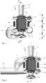
- the blood pump comprises a housing which has an inlet tube 1 converging slightly in the direction of flow 3 and an outlet 2 .
- the blood drawn in through the inlet tube 1 first passes through a first pumping stage and then through a second pumping stage.
- the first pump stage includes a first pump housing 4, in which a first impeller 5 is arranged to rotate.
- the impeller 5 drives the blood radially/diagonally outwards into an annular region 6 surrounding the first impeller 5, from which a channel 7 leads away tangentially.
- the blood reaches an inlet housing section 8 via the channel 7, from which it flows to the second pump stage, in which a second impeller 10 arranged in a second pump housing 9 rotates.
- the second impeller 10 drives the blood radially/diagonally outwards into an annular region 11 of the second pump housing 9 surrounding the second impeller 10, from which the housing outlet 2 or the outlet pipe 12 leads away tangentially.
- the first and second pumping stages are thus arranged one behind the other along the pump axis 13, with the first impeller 5 and the second impeller 10 being arranged on the same rotor 14, which is arranged in a middle section 15 of the housing arranged between the first pump housing 4 and the second pump housing 9 is mounted rotating to form a hydrodynamic bearing.
- motor windings 16 are arranged, which with the rotor 14 to form a electric motor interact. At the same time, this enables the rotor to be positioned axially on the basis of magnetic reluctance forces.
- the channel 7 connecting the first pump housing 4 and the second pump housing 9 runs radially outside of the middle section 15 of the housing.
- the axially sequential arrangement of the two pump stages in combination with a hydrodynamic bearing acting in the radial direction and a reluctance magnet suspension in the axial direction enables a miniaturized realization of the blood pump.
- the dimensions of the pump body (excluding the inlet and outlet pipe) can be about 2.5x2.5x2.5cm or less.
- a magnetic bearing or a mechanical bearing could be used instead of the hydrodynamic bearing.
Landscapes
- Health & Medical Sciences (AREA)
- Heart & Thoracic Surgery (AREA)
- Engineering & Computer Science (AREA)
- Cardiology (AREA)
- Biomedical Technology (AREA)
- Mechanical Engineering (AREA)
- Anesthesiology (AREA)
- Hematology (AREA)
- Life Sciences & Earth Sciences (AREA)
- Animal Behavior & Ethology (AREA)
- General Health & Medical Sciences (AREA)
- Public Health (AREA)
- Veterinary Medicine (AREA)
- Fluid Mechanics (AREA)
- Physics & Mathematics (AREA)
- External Artificial Organs (AREA)
Abstract
Bei einer Blutpumpe zur Unterstützung der Herzleistung, umfassend ein Gehäuse mit einem Gehäuseeinlass (1) und einem Gehäuseauslass (2), wobei das Gehäuse ein erstes Pumpengehäuse (4) und ein zweites Pumpengehäuse (9) ausbildet, einen Rotor (14) der in dem Gehäuse gelagert ist und um eine Achse (3) drehbar ist, wobei der Rotor (14) eine erste Pumpstufe mit einem in dem ersten Pumpengehäuse (4) angeordneten ersten Laufrad (5) und eine zweite Pumpstufe mit einem in dem zweiten Pumpengehäuse (9) angeordneten zweiten Laufrad (10) umfasst, wobei die erste und die zweite Pumpstufe jeweils als Radial-bzw. Diagonalpumpe ausgebildet sind und nacheinander von dem vom Gehäuseeinlass (1) zum Gehäuseauslass (2) zu pumpenden Blut durchströmbar sind, sind das erste Pumpengehäuse (4) und das zweite Pumpengehäuse (9) über einen Kanal (7) verbunden sind, der radial auberhalb eines zwischen dem ersten und dem zweiten Pumpengehäuse (4,9) angeordneten Mittelabschnitts (15) des Gehäuses verläuft.
Description
- Die Erfindung betrifft eine Blutpumpe zur Unterstützung der Herzleistung, umfassend ein Gehäuse mit einem Gehäuseeinlass und einem Gehäuseauslass, wobei das Gehäuse ein erstes Pumpengehäuse und ein zweites Pumpengehäuse ausbildet, einen Rotor der in dem Gehäuse gelagert ist und um eine Achse drehbar ist, wobei der Rotor eine erste Pumpstufe mit einem in dem ersten Pumpengehäuse angeordneten ersten Laufrad und eine zweite Pumpstufe mit einem in dem zweiten Pumpengehäuse angeordneten zweiten Laufrad umfasst, wobei die erste und die zweite Pumpstufe jeweils als Radial bzw. Diagonalpumpe ausgebildet sind und nacheinander von dem vom Gehäuseeinlass zum Gehäuseauslass zu pumpenden Blut durchströmbar sind.
- Herzinsuffizienz (HF) ist die häufigste Todesursache in den westlichen Ländern. Moderne Geräte zur mechanischen Kreislaufunterstützung (MCS) fördern das Überleben und verbessern die Lebensqualität vieler HF-Patienten. Rotodynamische Blutpumpen (RBPs) stellen die überwiegende Mehrheit der im letzten Jahrzehnt implantierten MCS-Geräte dar, wobei die Überlebensrate nach zwei Jahren über 70 % beträgt. Dennoch bleiben die klinischen Ergebnisse durch schwere Nebenwirkungen eingeschränkt, von denen die meisten durch suboptimale Interaktionen zwischen Pumpensystem und Blut hervorgerufen werden. Nur 20 % aller RBP-Empfänger bleiben ein Jahr nach der Implantation frei von lebensbedrohlichen schweren Nebenwirkungen, einschließlich Blutungen oder Schlaganfällen. Folglich ist die Lebensqualität dieser Patienten weiterhin stark eingeschränkt und die Kosteneffizienz dieser Therapie ist noch nicht erreicht.
- Moderne implantierbare Blutpumpen sind für erwachsene Patienten konzipiert, die an einer Herzinsuffizienz vom HFrEF-Typ leiden, d.h. einer Herzinsuffizienz mit reduzierter linksventrikulärer Ejektionsfraktion. Solche Patienten benötigen implantierbare Blutpumpen, die einen vergleichsweise hohen mittleren Fluss (4-5 l/min) bereitstellen. Der Einsatz solcher Pumpen in Anwendungen mit niedrigem Durchfluss (1-2,5 l/min) birgt das Risiko eines erhöhten Bluttraumas und einer erhöhten Komplikationsrate.
- Es besteht ein Bedarf an einer hämokompatiblen implantierbaren Blutpumpe, die für Patienten geeignet ist, bei denen die Pumpe einen vergleichsweise niedrigen Blutfluss bereitstellen soll. Solche Fälle umfassen:
- (i) pädiatrische HF-Patienten,
- (ii) HFrEF-Patienten mit einem geringeren Schweregrad der Herzinsuffizienz, insbesondere Herzinsuffizienz im NYHA-Stadium 3-3b, um das Fortschreiten der Symptome zu stoppen oder umzukehren,
- (iii) die große Population von HF-Patienten mit erhaltener Ejektionsfraktion (HFpEF), einer Population, für die derzeit keine andere wirksame Langzeitbehandlungsoption verfügbar ist.
- Der Artikel von Thamsen et al: "A two-stage rotary blood pump design with potentially lower blood trauma: a computational study" in Int J Artif Organs, 2016 Jun 15; 39(4):178-83, beschreibt eine zweistufige Blutpumpe zur Reduzierung von Bluttraumata bei Anwendungen, bei denen die Pumpe einen niedrigen Blutfluss bereitstellen soll. Hierbei wird der Druckaufbau auf zwei hintereinander durchströmbare Pumpenstufen aufgeteilt, was zu einer Reduktion der Umfangsgeschwindigkeiten des Impellers und somit reduzierter Blutschädigung führt.. Insbesondere bei kleinen Flüssen und vergleichsweise hohen Druckdifferenzen (niedrige spezifische Drehzahl) kann eine zweistufige Bauform zu einem effizienteren und blutschonenderen Betrieb führen. Die in Thamsen et al vorgeschlagene Ausführungsform ermöglicht jedoch keine Miniaturisierung in einem für die Implantation erforderlichen Ausmaß.
- Zusammenfassend ist festzuhalten, dass derzeit verfügbare Blutpumpen entweder zu groß für eine Implantation sind und/oder bei niedrigeren Blutflüssen ein erhöhtes Risiko für Bluttraumata und Komplikationsraten aufweisen, um Kinder bzw. Erwachsene mit weniger fortgeschrittenem Herzfehler zu versorgen. Diese Beobachtungen können dadurch erklärt werden, dass Betriebsbedingungen mit geringen Pumpendurchflüssen bei vergleichsweise hohen Drücken zu Pumpenkonstruktionen mit niedrigen spezifischen Drehzahlen führen - eine Schlüsselgröße, die anzeigt, dass diese Betriebsbedingungen mit hohen hydraulischen Wirkungsgraden nicht vereinbar sind. Folglich sind vergleichsweise hohe Leistungen erforderlich, um Druck und Strömung zu erzeugen. Diese verringerte Effizienz spiegelt sich in erhöhten Umfangsgeschwindigkeiten wider, welche wiederum zu erhöhten Bluttraumata führen können.
- Die vorliegende Erfindung zielt daher darauf ab, eine miniaturisierte implantierbare Blutpumpe zu schaffen, die das Potenzial besitzt, hämokompatibilitätsbedingte Komplikationen zu reduzieren. Insbesondere soll die Erfindung dem Bedarf einer Niedrigfluss-Blutpumpe für i) die pädiatrische Population mit Herzinsuffizienz und ii) erwachsene Patienten mit Herzinsuffizienz mit entweder reduzierter (HFrEF) oder erhaltener (HFpEF) Ejektionsfraktion Rechnung tragen.
- Zur Lösung dieser Aufgabe sieht die Erfindung bei einer Blutpumpe der eingangs genannten Art im Wesentlichen vor, dass das erste Pumpengehäuse und das zweite Pumpengehäuse über einen Kanal verbunden sind, der radial außerhalb eines zwischen dem ersten und dem zweiten Pumpengehäuse angeordneten Mittelabschnitts des Gehäuses verläuft. Dadurch, dass das von der ersten Pumpstufe zur zweiten Pumpstufe zu transportierende Blut nicht entlang des Rotors, d.h. innerhalb des Mittelabschnitts des Gehäuses geleitet wird, sondern außerhalb des Mittelabschnitts, wird eine in axialer Richtung kurze Bauweise der Blutpumpe ermöglicht. Insbesondere kann der Mittelabschnitt aufgrund der über den externen Kanal erfolgenden Blutführung als Rotorlager genutzt werden. Diesbezüglich sieht eine bevorzugte Ausbildung der Erfindung vor, dass der Rotor in dem Mittelabschnitt des Gehäuses drehbar gelagert ist. Besonders bevorzugt bildet der Mittelabschnitt des Gehäuses mit dem Rotor ein hydrodynamisches Lager aus. Der Mittelabschnitt ist hierbei mit einer bevorzugt zylindrischen Innenoberfläche ausgebildet, welche mit einer zylindrischen Rotorfläche zur Ausbildung des hydrodynamisches Lagers zusammenwirkt. Der Lagerspalt beträgt beispielsweise 50-150pm.
- Dadurch, dass die Blutpumpe zwei seriell durchströmbare Pumpstufen aufweist, wird der Druckaufbau über die zwei Stufen verteilt und erlaubt im Vergleich zu einstufigen Pumpen den Betrieb bei bis zu 30% niedrigeren Drehzahlen.
- In strömungstechnisch günstiger Weise kann vorgesehen sein, dass der Kanal den Mittelabschnitt des Gehäuses schraubenlinienförmig umgibt, wobei der Drehsinn der Schraubenlinienform an die Drehrichtung des Rotors bzw. der Laufräder angepasst ist. Der schraubenlinienförmige Kanal kann sich entlang eines Winkels von beispielsweise 150-210° um die Pumpenachse erstrecken.
- Eine strömungstechnisch günstige und platzsparende Anordnung des Kanals kann gemäß einer bevorzugten Ausbildung der Erfindung erreicht werden, wenn das erste Pumpengehäuse einen das erste Laufrad umgebenden ringförmigen Bereich (Auslassgehäuse/Volute) aufweist, von welchem der Kanal tangential wegführt.
- Eine strömungsgünstige Ableitung des von der Pumpe geförderten Bluts gelingt bevorzugt dadurch, dass das zweite Pumpengehäuse einen das zweite Laufrad umgebenden ringförmigen Bereich aufweist (Auslassgehäuse/Volute), von welchem der Gehäuseauslass tangential wegführt.
- Weiters kann das zweite Pumpengehäuse einen in axialer Richtung vom zweiten Laufrad beabstandeten Einlassgehäuseabschnitt aufweisen, in welchen der Kanal tangential einmündet.
- Hinsichtlich des elektrischen Antriebs der Blutpumpe sieht eine bevorzuge Ausbildung vor, dass der Rotor mit einem den Mittelabschnitt des Gehäuses umgebenden, Motorwicklungen aufweisenden Stator zur Ausbildung eines elektrischen Motors zusammenwirkt. Der Rotor kann hierbei mit Permanentmagneten versehen sein. Die Pumpe wird somit von einem elektromagnetischen Motor angetrieben, der um den hydrodynamischen Lagerbereich herum integriert ist. Gleichzeitig wird durch das Zusammenwirken des Stators mit dem Rotor eine axiale Aufhängung des Rotors auf Basis magnetischer Reluktanzkräfte ermöglicht, was eine miniaturisierte Realisierung der Blutpumpe begünstigt.
- Die Erfindung wird nachfolgend anhand eines in der Zeichnung schematisch dargestellten Ausführungsbeispiels näher erläutert. In dieser zeigen
Fig. 1 einen Axialschnitt einer erfindungsgemäßen Blutpumpe undFig. 2 einen Axialschnitt entlang der Linie II-II derFig. 1 . - Die Blutpumpe umfasst ein Gehäuse, das ein in Flussrichtung 3 leicht konvergierendes Einlassrohr 1 und einen Auslass 2 aufweist. Das durch das Einlassrohr 1 angesaugte Blut durchläuft zuerst eine erste Pumpstufe und danach eine zweite Pumpstufe. Die erste Pumpstufe umfasst eine erstes Pumpengehäuse 4, in dem ein erstes Laufrad 5 rotierend angeordnet ist. Das Laufrad 5 treibt das Blut radial/diagonal nach außen in einen das erste Laufrad 5 umgebenden ringförmigen Bereich 6, von welchem ein Kanal 7 tangential wegführt. Über den Kanal 7 gelangt das Blut in einen Einlassgehäuseabschnitt 8, von welchem es zur zweiten Pumpstufe fließt, in welcher ein in einem zweiten Pumpengehäuse 9 angeordnetes zweites Laufrad 10 rotiert. Das zweite Laufrad 10 treibt das Blut radial/diagonal nach außen in einen das zweite Laufrad 10 umgebenden ringförmigen Bereich 11 des zweiten Pumpengehäuses 9, von welchem der Gehäuseauslass 2 bzw. das Auslassrohr 12 tangential wegführt.
- Die erste und die zweite Pumpstufe sind somit entlang der Pumpenachse 13 hintereinander angeordnet, wobei das erste Laufrad 5 und das zweite Laufrad 10 am selben Rotor 14 angeordnet sind, der in einem zwischen dem ersten Pumpengehäuse 4 und dem zweiten Pumpengehäuse 9 angeordneten Mittelabschnitt 15 des Gehäuses unter Ausbildung eines hydrodynamischen Lagers rotierend gelagert ist. Um den Mittelabschnitt 15 des Gehäuses sind Motorwicklungen 16 angeordnet, die mit dem Rotor 14 zur Ausbildung eines elektrischen Motors zusammenwirken. Gleichzeitig wird dadurch eine axiale Positionierung des 14 Rotors auf Basis magnetischer Reluktanzkräfte ermöglicht.
- Weiters ist ersichtlich, dass der das erste Pumpengehäuse 4 und das zweite Pumpengehäuse 9 verbindende Kanal 7 radial außerhalb des Mittelabschnitts 15 des Gehäuses verläuft.
- Die axial aufeinanderfolgende Anordnung der beiden Pumpstufen in Kombination mit einem in radialer Richtung wirkenden hydrodynamischen Lager und einer Reluktanzmagnetaufhängung in axialer Richtung ermöglicht eine miniaturisierte Realisierung der Blutpumpe. Die Abmessungen des Pumpenkörpers (ohne Einlass- und Auslassrohr) können ca. 2,5x2,5x2,5cm oder weniger betragen.
- Alternativ könnte statt des hydrodynamischen Lagers ein Magnetlager oder ein mechanisches Lager verwendet werden.
Claims (8)
- Blutpumpe zur Unterstützung der Herzleistung, umfassend ein Gehäuse mit einem Gehäuseeinlass (1) und einem Gehäuseauslass (2), wobei das Gehäuse ein erstes Pumpengehäuse (4) und ein zweites Pumpengehäuse (9) ausbildet, einen Rotor (14) der in dem Gehäuse gelagert ist und um eine Achse (13) drehbar ist, wobei der Rotor (14) eine erste Pumpstufe mit einem in dem ersten Pumpengehäuse (4) angeordneten ersten Laufrad (5) und eine zweite Pumpstufe mit einem in dem zweiten Pumpengehäuse (9) angeordneten zweiten Laufrad (10) umfasst, wobei die erste und die zweite Pumpstufe jeweils als Radial- oder Diagonalpumpe ausgebildet sind und nacheinander von dem vom Gehäuseeinlass (1) zum Gehäuseauslass (2) zu pumpenden Blut durchströmbar sind, dadurch gekennzeichnet, dass das erste Pumpengehäuse (4) und das zweite Pumpengehäuse (9) über einen Kanal (7) verbunden sind, der radial außerhalb eines zwischen dem ersten und dem zweiten Pumpengehäuse (4,9) angeordneten Mittelabschnitts (15) des Gehäuses verläuft.
- Blutpumpe nach Anspruch 1, dadurch gekennzeichnet, dass der Kanal (7) den Mittelabschnitt (15) des Gehäuses schraubenlinienförmig umgibt.
- Blutpumpe nach Anspruch 1 oder 2, dadurch gekennzeichnet, dass das erste Pumpengehäuse (4) einen das erste Laufrad (5) umgebenden ringförmigen Bereich (6) aufweist, von welchem der Kanal (7) tangential wegführt.
- Blutpumpe nach Anspruch 1, 2 oder 3, dadurch gekennzeichnet, dass das zweite Pumpengehäuse (9) einen das zweite Laufrad (10) umgebenden ringförmigen Bereich (11) aufweist, von welchem der Gehäuseauslass (2) tangential wegführt.
- Blutpumpe nach einem der Ansprüche 1 bis 4, dadurch gekennzeichnet, dass das zweite Pumpengehäuse (9) einen in axialer Richtung vom zweiten Laufrad (10) beabstandeten Einlassgehäuseabschnitt (8) aufweist, in welchen der Kanal (7) tangential einmündet.
- Blutpumpe nach einem der Ansprüche 1 bis 5, dadurch gekennzeichnet, dass der Rotor (14) in dem Mittelabschnitt (15) des Gehäuses drehbar gelagert ist.
- Blutpumpe nach Anspruch 6, dadurch gekennzeichnet, dass der Mittelabschnitt (15) des Gehäuses mit dem Rotor (14) ein hydrodynamisches Lager ausbildet.
- Blutpumpe nach Anspruch 6 oder 7, dadurch gekennzeichnet, dass der Rotor (14) mit einem den Mittelabschnitt (15) des Gehäuses umgebenden, Motorwicklungen (16) aufweisenden Stator zur Ausbildung eines elektrischen Motors zusammenwirkt.
Priority Applications (4)
| Application Number | Priority Date | Filing Date | Title |
|---|---|---|---|
| EP22020051.3A EP4226965A1 (de) | 2022-02-15 | 2022-02-15 | Blutpumpe zur unterstützung der herzleistung |
| EP23706868.9A EP4479123A1 (de) | 2022-02-15 | 2023-02-15 | Blutpumpe zur unterstützung der herzleistung |
| US18/838,134 US20250144403A1 (en) | 2022-02-15 | 2023-02-15 | Blood pump for supporting cardiac performance |
| PCT/IB2023/051358 WO2023156908A1 (de) | 2022-02-15 | 2023-02-15 | Blutpumpe zur unterstützung der herzleistung |
Applications Claiming Priority (1)
| Application Number | Priority Date | Filing Date | Title |
|---|---|---|---|
| EP22020051.3A EP4226965A1 (de) | 2022-02-15 | 2022-02-15 | Blutpumpe zur unterstützung der herzleistung |
Publications (1)
| Publication Number | Publication Date |
|---|---|
| EP4226965A1 true EP4226965A1 (de) | 2023-08-16 |
Family
ID=80625539
Family Applications (2)
| Application Number | Title | Priority Date | Filing Date |
|---|---|---|---|
| EP22020051.3A Withdrawn EP4226965A1 (de) | 2022-02-15 | 2022-02-15 | Blutpumpe zur unterstützung der herzleistung |
| EP23706868.9A Pending EP4479123A1 (de) | 2022-02-15 | 2023-02-15 | Blutpumpe zur unterstützung der herzleistung |
Family Applications After (1)
| Application Number | Title | Priority Date | Filing Date |
|---|---|---|---|
| EP23706868.9A Pending EP4479123A1 (de) | 2022-02-15 | 2023-02-15 | Blutpumpe zur unterstützung der herzleistung |
Country Status (3)
| Country | Link |
|---|---|
| US (1) | US20250144403A1 (de) |
| EP (2) | EP4226965A1 (de) |
| WO (1) | WO2023156908A1 (de) |
Citations (1)
| Publication number | Priority date | Publication date | Assignee | Title |
|---|---|---|---|---|
| WO2004098677A1 (en) * | 2003-05-09 | 2004-11-18 | Queensland University Of Technology | Fluid pump |
Family Cites Families (3)
| Publication number | Priority date | Publication date | Assignee | Title |
|---|---|---|---|---|
| US4688998A (en) * | 1981-03-18 | 1987-08-25 | Olsen Don B | Magnetically suspended and rotated impellor pump apparatus and method |
| US8419609B2 (en) * | 2005-10-05 | 2013-04-16 | Heartware Inc. | Impeller for a rotary ventricular assist device |
| BR112015004141A2 (pt) * | 2012-07-02 | 2019-10-29 | Cleveland Clinic Found | Bomba de sangue rotodinâmica de duas fases |
-
2022
- 2022-02-15 EP EP22020051.3A patent/EP4226965A1/de not_active Withdrawn
-
2023
- 2023-02-15 WO PCT/IB2023/051358 patent/WO2023156908A1/de not_active Ceased
- 2023-02-15 EP EP23706868.9A patent/EP4479123A1/de active Pending
- 2023-02-15 US US18/838,134 patent/US20250144403A1/en active Pending
Patent Citations (1)
| Publication number | Priority date | Publication date | Assignee | Title |
|---|---|---|---|---|
| WO2004098677A1 (en) * | 2003-05-09 | 2004-11-18 | Queensland University Of Technology | Fluid pump |
Non-Patent Citations (1)
| Title |
|---|
| VON THAMSEN ET AL.: "A two-stage rotary blood pump design with potentially lower blood trauma: a computational study", INT J ARTIF ORGANS, vol. 39, no. 4, 15 June 2016 (2016-06-15), pages 178 - 83 |
Also Published As
| Publication number | Publication date |
|---|---|
| EP4479123A1 (de) | 2024-12-25 |
| US20250144403A1 (en) | 2025-05-08 |
| WO2023156908A1 (de) | 2023-08-24 |
Similar Documents
| Publication | Publication Date | Title |
|---|---|---|
| EP3856276B1 (de) | Gekapselte mikropumpe | |
| DE69828926T2 (de) | Dichtungslose Rotationsblutpumpe | |
| EP0786597B1 (de) | Radialgebläse | |
| EP3833410A1 (de) | Lagervorrichtung für ein herzunterstützungssystem und verfahren zum spülen eines zwischenraums in einer lagervorrichtung für ein herzunterstützungssystem | |
| EP0907386A1 (de) | Blutpumpe | |
| EP1013294B1 (de) | Diagonalflusspumpe | |
| WO1998004834A1 (de) | Zentrifugalpumpe zur förderung von blut und anderen scherempfindlichen flüssigkeiten | |
| EP0459497B1 (de) | Axiallüfter mit zylindrischem Aussengehäuse | |
| DE20004136U1 (de) | Blutpumpe | |
| DE2246265A1 (de) | Pumpe mit taumelbarem laeufer | |
| WO2001036826A1 (de) | Schnelllaufende turbopumpe | |
| EP3475577A1 (de) | Schaufelrad und kreiselpumpe damit | |
| DE19626224A1 (de) | Blutpumpe nach dem Rotationspumpenprinzip | |
| WO1999015793A1 (de) | Compoundpumpe | |
| EP0363503A1 (de) | Pumpenstufe für eine Hochvakuumpumpe | |
| EP4479123A1 (de) | Blutpumpe zur unterstützung der herzleistung | |
| DE2409857B2 (de) | Turbomolekularvakuumpumpe mit zumindest teilweise glockenfoermig ausgebildetem rotor | |
| DE102024106201A1 (de) | System mit einer Blutpumpe und einer Steuereinheit sowie Verfahren zum Betrieb einer Blutpumpe | |
| EP4325061A1 (de) | Turbomolekularvakuumpumpe | |
| EP3967881B1 (de) | Pumpe | |
| EP4285030A1 (de) | RADIALSTRÖMUNGSMASCHINE MIT KÜHLUNG UND SCHMIERUNG DURCH EIN DURCH DIE MASCHINE FLIEßENDES MEDIUM | |
| DE897469C (de) | Schleuderverdichter fuer sehr hohes Stufendruckverhaeltnis | |
| DE1528826A1 (de) | Kreiselpumpe | |
| DE69107330T2 (de) | Geräuscharme Kreiselmotorpumpe für Flüssigkeiten. | |
| DE10019820C2 (de) | Pumpe, insbesondere Umwälzpumpe für Haushaltsmaschinen wie Geschirrspülmaschinen |
Legal Events
| Date | Code | Title | Description |
|---|---|---|---|
| PUAI | Public reference made under article 153(3) epc to a published international application that has entered the european phase |
Free format text: ORIGINAL CODE: 0009012 |
|
| STAA | Information on the status of an ep patent application or granted ep patent |
Free format text: STATUS: THE APPLICATION HAS BEEN PUBLISHED |
|
| AK | Designated contracting states |
Kind code of ref document: A1 Designated state(s): AL AT BE BG CH CY CZ DE DK EE ES FI FR GB GR HR HU IE IS IT LI LT LU LV MC MK MT NL NO PL PT RO RS SE SI SK SM TR |
|
| STAA | Information on the status of an ep patent application or granted ep patent |
Free format text: STATUS: THE APPLICATION IS DEEMED TO BE WITHDRAWN |
|
| 18D | Application deemed to be withdrawn |
Effective date: 20240217 |