EP4226806B1 - Dispositif de réglage de la longueur d'un bracelet - Google Patents
Dispositif de réglage de la longueur d'un bracelet Download PDFInfo
- Publication number
- EP4226806B1 EP4226806B1 EP22156512.0A EP22156512A EP4226806B1 EP 4226806 B1 EP4226806 B1 EP 4226806B1 EP 22156512 A EP22156512 A EP 22156512A EP 4226806 B1 EP4226806 B1 EP 4226806B1
- Authority
- EP
- European Patent Office
- Prior art keywords
- cover
- bracelet
- indexing
- length
- fixing
- Prior art date
- Legal status (The legal status is an assumption and is not a legal conclusion. Google has not performed a legal analysis and makes no representation as to the accuracy of the status listed.)
- Active
Links
Images




Classifications
-
- A—HUMAN NECESSITIES
- A44—HABERDASHERY; JEWELLERY
- A44C—PERSONAL ADORNMENTS, e.g. JEWELLERY; COINS
- A44C5/00—Bracelets; Wrist-watch straps; Fastenings for bracelets or wrist-watch straps
- A44C5/18—Fasteners for straps, chains or the like
- A44C5/22—Fasteners for straps, chains or the like for closed straps
- A44C5/24—Fasteners for straps, chains or the like for closed straps with folding devices
-
- A—HUMAN NECESSITIES
- A44—HABERDASHERY; JEWELLERY
- A44C—PERSONAL ADORNMENTS, e.g. JEWELLERY; COINS
- A44C5/00—Bracelets; Wrist-watch straps; Fastenings for bracelets or wrist-watch straps
-
- A—HUMAN NECESSITIES
- A44—HABERDASHERY; JEWELLERY
- A44C—PERSONAL ADORNMENTS, e.g. JEWELLERY; COINS
- A44C5/00—Bracelets; Wrist-watch straps; Fastenings for bracelets or wrist-watch straps
- A44C5/0053—Flexible straps
-
- A—HUMAN NECESSITIES
- A44—HABERDASHERY; JEWELLERY
- A44C—PERSONAL ADORNMENTS, e.g. JEWELLERY; COINS
- A44C5/00—Bracelets; Wrist-watch straps; Fastenings for bracelets or wrist-watch straps
- A44C5/18—Fasteners for straps, chains or the like
- A44C5/22—Fasteners for straps, chains or the like for closed straps
- A44C5/24—Fasteners for straps, chains or the like for closed straps with folding devices
- A44C5/246—Fasteners for straps, chains or the like for closed straps with folding devices having size adjusting means
Definitions
- the present invention relates to a device for adjusting the length of a bracelet, particularly suitable for a wristwatch bracelet provided with a folding blade clasp arranged between two ends of the bracelet. It also relates to a clasp and a bracelet as such, incorporating such a device for adjusting the length of a bracelet, as well as to a timepiece such as a wristwatch as such comprising such an adjustment device.
- a state-of-the-art folding blade clasp intended to attach the two strands of a watch strap around the wearer's wrist, comprises several articulated blades, which can occupy a first closed position in which the blades are attached, and a second open position in which the blades are no longer attached and allow the strap to be inserted or removed.
- Such a clasp is generally provided with a first adjustment of its positioning relative to the strap, called a conventional adjustment.
- a conventional adjustment the final length obtained is often not optimal.
- existing clasps are equipped with a solution allowing the creation of a second adjustment of the bracelet length, which can also be called comfort adjustment, complementary to the first conventional adjustment.
- the document EP0819391 describes such a solution, which is based on an adjustment link that pivots and can occupy two stable positions resulting in two different lengths of the bracelet. The short position is held by a notch on an end link of the bracelet which hooks and locks elastically against the adjustment link in its short position.
- the document EP1908366 describes another solution in which an adjustment link of the bracelet is movable opposite a clasp cover of said bracelet, the adjustment link being fixed to the cover by a notch.
- the document WO2019158471 describes another solution for adjusting the length of a bracelet, which uses the principles of the solution set out in the document EP1908366 while adding an indexing device, which makes the implementation of the bracelet length adjustment more user-friendly.
- WO2019/166671A1 represents the most relevant prior art and discloses a device for adjusting the length of a bracelet.
- a general objective of the invention is to further improve the convenience of adjusting the length of a bracelet.
- the invention provides a solution for adjusting the length of a bracelet, the operation of which is reliable and the handling intuitive and user-friendly.
- the invention is based on a device for adjusting the length of a bracelet, comprising an indexing device distinct from a device for guiding an adjustment link.
- elastic functional elements of the indexing device and the guiding device are distinct.
- the indexing device is also functionally distinct from a fixing device, and structurally wholly or partly distinct.
- the device for adjusting the length of a bracelet comprises at least one adjustment assembly movable relative to a clasp cover, the adjustment assembly and the cover being respectively provided with a first and a second fixing elements for their respective fixing in several positions capable of inducing different bracelet lengths, the adjustment assembly and the cover being further provided respectively with a first and a second indexing element for their respective temporary positioning in one of said several positions, the adjustment assembly also comprising a guide device comprising a first guide element cooperating with a second guide element of the cover to guide the movement of the adjustment assembly relative to the cover, the first indexing element is independent and/or distinct from the first guide element and/or in that the second indexing element is independent and/or distinct from the second guide element.
- a device for adjusting the length of a bracelet within a clasp will now be described.
- This clasp and the bracelet are intended to fit the contour of a wearer's wrist.
- the longitudinal direction will designate the direction along the length of a bracelet strand or a clasp.
- the transverse direction will be the direction perpendicular to the longitudinal direction, in the plane of the bracelet strand or the clasp.
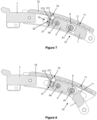
- THE figures 1 to 11 illustrate a first embodiment of a device 100 for adjusting the length of a bracelet.
- This adjustment device 100 is included within a folding clasp 200 provided with a cover 7, within which an adjustment assembly 10 is capable of sliding.
- This adjustment assembly 10 and the cover 7 of the folding clasp 200 together form the device 100 for adjusting the length of a bracelet.
- the folding clasp 200 comprises two folding blades 91, 92, as can be seen in particular on the Figure 1 .
- a first end longitudinal end of the first blade 91 is articulated on the cover 7 along a first axis A91, while a second longitudinal end of this first blade 91 is articulated to a first longitudinal end of the second blade 92 around a second axis A92.
- these blades 91, 92 are curved so as to best fit the shape of a wearer's wrist.
- the two blades 91, 92 are folded onto each other and retained in this configuration by a locking device 90 supported respectively by the cover 7 and by the second blade 92 at its second longitudinal end.
- the locking device 90 comprises in particular ball catches 93 housed within the second blade 92, which are designed to cooperate with notches 94 formed on the cover 7.
- the locking device 90 further comprises a safety cover 95 pivoted about an axis A95, which is designed to fold against the cover 7, once the blades 91 and 92 are folded onto each other and held in this position by the balls of the ball catches 93, which are held within the notches 94.
- the cover 7 is itself folded over the two blades 91, 92, and extends substantially superimposed on the first blade 91, so that the wearer can see the visible outer face of the cover 7, the two blades 91, 92 being hidden under the cover 7.
- the adjustment device 100 therefore comprises an adjustment assembly 10, more particularly represented by the Figure 4 , which comprises a first mesh 1 and a second mesh 2, connected together in an articulated manner around a first axis A1.
- the first mesh 1 comprises a tooth, which extends outwardly, acting as a first fixing element 11, which is intended to cooperate with a first succession of notches arranged on the outer wall 73 of the cover, more precisely in the inner surface 731 of the outer wall 73 of the cover, and acting as a second fixing element 71.
- This second fixing element fixing 71 therefore consists of a succession of notches arranged in a longitudinally aligned manner and in a centered manner in the interior surface 731 of the exterior wall 73 of the cover 7, as is more particularly shown in the Figure 11 .
- the notches are advantageously not open, so that the visible outer surface of the outer wall 73 of the cover 7 remains continuous and has an attractive aesthetic appearance.
- the first and second fixing elements together form a device for fixing the device for adjusting the length of the bracelet.
- the first link 1 of the adjustment assembly 10 also comprises a connecting pin 12 at its longitudinal end opposite the second link 2, which makes it possible to connect said first link 1 to other links or meshes of a bracelet strand, in particular of a metal bracelet, or to a strand of a flexible bracelet.
- the movement of the adjustment assembly 10 causes the movement of the bracelet strand and defines the length of the bracelet strand as a function of the position of the adjustment assembly 10.
- the second mesh 2 of the adjustment assembly 10 comprises, for its part, a ball ratchet, which projects from its outer surface, acting as a first indexing element 21.
- the ball 211 of the ball ratchet is intended to cooperate with a second succession of notches arranged on the outer wall 73 of the cover 7, acting as a second indexing element 72.
- the ball ratchet is here inserted with less play within a bore 22 formed on the outer surface of the second mesh 2.
- this ball ratchet could be fixed to the second mesh 2, in particular by driving, brazing or welding.
- the second indexing element 72 consists of a succession of notches arranged in a longitudinally aligned manner and in a centered manner in the inner surface 731 of the outer wall 73 of the cover 7, as is more particularly represented on the Figure 11 .
- these notches of the second indexing element 72 are aligned with the notches of the second fixing element 71 in the longitudinal direction.
- these notches of the second indexing element 72 are advantageously not open, so that the visible outer surface of the outer wall 73 of the cover 7 remains continuous and has an attractive aesthetic appearance.
- the first and second indexing elements together form an indexing device of the bracelet length adjustment device.
- the adjustment assembly 10 is mounted to move relative to the cover 7. Its movement is guided within the cover 7 by a guide device, which notably comprises guide pads 3 arranged laterally on the second mesh 2, provided to slide within slides or runners 74 arranged respectively on each of the side walls 75 of the cover 7, as can be seen in the figures 3 , 5 and 6 .
- First and second pads 3 are arranged at each of the ends of a first bar 4, arranged along the first transverse axis A1 to the two meshes 1, 2.
- This transverse axis A1 also defines an axis of articulation of the first and second meshes 1, 2.
- a return spring 6 is arranged around this axis, to return the first mesh 1 towards the cover 7, as will be detailed later.
- Third and fourth pads 3 are also arranged at each of the ends of a second bar 5, arranged along a second transverse axis A2 of the second mesh 2, parallel to the first transverse axis A1.
- These two bars 4, 5 pass through the second mesh 2 from one side to the other, so that the pads 3 arranged on their two respective ends protrude from the two side walls of the second mesh 2, in order to be able to be housed in the aforementioned slides 74 of the cover 7.
- the first bar 4 more particularly visible on the Figure 5 , comprises an annular central part 41 in which a spring 42 is arranged, which exerts an elastic thrust force on pivots 43 positioned at each of the ends of the bar 4.
- the pads 3 are arranged at the ends of each of the pivots 43.
- the spring 42 exerts an elastic thrust force on the pads 3, via the pivots 43, against the slides 74 of the cover.
- This thrust force is designed to guarantee the ideal positioning of the pads 3 in the slides to achieve reliable movement and with less play of the adjustment assembly 10.
- bar 5, visible on the Figure 6 comprises an annular central part 51 in which a spring 52 is arranged, which exerts an elastic thrust force on pivots 53 positioned at each of the ends of the bar 5.
- the pads 3 are arranged at the ends of each of the pivots 53.
- the spring 52 exerts an elastic thrust force on the pads 3, via the pivots 53, against the slides 74 of the cover.
- the bars 4, 5 and their pads 3 represent a first guide element of the guide device, and the slides 74 a second guide element of the guide device.
- the pads 3 may represent a first longitudinal stop element of the adjustment assembly 10 with respect to the cover 7, and the slides 74 a second longitudinal stop element of the adjustment assembly 10 with respect to the cover 7.
- the mesh 1 is further elastically biased against the outer wall 73 of the cover 7, in particular against the inner surface 731 of the outer wall 73 of the cover 7, as mentioned above, under the effect of a return spring 6 which is here in the form of a torsion spring.
- the first fastening element 11 i.e. the tooth of the first mesh 1 according to this embodiment, is elastically biased against a second fastening element 71, a notch of the cover according to this embodiment.
- the first fixing element could be fixed or locked in a stable position opposite a notch under the effect of a notching device which may involve, for example, one or more ball ratchets, without the latter necessarily inducing an elastic return force pressing the first fixing element 11 against or towards the second fixing element 71.
- a notching device which may involve, for example, one or more ball ratchets, without the latter necessarily inducing an elastic return force pressing the first fixing element 11 against or towards the second fixing element 71.
- THE figures 7 to 10 are sectional views passing through a vertical longitudinal median plane, which illustrate the operation of the adjustment device 100, in particular to allow maximum elongation of a bracelet equipped with such an adjustment device.
- FIG. 7 illustrates the adjustment assembly 10 in a first fixing position with respect to the cover 7.
- This first position is a stable position for fixing the bracelet in the clasp.
- the tooth forming the first fixing element 11 is pressed within a notch belonging to the second fixing element 71 under the effect of the return spring 6.
- the ball 211 belonging to the first indexing element 21 is located or is substantially located within a notch belonging to the second indexing element 72, under the effect of an elastic element belonging to the first indexing element 21, in particular a spring 212 of the ball ratchet.
- the fixing of the adjustment assembly 10 within the cover 7 is here essentially ensured by the fixing device, therefore by the cooperation of the two fixing elements, that is to say the tooth in a notch.
- this fixing device is designed to guarantee the stable fixing of the adjustment assembly 10 on the cover 7, during conventional wearing of the bracelet.
- FIG 8 illustrates an actuation of the adjustment assembly 10 in a first, temporary, intermediate position, in which the first link 1 is pivoted in a first direction of rotation around the first axis A1, against the return spring 6, so as to move the tooth away from the notch of the cover, thus releasing the first fixing element 11 from the second fixing element 71.
- the tooth thus retracted from the notch allows the adjustment assembly 10 to slide within the cover 7, in particular by means of the pads 3 provided to slide within the slides 74 formed on the side walls 75 of the cover.
- the ball 211 remains pressed against a notch in the cover under the effect of the spring 212.
- this indexing device is designed to allow temporary maintenance of the adjustment assembly relative to the cover, but also to allow adjustment by sliding of the adjustment assembly.
- the implementation of the adjustment continues by moving the adjustment assembly 10 to, for example, the position illustrated by the figure 9 , which corresponds to the maximum elongation of the bracelet.
- the adjustment assembly 10 can therefore be moved with respect to the cover 7 according to several temporary stable positions defined by the two indexing elements 21, 72, namely the ball ratchet and the succession of notches.
- the indexing device thus forms a pre-positioning means, which assists the user during a bracelet length adjustment, by allowing adequate temporary positioning of the adjustment assembly, before to act adequately on the fixing device.
- This indexing device is however not sufficient to fix the adjustment assembly, which can easily escape from the different indexed positions, by simple manual actuation by the user, to allow the length of the bracelet to continue to be adjusted.
- the indexing elements therefore do not fulfill a fixing function. They come in addition to the fixing device which is separate, as described previously.
- FIG 9 therefore illustrates the adjustment assembly 10 positioned in a temporary extreme position, opposite the cover 7 (located towards the right, on the figures 7 to 10 ). In this position, the ball 211 is in the last notch of the second indexing element 72.
- FIG. 10 illustrates the adjustment assembly 10 once the tooth 11 is positioned within the extreme notch of the second fixing element 71, following a rotation of the link 1 around the first axis A1 in a second direction of rotation opposite to the aforementioned first direction.
- the adjustment device is thus in a second fixing position, in which the length of the bracelet has been increased.
- the pads 3 arranged at the ends of each of the pivots 43 of the bar 4 are in particular in abutment against a longitudinal end of each of the slides 74.
- any other length adjustment is possible according to the same operation, the movement in the opposite direction (towards the left, on the figures 7 to 10 ) of the adjustment assembly allowing the bracelet to be shortened.
- the succession of notches forming the second fixing element 71 is arranged along a first longitudinal portion P1 of the outer wall 73 of the cover 7, while the succession of notches forming the second indexing element 72 is arranged along a second longitudinal portion P2 of the wall exterior 73 of the cover 7.
- the first and second aforementioned portions are distinct and arranged in continuity with each other in the longitudinal direction, as is more particularly visible on the Figure 11 .
- the second fixing element and the second indexing element are distinct.
- the first fixing element and the first indexing element are distinct.
- the fixing device there are as many notches of the fixing device as there are notches of the indexing device, for example five according to the illustrated embodiment.
- any other number of notches is possible, in particular two, three or four, or even more than five.
- the distance or pitch separating two successive notches of the fixing device and the indexing device respectively is advantageously the same or substantially the same.
- the architecture of the adjustment device is such that when the indexing elements are engaged, the fixing elements can cooperate to reach a fixing position of the adjustment device.
- THE figures 12 to 15 illustrate a second embodiment of a device 100' for adjusting the length of a bracelet.
- this second embodiment differs from the first embodiment in that the notches respectively forming the second fixing element 71a', 71b' and the second indexing element 72' are arranged differently, but always within the inner surface 731' of the outer wall 73' of the cover 7'.
- the second fixing element in fact comprises two parallel longitudinal successions of notches 71a', 71b', arranged laterally on the outer wall 73' of the cover 7'.
- the notches of the second indexing element 72' form a longitudinal succession of notches arranged in the central part of the outer wall 73' of the cover.
- these notches of the second indexing element 72' are at least partially interposed between the notches 71a', 71b' of the second fixing element 71'.
- Such an arrangement makes it possible to maximize the number of notches respectively of the second indexing element 72' and of the second fixing element 71' since they are capable of extending over the entire outer wall of the cover 7' in the longitudinal direction. More generally, such an arrangement therefore makes it possible to maximize the adjustment range of the length of a bracelet for a given longitudinal extent of the cover.
- FIG. 13 illustrates an adjustment assembly 10' adapted to such a cover 7' described above.
- This adjustment assembly 10' differs from that of the first embodiment in that its first mesh 1' comprises two teeth 11a', 11b' forming the first fixing element 11', aligned transversely, each designed to cooperate with one of the longitudinal successions of notches 71a', 71b' forming the second fixing element 71'.
- the first indexing element 21' of the second link 2' is here brought closer to the teeth 11a', 11b' of the first fixing element 11'.
- the distance d' separating them in the longitudinal direction is reduced relative to the distance d of the first embodiment, shown in the Figure 4 .
- This second embodiment thus allows to propose a 10' adjustment assembly more compact than the 10 adjustment assembly of the first embodiment.
- the figure 14 illustrates the adjustment device 100' in a length adjustment phase, in which the teeth 11a' (not visible), 11b' of the adjustment assembly 10' are retracted from a given pair of notches 71a' (not visible) and 71b' of the second fixing element.
- the distance separating two notches or two pairs of notches of the second fixing element is advantageously the same or substantially the same as that separating two notches of the second indexing element 72'.
- THE figures 15 to 18 illustrate a third embodiment of a device 100' for adjusting the length of a bracelet.
- This embodiment differs from the first two in that the second fixing element 71" and the second indexing element 72" are merged.
- a single longitudinal succession of notches in the inner surface 731" of the outer wall 73" of the cover 7" forms both the second fixing element 71" and the second indexing element 72".
- the same notch can thus simultaneously receive a first fixing element and a first indexing element.
- the first and second portions P1 and P2 overlap and are in particular merged.
- Such an arrangement makes it possible to further maximize the number of notches forming the second fixing element 71" and the second indexing element 72" for a given longitudinal cover extent.
- the adjustment assembly 10 comprises two articulated links 1", 2".
- the first link 1 comprises two teeth 11a" and 11b" aligned in the transverse direction, forming the first fixing element 11".
- the second link 2 comprises the first indexing element 21", which is here in the form of a wire spring 21", a first curved end 21a" of which at least partially coats or covers an axis 23", and a second free end 21b", arranged substantially between the two teeth 11a", 11b", is designed to cooperate with a notch forming the second indexing element 72" of the cover 7".
- the distance separating the end 21b" from the teeth 11a", 11b" in the longitudinal direction is zero or substantially zero in this embodiment, which further increases the compact nature of the adjustment assembly 10".
- the adjustment assembly 10" also has the specific feature of comprising a single pair of pads 3" arranged on either side of the second link 2" at a first axis A1", around which the first link 1" is articulated relative to the second link 2" (more particularly at a bar 4" arranged around the axis A1").
- a ball ratchet system (not visible in the figures), arranged at another axis A", parallel to the first axis A1", makes it possible to block the first link 1" relative to the second link 2", and therefore to block the two teeth 11a", 11b" opposite a notch of the second fixing element 71" of the outer wall 73" of the cover 7".
- the operating principle of the adjustment device 100" is similar to that of the adjustment devices 100, 100' of the two previous embodiments.
- a difference comes in particular from the fact that the first link 1" is not elastically returned against the outer wall 73" of the cover 7", but is locked in rotation relative to the second link 2" by means of the aforementioned ball ratchet system, in a position which makes it possible to guarantee the fixing of the adjustment element 100" on the cover 7".
- the Figure 17 represents the adjustment device 100" within which the adjustment assembly 10" is in a fixing position with respect to the cover 7", by the cooperation of the tooth portions 11a" (not visible) and 11b" with a first notch of the second fixing element 71".
- the free end 21b" of the wire spring 21" also cooperates with the same first notch, which is also a notch forming a second indexing element 72".
- This configuration corresponds here to a fixing position according to a minimal elongation of a bracelet provided with such an adjustment device 100".
- the second indexing element 71" and fixing element 72" comprise nine notches, which define as many positions of the adjustment assembly 10" with respect to the cover 7", and more generally lengths of a bracelet.
- the 21" spring could have a different shape.
- the figure 18 illustrates a 21" spring having a blade shape, the free end 21b" of which has a projection 211b" provided to improve cooperation with the succession of notches.
- the notches arranged on the outer wall 73" of the cover 7" extend continuously over a significant length in the transverse direction.
- Each notch thus comprises different zones which may belong to the second indexing element or to the second fixing element.
- the central zone of each notch is capable of cooperating with a first indexing element 21", and thus more precisely forms a second indexing element 72".
- the lateral zones of each notch form zones capable of cooperating with a first fixing element 11", and thus belong to the second fixing element.
- each notch may be separated into distinct zones, to thus separate the second indexing and fixing elements, according to a conformation approaching the second embodiment.
- the notches formed on the inner surface 731; 731'; 731" of the outer wall 73; 73'; 73" of the cover 7; 7'; 7" are non-through, so as not to be visible from the outside and to leave the visible outer surface of the cover intact.
- these notches could naturally be through, and could therefore be visible from the outside of the cover.
- the notches arranged in the outer wall of the cover may extend in the form of a row in the longitudinal direction, and may extend continuously or not in the transverse direction, a single notch may comprise different areas to fulfill the two functions of indexing and fixing, which thus appear to be merged on the cover.
- the notches could be completely separate for each of these two functions.
- the notches forming the second fixing element may or may not be centered on the outer wall of the cover.
- the profile of these notches may be symmetrical or asymmetrical, in order to generate a different release depending on the direction of actuation of the adjustment assembly.
- the first indexing element may be in the form of a ball ratchet. More generally, this ball may be replaced by any element with a hemispherical shape, in particular by a cylinder or a stud with one end having a hemispherical shape. Alternatively, this ball may be replaced by a cylinder or a stud, one end of which is provided with a tooth, this tooth being able to have a symmetrical or asymmetrical profile. Thus, more generally, the first indexing element may be in the form of an elastic ratchet. Such an elastic ratchet may or may not be removable.
- the figure 19 illustrates a variant of the first indexing element taking the form of a non-removable elastic pawl 21* comprising a stud 211* one end of which has a hemispherical shape, which is elastically returned by a spring 212*.
- the first indexing element may be in the form of a spring, such as a wire spring or a leaf spring, as represented by the third embodiment.
- the free end 21b" of the spring 21" may have a symmetrical or asymmetrical profile.
- the first indexing element comprises one or more elastic elements, capable of cooperating elastically with a notch on the cover.
- the first fastener could be in a form other than those illustrated. It can include any form of teeth, symmetrical or not, and any other number of teeth.
- the indexing elements and/or the fastening elements may be reversed.
- the first fastening element could be on the second link, which would be retractable, and the first indexing element could be on the first link of the adjustment assembly.
- the notches could be arranged on the adjustment assembly and not on the cover, the latter then comprising a projecting elastic element for the indexing function, and one or more teeth projecting towards the adjustment assembly for the fastening function.
- the adjustment assembly is preferably guided within the clasp cover by a guide device, in particular by means of guide pads provided to slide within slides or runners arranged respectively on each of the side walls of the cover.
- the guide device could be in a completely different form.
- it could more simply comprise a projection formed in particular on an outer surface of the second mesh of the adjustment assembly, which is provided to slide within a groove formed on the outer wall of the cover.
- the first guide element comprises a projecting element, such as a pad, and an elastic element, for example arranged within a bar, to act on the projecting element in the direction of the cover, in order to maintain said element in cooperation with the second guide element of the cover, in particular a groove or a runner as shown in the various embodiments.
- the first indexing element may be distinct and/or independent of the first guide element.
- the first indexing element may comprise an elastic element, as described above, distinct from an elastic means used in the first guide element.
- the elastic element of the first indexing element is distinct from the guide device.
- the first indexing element may alternatively or additionally be distinct and/or independent of the second guide element arranged on the cover. More specifically, the ball or the elastic element or any other projecting element belonging to the first indexing element may cooperate with an area of the cover distinct from the second guide element, for example outside a groove or a slide provided for guiding the adjustment assembly.
- the second indexing element, arranged on the cover may be distinct and/or independent of the second guide element.
- the second indexing element may be arranged on a wall of the cover separate from the wall on which the second guide element is arranged.
- the second indexing element may also be independent and/or separate from the first guide element, i.e. this first guide element does not cooperate with the second indexing element for implementing the guide function.
- the indexing device is at least partially independent and/or distinct from the fixing device.
- the adjustment device is included within a folding clasp equipped with a locking device.
- the clasp could have a completely different form.
- the locking device could be without a safety cover.
- the adjustment device of the invention the adjustment of the length of a bracelet becomes assisted and very user-friendly. If the user wishes to continue the adjustment, he continues to move the adjustment assembly, and his effort allows the release of the intermediate indexing elements encountered, against the effort of the elastic element of the indexing device, in particular of the first indexing element.
- the invention also relates to a bracelet and/or a clasp and/or a wristwatch, which incorporate(s) a bracelet extension device as described previously.
Landscapes
- Adornments (AREA)
- Buckles (AREA)
Priority Applications (4)
| Application Number | Priority Date | Filing Date | Title |
|---|---|---|---|
| EP22156512.0A EP4226806B1 (fr) | 2022-02-14 | 2022-02-14 | Dispositif de réglage de la longueur d'un bracelet |
| US18/168,070 US12274336B2 (en) | 2022-02-14 | 2023-02-13 | Device for adjusting the length of a bracelet |
| CN202310111385.8A CN116584745A (zh) | 2022-02-14 | 2023-02-14 | 用于调节表链的长度的装置 |
| JP2023020447A JP2023118123A (ja) | 2022-02-14 | 2023-02-14 | ブレスレットの長さを調節するための装置 |
Applications Claiming Priority (1)
| Application Number | Priority Date | Filing Date | Title |
|---|---|---|---|
| EP22156512.0A EP4226806B1 (fr) | 2022-02-14 | 2022-02-14 | Dispositif de réglage de la longueur d'un bracelet |
Publications (2)
| Publication Number | Publication Date |
|---|---|
| EP4226806A1 EP4226806A1 (fr) | 2023-08-16 |
| EP4226806B1 true EP4226806B1 (fr) | 2025-03-19 |
Family
ID=80683164
Family Applications (1)
| Application Number | Title | Priority Date | Filing Date |
|---|---|---|---|
| EP22156512.0A Active EP4226806B1 (fr) | 2022-02-14 | 2022-02-14 | Dispositif de réglage de la longueur d'un bracelet |
Country Status (4)
| Country | Link |
|---|---|
| US (1) | US12274336B2 (https=) |
| EP (1) | EP4226806B1 (https=) |
| JP (1) | JP2023118123A (https=) |
| CN (1) | CN116584745A (https=) |
Families Citing this family (2)
| Publication number | Priority date | Publication date | Assignee | Title |
|---|---|---|---|---|
| EP4124256B1 (fr) * | 2021-07-30 | 2024-04-24 | Rolex Sa | Dispositif de réglage de la longueur d'un bracelet |
| JP1784531S (ja) * | 2023-03-10 | 2024-11-13 | 腕時計用ベルトの留め金 |
Family Cites Families (4)
| Publication number | Priority date | Publication date | Assignee | Title |
|---|---|---|---|---|
| CH690116A5 (fr) | 1996-07-17 | 2000-05-15 | Rolex Montres | Dispositif de réglage de la longueur d'un bracelet muni d'un fermoir à lames déployantes. |
| DE602006007360D1 (de) | 2006-10-06 | 2009-07-30 | Rolex Sa | Armbandverschluss |
| EP3527101B1 (fr) | 2018-02-16 | 2024-03-06 | Rolex Sa | Dispositif horloger de type habillage à composants mobiles |
| WO2019166671A1 (fr) * | 2018-03-02 | 2019-09-06 | Dexel S.A. | Fermoir pour bracelet comportant un dispositif de réglage de longueur du bracelet |
-
2022
- 2022-02-14 EP EP22156512.0A patent/EP4226806B1/fr active Active
-
2023
- 2023-02-13 US US18/168,070 patent/US12274336B2/en active Active
- 2023-02-14 JP JP2023020447A patent/JP2023118123A/ja active Pending
- 2023-02-14 CN CN202310111385.8A patent/CN116584745A/zh active Pending
Also Published As
| Publication number | Publication date |
|---|---|
| EP4226806A1 (fr) | 2023-08-16 |
| US20230255327A1 (en) | 2023-08-17 |
| CN116584745A (zh) | 2023-08-15 |
| JP2023118123A (ja) | 2023-08-24 |
| US12274336B2 (en) | 2025-04-15 |
Similar Documents
| Publication | Publication Date | Title |
|---|---|---|
| EP3329797B1 (fr) | Dispositif de réglage de la longueur d'un bracelet | |
| EP2606762B1 (fr) | Fermoir à différents réglages de longueur de bracelet | |
| EP2725937B1 (fr) | Fermoir extensible pour bracelet notamment d'une montre | |
| EP3893688B1 (fr) | Dispositif de réglage fin de la longueur d'un bracelet et bracelet comportant un tel dispositif au moins | |
| EP4226806B1 (fr) | Dispositif de réglage de la longueur d'un bracelet | |
| CH704335B1 (fr) | Fermoir extensible pour bracelet notamment d'une montre. | |
| EP1943917B1 (fr) | Fermoir à boucle déployante pour bracelet | |
| EP4124256B1 (fr) | Dispositif de réglage de la longueur d'un bracelet | |
| EP3928652B1 (fr) | Dispositif de verrouillage pour fermoir de bracelet | |
| EP3329796B1 (fr) | Dispositif de reglage de confort de la longueur d'un bracelet | |
| EP0115364B1 (fr) | Fermoir de bracelet à boucle déployante | |
| EP3941300B1 (fr) | Fermoir pour bracelet | |
| EP0319461B1 (fr) | Fermoir de bracelet | |
| EP0927526B1 (fr) | Fermoir de bracelet | |
| EP3569090B1 (fr) | Systeme d`attache d'un bracelet a une boite de montre | |
| EP3599930B1 (fr) | Fermoir a boucle deployante | |
| EP3219220B1 (fr) | Bracelet comprenant un dispositif de réglage de la longueur | |
| EP0683993B1 (fr) | Dispositif de fixation d'un bracelet à une montre | |
| EP3777599B1 (fr) | Articulation elastique pour assemblage horloger | |
| EP3886641B1 (fr) | Montre comprenant deux brins de bracelet | |
| CH719481B1 (fr) | Fermoir à boucle déployante | |
| EP4489613A1 (fr) | Fermoir a boucle deployante | |
| CH712215B1 (fr) | Dispositif de réglage pour bracelet. | |
| FR2694684A1 (fr) | Dispositif de fermeture pour bracelets. |
Legal Events
| Date | Code | Title | Description |
|---|---|---|---|
| PUAI | Public reference made under article 153(3) epc to a published international application that has entered the european phase |
Free format text: ORIGINAL CODE: 0009012 |
|
| STAA | Information on the status of an ep patent application or granted ep patent |
Free format text: STATUS: THE APPLICATION HAS BEEN PUBLISHED |
|
| AK | Designated contracting states |
Kind code of ref document: A1 Designated state(s): AL AT BE BG CH CY CZ DE DK EE ES FI FR GB GR HR HU IE IS IT LI LT LU LV MC MK MT NL NO PL PT RO RS SE SI SK SM TR |
|
| P01 | Opt-out of the competence of the unified patent court (upc) registered |
Effective date: 20231004 |
|
| STAA | Information on the status of an ep patent application or granted ep patent |
Free format text: STATUS: REQUEST FOR EXAMINATION WAS MADE |
|
| 17P | Request for examination filed |
Effective date: 20240212 |
|
| RBV | Designated contracting states (corrected) |
Designated state(s): AL AT BE BG CH CY CZ DE DK EE ES FI FR GB GR HR HU IE IS IT LI LT LU LV MC MK MT NL NO PL PT RO RS SE SI SK SM TR |
|
| RIC1 | Information provided on ipc code assigned before grant |
Ipc: A44C 5/24 20060101AFI20240529BHEP |
|
| GRAP | Despatch of communication of intention to grant a patent |
Free format text: ORIGINAL CODE: EPIDOSNIGR1 |
|
| STAA | Information on the status of an ep patent application or granted ep patent |
Free format text: STATUS: GRANT OF PATENT IS INTENDED |
|
| INTG | Intention to grant announced |
Effective date: 20241008 |
|
| GRAS | Grant fee paid |
Free format text: ORIGINAL CODE: EPIDOSNIGR3 |
|
| GRAA | (expected) grant |
Free format text: ORIGINAL CODE: 0009210 |
|
| STAA | Information on the status of an ep patent application or granted ep patent |
Free format text: STATUS: THE PATENT HAS BEEN GRANTED |
|
| AK | Designated contracting states |
Kind code of ref document: B1 Designated state(s): AL AT BE BG CH CY CZ DE DK EE ES FI FR GB GR HR HU IE IS IT LI LT LU LV MC MK MT NL NO PL PT RO RS SE SI SK SM TR |
|
| REG | Reference to a national code |
Ref country code: GB Ref legal event code: FG4D Free format text: NOT ENGLISH |
|
| REG | Reference to a national code |
Ref country code: CH Ref legal event code: EP |
|
| REG | Reference to a national code |
Ref country code: IE Ref legal event code: FG4D Free format text: LANGUAGE OF EP DOCUMENT: FRENCH |
|
| REG | Reference to a national code |
Ref country code: DE Ref legal event code: R096 Ref document number: 602022011829 Country of ref document: DE |
|
| PG25 | Lapsed in a contracting state [announced via postgrant information from national office to epo] |
Ref country code: RS Free format text: LAPSE BECAUSE OF FAILURE TO SUBMIT A TRANSLATION OF THE DESCRIPTION OR TO PAY THE FEE WITHIN THE PRESCRIBED TIME-LIMIT Effective date: 20250619 |
|
| PG25 | Lapsed in a contracting state [announced via postgrant information from national office to epo] |
Ref country code: FI Free format text: LAPSE BECAUSE OF FAILURE TO SUBMIT A TRANSLATION OF THE DESCRIPTION OR TO PAY THE FEE WITHIN THE PRESCRIBED TIME-LIMIT Effective date: 20250319 |
|
| REG | Reference to a national code |
Ref country code: LT Ref legal event code: MG9D |
|
| PG25 | Lapsed in a contracting state [announced via postgrant information from national office to epo] |
Ref country code: NO Free format text: LAPSE BECAUSE OF FAILURE TO SUBMIT A TRANSLATION OF THE DESCRIPTION OR TO PAY THE FEE WITHIN THE PRESCRIBED TIME-LIMIT Effective date: 20250619 |
|
| PG25 | Lapsed in a contracting state [announced via postgrant information from national office to epo] |
Ref country code: HR Free format text: LAPSE BECAUSE OF FAILURE TO SUBMIT A TRANSLATION OF THE DESCRIPTION OR TO PAY THE FEE WITHIN THE PRESCRIBED TIME-LIMIT Effective date: 20250319 |
|
| PG25 | Lapsed in a contracting state [announced via postgrant information from national office to epo] |
Ref country code: LV Free format text: LAPSE BECAUSE OF FAILURE TO SUBMIT A TRANSLATION OF THE DESCRIPTION OR TO PAY THE FEE WITHIN THE PRESCRIBED TIME-LIMIT Effective date: 20250319 |
|
| PG25 | Lapsed in a contracting state [announced via postgrant information from national office to epo] |
Ref country code: GR Free format text: LAPSE BECAUSE OF FAILURE TO SUBMIT A TRANSLATION OF THE DESCRIPTION OR TO PAY THE FEE WITHIN THE PRESCRIBED TIME-LIMIT Effective date: 20250620 Ref country code: BG Free format text: LAPSE BECAUSE OF FAILURE TO SUBMIT A TRANSLATION OF THE DESCRIPTION OR TO PAY THE FEE WITHIN THE PRESCRIBED TIME-LIMIT Effective date: 20250319 |
|
| REG | Reference to a national code |
Ref country code: NL Ref legal event code: MP Effective date: 20250319 |
|
| REG | Reference to a national code |
Ref country code: AT Ref legal event code: MK05 Ref document number: 1776183 Country of ref document: AT Kind code of ref document: T Effective date: 20250319 |
|
| PG25 | Lapsed in a contracting state [announced via postgrant information from national office to epo] |
Ref country code: NL Free format text: LAPSE BECAUSE OF FAILURE TO SUBMIT A TRANSLATION OF THE DESCRIPTION OR TO PAY THE FEE WITHIN THE PRESCRIBED TIME-LIMIT Effective date: 20250319 |
|
| PG25 | Lapsed in a contracting state [announced via postgrant information from national office to epo] |
Ref country code: SE Free format text: LAPSE BECAUSE OF FAILURE TO SUBMIT A TRANSLATION OF THE DESCRIPTION OR TO PAY THE FEE WITHIN THE PRESCRIBED TIME-LIMIT Effective date: 20250319 |
|
| PG25 | Lapsed in a contracting state [announced via postgrant information from national office to epo] |
Ref country code: SM Free format text: LAPSE BECAUSE OF FAILURE TO SUBMIT A TRANSLATION OF THE DESCRIPTION OR TO PAY THE FEE WITHIN THE PRESCRIBED TIME-LIMIT Effective date: 20250319 |
|
| PG25 | Lapsed in a contracting state [announced via postgrant information from national office to epo] |
Ref country code: ES Free format text: LAPSE BECAUSE OF FAILURE TO SUBMIT A TRANSLATION OF THE DESCRIPTION OR TO PAY THE FEE WITHIN THE PRESCRIBED TIME-LIMIT Effective date: 20250319 Ref country code: PT Free format text: LAPSE BECAUSE OF FAILURE TO SUBMIT A TRANSLATION OF THE DESCRIPTION OR TO PAY THE FEE WITHIN THE PRESCRIBED TIME-LIMIT Effective date: 20250721 |
|
| PG25 | Lapsed in a contracting state [announced via postgrant information from national office to epo] |
Ref country code: PL Free format text: LAPSE BECAUSE OF FAILURE TO SUBMIT A TRANSLATION OF THE DESCRIPTION OR TO PAY THE FEE WITHIN THE PRESCRIBED TIME-LIMIT Effective date: 20250319 Ref country code: IT Free format text: LAPSE BECAUSE OF FAILURE TO SUBMIT A TRANSLATION OF THE DESCRIPTION OR TO PAY THE FEE WITHIN THE PRESCRIBED TIME-LIMIT Effective date: 20250319 |
|
| PG25 | Lapsed in a contracting state [announced via postgrant information from national office to epo] |
Ref country code: AT Free format text: LAPSE BECAUSE OF FAILURE TO SUBMIT A TRANSLATION OF THE DESCRIPTION OR TO PAY THE FEE WITHIN THE PRESCRIBED TIME-LIMIT Effective date: 20250319 |
|
| PG25 | Lapsed in a contracting state [announced via postgrant information from national office to epo] |
Ref country code: EE Free format text: LAPSE BECAUSE OF FAILURE TO SUBMIT A TRANSLATION OF THE DESCRIPTION OR TO PAY THE FEE WITHIN THE PRESCRIBED TIME-LIMIT Effective date: 20250319 Ref country code: CZ Free format text: LAPSE BECAUSE OF FAILURE TO SUBMIT A TRANSLATION OF THE DESCRIPTION OR TO PAY THE FEE WITHIN THE PRESCRIBED TIME-LIMIT Effective date: 20250319 |
|
| PG25 | Lapsed in a contracting state [announced via postgrant information from national office to epo] |
Ref country code: RO Free format text: LAPSE BECAUSE OF FAILURE TO SUBMIT A TRANSLATION OF THE DESCRIPTION OR TO PAY THE FEE WITHIN THE PRESCRIBED TIME-LIMIT Effective date: 20250319 |
|
| PG25 | Lapsed in a contracting state [announced via postgrant information from national office to epo] |
Ref country code: SK Free format text: LAPSE BECAUSE OF FAILURE TO SUBMIT A TRANSLATION OF THE DESCRIPTION OR TO PAY THE FEE WITHIN THE PRESCRIBED TIME-LIMIT Effective date: 20250319 |
|
| PG25 | Lapsed in a contracting state [announced via postgrant information from national office to epo] |
Ref country code: IS Free format text: LAPSE BECAUSE OF FAILURE TO SUBMIT A TRANSLATION OF THE DESCRIPTION OR TO PAY THE FEE WITHIN THE PRESCRIBED TIME-LIMIT Effective date: 20250719 |
|
| REG | Reference to a national code |
Ref country code: DE Ref legal event code: R097 Ref document number: 602022011829 Country of ref document: DE |
|
| PG25 | Lapsed in a contracting state [announced via postgrant information from national office to epo] |
Ref country code: DK Free format text: LAPSE BECAUSE OF FAILURE TO SUBMIT A TRANSLATION OF THE DESCRIPTION OR TO PAY THE FEE WITHIN THE PRESCRIBED TIME-LIMIT Effective date: 20250319 |
|
| PLBE | No opposition filed within time limit |
Free format text: ORIGINAL CODE: 0009261 |
|
| STAA | Information on the status of an ep patent application or granted ep patent |
Free format text: STATUS: NO OPPOSITION FILED WITHIN TIME LIMIT |
|
| REG | Reference to a national code |
Ref country code: CH Ref legal event code: L10 Free format text: ST27 STATUS EVENT CODE: U-0-0-L10-L00 (AS PROVIDED BY THE NATIONAL OFFICE) Effective date: 20260128 |
|
| 26N | No opposition filed |
Effective date: 20251222 |
|
| REG | Reference to a national code |
Ref country code: CH Ref legal event code: U11 Free format text: ST27 STATUS EVENT CODE: U-0-0-U10-U11 (AS PROVIDED BY THE NATIONAL OFFICE) Effective date: 20260301 |
|
| PGFP | Annual fee paid to national office [announced via postgrant information from national office to epo] |
Ref country code: GB Payment date: 20260219 Year of fee payment: 5 |
|
| PGFP | Annual fee paid to national office [announced via postgrant information from national office to epo] |
Ref country code: DE Payment date: 20260206 Year of fee payment: 5 |
|
| PGFP | Annual fee paid to national office [announced via postgrant information from national office to epo] |
Ref country code: FR Payment date: 20260227 Year of fee payment: 5 |
|
| PGFP | Annual fee paid to national office [announced via postgrant information from national office to epo] |
Ref country code: CH Payment date: 20260301 Year of fee payment: 5 |