EP4226087B1 - Kochfeld mit rost mit flachem rahmen - Google Patents
Kochfeld mit rost mit flachem rahmen Download PDFInfo
- Publication number
- EP4226087B1 EP4226087B1 EP20956864.1A EP20956864A EP4226087B1 EP 4226087 B1 EP4226087 B1 EP 4226087B1 EP 20956864 A EP20956864 A EP 20956864A EP 4226087 B1 EP4226087 B1 EP 4226087B1
- Authority
- EP
- European Patent Office
- Prior art keywords
- frame
- heat shield
- burner body
- gas hob
- hob according
- Prior art date
- Legal status (The legal status is an assumption and is not a legal conclusion. Google has not performed a legal analysis and makes no representation as to the accuracy of the status listed.)
- Active
Links
Images
Classifications
-
- F—MECHANICAL ENGINEERING; LIGHTING; HEATING; WEAPONS; BLASTING
- F24—HEATING; RANGES; VENTILATING
- F24C—DOMESTIC STOVES OR RANGES ; DETAILS OF DOMESTIC STOVES OR RANGES, OF GENERAL APPLICATION
- F24C15/00—Details
- F24C15/10—Tops, e.g. hot plates; Rings
- F24C15/107—Pan supports or grates therefor
-
- F—MECHANICAL ENGINEERING; LIGHTING; HEATING; WEAPONS; BLASTING
- F24—HEATING; RANGES; VENTILATING
- F24C—DOMESTIC STOVES OR RANGES ; DETAILS OF DOMESTIC STOVES OR RANGES, OF GENERAL APPLICATION
- F24C15/00—Details
- F24C15/10—Tops, e.g. hot plates; Rings
- F24C15/101—Tops, e.g. hot plates; Rings provisions for circulation of air
-
- F—MECHANICAL ENGINEERING; LIGHTING; HEATING; WEAPONS; BLASTING
- F24—HEATING; RANGES; VENTILATING
- F24C—DOMESTIC STOVES OR RANGES ; DETAILS OF DOMESTIC STOVES OR RANGES, OF GENERAL APPLICATION
- F24C3/00—Stoves or ranges for gaseous fuels
- F24C3/08—Arrangement or mounting of burners
- F24C3/085—Arrangement or mounting of burners on ranges
-
- Y—GENERAL TAGGING OF NEW TECHNOLOGICAL DEVELOPMENTS; GENERAL TAGGING OF CROSS-SECTIONAL TECHNOLOGIES SPANNING OVER SEVERAL SECTIONS OF THE IPC; TECHNICAL SUBJECTS COVERED BY FORMER USPC CROSS-REFERENCE ART COLLECTIONS [XRACs] AND DIGESTS
- Y02—TECHNOLOGIES OR APPLICATIONS FOR MITIGATION OR ADAPTATION AGAINST CLIMATE CHANGE
- Y02B—CLIMATE CHANGE MITIGATION TECHNOLOGIES RELATED TO BUILDINGS, e.g. HOUSING, HOUSE APPLIANCES OR RELATED END-USER APPLICATIONS
- Y02B40/00—Technologies aiming at improving the efficiency of home appliances, e.g. induction cooking or efficient technologies for refrigerators, freezers or dish washers
Definitions
- the invention relates to a hob comprising a single hob grid disposed on the hob to support the pan at a safe cooking distance to a burner.
- a pan is disposed on a burner provided on the top plate at a height defining a flame distance.
- a grate is provided on a hotplate and the pan rest on the grate, aligned on the respective burner.
- the hob has support legs rising from the hob to the burner.
- the support leg of the grate is in the form of a frame surrounding the entire hob and grate bars extending from the frame to each burner.
- the frame of the single hob grill around the burner is provided to surround the periphery with a circular frame. It has an inverted L-like form rising from the frame ring with the support legs facing each other.
- Each support leg extends upwards at equal height and bends towards each other, forming a supporting portion in a plane extending from its free ends parallel to the top plate.
- EP2564121 discloses a gas hob with a heat shield and a hob with at least one gas burner on a tempered glass or glass ceramic cooktop.
- the heat shield is rectangular in shape and the hob includes a frame that attaches shape to the heat shield in the polygonal flat disc structure to protect the hob thermally. Further relevant prior art is given in KR20120033236 A and US7291009 B2 .
- the object of the invention is to increase the burner operating performance in hob with a single grate and a heat shield around the burner.
- a hob is comprising a bowl-shaped burner body disposed in an opening on a top plate and a flame spreader is extending radially outwardly on the burner body so as to provide an air intake corridor with the top plate; a grate having a frame that surrounds the burner body at a distance and at least one carrier arm rising from the frame and extending towards the flame spreader; a flat heat shield arranged as a spacer between the burner body and the frame.
- the frame is in the form of a flat plate and thickness of the frame is surrounding the heat shield from its periphery is arranged to equal or smaller than the height of the heat shield.
- the frame in the form of a flat thin plate does not create any obstacles in front of the air intake corridor.
- the burner body is an injector holder in the form of a cup and connected to the injector burner body with gas line connection.
- Layout can be arranged vertically or horizontally.
- a mounting section at the bottom of the carrier arm is extending from the top of the frame to the outer edge in an L-like form. In this way, the mounting section contact surface between the frame and the carrier arm is increased by ensuring that the mounting section wraps around the frame both from the top and from the outside. In an alternative embodiment, it is also possible for the mounting section of the carrier arm to extend to the inner edge of the frame.
- a preferred embodiment of the invention includes a base following the mounting section gradually rests at least partially on the top plate.
- the base allows the support arm to be supported both by the frame and directly by the top plate.
- the carrier arm is in the form of a solid thin and flat plate rising perpendicular to the frame.
- the flat and vertical plate carrier arm provides the least intersection possibility with the flame crown formed by the flame spreader.
- the thickness of the carrier arm is substantially equal to the thickness of the frame. In this way, it is possible to obtain support arms, for example, from the same sheet metal from which the frame is produced.
- a flat upper wall of the frame of the grate is aligned with the upper wall of the heat shield to extend in the same horizontal plane.
- intake air pass over the frame extending from the bottom of the air intake corridor without disturbed by any surface deformation that will reduce the pressure of the radially inwardly moving ambient air.
- the flame spreader comprises a rim extending parallel to the radial inward air intake corridor to confine from the top, through which primary air pass through between the flame spreader and heat shield.
- the rim part extends inward on the flame spreader and provides a corridor with air passage on the heat shield. The ambient air cools and reduces thermal deformations the heat shield by passing over.
- a mounting part of the heat shield is aligned into a mounting hole provided on a flange of the burner body extending to the opening such that a fixing element is able to be inserted. In this way, when the burner body is inserted into the opening, it is possible to mount the heat shield on the top plate over the flange.
- the heat shield is having a stepped outer edge fitted from a lower wall to the frame in a covering manner. Since the frame rest on the heat shield, it is ensured that the frame hides the mounting section of the heat shield and the top plate.
- an elevated portion equal to the thickness of the frame is provided between the outer edge and the planar upper wall. In this way, when the frame is disposed on the outer edge from the lower wall, it is disposed on the same plane with the upper edge from the adjacent edge with the elevation part.
- the heat shield is formed from a metal plate.
- the metal plate acts as a wing and ensures that the heat emitted from the burner body is transferred to the ambient by convection. Since the top plate is not directly adjacent to the burner body, it is removed from the high temperature region formed in the neighbouring part.
- the cooktop includes ceramic or toughened glass. In this way, when the burner body is disposed in its opening, protected from the negative effects of temperatures with its heat shield.
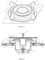
- a flame spreader (30) on a burner body (50) disposed in a circular opening on a hard glass cooktop (1) and a hob grate (10) with four carrier arms (20) around it is shown in perspective.
- the flame spreader (30) is in a cylindrical form and there is a flat metal cover (33) on top part.
- a heat shield (40) extending radially outwards from the opening (2) rest on the top plate (1).
- the heat shield (40) is formed by pressing a flat metal plate and is one piece in annular structure.
- a hob grate (10) with a rectangular flat frame (12) is removably seated on the junction between the heat shield (40) and the hob (1).
- the heat shield (40) is in a circular gradual form and an elevated portion (44) provided by the outer stage part and an inner edge (11) of the frame (12) are adjacent to each other.
- Four carrier arms (20) perpendicular to the frame (12) facing each other are mounted on the frame (12) from a corresponding mounting section (25) in the lower part of the frame (12) in a way that makes an angle of 90 degrees.
- the support arm (20) has an L-like form with its long arm extending above it at a distance from the cover (33).
- the short arm forms a lifting arm (23) and raises a long support extension (23) parallel to the cooktop (1) at a distance, higher than the height of the cover (33).
- the lower part of the lifting arm (23) has a flat base (22) that fits directly onto the hob (1).
- the base (22) is adjacent to the mounting section.
- a through hole (21) is provided at the top of the base (22) .
- a silicone or rubber foot (not shown) can be passed through the hole (21) to support the base (22).
- the upper wall (15) of the frame (12) and the upper wall (41) of the heat shield (40) adjacent to it are provided in a same plane parallel to and above the top plate (1).
- the opening (2) is formed by making a circular hole on the cooktop (1), which is a toughened glass plate structure.
- the aluminum burner body (50) in the form of a cup is disposed in the opening (2) with its opening is facing upwards.
- An injector (60) provided in the base is disposed vertically in an inner chamber (56) surrounded by the burner body (50).
- the injector (60) is connected to a gas inlet (62) at its lower end facing outward.
- a flange (51) extends radially outward on the upper part of the burner body (50). Opposite mounting holes (52) are drilled on the flange (51).
- the heat shield (40) is formed from metal sheet and surrounds the mouth (53) of the burner body (50) from an inner edge (46). A mounting portion (43) adjacent to the inner edge (46) is collapsed into the mounting hole (52) aligned.
- a connection element for example, secure the heat shield (40) from the inner edge (46) to the burner body (50) by passing through the mounting hole (52) in such a way that its head fits into the screw mounting part (43).
- the heat shield (40) extends radially outwards with an upper wall (41) that is flat and parallel to the top plate (1) and covers the opening (2) between its inner edge (46) and an opposite outer edge (42).
- the outer edge (42) is in a stepped structure and bends vertically downwards as much as the thickness of the frame (12) and forms an elevated portion (44).
- the lower wall (16) which forms the flat base of the frame (12), sits on the outer edge (42) close to the inner edge (11).
- the upper wall (15) of the frame (12) and the upper wall (41) of the heat shield (40) are aligned in the same plane.
- the lower wall (16) of the frame (12) sits on the cooktop (1) near the outer edge (14).
- the outer edge 42 and the lower wall 16 are in the same plane.
- the mushroom-shaped flame spreader (30) sits on the open mouth (53) of the burner body (50) in a removable way.
- a flat rim (32) forming the lower part of the cylindrical flame spreader (30) extends radially outwards and an air intake corridor (a) at a distance between them and the upper wall (41) limits the entrance.
- the rim part (32) reaches an inward channel (34) from which it is directed to a venturi element in the center.
- the holes (36) separated by the tooth-shaped walls are covered by the metal cover (33).
- the support extension (24) at the upper end of the lifting arm (23) extends towards the cover (33) in a way that leaves a distance from the flame spreader.
- the rim (32) together with the channel (34) following it form the air intake corridor (a), which provides radial inward air movement between the heat shield (40) upper wall (41) and the lower part of the flame spreader (30).
- the air intake corridor (a) reaches the inner chamber (56) from one end and provides mixing of the flammable gas coming from the injector (60) with the ambient air.
- the gas-air mixture is taken out of the holes (36) and feeds the flame spreader formed by ignition.
- the height of the outer edge (14) and the inner edge (11) of the frame (12) on the hob grill (10) is adjusted equally.
- the lower wall (16) and the upper wall (15) are adjusted equally to provide a rectangular section.
- the height of the outer edge (14) and the inner edge (11) is less than the width of the lower wall (16) and the upper wall (15). Since the inner edge (11) and the elevation part (44) have equal heights, when the single hob grill (10) is disposed on the hob (1) by wrapping around the burner body (50), it does not create any obstacle in front of the planar floor of the air intake corridor (a).
- the carrier arms (20) fixed vertically on the frame (12) are manufactured by cutting from the same sheet metal as the frame (12). Therefore, the thickness of the carrier arms (20) and the height of the frame (12) are equal.
- the frame (12) and carrier arms (20) cut from a thin and flat metal sheet provide a light hob (10).
- the thin carrier arms (20) affect the air drawn from the ambient in the least way and have high combustion efficiency. is happening.
- the base (22) of the lifting arms (20) of the support arms (20) extends radially outward with respect to the center of the frame (12), providing an expanded support area together with the flat frame (12), and the support extension (24) is disposed on the glass cooktop when the pot sits on it unevenly. (1) by reducing the pressure, any damage is prevented.
Landscapes
- Engineering & Computer Science (AREA)
- Chemical & Material Sciences (AREA)
- Combustion & Propulsion (AREA)
- Mechanical Engineering (AREA)
- General Engineering & Computer Science (AREA)
- Baking, Grill, Roasting (AREA)
Claims (10)
- Ein Gas-Kochfeld, umfassend einen becherförmigen Brennerkörper (50), der in einer Öffnung (2) auf einer oberen Platte (1) angeordnet ist, und einen Flammenverteiler (30), der sich radial nach außen auf dem Brennerkörper (50) erstreckt, um mit der oberen Platte (1) einen Lufteinlasskorridor (a) zu bilden; einen Rost (10) mit einem Rahmen (12), der den Brennerkörper (50) in einem Abstand umgibt, und mindestens einem Trägerarm (20), der vom Rahmen (12) aufsteigt und sich in Richtung des Flammenverteilers (30) erstreckt; einen flachen Hitzeschild (40), der als Abstandshalter zwischen dem Brennerkörper (50) und dem Rahmen (12) angeordnet ist, dadurch gekennzeichnet, dass der Rahmen (12) in Form einer flachen Platte vorliegt und die Dicke des Rahmens (12), der den Hitzeschild (40) an dessen Peripherie umgibt, gleich oder kleiner als die Höhe des Hitzeschilds (40) ist, wobei eine flache obere Wand (15) des Rahmens (12) des Rosts (10) mit der oberen Wand (41) des Hitzeschilds (40) ausgerichtet ist, um in derselben horizontalen Ebene zu verlaufen, und ein flacher Rand (32), der den unteren Teil des zylindrischen Flammenverteilers (30) bildet, sich radial nach außen erstreckt, um den Eintritt eines Lufteinlasskorridors (a) mit der oberen Wand (41) des Hitzeschilds zu begrenzen, wobei der Lufteinlasskorridor (a) von einem Ende aus die innere Kammer (56) des Brennerkörpers erreicht und die Mischung des brennbaren Gases aus einer Einspritzdüse (60) mit der Umgebungsluft ermöglicht.
- Ein Gas-Kochfeld nach Anspruch 1, wobei ein Montageabschnitt (25) am unteren Ende des Trägerarms (20) sich von der Oberseite des Rahmens (12) bis zur Außenkante (14) in L-ähnlicher Form erstreckt.
- Ein Gas-Kochfeld nach Anspruch 2, wobei eine Basis (22), die dem Montageabschnitt (25) folgt, sich allmählich mindestens teilweise auf der oberen Platte (1) abstützt.
- Ein Gas-Kochfeld nach einem der vorhergehenden Ansprüche, wobei der Trägerarm (20) in Form einer massiven, dünnen und flachen Platte senkrecht zum Rahmen (12) aufsteigt.
- Ein Gas-Kochfeld nach Anspruch 4, wobei die Dicke des Trägerarms (20) im Wesentlichen der Dicke des Rahmens (12) entspricht.
- Ein Gas-Kochfeld nach einem der vorhergehenden Ansprüche, wobei ein Montageabschnitt (43) des Hitzeschilds (40) in eine Montagelochung (52) einer Flansch (51) des Brennerkörpers (50) ausgerichtet ist, der sich bis zur Öffnung (2) erstreckt, sodass ein Befestigungselement eingefügt werden kann.
- Ein Gas-Kochfeld nach einem der vorhergehenden Ansprüche, wobei der Hitzeschild (40) eine abgestufte Außenkante (42) aufweist, die sich in abdeckender Weise von einer unteren Wand (16) bis zum Rahmen (12) erstreckt.
- Ein Gas-Kochfeld nach Anspruch 7, wobei ein erhöhter Abschnitt (44), der der Dicke des Rahmens (12) entspricht, zwischen der Außenkante (42) und der ebenen oberen Wand (41) vorgesehen ist.
- Ein Gas-Kochfeld nach einem der vorhergehenden Ansprüche, wobei der Hitzeschild (40) aus einer Metallplatte geformt ist.
- Ein Gas-Kochfeld nach einem der vorhergehenden Ansprüche, wobei das Kochfeld (1) aus Keramik oder gehärtetem Glas besteht.
Applications Claiming Priority (1)
| Application Number | Priority Date | Filing Date | Title |
|---|---|---|---|
| PCT/TR2020/050927 WO2022075930A1 (en) | 2020-10-07 | 2020-10-07 | A hob with grate having flat frame |
Publications (4)
| Publication Number | Publication Date |
|---|---|
| EP4226087A1 EP4226087A1 (de) | 2023-08-16 |
| EP4226087A4 EP4226087A4 (de) | 2024-07-24 |
| EP4226087B1 true EP4226087B1 (de) | 2025-05-07 |
| EP4226087C0 EP4226087C0 (de) | 2025-05-07 |
Family
ID=81125642
Family Applications (1)
| Application Number | Title | Priority Date | Filing Date |
|---|---|---|---|
| EP20956864.1A Active EP4226087B1 (de) | 2020-10-07 | 2020-10-07 | Kochfeld mit rost mit flachem rahmen |
Country Status (2)
| Country | Link |
|---|---|
| EP (1) | EP4226087B1 (de) |
| WO (1) | WO2022075930A1 (de) |
Families Citing this family (1)
| Publication number | Priority date | Publication date | Assignee | Title |
|---|---|---|---|---|
| WO2025254608A1 (en) * | 2024-06-04 | 2025-12-11 | Mamur Teknoloji Sistemleri San. A.S. | A gas hob with an improved heat shield |
Family Cites Families (8)
| Publication number | Priority date | Publication date | Assignee | Title |
|---|---|---|---|---|
| ZA835422B (en) * | 1982-07-24 | 1984-09-26 | Burco Dean Ltd | A gas hotplate |
| US5628302A (en) * | 1995-06-21 | 1997-05-13 | Maytag Corporation | Burner assembly and pan seal |
| JP3790184B2 (ja) * | 2002-04-02 | 2006-06-28 | リンナイ株式会社 | ガラストップコンロ |
| JP3696589B2 (ja) * | 2002-10-29 | 2005-09-21 | リンナイ株式会社 | 五徳 |
| US7291009B2 (en) * | 2004-09-08 | 2007-11-06 | General Electric Company | Dual stacked gas burner and a venturi for improving burner operation |
| KR20090010892U (ko) * | 2008-04-22 | 2009-10-27 | (주)코어넷 | 받침대와 복사열 반사판이 일체로 구비된 가스레인지 |
| JP5214697B2 (ja) * | 2010-09-29 | 2013-06-19 | リンナイ株式会社 | コンロ用バーナ |
| KR101196942B1 (ko) * | 2011-02-22 | 2012-11-05 | 린나이코리아 주식회사 | 가스기구의 일체형 상판 |
-
2020
- 2020-10-07 EP EP20956864.1A patent/EP4226087B1/de active Active
- 2020-10-07 WO PCT/TR2020/050927 patent/WO2022075930A1/en not_active Ceased
Also Published As
| Publication number | Publication date |
|---|---|
| EP4226087A1 (de) | 2023-08-16 |
| EP4226087A4 (de) | 2024-07-24 |
| WO2022075930A1 (en) | 2022-04-14 |
| EP4226087C0 (de) | 2025-05-07 |
Similar Documents
| Publication | Publication Date | Title |
|---|---|---|
| CN111998417B (zh) | 灶用聚能罩及燃气灶 | |
| KR101981337B1 (ko) | 휴대식 가스 풍로 | |
| RU2311590C2 (ru) | Конфорка для тепловой обработки из закаленного стекла или других материалов, свойства которых ухудшаются под действием высокой температуры | |
| CN117678910A (zh) | 用于火塘的炉配件 | |
| WO2022075930A1 (en) | A hob with grate having flat frame | |
| MX2013014022A (es) | Metodo para convertir una disposicion de quemador de gas de parte superior abierta en una disposicion de quemador radiante infrarrojo. | |
| US4850335A (en) | Vented gas range top burner | |
| CN109539327B (zh) | 一种燃烧器及具有其的燃气灶具 | |
| KR100507372B1 (ko) | 가스 곤로 | |
| US6691699B1 (en) | Cooking plate | |
| TR2023003723T2 (tr) | Yassi çerçeveye sahi̇p bi̇r ocak izgarasina sahi̇p ocak | |
| US8506289B2 (en) | Candle holder with heat deflecting shield | |
| CN107504484B (zh) | 一种灶具燃烧器 | |
| GB1569810A (en) | Gas cooking unit | |
| JP2006129986A (ja) | 電気着火式炭火ロースター | |
| CN222798988U (zh) | 燃烧器和燃气灶 | |
| CN210688356U (zh) | 一种锅支架及使用该锅支架的燃气灶 | |
| CN121322954A (zh) | 燃烧器和燃气灶 | |
| KR200249595Y1 (ko) | 가스레인지용 화열보호상판 | |
| WO2025254608A1 (en) | A gas hob with an improved heat shield | |
| CN216079782U (zh) | 一种煲仔炉燃油炉头 | |
| CN211822550U (zh) | 一种灶具隔热罩 | |
| CN213178456U (zh) | 一种具备散热结构的灶具 | |
| JP3771201B2 (ja) | 鍋底温度センサ付きガスコンロ | |
| JP2023132378A (ja) | 加熱調理器 |
Legal Events
| Date | Code | Title | Description |
|---|---|---|---|
| STAA | Information on the status of an ep patent application or granted ep patent |
Free format text: STATUS: THE INTERNATIONAL PUBLICATION HAS BEEN MADE |
|
| PUAI | Public reference made under article 153(3) epc to a published international application that has entered the european phase |
Free format text: ORIGINAL CODE: 0009012 |
|
| STAA | Information on the status of an ep patent application or granted ep patent |
Free format text: STATUS: REQUEST FOR EXAMINATION WAS MADE |
|
| 17P | Request for examination filed |
Effective date: 20230429 |
|
| AK | Designated contracting states |
Kind code of ref document: A1 Designated state(s): AL AT BE BG CH CY CZ DE DK EE ES FI FR GB GR HR HU IE IS IT LI LT LU LV MC MK MT NL NO PL PT RO RS SE SI SK SM TR |
|
| DAV | Request for validation of the european patent (deleted) | ||
| DAX | Request for extension of the european patent (deleted) | ||
| A4 | Supplementary search report drawn up and despatched |
Effective date: 20240624 |
|
| RIC1 | Information provided on ipc code assigned before grant |
Ipc: F24C 15/10 20060101ALI20240618BHEP Ipc: F24C 3/08 20060101AFI20240618BHEP |
|
| GRAP | Despatch of communication of intention to grant a patent |
Free format text: ORIGINAL CODE: EPIDOSNIGR1 |
|
| STAA | Information on the status of an ep patent application or granted ep patent |
Free format text: STATUS: GRANT OF PATENT IS INTENDED |
|
| GRAS | Grant fee paid |
Free format text: ORIGINAL CODE: EPIDOSNIGR3 |
|
| GRAA | (expected) grant |
Free format text: ORIGINAL CODE: 0009210 |
|
| STAA | Information on the status of an ep patent application or granted ep patent |
Free format text: STATUS: THE PATENT HAS BEEN GRANTED |
|
| INTG | Intention to grant announced |
Effective date: 20250312 |
|
| AK | Designated contracting states |
Kind code of ref document: B1 Designated state(s): AL AT BE BG CH CY CZ DE DK EE ES FI FR GB GR HR HU IE IS IT LI LT LU LV MC MK MT NL NO PL PT RO RS SE SI SK SM TR |
|
| REG | Reference to a national code |
Ref country code: GB Ref legal event code: FG4D |
|
| REG | Reference to a national code |
Ref country code: CH Ref legal event code: EP |
|
| REG | Reference to a national code |
Ref country code: DE Ref legal event code: R096 Ref document number: 602020051122 Country of ref document: DE |
|
| REG | Reference to a national code |
Ref country code: IE Ref legal event code: FG4D |
|
| U01 | Request for unitary effect filed |
Effective date: 20250526 |
|
| U07 | Unitary effect registered |
Designated state(s): AT BE BG DE DK EE FI FR IT LT LU LV MT NL PT RO SE SI Effective date: 20250623 |
|
| U1N | Appointed representative for the unitary patent procedure changed after the registration of the unitary effect |
Representative=s name: SOYLU, EKREM; TR |
|
| PG25 | Lapsed in a contracting state [announced via postgrant information from national office to epo] |
Ref country code: ES Free format text: LAPSE BECAUSE OF FAILURE TO SUBMIT A TRANSLATION OF THE DESCRIPTION OR TO PAY THE FEE WITHIN THE PRESCRIBED TIME-LIMIT Effective date: 20250507 |
|
| PG25 | Lapsed in a contracting state [announced via postgrant information from national office to epo] |
Ref country code: GR Free format text: LAPSE BECAUSE OF FAILURE TO SUBMIT A TRANSLATION OF THE DESCRIPTION OR TO PAY THE FEE WITHIN THE PRESCRIBED TIME-LIMIT Effective date: 20250808 Ref country code: NO Free format text: LAPSE BECAUSE OF FAILURE TO SUBMIT A TRANSLATION OF THE DESCRIPTION OR TO PAY THE FEE WITHIN THE PRESCRIBED TIME-LIMIT Effective date: 20250807 |
|
| PG25 | Lapsed in a contracting state [announced via postgrant information from national office to epo] |
Ref country code: PL Free format text: LAPSE BECAUSE OF FAILURE TO SUBMIT A TRANSLATION OF THE DESCRIPTION OR TO PAY THE FEE WITHIN THE PRESCRIBED TIME-LIMIT Effective date: 20250507 |
|
| PG25 | Lapsed in a contracting state [announced via postgrant information from national office to epo] |
Ref country code: HR Free format text: LAPSE BECAUSE OF FAILURE TO SUBMIT A TRANSLATION OF THE DESCRIPTION OR TO PAY THE FEE WITHIN THE PRESCRIBED TIME-LIMIT Effective date: 20250507 |
|
| PG25 | Lapsed in a contracting state [announced via postgrant information from national office to epo] |
Ref country code: RS Free format text: LAPSE BECAUSE OF FAILURE TO SUBMIT A TRANSLATION OF THE DESCRIPTION OR TO PAY THE FEE WITHIN THE PRESCRIBED TIME-LIMIT Effective date: 20250807 |
|
| PG25 | Lapsed in a contracting state [announced via postgrant information from national office to epo] |
Ref country code: IS Free format text: LAPSE BECAUSE OF FAILURE TO SUBMIT A TRANSLATION OF THE DESCRIPTION OR TO PAY THE FEE WITHIN THE PRESCRIBED TIME-LIMIT Effective date: 20250907 |
|
| U20 | Renewal fee for the european patent with unitary effect paid |
Year of fee payment: 6 Effective date: 20250926 |
|
| PG25 | Lapsed in a contracting state [announced via postgrant information from national office to epo] |
Ref country code: SM Free format text: LAPSE BECAUSE OF FAILURE TO SUBMIT A TRANSLATION OF THE DESCRIPTION OR TO PAY THE FEE WITHIN THE PRESCRIBED TIME-LIMIT Effective date: 20250507 |
|
| PG25 | Lapsed in a contracting state [announced via postgrant information from national office to epo] |
Ref country code: CZ Free format text: LAPSE BECAUSE OF FAILURE TO SUBMIT A TRANSLATION OF THE DESCRIPTION OR TO PAY THE FEE WITHIN THE PRESCRIBED TIME-LIMIT Effective date: 20250507 |
|
| PG25 | Lapsed in a contracting state [announced via postgrant information from national office to epo] |
Ref country code: SK Free format text: LAPSE BECAUSE OF FAILURE TO SUBMIT A TRANSLATION OF THE DESCRIPTION OR TO PAY THE FEE WITHIN THE PRESCRIBED TIME-LIMIT Effective date: 20250507 |
|
| PLBE | No opposition filed within time limit |
Free format text: ORIGINAL CODE: 0009261 |
|
| STAA | Information on the status of an ep patent application or granted ep patent |
Free format text: STATUS: NO OPPOSITION FILED WITHIN TIME LIMIT |
|
| REG | Reference to a national code |
Ref country code: CH Ref legal event code: L10 Free format text: ST27 STATUS EVENT CODE: U-0-0-L10-L00 (AS PROVIDED BY THE NATIONAL OFFICE) Effective date: 20260318 |
|
| 26N | No opposition filed |
Effective date: 20260210 |
|
| REG | Reference to a national code |
Ref country code: CH Ref legal event code: H13 Free format text: ST27 STATUS EVENT CODE: U-0-0-H10-H13 (AS PROVIDED BY THE NATIONAL OFFICE) Effective date: 20260527 |
|
| PG25 | Lapsed in a contracting state [announced via postgrant information from national office to epo] |
Ref country code: MC Free format text: LAPSE BECAUSE OF FAILURE TO SUBMIT A TRANSLATION OF THE DESCRIPTION OR TO PAY THE FEE WITHIN THE PRESCRIBED TIME-LIMIT Effective date: 20250507 |
|
| PGFP | Annual fee paid to national office [announced via postgrant information from national office to epo] |
Ref country code: GB Payment date: 20260428 Year of fee payment: 6 |
|
| PG25 | Lapsed in a contracting state [announced via postgrant information from national office to epo] |
Ref country code: CH Free format text: LAPSE BECAUSE OF NON-PAYMENT OF DUE FEES Effective date: 20251031 |