EP4226052B1 - Automatic pressure release - Google Patents
Automatic pressure release Download PDFInfo
- Publication number
- EP4226052B1 EP4226052B1 EP21716296.5A EP21716296A EP4226052B1 EP 4226052 B1 EP4226052 B1 EP 4226052B1 EP 21716296 A EP21716296 A EP 21716296A EP 4226052 B1 EP4226052 B1 EP 4226052B1
- Authority
- EP
- European Patent Office
- Prior art keywords
- worktool
- line
- spool valve
- controller
- pressure
- Prior art date
- Legal status (The legal status is an assumption and is not a legal conclusion. Google has not performed a legal analysis and makes no representation as to the accuracy of the status listed.)
- Active
Links
Images



Classifications
-
- F—MECHANICAL ENGINEERING; LIGHTING; HEATING; WEAPONS; BLASTING
- F15—FLUID-PRESSURE ACTUATORS; HYDRAULICS OR PNEUMATICS IN GENERAL
- F15B—SYSTEMS ACTING BY MEANS OF FLUIDS IN GENERAL; FLUID-PRESSURE ACTUATORS, e.g. SERVOMOTORS; DETAILS OF FLUID-PRESSURE SYSTEMS, NOT OTHERWISE PROVIDED FOR
- F15B13/00—Details of servomotor systems ; Valves for servomotor systems
- F15B13/02—Fluid distribution or supply devices characterised by their adaptation to the control of servomotors
- F15B13/04—Fluid distribution or supply devices characterised by their adaptation to the control of servomotors for use with a single servomotor
- F15B13/042—Fluid distribution or supply devices characterised by their adaptation to the control of servomotors for use with a single servomotor operated by fluid pressure
-
- F—MECHANICAL ENGINEERING; LIGHTING; HEATING; WEAPONS; BLASTING
- F15—FLUID-PRESSURE ACTUATORS; HYDRAULICS OR PNEUMATICS IN GENERAL
- F15B—SYSTEMS ACTING BY MEANS OF FLUIDS IN GENERAL; FLUID-PRESSURE ACTUATORS, e.g. SERVOMOTORS; DETAILS OF FLUID-PRESSURE SYSTEMS, NOT OTHERWISE PROVIDED FOR
- F15B21/00—Common features of fluid actuator systems; Fluid-pressure actuator systems or details thereof, not covered by any other group of this subclass
- F15B21/005—Filling or draining of fluid systems
-
- E—FIXED CONSTRUCTIONS
- E02—HYDRAULIC ENGINEERING; FOUNDATIONS; SOIL SHIFTING
- E02F—DREDGING; SOIL-SHIFTING
- E02F3/00—Dredgers; Soil-shifting machines
- E02F3/04—Dredgers; Soil-shifting machines mechanically-driven
- E02F3/28—Dredgers; Soil-shifting machines mechanically-driven with digging tools mounted on a dipper- or bucket-arm, i.e. there is either one arm or a pair of arms, e.g. dippers, buckets
- E02F3/36—Component parts
- E02F3/3604—Devices to connect tools to arms, booms or the like
- E02F3/3609—Devices to connect tools to arms, booms or the like of the quick acting type, e.g. controlled from the operator seat
-
- E—FIXED CONSTRUCTIONS
- E02—HYDRAULIC ENGINEERING; FOUNDATIONS; SOIL SHIFTING
- E02F—DREDGING; SOIL-SHIFTING
- E02F3/00—Dredgers; Soil-shifting machines
- E02F3/04—Dredgers; Soil-shifting machines mechanically-driven
- E02F3/28—Dredgers; Soil-shifting machines mechanically-driven with digging tools mounted on a dipper- or bucket-arm, i.e. there is either one arm or a pair of arms, e.g. dippers, buckets
- E02F3/36—Component parts
- E02F3/3604—Devices to connect tools to arms, booms or the like
- E02F3/3609—Devices to connect tools to arms, booms or the like of the quick acting type, e.g. controlled from the operator seat
- E02F3/3654—Devices to connect tools to arms, booms or the like of the quick acting type, e.g. controlled from the operator seat with energy coupler, e.g. coupler for hydraulic or electric lines, to provide energy to drive(s) mounted on the tool
-
- E—FIXED CONSTRUCTIONS
- E02—HYDRAULIC ENGINEERING; FOUNDATIONS; SOIL SHIFTING
- E02F—DREDGING; SOIL-SHIFTING
- E02F9/00—Component parts of dredgers or soil-shifting machines, not restricted to one of the kinds covered by groups E02F3/00 - E02F7/00
- E02F9/20—Drives; Control devices
- E02F9/22—Hydraulic or pneumatic drives
- E02F9/2221—Control of flow rate; Load sensing arrangements
- E02F9/2225—Control of flow rate; Load sensing arrangements using pressure-compensating valves
- E02F9/2228—Control of flow rate; Load sensing arrangements using pressure-compensating valves including an electronic controller
-
- E—FIXED CONSTRUCTIONS
- E02—HYDRAULIC ENGINEERING; FOUNDATIONS; SOIL SHIFTING
- E02F—DREDGING; SOIL-SHIFTING
- E02F9/00—Component parts of dredgers or soil-shifting machines, not restricted to one of the kinds covered by groups E02F3/00 - E02F7/00
- E02F9/20—Drives; Control devices
- E02F9/22—Hydraulic or pneumatic drives
- E02F9/2278—Hydraulic circuits
-
- E—FIXED CONSTRUCTIONS
- E02—HYDRAULIC ENGINEERING; FOUNDATIONS; SOIL SHIFTING
- E02F—DREDGING; SOIL-SHIFTING
- E02F9/00—Component parts of dredgers or soil-shifting machines, not restricted to one of the kinds covered by groups E02F3/00 - E02F7/00
- E02F9/20—Drives; Control devices
- E02F9/22—Hydraulic or pneumatic drives
- E02F9/2278—Hydraulic circuits
- E02F9/2282—Systems using center bypass type changeover valves
-
- E—FIXED CONSTRUCTIONS
- E02—HYDRAULIC ENGINEERING; FOUNDATIONS; SOIL SHIFTING
- E02F—DREDGING; SOIL-SHIFTING
- E02F9/00—Component parts of dredgers or soil-shifting machines, not restricted to one of the kinds covered by groups E02F3/00 - E02F7/00
- E02F9/20—Drives; Control devices
- E02F9/22—Hydraulic or pneumatic drives
- E02F9/2278—Hydraulic circuits
- E02F9/2285—Pilot-operated systems
-
- E—FIXED CONSTRUCTIONS
- E02—HYDRAULIC ENGINEERING; FOUNDATIONS; SOIL SHIFTING
- E02F—DREDGING; SOIL-SHIFTING
- E02F9/00—Component parts of dredgers or soil-shifting machines, not restricted to one of the kinds covered by groups E02F3/00 - E02F7/00
- E02F9/20—Drives; Control devices
- E02F9/22—Hydraulic or pneumatic drives
- E02F9/2278—Hydraulic circuits
- E02F9/2289—Closed circuit
-
- E—FIXED CONSTRUCTIONS
- E02—HYDRAULIC ENGINEERING; FOUNDATIONS; SOIL SHIFTING
- E02F—DREDGING; SOIL-SHIFTING
- E02F9/00—Component parts of dredgers or soil-shifting machines, not restricted to one of the kinds covered by groups E02F3/00 - E02F7/00
- E02F9/20—Drives; Control devices
- E02F9/22—Hydraulic or pneumatic drives
- E02F9/2278—Hydraulic circuits
- E02F9/2296—Systems with a variable displacement pump
-
- F—MECHANICAL ENGINEERING; LIGHTING; HEATING; WEAPONS; BLASTING
- F15—FLUID-PRESSURE ACTUATORS; HYDRAULICS OR PNEUMATICS IN GENERAL
- F15B—SYSTEMS ACTING BY MEANS OF FLUIDS IN GENERAL; FLUID-PRESSURE ACTUATORS, e.g. SERVOMOTORS; DETAILS OF FLUID-PRESSURE SYSTEMS, NOT OTHERWISE PROVIDED FOR
- F15B13/00—Details of servomotor systems ; Valves for servomotor systems
- F15B13/02—Fluid distribution or supply devices characterised by their adaptation to the control of servomotors
- F15B13/04—Fluid distribution or supply devices characterised by their adaptation to the control of servomotors for use with a single servomotor
- F15B13/044—Fluid distribution or supply devices characterised by their adaptation to the control of servomotors for use with a single servomotor operated by electrically-controlled means, e.g. solenoids, torque-motors
-
- F—MECHANICAL ENGINEERING; LIGHTING; HEATING; WEAPONS; BLASTING
- F15—FLUID-PRESSURE ACTUATORS; HYDRAULICS OR PNEUMATICS IN GENERAL
- F15B—SYSTEMS ACTING BY MEANS OF FLUIDS IN GENERAL; FLUID-PRESSURE ACTUATORS, e.g. SERVOMOTORS; DETAILS OF FLUID-PRESSURE SYSTEMS, NOT OTHERWISE PROVIDED FOR
- F15B21/00—Common features of fluid actuator systems; Fluid-pressure actuator systems or details thereof, not covered by any other group of this subclass
- F15B21/08—Servomotor systems incorporating electrically operated control means
- F15B21/082—Servomotor systems incorporating electrically operated control means with different modes
-
- F—MECHANICAL ENGINEERING; LIGHTING; HEATING; WEAPONS; BLASTING
- F15—FLUID-PRESSURE ACTUATORS; HYDRAULICS OR PNEUMATICS IN GENERAL
- F15B—SYSTEMS ACTING BY MEANS OF FLUIDS IN GENERAL; FLUID-PRESSURE ACTUATORS, e.g. SERVOMOTORS; DETAILS OF FLUID-PRESSURE SYSTEMS, NOT OTHERWISE PROVIDED FOR
- F15B2211/00—Circuits for servomotor systems
- F15B2211/20—Fluid pressure source, e.g. accumulator or variable axial piston pump
- F15B2211/205—Systems with pumps
- F15B2211/2053—Type of pump
- F15B2211/20546—Type of pump variable capacity
-
- F—MECHANICAL ENGINEERING; LIGHTING; HEATING; WEAPONS; BLASTING
- F15—FLUID-PRESSURE ACTUATORS; HYDRAULICS OR PNEUMATICS IN GENERAL
- F15B—SYSTEMS ACTING BY MEANS OF FLUIDS IN GENERAL; FLUID-PRESSURE ACTUATORS, e.g. SERVOMOTORS; DETAILS OF FLUID-PRESSURE SYSTEMS, NOT OTHERWISE PROVIDED FOR
- F15B2211/00—Circuits for servomotor systems
- F15B2211/30—Directional control
- F15B2211/305—Directional control characterised by the type of valves
- F15B2211/30525—Directional control valves, e.g. 4/3-directional control valve
-
- F—MECHANICAL ENGINEERING; LIGHTING; HEATING; WEAPONS; BLASTING
- F15—FLUID-PRESSURE ACTUATORS; HYDRAULICS OR PNEUMATICS IN GENERAL
- F15B—SYSTEMS ACTING BY MEANS OF FLUIDS IN GENERAL; FLUID-PRESSURE ACTUATORS, e.g. SERVOMOTORS; DETAILS OF FLUID-PRESSURE SYSTEMS, NOT OTHERWISE PROVIDED FOR
- F15B2211/00—Circuits for servomotor systems
- F15B2211/30—Directional control
- F15B2211/305—Directional control characterised by the type of valves
- F15B2211/3056—Assemblies of multiple valves
- F15B2211/30585—Assemblies of multiple valves having a single valve for multiple output members
-
- F—MECHANICAL ENGINEERING; LIGHTING; HEATING; WEAPONS; BLASTING
- F15—FLUID-PRESSURE ACTUATORS; HYDRAULICS OR PNEUMATICS IN GENERAL
- F15B—SYSTEMS ACTING BY MEANS OF FLUIDS IN GENERAL; FLUID-PRESSURE ACTUATORS, e.g. SERVOMOTORS; DETAILS OF FLUID-PRESSURE SYSTEMS, NOT OTHERWISE PROVIDED FOR
- F15B2211/00—Circuits for servomotor systems
- F15B2211/30—Directional control
- F15B2211/305—Directional control characterised by the type of valves
- F15B2211/3056—Assemblies of multiple valves
- F15B2211/3059—Assemblies of multiple valves having multiple valves for multiple output members
-
- F—MECHANICAL ENGINEERING; LIGHTING; HEATING; WEAPONS; BLASTING
- F15—FLUID-PRESSURE ACTUATORS; HYDRAULICS OR PNEUMATICS IN GENERAL
- F15B—SYSTEMS ACTING BY MEANS OF FLUIDS IN GENERAL; FLUID-PRESSURE ACTUATORS, e.g. SERVOMOTORS; DETAILS OF FLUID-PRESSURE SYSTEMS, NOT OTHERWISE PROVIDED FOR
- F15B2211/00—Circuits for servomotor systems
- F15B2211/30—Directional control
- F15B2211/31—Directional control characterised by the positions of the valve element
- F15B2211/3105—Neutral or centre positions
- F15B2211/3111—Neutral or centre positions the pump port being closed in the centre position, e.g. so-called closed centre
-
- F—MECHANICAL ENGINEERING; LIGHTING; HEATING; WEAPONS; BLASTING
- F15—FLUID-PRESSURE ACTUATORS; HYDRAULICS OR PNEUMATICS IN GENERAL
- F15B—SYSTEMS ACTING BY MEANS OF FLUIDS IN GENERAL; FLUID-PRESSURE ACTUATORS, e.g. SERVOMOTORS; DETAILS OF FLUID-PRESSURE SYSTEMS, NOT OTHERWISE PROVIDED FOR
- F15B2211/00—Circuits for servomotor systems
- F15B2211/30—Directional control
- F15B2211/32—Directional control characterised by the type of actuation
- F15B2211/327—Directional control characterised by the type of actuation electrically or electronically
-
- F—MECHANICAL ENGINEERING; LIGHTING; HEATING; WEAPONS; BLASTING
- F15—FLUID-PRESSURE ACTUATORS; HYDRAULICS OR PNEUMATICS IN GENERAL
- F15B—SYSTEMS ACTING BY MEANS OF FLUIDS IN GENERAL; FLUID-PRESSURE ACTUATORS, e.g. SERVOMOTORS; DETAILS OF FLUID-PRESSURE SYSTEMS, NOT OTHERWISE PROVIDED FOR
- F15B2211/00—Circuits for servomotor systems
- F15B2211/30—Directional control
- F15B2211/32—Directional control characterised by the type of actuation
- F15B2211/329—Directional control characterised by the type of actuation actuated by fluid pressure
-
- F—MECHANICAL ENGINEERING; LIGHTING; HEATING; WEAPONS; BLASTING
- F15—FLUID-PRESSURE ACTUATORS; HYDRAULICS OR PNEUMATICS IN GENERAL
- F15B—SYSTEMS ACTING BY MEANS OF FLUIDS IN GENERAL; FLUID-PRESSURE ACTUATORS, e.g. SERVOMOTORS; DETAILS OF FLUID-PRESSURE SYSTEMS, NOT OTHERWISE PROVIDED FOR
- F15B2211/00—Circuits for servomotor systems
- F15B2211/50—Pressure control
- F15B2211/515—Pressure control characterised by the connections of the pressure control means in the circuit
-
- F—MECHANICAL ENGINEERING; LIGHTING; HEATING; WEAPONS; BLASTING
- F15—FLUID-PRESSURE ACTUATORS; HYDRAULICS OR PNEUMATICS IN GENERAL
- F15B—SYSTEMS ACTING BY MEANS OF FLUIDS IN GENERAL; FLUID-PRESSURE ACTUATORS, e.g. SERVOMOTORS; DETAILS OF FLUID-PRESSURE SYSTEMS, NOT OTHERWISE PROVIDED FOR
- F15B2211/00—Circuits for servomotor systems
- F15B2211/50—Pressure control
- F15B2211/515—Pressure control characterised by the connections of the pressure control means in the circuit
- F15B2211/5156—Pressure control characterised by the connections of the pressure control means in the circuit being connected to a return line and a directional control valve
-
- F—MECHANICAL ENGINEERING; LIGHTING; HEATING; WEAPONS; BLASTING
- F15—FLUID-PRESSURE ACTUATORS; HYDRAULICS OR PNEUMATICS IN GENERAL
- F15B—SYSTEMS ACTING BY MEANS OF FLUIDS IN GENERAL; FLUID-PRESSURE ACTUATORS, e.g. SERVOMOTORS; DETAILS OF FLUID-PRESSURE SYSTEMS, NOT OTHERWISE PROVIDED FOR
- F15B2211/00—Circuits for servomotor systems
- F15B2211/50—Pressure control
- F15B2211/515—Pressure control characterised by the connections of the pressure control means in the circuit
- F15B2211/5159—Pressure control characterised by the connections of the pressure control means in the circuit being connected to an output member and a return line
-
- F—MECHANICAL ENGINEERING; LIGHTING; HEATING; WEAPONS; BLASTING
- F15—FLUID-PRESSURE ACTUATORS; HYDRAULICS OR PNEUMATICS IN GENERAL
- F15B—SYSTEMS ACTING BY MEANS OF FLUIDS IN GENERAL; FLUID-PRESSURE ACTUATORS, e.g. SERVOMOTORS; DETAILS OF FLUID-PRESSURE SYSTEMS, NOT OTHERWISE PROVIDED FOR
- F15B2211/00—Circuits for servomotor systems
- F15B2211/50—Pressure control
- F15B2211/52—Pressure control characterised by the type of actuation
- F15B2211/526—Pressure control characterised by the type of actuation electrically or electronically
-
- F—MECHANICAL ENGINEERING; LIGHTING; HEATING; WEAPONS; BLASTING
- F15—FLUID-PRESSURE ACTUATORS; HYDRAULICS OR PNEUMATICS IN GENERAL
- F15B—SYSTEMS ACTING BY MEANS OF FLUIDS IN GENERAL; FLUID-PRESSURE ACTUATORS, e.g. SERVOMOTORS; DETAILS OF FLUID-PRESSURE SYSTEMS, NOT OTHERWISE PROVIDED FOR
- F15B2211/00—Circuits for servomotor systems
- F15B2211/50—Pressure control
- F15B2211/52—Pressure control characterised by the type of actuation
- F15B2211/528—Pressure control characterised by the type of actuation actuated by fluid pressure
-
- F—MECHANICAL ENGINEERING; LIGHTING; HEATING; WEAPONS; BLASTING
- F15—FLUID-PRESSURE ACTUATORS; HYDRAULICS OR PNEUMATICS IN GENERAL
- F15B—SYSTEMS ACTING BY MEANS OF FLUIDS IN GENERAL; FLUID-PRESSURE ACTUATORS, e.g. SERVOMOTORS; DETAILS OF FLUID-PRESSURE SYSTEMS, NOT OTHERWISE PROVIDED FOR
- F15B2211/00—Circuits for servomotor systems
- F15B2211/60—Circuit components or control therefor
- F15B2211/635—Circuits providing pilot pressure to pilot pressure-controlled fluid circuit elements
- F15B2211/6355—Circuits providing pilot pressure to pilot pressure-controlled fluid circuit elements having valve means
-
- F—MECHANICAL ENGINEERING; LIGHTING; HEATING; WEAPONS; BLASTING
- F15—FLUID-PRESSURE ACTUATORS; HYDRAULICS OR PNEUMATICS IN GENERAL
- F15B—SYSTEMS ACTING BY MEANS OF FLUIDS IN GENERAL; FLUID-PRESSURE ACTUATORS, e.g. SERVOMOTORS; DETAILS OF FLUID-PRESSURE SYSTEMS, NOT OTHERWISE PROVIDED FOR
- F15B2211/00—Circuits for servomotor systems
- F15B2211/60—Circuit components or control therefor
- F15B2211/665—Methods of control using electronic components
- F15B2211/6652—Control of the pressure source, e.g. control of the swash plate angle
-
- F—MECHANICAL ENGINEERING; LIGHTING; HEATING; WEAPONS; BLASTING
- F15—FLUID-PRESSURE ACTUATORS; HYDRAULICS OR PNEUMATICS IN GENERAL
- F15B—SYSTEMS ACTING BY MEANS OF FLUIDS IN GENERAL; FLUID-PRESSURE ACTUATORS, e.g. SERVOMOTORS; DETAILS OF FLUID-PRESSURE SYSTEMS, NOT OTHERWISE PROVIDED FOR
- F15B2211/00—Circuits for servomotor systems
- F15B2211/60—Circuit components or control therefor
- F15B2211/665—Methods of control using electronic components
- F15B2211/6653—Pressure control
-
- F—MECHANICAL ENGINEERING; LIGHTING; HEATING; WEAPONS; BLASTING
- F15—FLUID-PRESSURE ACTUATORS; HYDRAULICS OR PNEUMATICS IN GENERAL
- F15B—SYSTEMS ACTING BY MEANS OF FLUIDS IN GENERAL; FLUID-PRESSURE ACTUATORS, e.g. SERVOMOTORS; DETAILS OF FLUID-PRESSURE SYSTEMS, NOT OTHERWISE PROVIDED FOR
- F15B2211/00—Circuits for servomotor systems
- F15B2211/60—Circuit components or control therefor
- F15B2211/665—Methods of control using electronic components
- F15B2211/6658—Control using different modes, e.g. four-quadrant-operation, working mode and transportation mode
-
- F—MECHANICAL ENGINEERING; LIGHTING; HEATING; WEAPONS; BLASTING
- F15—FLUID-PRESSURE ACTUATORS; HYDRAULICS OR PNEUMATICS IN GENERAL
- F15B—SYSTEMS ACTING BY MEANS OF FLUIDS IN GENERAL; FLUID-PRESSURE ACTUATORS, e.g. SERVOMOTORS; DETAILS OF FLUID-PRESSURE SYSTEMS, NOT OTHERWISE PROVIDED FOR
- F15B2211/00—Circuits for servomotor systems
- F15B2211/70—Output members, e.g. hydraulic motors or cylinders or control therefor
- F15B2211/71—Multiple output members, e.g. multiple hydraulic motors or cylinders
-
- F—MECHANICAL ENGINEERING; LIGHTING; HEATING; WEAPONS; BLASTING
- F15—FLUID-PRESSURE ACTUATORS; HYDRAULICS OR PNEUMATICS IN GENERAL
- F15B—SYSTEMS ACTING BY MEANS OF FLUIDS IN GENERAL; FLUID-PRESSURE ACTUATORS, e.g. SERVOMOTORS; DETAILS OF FLUID-PRESSURE SYSTEMS, NOT OTHERWISE PROVIDED FOR
- F15B2211/00—Circuits for servomotor systems
- F15B2211/80—Other types of control related to particular problems or conditions
- F15B2211/86—Control during or prevention of abnormal conditions
Definitions
- the present invention relates to hydraulic systems.
- the present invention relates to hydraulic systems for worktools.
- Work machines may include one or more interchangeable hydraulically-driven implements (worktools).
- worktools By altering the worktool attached to the work machine, the function of the work machine can be altered.
- a worktool for a work machine may include an auger, a bucket, a fork, a hammer, a mulcher, a broom, a demolition tool, a tiltrotator or the like.
- opening a closed hydraulic system can be difficult, and may be undesirable when the system is under high pressure.
- attempting to disconnect the hydraulic lines of a worktool from the hydraulic lines of a work machine when under high pressure can be difficult.
- attempting to connect the hydraulic lines of the worktool to be connected to the hydraulic lines of the work machine may also be difficult when the hydraulic lines of the work machine are under high pressure.
- US 6318234 discloses a line vent arrangement for an electro-hydraulic circuit.
- US 2007/261403 discloses a method and device for releasing residual pressure from a hydraulic system.
- US 2016/348799 discloses a decompression block assembly for coupling a source of hydraulic pressure to a hydraulically operated attachment.
- EP 2362023 discloses a hydraulic drive system for construction machine.
- EP 1239208 discloses an electrohydraulic circuit for relieving the pressure of quick-connect couplings.
- a controller for hydraulic system of a work machine is provided.
- the controller is configured to perform a worktool disconnect routine to reduce pressure in a first worktool line and a second worktool line of the hydraulic system.
- the hydraulic system comprises a spool valve, a first worktool port connected to the spool valve by the first worktool line, a second worktool port connected to the spool valve by the second worktool line, a high pressure flow source of hydraulic fluid connected to the spool valve by a high pressure line, and a low pressure tank line connected to the spool valve, the low pressure tank line at a lower pressure than a pressure of the high pressure line.
- the worktool disconnect routine performed by the controller is understood to be a process which reduces pressure in the first and second worktool lines of the hydraulic system.
- the worktool disconnect routine may be performed as part of a process for disconnecting a worktool, but is not limited to only such processes.
- the worktool disconnect routine may be used for other processes, for example connecting a new worktool to the hydraulic system of the work machine. That is to say, the worktool disconnect routine may be performed to reduce the pressure in the first and second worktool lines prior to the connecting the first and second lines to hydraulic lines of a new worktool. By reducing the pressure in the first and second hydraulic lines, it may be easier to connect the hydraulic lines together, thereby improving the lifetime of the connectors for the hydraulic lines.
- the controller of the first aspect allows the pressure to be reduced in the first and second worktool lines in a controlled manner without any further requirement for operator intervention.
- the movement of the spool valve can be controlled precisely by the controller. This in turn ensures, for example, that any worktool actuators connected to the first and second worktool lines do not excessively move during the worktool disconnect operation.
- the controller of the first aspect provides a way of reducing pressure in the hydraulic system with improved safety.
- the worktool disconnect routine performed by the controller may be initiated by an operator of the work machine.
- an operator of the work machine may initiate the worktool disconnect routine using a button press, or through a computer based user interface.
- the worktool disconnect routine may be initiated by a user triggering a switch in communication with a coupling mechanism for the worktool.
- Smart couplers, quick couplers and the like provide for a work machine operator coupling the work machine with a worktool or decoupling the work machine from the worktool without having to leave the machine's cab, operator seat and/or the like. Instead, the machine operator, which may be a processor for an automated machine, initiates a coupling/decoupling operation from inside the machine.
- Smart couplers, quick couplers and the like generally include safety mechanisms to prevent inadvertent activation of the coupler and/or activation of the coupler when the worktool and/or the work machine are in operating modes where coupling/de-coupling is dangerous.
- the controller may be configured to receive a signal from a smart coupling mechanism for the worktool when a disconnect/connect routine of the smart coupling mechanism is initiated and may process the pressure reduction prior to the rest of the coupling/de-coupling routine. Additionally, in some embodiments, the pressure reduction may only be activated by the controller if the safety mechanisms of the smart coupling mechanism determines that the worktool/work machine are in operating modes where it is safe to proceed with the coupling/de-coupling routine. In some embodiments, the operation of the smart coupling mechanism may include processing that the reduction in pressure has been initiated and a delay time in the coupling/de-coupling procedure is provided to allow for pressure reduction in the hydraulic system. In some embodiments, a sensor in the hydraulic system may be used to detect the reduction in pressure in the hydraulic system.
- a hydraulic system for a work machine having a power source comprising:
- the hydraulic system of the second aspect is configured to perform the worktool disconnect routine in addition to the normal operations of a work machine.
- a work machine comprising a hydraulic system according to the second aspect of the invention, wherein the work machine is one of a tractor, an excavator, a wheel loader or a compactor.
- a hydraulic system 1 for a work machine comprises: a spool valve 10, a first worktool line 20, a second worktool line 30, a first worktool port 22, a second worktool port 32, a high pressure flow source of hydraulic fluid 40, a low pressure tank line 50 and a controller (not shown).
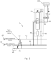
- a schematic diagram of the hydraulic system 1 is shown in Fig. 1 .
- the hydraulic system 1 is provided on a work machine (not shown).
- the hydraulic system 1 is provided to supply hydraulic fluid to a worktool 100 in order to drive the worktool 100.
- the hydraulic lines of the worktool 100 are configured to be connected to the first and second worktool ports 22, 32.
- the first and second worktool ports 22, 32 may be configured to attach to the hydraulic lines of the worktool 100 using a suitable connector.
- the first and second hydraulic ports 22, 32 are connected to first and second worktool lines 20, 30 respectively.
- the first and second worktool lines 20, 30 are connected between the spool valve 10 and the first and second worktool ports 22, 32 to supply hydraulic fluid.
- references to connections, or parts of the hydraulic system being connected are understood to mean fluidly connected for the purpose of transporting hydraulic fluid.
- the first and second worktool lines 20, 30 supply hydraulic fluid to the worktool 100 via the first and second worktool ports 22, 32 in order to operate the worktool 100.
- hydraulic fluid may be supplied to a cylinder of a worktool 100 in order to actuate the cylinder.
- hydraulic fluid may flow from the hydraulic system 1 to the worktool 100 via one of the first and second hydraulic lines 20, 30 and return to the hydraulic system 1 from the worktool 100 via the other of the first and second hydraulic lines 20, 30.
- the high pressure flow source of hydraulic fluid 40 provides a source of pressurised hydraulic fluid for the operation of the worktool 100.
- the high pressure flow source of hydraulic fluid 40 is configured to provide hydraulic fluid for one worktool 100.
- the high pressure flow source of hydraulic fluid 40 may be configured to provide a source of pressurised hydraulic fluid to a plurality of worktools 100 and/or other hydraulically actuated components of the work machine.
- the high pressure flow source of hydraulic fluid 40 is configurable to provide no flow of hydraulic fluid to the spool valve 10 while the power source of the work machine is still in operation.
- the high pressure flow source of hydraulic fluid 40 may be provided by a variable displacement pump (not shown). The variable displacement pump may be destroked in order to provide substantially zero flow of hydraulic fluid.
- the high pressure flow source of hydraulic fluid 40 is connected to the spool valve 10 by a high pressure line 42.
- the high pressure flow source of hydraulic fluid 40 may be configured to provide hydraulic fluid at a pressure suitable for operation of the desired worktool 100.
- the high pressure flow source of hydraulic fluid 40 may supply hydraulic fluid at a pressure of at least 100 bar, or at least 500 bar, although in other embodiments other pressures may be provided.
- the low pressure tank line 50 is a hydraulic line which is maintained at a pressure which is lower than the pressure in the high pressure line connected to the high pressure flow source of hydraulic fluid 50.
- the low pressure tank line 50 is at a pressure of at least 1 bar.
- the low pressure tank line may be at a pressure of no greater than 10 bar.
- the low pressure tank line may be at a pressure of no greater than 15 bar.
- the low pressure tank line may be at a pressure of about 5 bar.
- the low pressure tank line 50 may be configured to provide a return line for hydraulic fluid as part of the operation of the worktool 100.
- the low pressure tank line 50 may be further connected to a hydraulic reservoir 60 via a reservoir pressure valve 70 (tank pressure valve).
- the hydraulic reservoir 60 comprises hydraulic fluid which is maintained at a lower pressure than the low pressure tank line 50.
- the hydraulic reservoir 60 may be held at substantially atmospheric pressure.
- the reservoir pressure valve 70 may be provided between the low pressure tank line 50 and the hydraulic reservoir.
- the reservoir pressure valve 70 may be configured to control the flow (i.e. block or allow flow) of hydraulic fluid from the low pressure tank line 50 to the hydraulic reservoir by operation of the reservoir pressure valve 70.
- the reservoir pressure valve When the reservoir pressure valve is operated to open the reservoir pressure valve, the pressure of the hydraulic fluid in the low pressure tank line 50 may be reduced to about the same pressure as the pressure in the hydraulic reservoir 60.
- a spool valve 10 is provided.
- the spool vale 10 is connected to the first and second hydraulic lines 20, 30, and to the high pressure flow source of hydraulic fluid 40 and the low pressure tank line 50.
- the spool valve 10 is configured to connect the first worktool line 20 to one of the high pressure flow source of hydraulic fluid 40 and the low pressure tank line 50, wherein the second worktool line 30 is connected to the other of the high pressure flow source of hydraulic fluid 40 and the low pressure tank line 50.
- the spool valve 10 can be controlled to be in one of three positions: a blocking position, a first position, or a second position.
- the spool valve is in the blocking position.
- the high pressure flow source of hydraulic fluid 40 and the low pressure tank line 50 are not fluidly connected to the first and second worktool lines 20, 30.
- the spool valve 10 is in the blocking positon it is not possible for hydraulic fluid to flow from the high pressure flow source of hydraulic fluid 40 to the worktool 100.
- the first worktool port 22 When the spool valve is in the first position, the first worktool port 22 is connected to the low pressure tank line 50 via the first worktool line 20. In the second position, the second worktool port 32 is connected to the high pressure flow source 40 via the second worktool line 30.
- a diagram of the spool valve in the first position is shown in Fig. 2 .
- the second worktool port 32 When the spool valve 10 is in the second position, the second worktool port 32 is connected to the low pressure tank line 50 via the second worktool line 30. In the second position, the first worktool port 22 is connected to the high pressure flow source 40 via the first worktool line 20.
- the spool valve 10 may be configured to control the flow of hydraulic fluid to the worktool 100 in order to operate an actuator of the worktool 100.
- the spool valve 10 may be controlled to move between the blocking position, the first position, and the second position using a controller.
- the spool valve 10 is a pilot-operated spool valve.
- a pilot pressure supply 15 is used to move the spool valve 10 between the blocking position, the first position, and the second position.
- the pilot pressure supply to the spool valve 10 is controlled by first and second pressure reducing valves 80, 82.
- the first and second pressure reducing valves 80, 82 are electrically controlled valves configured to control the pressure on either side of the spool valve 10.
- a controller can be used to control the position of the spool valve 10. While in the embodiment of Fig. 1 a pilot pressure supply is used as an interface between the controller and the spool valve 10, in other embodiments other types of valve may be used where the spool valve position is directly controlled by electrical actuators (e.g. solenoids).
- the reservoir pressure valve 70 may also be a pilot operated valve.
- the reservoir pressure valve 70 may be controlled by a pilot pressure.
- the pilot pressure supplied to reservoir pressure valve 72 may in turn be controlled by tank pressure valve 72.
- Tank pressure valve 72 may be a further spool valve which controls a position (open or closed) of the reservoir pressure valve 70.
- tank pressure valve 72 is a three way, 2 position spool valve.
- the pilot pressure control for reservoir pressure valve 70 may be connected to either the pilot pressure supply or the hydraulic reservoir 60.
- the controller may be configured to control the position of the tank pressure valve 72.
- the reservoir pressure valve 70 may also be controlled by the controller via the pilot pressure supply.
- a source of power for the pilot pressure supply is provided.
- the pilot pressure supply may be generated by the work machine, for example from the same pressure source as the source of high pressure flow 40 for the high pressure line 42.
- the processor (not shown) is configured to control the flow of hydraulic fluid to the worktool 100 in order to control the operation of the worktool 100.
- the controller may control the spool valve 10 in order to affect the flow and return of hydraulic fluid through the first and second worktool ports 22, 32 in order to control e.g. a hydraulic actuator of the worktool 100.
- the controller may issue an instruction to the spool valve 10 to cause a flow of hydraulic fluid in response to a command from an operator of the work machine to move the position of the hydraulic actuator of the worktool 100.
- the controller is also configured to perform a worktool disconnect routine.
- the worktool disconnect routine may be performed when a worktool 100 is connected to the hydraulic system 1, although it may also be performed at other times.
- Performing the worktool disconnect routine causes the pressure in the first and second worktool lines 20, 30 (and thus the pressure at the first and second worktool ports 22, 32) to be reduced. Reducing the pressure in the first and second worktool lines allows the worktool hydraulic lines to be more easily disconnected from the work machine.
- the pressure reducing functionality of the worktool disconnect routine may be used as part of a process of connecting a new worktool to the hydraulic system 1 of the work machine.
- the worktool disconnect routine may be performed to reduce the pressure in the first and second worktool lines 20, 30. By reducing the pressure in the worktool lines, it may be easier to make a connection between the hydraulic lines.
- first and second worktool ports 22, 32 may be easier to connect to the hydraulic lines of the worktool following performance of the worktool disconnect routine.
- the worktool disconnect routine may be initiated by an operator of the work machine. For example, an operator of the work machine may initiate the worktool disconnect routine using a button press or through a computer based user interface. In some embodiments, the worktool disconnect routine may be initiated by a user triggering a switch integrated into a coupling mechanism for the worktool 100. As such, the work machine may include a coupling mechanism for the worktool 100 comprising a switch configured to initiate the controller to perform a worktool disconnect routine upon activation.
- the work machine and the worktool Prior to commencement of the worktool disconnect routine, the work machine and the worktool is understood to not be in active use. As such, it is understood that the worktool is essentially stationary, and as such the spool valve 10 is in the blocking position.
- the controller is configured to check that a power source of the work machine is operating.
- the worktool disconnect routine involves the operation of the spool valve 10 for which a supply of power is used. If the power source of the work machine is not operating, the controller does not allow the worktool disconnect routine to proceed.
- the power source of the work machine for the hydraulic system may be an internal combustion engine, a battery/motor (electrical power) or a hybrid power source (internal combustion engine and motor).
- the power source of the work machine may be used to provide power for controlling the spool valve and also to provide power for the operation of the high pressure supply of hydraulic fluid 40.
- the hydraulic system 1 may have a dedicated power source, or the hydraulic system 1 may share the power source of the work machine with other components of the work machine.
- a check may be performed that the spool valve 10 is in the blocking position and, in an event that the spool valve 10 is not in the blocking position, subsequent steps of the worktool disconnect routine may be prevented until such time as the spool valve 10 is in the blocking position.
- the controller is configured to instruct the high pressure flow source of hydraulic fluid 40 to provide no flow of hydraulic fluid to the spool valve 10.
- the controller destrokes the variable displacement pump to provide no flow of hydraulic fluid to the spool valve 10.
- the controller instructs the spool valve to move to the first position.
- the first worktool port 22 is connected to the low pressure tank line 50 such that the pressure in the first worktool line 20 is reduced.
- the spool valve 10 moves to the first position to reduce the pressure in the first worktool line 20 to the pressure in the low pressure tank line 50.
- the controller is configured to instruct the spool valve 10 to move to the first position for a time period of no greater than 500 ms. Following the move to the first position, the spool valve 10 may return to the blocking position.
- Fig. 2 shows a schematic diagram of the hydraulic lines being reduced in pressure (highlighted) when the spool valve 10 is in the first position.
- the controller instructs the spool valve 10 to move to the second position wherein the second worktool port 32 is connected to the low pressure tank line 50 and the first worktool port 22 is connected to the high pressure flow source in order to reduce a pressure in the second worktool line 30.
- the controller is configured to instruct the spool valve to move to the second position for a time period of no greater than 500 ms. Following the move to the second position, the spool valve 10 may return to the blocking position. By only moving to the second position for a limited period of time (no greater than 500 ms), sufficient time is provided to reduce the pressure in the second worktool line 20 without providing time for any significant flow of hydraulic fluid.
- Hydraulic fluid does not flow significantly while the spool valve 10 is in the second position because the high pressure flow source of hydraulic fluid 40 is instructed to provide no flow. Also, in the embodiment of Fig. 1 , the spool valve 10 is only in the second position for a limited time. Thus, the worktool actuator connected to the hydraulic system 1 does not substantially move as part of the worktool disconnect routine.
- the first and/or second positions of the spool valve 10 may be set by the controller based on a desired cross-sectional area. That is to say, the controller may control the degree to which the spool valve opens when moving to the first and/or second positions.
- the first and/or second positions for the worktool disconnect routine may involve the spool valve being only partially open (i.e. not fully open).
- the desired cross-sectional area of the opening of the spool valve in the first and/or second positions will depend on the size of the spool valve 10.
- the desired cross sectional area may also depend on the time the spool valve 10 is to remain in the first and/or second positions.
- the desired cross-sectional area may also depend on the degree of pressure reduction to be performed by the worktool disconnect routine.
- the desired cross sectional area of the spool valve opening in the first and/or second positions may be no greater than 90 % of the maximum opening cross-sectional area of the spool valve 10.
- the desired cross sectional area of the spool valve opening in the first and/or second positions may be no greater than: 70 %, 50 %, 40 %, 30 %, 20 %, 10 %, or 5 % of the maximum opening.
- the first and second positions of the spool valve may have different desired opening cross-sectional areas.
- Fig. 3 shows a schematic diagram of the hydraulic lines being reduced in pressure (highlighted) when the spool valve 10 is in the second position.
- the controller may instruct the spool valve 10 to move to the first position followed by the second position, whereas in other embodiments, the controller may instruct the spool valve 10 to move to the second position followed by the first position.
- the controller may also operate the reservoir pressure valve 70 to connect the low pressure tank line to the hydraulic reservoir when the spool valve is in the first position or the second position as part of the worktool disconnect routine.
- the pressure of the low pressure tank line is further reduced (e.g. to substantially atmospheric pressure).
- the pressure in the first and second worktool lines 20, 30 may be further reduced to allow for easier disconnection of the hydraulic lines of the worktool 100.
- a method may be provided by which trapped pressure in the first and second worktool lines 20, 30 is automatically reduced.
- the controller provides a controlled process for reducing the pressure which does not require operator involvement.
- the process may be controlled to reduce pressure in the first and second lines which does not result in substantial, unnecessary movement of the worktool actuator.
- the worktool disconnect routine can be integrated into a work machine without the use of additional valves and external lines for releasing pressure in the first and second worktool lines 20,30.
- a hydraulic system 2 is provided.
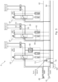
- a schematic diagram of the hydraulic system 2 is shown in Fig. 4 .
- the hydraulic system 2 of Fig. 4 comprises a plurality of spool valves 10.
- Each spool valve is of a similar construction to the spool valve 10 of Fig. 1 .
- Each spool valve 10 controls the flow of hydraulic fluid to a pair of worktool ports 22, 32.
- Each spool valve 10 is connected to the high pressure flow source of hydraulic fluid 40 via high pressure line 42.
- Each spool valve 10 is also connected to the low pressure tank line 40.
- the controller may be configured to perform the worktool disconnect routine for each of the plurality of spool valves 10.
- the controller may perform the worktool disconnect routine as described above for each spool valve at the same time, or sequentially.
- the controller may be provided to reduce the pressure in number of worktool lines to aid the disconnection of one or more worktools.
- the controller may specify that the worktool disconnect routine is to be performed on only some, or all of the worktool lines.
- a tank valve 90 is also provided for one of the spool valves 10.
- the tank valve 90 is connected between the first worktool line 20 and the hydraulic reservoir 60.
- Such a tank valve 90 may be provided in some hydraulic systems, but not in others (e.g. Fig. 1 ).
- the tank valve 90 controls a connection between the first worktool line 20 and the hydraulic reservoir 60.
- the tank valve 90 is connected between the reservoir pressure valve 70 and the first worktool line 20.
- the tank valve 90 is configured to be normally closed during normal operation.
- the tank valve 90 may be controlled by the controller to open in order to connect the first worktool line 20 to the hydraulic reservoir.
- the controller may operate the tank valve to connect the first worktool line to the hydraulic reservoir when the spool valve 10 is in the first position.
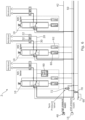
- Fig. 5 shows a schematic diagram of the hydraulic lines being reduced in pressure (highlighted) when the spool valves 10 are in the first position.
- the tank valve 90 is opened at the same time as the spool valve 10 is in the first position.
- Fig. 6 shows a schematic diagram of the hydraulic lines being reduced in pressure when the spool valves 10 are in the second position.
- the tank valve 90 s closed when the spool valve is in the second positon.
- the controller may control the spool valves 10 of the further embodiment to reduce pressure in a plurality of worktool lines connected to one or more worktools 100 to assist in the disconnection of the worktool(s) 100.
- the controller of the embodiments of this invention is configured to provide a worktool disconnect routine for a hydraulic system 1, 2 of a work machine.
- the worktool disconnect routine is provided to reduce pressure in hydraulic lines connecting the hydraulic system to the worktool 100 to assist in a processing of detaching the worktool 100 from the work machine.
- the controller or hydraulic system of this disclosure may be provided on a work machine such as a tractor, an excavator, a wheel loader or a compactor.
Landscapes
- Engineering & Computer Science (AREA)
- General Engineering & Computer Science (AREA)
- Mining & Mineral Resources (AREA)
- Civil Engineering (AREA)
- Structural Engineering (AREA)
- Mechanical Engineering (AREA)
- Physics & Mathematics (AREA)
- Fluid Mechanics (AREA)
- Chemical & Material Sciences (AREA)
- Analytical Chemistry (AREA)
- Fluid-Pressure Circuits (AREA)
- Shovels (AREA)
- Component Parts Of Construction Machinery (AREA)
- Fluid-Driven Valves (AREA)
- Operation Control Of Excavators (AREA)
Description
- The present invention relates to hydraulic systems. In particular the present invention relates to hydraulic systems for worktools.
- Work machines may include one or more interchangeable hydraulically-driven implements (worktools). By altering the worktool attached to the work machine, the function of the work machine can be altered. For example, a worktool for a work machine may include an auger, a bucket, a fork, a hammer, a mulcher, a broom, a demolition tool, a tiltrotator or the like.
- In order to provide the interchangeable functionality of a worktool, it must be possible to disconnect each worktool from a work machine and install another worktool. Part of the process of disconnecting the worktool includes disconnecting the hydraulic lines of the worktool from the hydraulic lines of the work machine which supply hydraulic fluid to the worktool.
- It is known that opening a closed hydraulic system can be difficult, and may be undesirable when the system is under high pressure. As such, attempting to disconnect the hydraulic lines of a worktool from the hydraulic lines of a work machine when under high pressure can be difficult. Furthermore, attempting to connect the hydraulic lines of the worktool to be connected to the hydraulic lines of the work machine may also be difficult when the hydraulic lines of the work machine are under high pressure.
-
US 6318234 discloses a line vent arrangement for an electro-hydraulic circuit. -
US 2007/261403 discloses a method and device for releasing residual pressure from a hydraulic system. -
US 2016/348799 discloses a decompression block assembly for coupling a source of hydraulic pressure to a hydraulically operated attachment. -
EP 2362023 discloses a hydraulic drive system for construction machine. -
EP 1239208 discloses an electrohydraulic circuit for relieving the pressure of quick-connect couplings. - According to a first aspect of the invention a controller for hydraulic system of a work machine is provided. The controller is configured to perform a worktool disconnect routine to reduce pressure in a first worktool line and a second worktool line of the hydraulic system. The hydraulic system comprises a spool valve, a first worktool port connected to the spool valve by the first worktool line, a second worktool port connected to the spool valve by the second worktool line, a high pressure flow source of hydraulic fluid connected to the spool valve by a high pressure line, and a low pressure tank line connected to the spool valve, the low pressure tank line at a lower pressure than a pressure of the high pressure line. When performing the worktool disconnect routine the controller is configured to:
- check that a power source of the work machine is operating;
- instruct the high pressure flow source of hydraulic fluid to provide no flow of hydraulic fluid in the high pressure line to the spool valve;
- instruct the spool valve to move to a first position wherein the first worktool port is connected to the low pressure tank line and the second worktool port is connected to the high pressure flow source in order to reduce a pressure in the first worktool line; and
- instruct the spool valve to move to a second position wherein the second worktool port is connected to the low pressure tank line and the first worktool port is connected to the high pressure flow source in order to reduce a pressure in the second worktool line. Accordingly, the controller of the first aspect is able to automatically reduce the pressure in first and second worktool lines of a work machine to enable a worktool to be disconnected from a work machine. The controller is configured to perform a worktool disconnect routine using the hydraulic system which, in normal use, is provided to control the supply of hydraulic fluid to the worktool. As such, the controller of the present invention provides additional functionality to a hydraulic system (the worktool disconnect routine) to allow a worktool to be more easily disconnected. Accordingly, the worktool disconnect routine may provide a pressure reducing functionality for the purposes of disconnecting a worktool from a hydraulic system of a work machine without any additional valves or auxiliary components which may not be used during a normal use of the hydraulic system/worktool.
- According to this invention, the worktool disconnect routine performed by the controller is understood to be a process which reduces pressure in the first and second worktool lines of the hydraulic system. As such, the skilled person understands that the worktool disconnect routine may be performed as part of a process for disconnecting a worktool, but is not limited to only such processes. The skilled person understands that the worktool disconnect routine may be used for other processes, for example connecting a new worktool to the hydraulic system of the work machine. That is to say, the worktool disconnect routine may be performed to reduce the pressure in the first and second worktool lines prior to the connecting the first and second lines to hydraulic lines of a new worktool. By reducing the pressure in the first and second hydraulic lines, it may be easier to connect the hydraulic lines together, thereby improving the lifetime of the connectors for the hydraulic lines.
- The controller of the first aspect allows the pressure to be reduced in the first and second worktool lines in a controlled manner without any further requirement for operator intervention. The movement of the spool valve can be controlled precisely by the controller. This in turn ensures, for example, that any worktool actuators connected to the first and second worktool lines do not excessively move during the worktool disconnect operation. Thus, the controller of the first aspect provides a way of reducing pressure in the hydraulic system with improved safety.
- In some embodiments, the worktool disconnect routine performed by the controller may be initiated by an operator of the work machine. For example, an operator of the work machine may initiate the worktool disconnect routine using a button press, or through a computer based user interface. In some embodiments, the worktool disconnect routine may be initiated by a user triggering a switch in communication with a coupling mechanism for the worktool.
- Smart couplers, quick couplers and the like provide for a work machine operator coupling the work machine with a worktool or decoupling the work machine from the worktool without having to leave the machine's cab, operator seat and/or the like. Instead, the machine operator, which may be a processor for an automated machine, initiates a coupling/decoupling operation from inside the machine. Smart couplers, quick couplers and the like generally include safety mechanisms to prevent inadvertent activation of the coupler and/or activation of the coupler when the worktool and/or the work machine are in operating modes where coupling/de-coupling is dangerous. As such, in some embodiments the controller may be configured to receive a signal from a smart coupling mechanism for the worktool when a disconnect/connect routine of the smart coupling mechanism is initiated and may process the pressure reduction prior to the rest of the coupling/de-coupling routine. Additionally, in some embodiments, the pressure reduction may only be activated by the controller if the safety mechanisms of the smart coupling mechanism determines that the worktool/work machine are in operating modes where it is safe to proceed with the coupling/de-coupling routine. In some embodiments, the operation of the smart coupling mechanism may include processing that the reduction in pressure has been initiated and a delay time in the coupling/de-coupling procedure is provided to allow for pressure reduction in the hydraulic system. In some embodiments, a sensor in the hydraulic system may be used to detect the reduction in pressure in the hydraulic system.
- According to a second aspect of the invention, a hydraulic system for a work machine having a power source is provided. The hydraulic system comprises:
- a spool valve;
- a first worktool line and a second worktool line;
- a first worktool port connected to the spool valve by the first worktool line;
- a second worktool port connected to the spool valve by the second worktool line;
- a high pressure flow source of hydraulic fluid connected to the spool valve by a high pressure line;
- a low pressure tank line connected to the spool valve, the low pressure tank line at a lower pressure than a pressure of the high pressure line; and
- a controller configured to perform a worktool disconnect routine to reduce pressure in a first worktool line and a second worktool line of the hydraulic system. The controller is configured to:
- check that the power source of the work machine is operating;
- instruct the high pressure flow source of hydraulic fluid to provide no flow of hydraulic fluid in the high pressure line to the spool valve;
- instruct the spool valve to move to a first position wherein the first worktool port is connected to the low pressure tank line and the second worktool port is connected to the high pressure flow source in order to reduce a pressure in the first worktool line; and
- instruct the spool valve to move to a second position wherein the second worktool port is connected to the low pressure tank line and the first worktool port is connected to the high pressure flow source in order to reduce a pressure in the second worktool line.
- As such, the hydraulic system of the second aspect is configured to perform the worktool disconnect routine in addition to the normal operations of a work machine.
- According to a third aspect of the invention, a work machine comprising a hydraulic system according to the second aspect of the invention is provided, wherein the work machine is one of a tractor, an excavator, a wheel loader or a compactor.
- Embodiments of the invention will now be described, by way of example only, with reference to the accompanying drawings in which:
-
Figure 1 shows a schematic diagram of a hydraulic system of a work machine according to an embodiment of the invention; -
Figure 2 shows a schematic diagram of a hydraulic system ofFig. 1 where the spool valve is in the first position; -
Figure 3 shows a schematic diagram of a hydraulic system ofFig. 1 where the spool valve is in the second position; -
Figure 4 shows a schematic diagram of a hydraulic system of a work machine according to a further embodiment of the invention; -
Figure 5 shows a schematic diagram of a hydraulic system ofFig. 4 where each of the spool valves are in the first position; -
Figure 6 shows a schematic diagram of a hydraulic system ofFig. 4 where each of the spool valves are in the second position. - According to an embodiment of the invention, a
hydraulic system 1 for a work machine is provided. Thehydraulic system 1 comprises: aspool valve 10, afirst worktool line 20, asecond worktool line 30, afirst worktool port 22, asecond worktool port 32, a high pressure flow source ofhydraulic fluid 40, a lowpressure tank line 50 and a controller (not shown). A schematic diagram of thehydraulic system 1 is shown inFig. 1 . - The
hydraulic system 1 is provided on a work machine (not shown). Thehydraulic system 1 is provided to supply hydraulic fluid to aworktool 100 in order to drive theworktool 100. The hydraulic lines of theworktool 100 are configured to be connected to the first andsecond worktool ports second worktool ports worktool 100 using a suitable connector. The first and secondhydraulic ports second worktool lines second worktool lines spool valve 10 and the first andsecond worktool ports second worktool lines worktool 100 via the first andsecond worktool ports worktool 100. For example, hydraulic fluid may be supplied to a cylinder of aworktool 100 in order to actuate the cylinder. When actuating a cylinder, hydraulic fluid may flow from thehydraulic system 1 to theworktool 100 via one of the first and secondhydraulic lines hydraulic system 1 from theworktool 100 via the other of the first and secondhydraulic lines - The high pressure flow source of
hydraulic fluid 40 provides a source of pressurised hydraulic fluid for the operation of theworktool 100. In the embodiment ofFig. 1 , the high pressure flow source ofhydraulic fluid 40 is configured to provide hydraulic fluid for oneworktool 100. In other embodiments, the high pressure flow source ofhydraulic fluid 40 may be configured to provide a source of pressurised hydraulic fluid to a plurality ofworktools 100 and/or other hydraulically actuated components of the work machine. - In the embodiment of
Fig. 1 , the high pressure flow source ofhydraulic fluid 40 is configurable to provide no flow of hydraulic fluid to thespool valve 10 while the power source of the work machine is still in operation. In the embodiment ofFig. 1 , the high pressure flow source ofhydraulic fluid 40 may be provided by a variable displacement pump (not shown). The variable displacement pump may be destroked in order to provide substantially zero flow of hydraulic fluid. As shown inFig. 1 , the high pressure flow source ofhydraulic fluid 40 is connected to thespool valve 10 by ahigh pressure line 42. In the embodiment ofFig. 1 the high pressure flow source ofhydraulic fluid 40 may be configured to provide hydraulic fluid at a pressure suitable for operation of the desiredworktool 100. For example, in some embodiments, the high pressure flow source ofhydraulic fluid 40 may supply hydraulic fluid at a pressure of at least 100 bar, or at least 500 bar, although in other embodiments other pressures may be provided. - In the embodiment of
Fig. 1 , the lowpressure tank line 50 is a hydraulic line which is maintained at a pressure which is lower than the pressure in the high pressure line connected to the high pressure flow source ofhydraulic fluid 50. In the embodiment ofFig. 1 , the lowpressure tank line 50 is at a pressure of at least 1 bar. In some embodiments, the low pressure tank line may be at a pressure of no greater than 10 bar. In some embodiments, the low pressure tank line may be at a pressure of no greater than 15 bar. - In the embodiment of
Fig. 1 , the low pressure tank line may be at a pressure of about 5 bar. In normal operation, the lowpressure tank line 50 may be configured to provide a return line for hydraulic fluid as part of the operation of theworktool 100. - In some embodiments, for example as shown in
Fig. 1 , the lowpressure tank line 50 may be further connected to ahydraulic reservoir 60 via a reservoir pressure valve 70 (tank pressure valve). Thehydraulic reservoir 60 comprises hydraulic fluid which is maintained at a lower pressure than the lowpressure tank line 50. For example, in some embodiments, thehydraulic reservoir 60 may be held at substantially atmospheric pressure. - The
reservoir pressure valve 70 may be provided between the lowpressure tank line 50 and the hydraulic reservoir. Thereservoir pressure valve 70 may be configured to control the flow (i.e. block or allow flow) of hydraulic fluid from the lowpressure tank line 50 to the hydraulic reservoir by operation of thereservoir pressure valve 70. When the reservoir pressure valve is operated to open the reservoir pressure valve, the pressure of the hydraulic fluid in the lowpressure tank line 50 may be reduced to about the same pressure as the pressure in thehydraulic reservoir 60. - In order to control the flow of hydraulic fluid from the
hydraulic system 1 to theworktool 100, aspool valve 10 is provided. Thespool vale 10 is connected to the first and secondhydraulic lines hydraulic fluid 40 and the lowpressure tank line 50. Thespool valve 10 is configured to connect thefirst worktool line 20 to one of the high pressure flow source ofhydraulic fluid 40 and the lowpressure tank line 50, wherein thesecond worktool line 30 is connected to the other of the high pressure flow source ofhydraulic fluid 40 and the lowpressure tank line 50. As such, thespool valve 10 can be controlled to be in one of three positions: a blocking position, a first position, or a second position. - In the diagram of
Fig. 1 , the spool valve is in the blocking position. When the spool valve is in the blocking position, the high pressure flow source ofhydraulic fluid 40 and the lowpressure tank line 50 are not fluidly connected to the first andsecond worktool lines spool valve 10 is in the blocking positon it is not possible for hydraulic fluid to flow from the high pressure flow source ofhydraulic fluid 40 to theworktool 100. - When the spool valve is in the first position, the
first worktool port 22 is connected to the lowpressure tank line 50 via thefirst worktool line 20. In the second position, thesecond worktool port 32 is connected to the highpressure flow source 40 via thesecond worktool line 30. A diagram of the spool valve in the first position is shown inFig. 2 . - When the
spool valve 10 is in the second position, thesecond worktool port 32 is connected to the lowpressure tank line 50 via thesecond worktool line 30. In the second position, thefirst worktool port 22 is connected to the highpressure flow source 40 via thefirst worktool line 20. - As such, in normal use (when a
worktool 100 is connected to the hydraulic system 1) thespool valve 10 may be configured to control the flow of hydraulic fluid to theworktool 100 in order to operate an actuator of theworktool 100. Thespool valve 10 may be controlled to move between the blocking position, the first position, and the second position using a controller. In the embodiment ofFig. 1 , thespool valve 10 is a pilot-operated spool valve. Apilot pressure supply 15 is used to move thespool valve 10 between the blocking position, the first position, and the second position. The pilot pressure supply to thespool valve 10 is controlled by first and secondpressure reducing valves pressure reducing valves spool valve 10. As such, a controller can be used to control the position of thespool valve 10. While in the embodiment ofFig. 1 a pilot pressure supply is used as an interface between the controller and thespool valve 10, in other embodiments other types of valve may be used where the spool valve position is directly controlled by electrical actuators (e.g. solenoids). - In the embodiment of
Fig. 1 , thereservoir pressure valve 70 may also be a pilot operated valve. Thereservoir pressure valve 70 may be controlled by a pilot pressure. The pilot pressure supplied toreservoir pressure valve 72 may in turn be controlled bytank pressure valve 72.Tank pressure valve 72 may be a further spool valve which controls a position (open or closed) of thereservoir pressure valve 70. As shown inFig. 1 ,tank pressure valve 72 is a three way, 2 position spool valve. The pilot pressure control forreservoir pressure valve 70 may be connected to either the pilot pressure supply or thehydraulic reservoir 60. The controller may be configured to control the position of thetank pressure valve 72. As such, thereservoir pressure valve 70 may also be controlled by the controller via the pilot pressure supply. As such, it will be appreciated that in order to control the valves of thehydraulic system 1 of the embodiment with a controller, a source of power for the pilot pressure supply is provided. The pilot pressure supply may be generated by the work machine, for example from the same pressure source as the source ofhigh pressure flow 40 for thehigh pressure line 42. - The processor (not shown) is configured to control the flow of hydraulic fluid to the
worktool 100 in order to control the operation of theworktool 100. In normal use of the work machine, the controller (processor) may control thespool valve 10 in order to affect the flow and return of hydraulic fluid through the first andsecond worktool ports worktool 100. As such, the controller may issue an instruction to thespool valve 10 to cause a flow of hydraulic fluid in response to a command from an operator of the work machine to move the position of the hydraulic actuator of theworktool 100. - According to embodiments of the invention, the controller is also configured to perform a worktool disconnect routine. The worktool disconnect routine may be performed when a
worktool 100 is connected to thehydraulic system 1, although it may also be performed at other times. Performing the worktool disconnect routine causes the pressure in the first andsecond worktool lines 20, 30 (and thus the pressure at the first andsecond worktool ports 22, 32) to be reduced. Reducing the pressure in the first and second worktool lines allows the worktool hydraulic lines to be more easily disconnected from the work machine. The pressure reducing functionality of the worktool disconnect routine may be used as part of a process of connecting a new worktool to thehydraulic system 1 of the work machine. Prior to connecting the hydraulic lines of the new worktool to the first andsecond worktool lines second worktool lines second worktool ports worktool 100. As such, the work machine may include a coupling mechanism for theworktool 100 comprising a switch configured to initiate the controller to perform a worktool disconnect routine upon activation. - Prior to commencement of the worktool disconnect routine, the work machine and the worktool is understood to not be in active use. As such, it is understood that the worktool is essentially stationary, and as such the
spool valve 10 is in the blocking position. - As part of an initial step of the worktool disconnect routine, the controller is configured to check that a power source of the work machine is operating. The worktool disconnect routine involves the operation of the
spool valve 10 for which a supply of power is used. If the power source of the work machine is not operating, the controller does not allow the worktool disconnect routine to proceed. In some embodiments, the power source of the work machine for the hydraulic system may be an internal combustion engine, a battery/motor (electrical power) or a hybrid power source (internal combustion engine and motor). The power source of the work machine may be used to provide power for controlling the spool valve and also to provide power for the operation of the high pressure supply ofhydraulic fluid 40. In some embodiments, thehydraulic system 1 may have a dedicated power source, or thehydraulic system 1 may share the power source of the work machine with other components of the work machine. - As part of the initial step of the worktool disconnect routine, a check may be performed that the
spool valve 10 is in the blocking position and, in an event that thespool valve 10 is not in the blocking position, subsequent steps of the worktool disconnect routine may be prevented until such time as thespool valve 10 is in the blocking position. - As part of the worktool disconnect routine, the controller is configured to instruct the high pressure flow source of
hydraulic fluid 40 to provide no flow of hydraulic fluid to thespool valve 10. In the embodiment ofFig. 1 , where the high pressure flow source ofhydraulic fluid 40 is a variable displacement pump, the controller destrokes the variable displacement pump to provide no flow of hydraulic fluid to thespool valve 10. - Next, the controller instructs the spool valve to move to the first position. By moving the spool valve to the first position, the
first worktool port 22 is connected to the lowpressure tank line 50 such that the pressure in thefirst worktool line 20 is reduced. In some embodiments, thespool valve 10 moves to the first position to reduce the pressure in thefirst worktool line 20 to the pressure in the lowpressure tank line 50. In some embodiments, the controller is configured to instruct thespool valve 10 to move to the first position for a time period of no greater than 500 ms. Following the move to the first position, thespool valve 10 may return to the blocking position. By only moving to the first position for a limited period of time (no greater than 500 ms), sufficient time is provided to reduce the pressure in thefirst worktool line 20 without providing time for any significant flow of hydraulic fluid. Hydraulic fluid does not flow significantly while thespool valve 10 is in the first position because the high pressure flow source ofhydraulic fluid 40 is instructed to provide no flow. Also, in the embodiment ofFig. 1 , thespool valve 10 is only in the first position for a limited time. Thus, a worktool actuator connected to thehydraulic system 1 does not substantially move as part of the worktool disconnect routine. -
Fig. 2 shows a schematic diagram of the hydraulic lines being reduced in pressure (highlighted) when thespool valve 10 is in the first position. - Next, the controller instructs the
spool valve 10 to move to the second position wherein thesecond worktool port 32 is connected to the lowpressure tank line 50 and thefirst worktool port 22 is connected to the high pressure flow source in order to reduce a pressure in thesecond worktool line 30. In some embodiments, the controller is configured to instruct the spool valve to move to the second position for a time period of no greater than 500 ms. Following the move to the second position, thespool valve 10 may return to the blocking position. By only moving to the second position for a limited period of time (no greater than 500 ms), sufficient time is provided to reduce the pressure in thesecond worktool line 20 without providing time for any significant flow of hydraulic fluid. Hydraulic fluid does not flow significantly while thespool valve 10 is in the second position because the high pressure flow source ofhydraulic fluid 40 is instructed to provide no flow. Also, in the embodiment ofFig. 1 , thespool valve 10 is only in the second position for a limited time. Thus, the worktool actuator connected to thehydraulic system 1 does not substantially move as part of the worktool disconnect routine. - In some embodiments, the first and/or second positions of the
spool valve 10 may be set by the controller based on a desired cross-sectional area. That is to say, the controller may control the degree to which the spool valve opens when moving to the first and/or second positions. In some embodiments, the first and/or second positions for the worktool disconnect routine may involve the spool valve being only partially open (i.e. not fully open). The desired cross-sectional area of the opening of the spool valve in the first and/or second positions will depend on the size of thespool valve 10. The desired cross sectional area may also depend on the time thespool valve 10 is to remain in the first and/or second positions. The desired cross-sectional area may also depend on the degree of pressure reduction to be performed by the worktool disconnect routine. For example, some embodiments, the desired cross sectional area of the spool valve opening in the first and/or second positions may be no greater than 90 % of the maximum opening cross-sectional area of thespool valve 10. In some embodiments, the desired cross sectional area of the spool valve opening in the first and/or second positions may be no greater than: 70 %, 50 %, 40 %, 30 %, 20 %, 10 %, or 5 % of the maximum opening. In some embodiments, the first and second positions of the spool valve may have different desired opening cross-sectional areas. -
Fig. 3 shows a schematic diagram of the hydraulic lines being reduced in pressure (highlighted) when thespool valve 10 is in the second position. - It will be appreciated that in some embodiments, the controller may instruct the
spool valve 10 to move to the first position followed by the second position, whereas in other embodiments, the controller may instruct thespool valve 10 to move to the second position followed by the first position. - In some embodiments, for example in the embodiment of
Fig. 1 , the controller may also operate thereservoir pressure valve 70 to connect the low pressure tank line to the hydraulic reservoir when the spool valve is in the first position or the second position as part of the worktool disconnect routine. Thus, when the controller moves thespool valve 10 to the first and second positions as part of the worktool disconnect routine, the pressure of the low pressure tank line is further reduced (e.g. to substantially atmospheric pressure). As such, the pressure in the first andsecond worktool lines worktool 100. - As such, by providing a controller which performs a worktool disconnect routine, a method may be provided by which trapped pressure in the first and
second worktool lines second worktool lines - According to a further embodiment of the disclosure, a
hydraulic system 2 is provided. A schematic diagram of thehydraulic system 2 is shown inFig. 4 . It will be appreciated that thehydraulic system 2 ofFig. 4 has similarities to thehydraulic system 1 ofFig. 1 . Like reference numerals are used to indicate similar parts. Thehydraulic system 2 ofFig. 4 comprises a plurality ofspool valves 10. Each spool valve is of a similar construction to thespool valve 10 ofFig. 1 . Eachspool valve 10 controls the flow of hydraulic fluid to a pair ofworktool ports spool valve 10 is connected to the high pressure flow source ofhydraulic fluid 40 viahigh pressure line 42. Eachspool valve 10 is also connected to the lowpressure tank line 40. - The controller (not shown) may be configured to perform the worktool disconnect routine for each of the plurality of
spool valves 10. The controller may perform the worktool disconnect routine as described above for each spool valve at the same time, or sequentially. Thus, the controller may be provided to reduce the pressure in number of worktool lines to aid the disconnection of one or more worktools. The controller may specify that the worktool disconnect routine is to be performed on only some, or all of the worktool lines. - In the embodiment of
Fig. 4 , atank valve 90 is also provided for one of thespool valves 10. Thetank valve 90 is connected between thefirst worktool line 20 and thehydraulic reservoir 60. Such atank valve 90 may be provided in some hydraulic systems, but not in others (e.g.Fig. 1 ). As such, thetank valve 90 controls a connection between thefirst worktool line 20 and thehydraulic reservoir 60. Effectively, thetank valve 90 is connected between thereservoir pressure valve 70 and thefirst worktool line 20. Thetank valve 90 is configured to be normally closed during normal operation. During the worktool disconnect routine, thetank valve 90 may be controlled by the controller to open in order to connect thefirst worktool line 20 to the hydraulic reservoir. Where atank valve 90 is provided, the controller may operate the tank valve to connect the first worktool line to the hydraulic reservoir when thespool valve 10 is in the first position. -
Fig. 5 shows a schematic diagram of the hydraulic lines being reduced in pressure (highlighted) when thespool valves 10 are in the first position. In the diagram ofFig. 5 , thetank valve 90 is opened at the same time as thespool valve 10 is in the first position. -
Fig. 6 shows a schematic diagram of the hydraulic lines being reduced in pressure when thespool valves 10 are in the second position. In the diagram ofFig. 6 , the tank valve 90 s closed when the spool valve is in the second positon. - Thus, the controller may control the
spool valves 10 of the further embodiment to reduce pressure in a plurality of worktool lines connected to one or more worktools 100 to assist in the disconnection of the worktool(s) 100. - The controller of the embodiments of this invention is configured to provide a worktool disconnect routine for a
hydraulic system worktool 100 to assist in a processing of detaching theworktool 100 from the work machine. - The controller or hydraulic system of this disclosure may be provided on a work machine such as a tractor, an excavator, a wheel loader or a compactor.
Claims (15)
- A controller for hydraulic system (1) of a work machine, the controller configured to perform a worktool disconnect routine to reduce pressure in a first worktool line (20) and a second worktool line (30) of the hydraulic system,wherein the hydraulic system (1) comprises:a spool valve (10);a first worktool port (22) connected to the spool valve (10) by the first worktool line (20);a second worktool port (32) connected to the spool valve (10) by the second worktool line (30);a high pressure flow source of hydraulic fluid (40) connected to the spool valve (10) by a high pressure line (42);a low pressure tank line (50) connected to the spool valve (10), the low pressure tank line (50) at a lower pressure than a pressure of the high pressure line (42);wherein when performing the worktool disconnect routine the controller is configured to:check that a power source of the work machine is operating;instruct the high pressure flow source of hydraulic fluid (40) to provide no flow of hydraulic fluid in the high pressure line (42) to the spool valve (10);instruct the spool valve (10) to move to a first position wherein the first worktool port (22) is connected to the low pressure tank line (50) and the second worktool port (32) is connected to the high pressure flow source (42) in order to reduce a pressure in the first worktool line (20); andinstruct the spool valve (10) to move to a second position wherein the second worktool port (32) is connected to the low pressure tank line (50) and the first worktool port (22) is connected to the high pressure flow source (40) in order to reduce a pressure in the second worktool line (32).
- A controller according to claim 1, whereinthe controller is configured to instruct the spool valve (10) to move to the first position for a time period of no greater than 500 ms; and/orthe controller is configured to instruct the spool valve (10) to move to the second position for a time period of no greater than 500 ms.
- A controller according to claim 1 or claim 2, wherein
the hydraulic system (1) comprises a hydraulic reservoir (60) connected to the tank line (50), wherein the hydraulic reservoir (60) comprises hydraulic fluid at substantially atmospheric pressure, wherein optionally:the low pressure tank line (50) is connected to the hydraulic reservoir (60) by a reservoir pressure valve (70), andwherein the controller is configured to operate the reservoir pressure valve (70) to connect the low pressure tank line (50) to the hydraulic reservoir (60) when the spool valve (10) is in the first position or the second position. - A controller according to any preceding claim, whereinthe hydraulic system (1) comprises a plurality of spool valves (10), each spool valve (10) connected to the high pressure flow source (40), the low pressure tank lines (50) and a pair of worktool ports (22, 32),wherein the controller is configured to perform the worktool disconnect routine for each of the spool valves (10).
- A controller according to any preceding claim, whereinthe controller is configured to initiate the worktool disconnect routine upon at least one of: a button press, an instruction from a computer based interface, a signal from a switch integrated into a coupling mechanism for the worktool; and/orthe controller is configured to perform the worktool disconnect routine as part of a process for connecting a worktool (100) to the work machine.
- A hydraulic system (1) for a work machine having a power source, the hydraulic system (1) comprising:a spool valve (10);a first worktool line (20) and a second worktool line (30);a first worktool port connected (22) to the spool valve (10) by the first worktool line (20);a second worktool port (32) connected to the spool valve (10) by the second worktool line (30);a high pressure flow source (40) of hydraulic fluid connected to the spool valve (10) by a high pressure line (42);a low pressure tank line (50) connected to the spool valve (10), the low pressure tank line (50) at a lower pressure than a pressure of the high pressure line (50);a controller configured to perform a worktool disconnect routine to reduce pressure in the first worktool line (20) and the second worktool line (30) of the hydraulic system (1), wherein the controller is configured to:check that the power source of the work machine is operating;instruct the high pressure flow source (40) of hydraulic fluid to provide no flow of hydraulic fluid in the high pressure line (42) to the spool valve (10);instruct the spool valve (10) to move to a first position wherein the first worktool port (22) is connected to the low pressure tank line (50) and the second worktool port (32) is connected to the high pressure flow source (40) in order to reduce a pressure in the first worktool line (20); andinstruct the spool valve (10) to move to a second position wherein the second worktool port (32) is connected to the low pressure tank line (50) and the first worktool port (22) is connected to the high pressure flow source (40) in order to reduce a pressure in the second worktool line (30).
- A hydraulic system (1) according to claim 6, whereinthe controller is configured to instruct the spool valve (10) to move to the first position for a time period of no greater than 500 ms; and/orthe controller is configured to instruct the spool valve (10) to move to the second position for a time period of no greater than 500 ms.
- A hydraulic system (1) according to claim 6 or claim 7, wherein
the hydraulic system (1) comprises a hydraulic reservoir (60) connected to the tank line (50), wherein the hydraulic reservoir (60) comprises hydraulic fluid at substantially atmospheric pressure, wherein optionally:the low pressure tank line (50) is connected to the hydraulic reservoir (60) by a reservoir pressure valve (70), andwherein the controller is configured to operate the reservoir pressure valve (70) to connect the low pressure tank line (50) to the hydraulic reservoir (60) when the spool valve (10) is in the first position or the second position. - A hydraulic system (1) according to any of claims 6 to 8, wherein
the high pressure flow source (40) of hydraulic fluid comprises a variable displacement pump, wherein the controller is configured to destroke the variable displacement pump to provide no flow of hydraulic fluid. - A hydraulic system (1) according to any of claims 6 to 9, whereinthe hydraulic system (1) further comprises a tank valve (90) connected between the first worktool line (20) and the low pressure tank line (50),wherein the controller is configured to operate the tank valve (90) to connect the first worktool line (20) to the low pressure tank line (50) when the spool valve (10) is in the first position.
- A hydraulic system (1) according to claim 10 when dependent on any of claims 8 to 9, wherein
the tank valve (90) is connected between the first worktool line (20) and the reservoir pressure valve (70) such that the first worktool line (20) is connected to the hydraulic reservoir (60) when the tank valve (90) is operated. - A hydraulic system (1) according to any of claims 6 to 11, whereinthe hydraulic system (1) comprises a plurality of spool valves (10), each spool valve (10) connected to the high pressure flow source (40), the low pressure tank line (50) and a pair of worktool ports (22, 32),wherein the controller is configured to perform the worktool disconnect routine for each of the spool valves (10).
- A hydraulic system (1) according to any of claims 6 to 12, wherein
the low pressure tank line (50) is at a pressure of at least 1 bar and no greater than 10 bar. - A hydraulic system (1) according to any of claims 6 to 13, whereinthe controller is configured to initiate the worktool disconnect routine upon at least one of: a button press, an instruction from a computer based interface, and a signal from a switch integrated into a coupling mechanism for the worktool and/orthe controller is configured to perform the worktool disconnect routine as part of a process for connecting a worktool (100) to the work machine.
- A work machine comprising a hydraulic system according to any of claims 6 to 14, wherein the work machine is one of a tractor, an excavator, a wheel loader or a compactor.
Applications Claiming Priority (3)
| Application Number | Priority Date | Filing Date | Title |
|---|---|---|---|
| GBGB2015847.3A GB202015847D0 (en) | 2020-10-06 | 2020-10-06 | Automatic pressure release |
| GB2017335.7A GB2599738B (en) | 2020-10-06 | 2020-11-02 | Automatic pressure release |
| PCT/EP2021/057829 WO2022073651A1 (en) | 2020-10-06 | 2021-03-25 | Automatic pressure release |
Publications (2)
| Publication Number | Publication Date |
|---|---|
| EP4226052A1 EP4226052A1 (en) | 2023-08-16 |
| EP4226052B1 true EP4226052B1 (en) | 2024-11-13 |
Family
ID=73223728
Family Applications (1)
| Application Number | Title | Priority Date | Filing Date |
|---|---|---|---|
| EP21716296.5A Active EP4226052B1 (en) | 2020-10-06 | 2021-03-25 | Automatic pressure release |
Country Status (8)
| Country | Link |
|---|---|
| US (1) | US12601149B2 (en) |
| EP (1) | EP4226052B1 (en) |
| JP (1) | JP7753352B2 (en) |
| CN (1) | CN116324188A (en) |
| AU (1) | AU2021355870A1 (en) |
| CA (1) | CA3195089A1 (en) |
| GB (2) | GB202015847D0 (en) |
| WO (1) | WO2022073651A1 (en) |
Citations (1)
| Publication number | Priority date | Publication date | Assignee | Title |
|---|---|---|---|---|
| EP1239208B1 (en) * | 2001-03-10 | 2005-12-14 | Deere & Company | Electrohydraulic circuit for relieving the pressure of quick-connect couplings |
Family Cites Families (22)
| Publication number | Priority date | Publication date | Assignee | Title |
|---|---|---|---|---|
| JP2588514B2 (en) | 1986-10-16 | 1997-03-05 | 東芝機械株式会社 | How to remove residual pressure from core cylinder hydraulic circuit |
| US6318234B1 (en) | 2000-06-30 | 2001-11-20 | Caterpillar Inc. | Line vent arrangement for electro-hydraulic circuit |
| JP4569940B2 (en) * | 2001-06-20 | 2010-10-27 | ヤンマー株式会社 | Backhoe hydraulic circuit |
| US6502500B2 (en) * | 2001-04-30 | 2003-01-07 | Caterpillar Inc | Hydraulic system for a work machine |
| US6837319B2 (en) * | 2002-07-29 | 2005-01-04 | Caterpillar S.A.R.L. | Control system for, and a method of, disengaging a hydraulically-driven implement from a work machine |
| US20070261403A1 (en) * | 2006-05-10 | 2007-11-15 | Eppler Craig T | Pressure shuttle |
| US8001751B2 (en) | 2007-09-14 | 2011-08-23 | Cnh America Llc | Method for gradually relieving pressure in a hydraulic system utilizing reverse fluid flow through a pump of the system |
| JP2011179191A (en) * | 2010-02-26 | 2011-09-15 | Hitachi Constr Mach Co Ltd | Hydraulic drive unit for construction machine |
| GB2486887A (en) | 2010-12-21 | 2012-07-04 | Miller Int Ltd | Quick coupler status alarm |
| US8863509B2 (en) * | 2011-08-31 | 2014-10-21 | Caterpillar Inc. | Meterless hydraulic system having load-holding bypass |
| US20140060034A1 (en) * | 2012-08-30 | 2014-03-06 | Capterpillar, Inc. | Electro-Hydraulic Control Design for Pump Discharge Pressure Control |
| US20160251830A1 (en) * | 2013-10-30 | 2016-09-01 | Young-Jin Son | Hydraulic system of construction equipment, having float function |
| US9194284B2 (en) * | 2014-02-28 | 2015-11-24 | Deere & Company | Reservoir pressurization |
| DE102014209387B3 (en) * | 2014-05-16 | 2015-09-24 | Rausch & Pausch Gmbh | hydraulic system |
| DE102014013495A1 (en) | 2014-09-09 | 2016-03-10 | Hydac Technology Gmbh | Device for pressure relief on hydraulic lines |
| US9790964B2 (en) * | 2014-09-25 | 2017-10-17 | Cnh Industrial America Llc | Hydraulic system |
| US9976659B2 (en) * | 2015-06-01 | 2018-05-22 | Holmbury, Ltd. | Decompression coupling block |
| JP2017187144A (en) | 2016-04-08 | 2017-10-12 | 株式会社竹内製作所 | Work machine |
| US10323458B2 (en) * | 2016-10-21 | 2019-06-18 | Caterpillar Inc. | Dual pressure logic for a track drill circuit |
| US11105063B2 (en) | 2017-02-28 | 2021-08-31 | Komatsu Ltd. | Quick coupler circuit and quick coupler attachment/detachment method |
| GB2569643B (en) | 2017-12-22 | 2021-04-14 | Bamford Excavators Ltd | Locking system for a working machine |
| US10550541B1 (en) * | 2019-04-25 | 2020-02-04 | Deere & Company | Connection system for connecting an implement to a work vehicle |
-
2020
- 2020-10-06 GB GBGB2015847.3A patent/GB202015847D0/en not_active Ceased
- 2020-11-02 GB GB2017335.7A patent/GB2599738B/en active Active
-
2021
- 2021-03-25 EP EP21716296.5A patent/EP4226052B1/en active Active
- 2021-03-25 AU AU2021355870A patent/AU2021355870A1/en active Pending
- 2021-03-25 CA CA3195089A patent/CA3195089A1/en active Pending
- 2021-03-25 CN CN202180067929.4A patent/CN116324188A/en active Pending
- 2021-03-25 WO PCT/EP2021/057829 patent/WO2022073651A1/en not_active Ceased
- 2021-03-25 JP JP2023519283A patent/JP7753352B2/en active Active
- 2021-03-25 US US18/028,624 patent/US12601149B2/en active Active
Patent Citations (1)
| Publication number | Priority date | Publication date | Assignee | Title |
|---|---|---|---|---|
| EP1239208B1 (en) * | 2001-03-10 | 2005-12-14 | Deere & Company | Electrohydraulic circuit for relieving the pressure of quick-connect couplings |
Also Published As
| Publication number | Publication date |
|---|---|
| GB202015847D0 (en) | 2020-11-18 |
| CN116324188A (en) | 2023-06-23 |
| EP4226052A1 (en) | 2023-08-16 |
| GB2599738B (en) | 2023-07-12 |
| GB2599738A (en) | 2022-04-13 |
| CA3195089A1 (en) | 2022-04-14 |
| JP2023544134A (en) | 2023-10-20 |
| AU2021355870A1 (en) | 2023-05-25 |
| US12601149B2 (en) | 2026-04-14 |
| WO2022073651A1 (en) | 2022-04-14 |
| GB202017335D0 (en) | 2020-12-16 |
| JP7753352B2 (en) | 2025-10-14 |
| US20230366177A1 (en) | 2023-11-16 |
Similar Documents
| Publication | Publication Date | Title |
|---|---|---|
| US7861642B2 (en) | Valve block, tool attachment, a working machine and the use of a valve block | |
| EP2696081B1 (en) | Hydraulic drive of machinery | |
| US10947699B2 (en) | Construction machine | |
| EP3129559A1 (en) | Quick coupler control device for working machine | |
| US6260357B1 (en) | Quick coupler control system | |
| CN110099816B (en) | System for assisting in driving a trailer from an open tipping hydraulic circuit | |
| US6837319B2 (en) | Control system for, and a method of, disengaging a hydraulically-driven implement from a work machine | |
| EP4522811B1 (en) | Universal hydraulic auxiliary depressurization circuit and method of depressurizing a work tool auxiliary circuit of a work machine | |
| WO2008085247A1 (en) | Freely rotatable closed grapple head and machine using same | |
| US12601149B2 (en) | Automatic pressure release | |
| US7559270B2 (en) | Hydraulic cylinder system | |
| US6318234B1 (en) | Line vent arrangement for electro-hydraulic circuit | |
| EP2931983B1 (en) | System and methods for controlled lowering and lifting of a load | |
| EP3814578B1 (en) | Method and system to securely manage quick coupling of tools in an earth moving equipment | |
| US20260076281A1 (en) | Arrangement for operating a hydraulic control valve for an agricultural tractor | |
| US7210395B2 (en) | System for handling a tool at a vehicle | |
| KR100448537B1 (en) | Method and apparatus for locking machine | |
| US20240384497A1 (en) | Construction Machine | |
| JPH0475502A (en) | Tractor hydraulic circuit switching valve device |
Legal Events
| Date | Code | Title | Description |
|---|---|---|---|
| STAA | Information on the status of an ep patent application or granted ep patent |
Free format text: STATUS: UNKNOWN |
|
| STAA | Information on the status of an ep patent application or granted ep patent |
Free format text: STATUS: THE INTERNATIONAL PUBLICATION HAS BEEN MADE |
|
| PUAI | Public reference made under article 153(3) epc to a published international application that has entered the european phase |
Free format text: ORIGINAL CODE: 0009012 |
|
| STAA | Information on the status of an ep patent application or granted ep patent |
Free format text: STATUS: REQUEST FOR EXAMINATION WAS MADE |
|
| 17P | Request for examination filed |
Effective date: 20230330 |
|
| AK | Designated contracting states |
Kind code of ref document: A1 Designated state(s): AL AT BE BG CH CY CZ DE DK EE ES FI FR GB GR HR HU IE IS IT LI LT LU LV MC MK MT NL NO PL PT RO RS SE SI SK SM TR |
|
| DAV | Request for validation of the european patent (deleted) | ||
| DAX | Request for extension of the european patent (deleted) | ||
| GRAP | Despatch of communication of intention to grant a patent |
Free format text: ORIGINAL CODE: EPIDOSNIGR1 |
|
| STAA | Information on the status of an ep patent application or granted ep patent |
Free format text: STATUS: GRANT OF PATENT IS INTENDED |
|
| RIC1 | Information provided on ipc code assigned before grant |
Ipc: E02F 9/22 20060101ALI20240430BHEP Ipc: E02F 3/36 20060101ALI20240430BHEP Ipc: F15B 21/08 20060101ALI20240430BHEP Ipc: F15B 21/00 20060101AFI20240430BHEP |
|
| INTG | Intention to grant announced |
Effective date: 20240523 |
|
| GRAS | Grant fee paid |
Free format text: ORIGINAL CODE: EPIDOSNIGR3 |
|
| P01 | Opt-out of the competence of the unified patent court (upc) registered |
Free format text: CASE NUMBER: APP_41879/2024 Effective date: 20240716 |
|
| GRAA | (expected) grant |
Free format text: ORIGINAL CODE: 0009210 |
|
| STAA | Information on the status of an ep patent application or granted ep patent |
Free format text: STATUS: THE PATENT HAS BEEN GRANTED |
|
| AK | Designated contracting states |
Kind code of ref document: B1 Designated state(s): AL AT BE BG CH CY CZ DE DK EE ES FI FR GB GR HR HU IE IS IT LI LT LU LV MC MK MT NL NO PL PT RO RS SE SI SK SM TR |
|
| REG | Reference to a national code |
Ref country code: GB Ref legal event code: FG4D |
|
| REG | Reference to a national code |
Ref country code: CH Ref legal event code: EP |
|
| REG | Reference to a national code |
Ref country code: IE Ref legal event code: FG4D |
|
| REG | Reference to a national code |
Ref country code: DE Ref legal event code: R096 Ref document number: 602021021772 Country of ref document: DE |
|
| REG | Reference to a national code |
Ref country code: SE Ref legal event code: TRGR |
|
| REG | Reference to a national code |
Ref country code: LT Ref legal event code: MG9D |
|
| REG | Reference to a national code |
Ref country code: NL Ref legal event code: MP Effective date: 20241113 |
|
| PG25 | Lapsed in a contracting state [announced via postgrant information from national office to epo] |
Ref country code: IS Free format text: LAPSE BECAUSE OF FAILURE TO SUBMIT A TRANSLATION OF THE DESCRIPTION OR TO PAY THE FEE WITHIN THE PRESCRIBED TIME-LIMIT Effective date: 20250313 Ref country code: PT Free format text: LAPSE BECAUSE OF FAILURE TO SUBMIT A TRANSLATION OF THE DESCRIPTION OR TO PAY THE FEE WITHIN THE PRESCRIBED TIME-LIMIT Effective date: 20250313 Ref country code: HR Free format text: LAPSE BECAUSE OF FAILURE TO SUBMIT A TRANSLATION OF THE DESCRIPTION OR TO PAY THE FEE WITHIN THE PRESCRIBED TIME-LIMIT Effective date: 20241113 |
|
| PG25 | Lapsed in a contracting state [announced via postgrant information from national office to epo] |
Ref country code: FI Free format text: LAPSE BECAUSE OF FAILURE TO SUBMIT A TRANSLATION OF THE DESCRIPTION OR TO PAY THE FEE WITHIN THE PRESCRIBED TIME-LIMIT Effective date: 20241113 Ref country code: NL Free format text: LAPSE BECAUSE OF FAILURE TO SUBMIT A TRANSLATION OF THE DESCRIPTION OR TO PAY THE FEE WITHIN THE PRESCRIBED TIME-LIMIT Effective date: 20241113 |
|
| REG | Reference to a national code |
Ref country code: AT Ref legal event code: MK05 Ref document number: 1741878 Country of ref document: AT Kind code of ref document: T Effective date: 20241113 |
|
| PG25 | Lapsed in a contracting state [announced via postgrant information from national office to epo] |
Ref country code: BG Free format text: LAPSE BECAUSE OF FAILURE TO SUBMIT A TRANSLATION OF THE DESCRIPTION OR TO PAY THE FEE WITHIN THE PRESCRIBED TIME-LIMIT Effective date: 20241113 |
|
| PG25 | Lapsed in a contracting state [announced via postgrant information from national office to epo] |
Ref country code: ES Free format text: LAPSE BECAUSE OF FAILURE TO SUBMIT A TRANSLATION OF THE DESCRIPTION OR TO PAY THE FEE WITHIN THE PRESCRIBED TIME-LIMIT Effective date: 20241113 |
|
| PG25 | Lapsed in a contracting state [announced via postgrant information from national office to epo] |
Ref country code: NO Free format text: LAPSE BECAUSE OF FAILURE TO SUBMIT A TRANSLATION OF THE DESCRIPTION OR TO PAY THE FEE WITHIN THE PRESCRIBED TIME-LIMIT Effective date: 20250213 |
|
| PG25 | Lapsed in a contracting state [announced via postgrant information from national office to epo] |
Ref country code: LV Free format text: LAPSE BECAUSE OF FAILURE TO SUBMIT A TRANSLATION OF THE DESCRIPTION OR TO PAY THE FEE WITHIN THE PRESCRIBED TIME-LIMIT Effective date: 20241113 Ref country code: AT Free format text: LAPSE BECAUSE OF FAILURE TO SUBMIT A TRANSLATION OF THE DESCRIPTION OR TO PAY THE FEE WITHIN THE PRESCRIBED TIME-LIMIT Effective date: 20241113 Ref country code: GR Free format text: LAPSE BECAUSE OF FAILURE TO SUBMIT A TRANSLATION OF THE DESCRIPTION OR TO PAY THE FEE WITHIN THE PRESCRIBED TIME-LIMIT Effective date: 20250214 |
|
| PG25 | Lapsed in a contracting state [announced via postgrant information from national office to epo] |
Ref country code: PL Free format text: LAPSE BECAUSE OF FAILURE TO SUBMIT A TRANSLATION OF THE DESCRIPTION OR TO PAY THE FEE WITHIN THE PRESCRIBED TIME-LIMIT Effective date: 20241113 |
|
| PG25 | Lapsed in a contracting state [announced via postgrant information from national office to epo] |
Ref country code: RS Free format text: LAPSE BECAUSE OF FAILURE TO SUBMIT A TRANSLATION OF THE DESCRIPTION OR TO PAY THE FEE WITHIN THE PRESCRIBED TIME-LIMIT Effective date: 20250213 |
|
| PG25 | Lapsed in a contracting state [announced via postgrant information from national office to epo] |
Ref country code: SM Free format text: LAPSE BECAUSE OF FAILURE TO SUBMIT A TRANSLATION OF THE DESCRIPTION OR TO PAY THE FEE WITHIN THE PRESCRIBED TIME-LIMIT Effective date: 20241113 |
|
| PG25 | Lapsed in a contracting state [announced via postgrant information from national office to epo] |
Ref country code: DK Free format text: LAPSE BECAUSE OF FAILURE TO SUBMIT A TRANSLATION OF THE DESCRIPTION OR TO PAY THE FEE WITHIN THE PRESCRIBED TIME-LIMIT Effective date: 20241113 |
|
| PG25 | Lapsed in a contracting state [announced via postgrant information from national office to epo] |
Ref country code: EE Free format text: LAPSE BECAUSE OF FAILURE TO SUBMIT A TRANSLATION OF THE DESCRIPTION OR TO PAY THE FEE WITHIN THE PRESCRIBED TIME-LIMIT Effective date: 20241113 |
|
| PG25 | Lapsed in a contracting state [announced via postgrant information from national office to epo] |
Ref country code: RO Free format text: LAPSE BECAUSE OF FAILURE TO SUBMIT A TRANSLATION OF THE DESCRIPTION OR TO PAY THE FEE WITHIN THE PRESCRIBED TIME-LIMIT Effective date: 20241113 |
|
| PG25 | Lapsed in a contracting state [announced via postgrant information from national office to epo] |
Ref country code: SK Free format text: LAPSE BECAUSE OF FAILURE TO SUBMIT A TRANSLATION OF THE DESCRIPTION OR TO PAY THE FEE WITHIN THE PRESCRIBED TIME-LIMIT Effective date: 20241113 |
|
| PG25 | Lapsed in a contracting state [announced via postgrant information from national office to epo] |
Ref country code: CZ Free format text: LAPSE BECAUSE OF FAILURE TO SUBMIT A TRANSLATION OF THE DESCRIPTION OR TO PAY THE FEE WITHIN THE PRESCRIBED TIME-LIMIT Effective date: 20241113 |
|
| PG25 | Lapsed in a contracting state [announced via postgrant information from national office to epo] |
Ref country code: IT Free format text: LAPSE BECAUSE OF FAILURE TO SUBMIT A TRANSLATION OF THE DESCRIPTION OR TO PAY THE FEE WITHIN THE PRESCRIBED TIME-LIMIT Effective date: 20241113 |
|
| REG | Reference to a national code |
Ref country code: DE Ref legal event code: R097 Ref document number: 602021021772 Country of ref document: DE |
|
| PLBE | No opposition filed within time limit |
Free format text: ORIGINAL CODE: 0009261 |
|
| STAA | Information on the status of an ep patent application or granted ep patent |
Free format text: STATUS: NO OPPOSITION FILED WITHIN TIME LIMIT |
|
| PG25 | Lapsed in a contracting state [announced via postgrant information from national office to epo] |
Ref country code: MC Free format text: LAPSE BECAUSE OF FAILURE TO SUBMIT A TRANSLATION OF THE DESCRIPTION OR TO PAY THE FEE WITHIN THE PRESCRIBED TIME-LIMIT Effective date: 20241113 |
|
| 26N | No opposition filed |
Effective date: 20250814 |
|
| REG | Reference to a national code |
Ref country code: CH Ref legal event code: H13 Free format text: ST27 STATUS EVENT CODE: U-0-0-H10-H13 (AS PROVIDED BY THE NATIONAL OFFICE) Effective date: 20251023 |
|
| PG25 | Lapsed in a contracting state [announced via postgrant information from national office to epo] |
Ref country code: LU Free format text: LAPSE BECAUSE OF NON-PAYMENT OF DUE FEES Effective date: 20250325 |
|
| REG | Reference to a national code |
Ref country code: BE Ref legal event code: MM Effective date: 20250331 |
|
| PG25 | Lapsed in a contracting state [announced via postgrant information from national office to epo] |
Ref country code: BE Free format text: LAPSE BECAUSE OF NON-PAYMENT OF DUE FEES Effective date: 20250331 |
|
| PG25 | Lapsed in a contracting state [announced via postgrant information from national office to epo] |
Ref country code: CH Free format text: LAPSE BECAUSE OF NON-PAYMENT OF DUE FEES Effective date: 20250331 |
|
| PG25 | Lapsed in a contracting state [announced via postgrant information from national office to epo] |
Ref country code: IE Free format text: LAPSE BECAUSE OF NON-PAYMENT OF DUE FEES Effective date: 20250325 |
|
| PGFP | Annual fee paid to national office [announced via postgrant information from national office to epo] |
Ref country code: SE Payment date: 20260219 Year of fee payment: 6 |
|
| PGFP | Annual fee paid to national office [announced via postgrant information from national office to epo] |
Ref country code: GB Payment date: 20260219 Year of fee payment: 6 |
|
| PGFP | Annual fee paid to national office [announced via postgrant information from national office to epo] |
Ref country code: DE Payment date: 20260219 Year of fee payment: 6 |
|
| PGFP | Annual fee paid to national office [announced via postgrant information from national office to epo] |
Ref country code: FR Payment date: 20260219 Year of fee payment: 6 |