EP2362023A1 - Hydraulic drive system for construction machine - Google Patents
Hydraulic drive system for construction machine Download PDFInfo
- Publication number
- EP2362023A1 EP2362023A1 EP11151508A EP11151508A EP2362023A1 EP 2362023 A1 EP2362023 A1 EP 2362023A1 EP 11151508 A EP11151508 A EP 11151508A EP 11151508 A EP11151508 A EP 11151508A EP 2362023 A1 EP2362023 A1 EP 2362023A1
- Authority
- EP
- European Patent Office
- Prior art keywords
- attachment
- drive
- port
- actuator
- control valve
- Prior art date
- Legal status (The legal status is an assumption and is not a legal conclusion. Google has not performed a legal analysis and makes no representation as to the accuracy of the status listed.)
- Withdrawn
Links
- 238000010276 construction Methods 0.000 title claims description 12
- 239000012530 fluid Substances 0.000 claims description 28
- 230000002457 bidirectional effect Effects 0.000 description 2
- 238000010586 diagram Methods 0.000 description 2
- 230000000694 effects Effects 0.000 description 1
- 238000012986 modification Methods 0.000 description 1
- 230000004048 modification Effects 0.000 description 1
- 230000002265 prevention Effects 0.000 description 1
- 239000007787 solid Substances 0.000 description 1
Images


Classifications
-
- E—FIXED CONSTRUCTIONS
- E02—HYDRAULIC ENGINEERING; FOUNDATIONS; SOIL SHIFTING
- E02F—DREDGING; SOIL-SHIFTING
- E02F9/00—Component parts of dredgers or soil-shifting machines, not restricted to one of the kinds covered by groups E02F3/00 - E02F7/00
- E02F9/20—Drives; Control devices
- E02F9/22—Hydraulic or pneumatic drives
- E02F9/2264—Arrangements or adaptations of elements for hydraulic drives
- E02F9/2267—Valves or distributors
-
- E—FIXED CONSTRUCTIONS
- E02—HYDRAULIC ENGINEERING; FOUNDATIONS; SOIL SHIFTING
- E02F—DREDGING; SOIL-SHIFTING
- E02F3/00—Dredgers; Soil-shifting machines
- E02F3/04—Dredgers; Soil-shifting machines mechanically-driven
- E02F3/28—Dredgers; Soil-shifting machines mechanically-driven with digging tools mounted on a dipper- or bucket-arm, i.e. there is either one arm or a pair of arms, e.g. dippers, buckets
- E02F3/36—Component parts
- E02F3/3604—Devices to connect tools to arms, booms or the like
- E02F3/3609—Devices to connect tools to arms, booms or the like of the quick acting type, e.g. controlled from the operator seat
- E02F3/3654—Devices to connect tools to arms, booms or the like of the quick acting type, e.g. controlled from the operator seat with energy coupler, e.g. coupler for hydraulic or electric lines, to provide energy to drive(s) mounted on the tool
-
- E—FIXED CONSTRUCTIONS
- E02—HYDRAULIC ENGINEERING; FOUNDATIONS; SOIL SHIFTING
- E02F—DREDGING; SOIL-SHIFTING
- E02F9/00—Component parts of dredgers or soil-shifting machines, not restricted to one of the kinds covered by groups E02F3/00 - E02F7/00
- E02F9/20—Drives; Control devices
- E02F9/22—Hydraulic or pneumatic drives
- E02F9/2264—Arrangements or adaptations of elements for hydraulic drives
- E02F9/2271—Actuators and supports therefor and protection therefor
-
- F—MECHANICAL ENGINEERING; LIGHTING; HEATING; WEAPONS; BLASTING
- F15—FLUID-PRESSURE ACTUATORS; HYDRAULICS OR PNEUMATICS IN GENERAL
- F15B—SYSTEMS ACTING BY MEANS OF FLUIDS IN GENERAL; FLUID-PRESSURE ACTUATORS, e.g. SERVOMOTORS; DETAILS OF FLUID-PRESSURE SYSTEMS, NOT OTHERWISE PROVIDED FOR
- F15B20/00—Safety arrangements for fluid actuator systems; Applications of safety devices in fluid actuator systems; Emergency measures for fluid actuator systems
- F15B20/005—Leakage; Spillage; Hose burst
-
- F—MECHANICAL ENGINEERING; LIGHTING; HEATING; WEAPONS; BLASTING
- F15—FLUID-PRESSURE ACTUATORS; HYDRAULICS OR PNEUMATICS IN GENERAL
- F15B—SYSTEMS ACTING BY MEANS OF FLUIDS IN GENERAL; FLUID-PRESSURE ACTUATORS, e.g. SERVOMOTORS; DETAILS OF FLUID-PRESSURE SYSTEMS, NOT OTHERWISE PROVIDED FOR
- F15B2211/00—Circuits for servomotor systems
- F15B2211/30—Directional control
- F15B2211/31—Directional control characterised by the positions of the valve element
- F15B2211/3105—Neutral or centre positions
- F15B2211/3116—Neutral or centre positions the pump port being open in the centre position, e.g. so-called open centre
Definitions
- the present invention relates generally to construction machines in which an attachment such as a crusher, a breaker or the like is mounted for replacement.
- the invention more specifically relates to a hydraulic drive system for a construction machine suitable for depressurizing work for attachment-drive lines.
- a hydraulic shovel one of construction machines, generally includes a lower travel structure; an upper swing structure turnably mounted on the lower travel structure; and a multiple joint type work device.
- the work device is installed on the upper swing structure so that it can be raised and lowered, with the work device including a boom, an arm, and a bucket.
- a hydraulic drive system for the hydraulic shovel includes e.g. a hydraulic pump driven by a prime mover such as an engine or the like; and a plurality of actuators (specifically, a travel motor, a turning motor, a boom cylinder, an arm cylinder, a bucket cylinder, etc.) driven by hydraulic fluid from the hydraulic pump.
- the hydraulic drive system further includes a plurality of hydraulic pilot type control valves adapted to control the flow of hydraulic fluid from the hydraulic pump to the plurality of actuators; operation means for outputting, to the corresponding control valves, operative pilot pressure produced in response to the operation of a control lever or pedal.
- the hydraulic shovel is mountable with a crusher, a breaker, a mower, an auger or the like, i.e., an attachment as optional equipment in place of the bucket which is an attachment as standard equipment.
- An attachment-drive actuator is incorporated in the attachment such as the crusher, the breaker or the like.
- recent hydraulic shovels include an attachment-drive line connectable with the attachment-drive actuator and a hydraulic pilot-type attachment-purpose control valve connected to the attachment-drive actuator via the attachment-drive line to control the flow of hydraulic fluid from the hydraulic pump to the attachment-purpose hydraulic actuator (refer to JP,Y 6-37087 ).
- an attachment is mounted on a hydraulic shovel.
- a crusher is exchanged for a breaker as another attachment
- a crusher-drive actuator is demounted from an attachment-drive line and a breaker-drive actuator is mounted to the attachment-drive line.
- hydraulic fluid is trapped in the attachment-drive line, it spouts out of the line at the time of the demounting of the line.
- a one-touch coupler (quick coupler) is attached to the end of the attachment-drive line in order to prevent the hydraulic fluid from scattering, the hydraulic fluid in the line makes the demounting and mounting work of the line difficult. Therefore, it is necessary to previously perform depressurizing work for returning the hydraulic fluid in the attachment-drive line to a tank.
- simplification in the configuration for achieving such depressurizing work.
- the present invention proposes a hydraulic drive system for a construction machine according to claim 1, which may in particular include: a hydraulic pump driven by a prime mover; an attachment-drive control valve adapted to control a flow of hydraulic fluid from the hydraulic pump to an attachment-drive actuator when an attachment in which to incorporate the attachment-drive actuator is mounted to the construction machine; first attachment-drive lines and a second attachment-drive line each adapted to establish connection between the attachment-drive actuator and the attachment-drive control valve; and a manually operated directional control valve interposed between the first attachment-drive lines, wherein the directional control valve has an actuator port connected to the attachment-drive actuator via the first attachment-drive line, a valve port connected to the attachment-drive control valve via the first attachment-drive line, a line port connected to the second attachment-drive line via a branch line, and a tank port connected to a tank, whereby the control valve is switched to any one of first, second, and third switching positions, the first switching position allowing the actuator port and the valve port to communicate with each other and
- the directional control valve when a crusher serving as an attachment in which to incorporate a feed oil bidirectional (double-acting type) attachment-drive actuator is mounted to the construction machine, the directional control valve is switched to the first switching position.
- the attachment-drive control valve controls the flow of the hydraulic fluid from the hydraulic pump to the attachment-drive actuator.
- the attachment-drive control valve supplies the hydraulic fluid from the hydraulic pump to the attachment-drive actuator via one of the first and second attachment-drive lines and returns the hydraulic fluid from the attachment-drive actuator to the tank via the other of the first and second attachment-drive lines. This can drive the attachment-drive actuator to open and close the crusher.
- the directional control valve is switched to the second switching position to return the hydraulic fluid in the first actuator-drive line to the tank for performing depressurizing work.
- the directional control valve is switched to the third switching position to return the hydraulic fluid in the second actuator-drive line to the tank for performing depressurizing work.
- the directional control valve is switched to the second switching position.
- the hydraulic fluid from the hydraulic pump is supplied to the attachment-drive actuator via the second attachment-drive line. This can drive the attachment-drive actuator to drive the breaker. If the breaker is to be removed, the directional control valve is switched to the third switching position to return the hydraulic fluid in the second attachment-drive line to the tank for performing depressurizing work.
- the present invention can perform the depressurizing work for the attachment-drive hydraulic lines with a hydraulic circuit having a simple, compact structure.
- the directional control valve includes a rotating operation type manual control lever, fixed pins, and a removable bolt, the pins and bolt limiting an operative range in which the manual control lever turns and locating the manual control lever at an operative position associated with each of the first, second, and third switching positions.
- the depressurizing work for the attachment-drive lines can be done with a hydraulic circuit having a simple, compact structure.
- Fig. 1 is a lateral view illustrating a configuration of a small-sized hydraulic shovel embodying the present invention in the case where a crusher serving as an attachment of optional equipment is mounted to the hydraulic shovel.
- the front side (the left in Fig. 1 ), rear side (the right in Fig. 1 ), left side (on the front side of the paper surface in Fig. 1 ) and right side (on the back side of the paper surface in Fig. 1 ) of an operator sitting on an operator's seat in an hydraulic shovel illustrated in Fig. 1 are simply referred to as the front, rear, left, and right.
- the hydraulic shovel includes a lower travel structure 2 provided with left and right crawlers 1; an upper swing structure 3 turnably mounted to the upper portion of the lower travel structure 2; a turning frame 4 serving as a basic lower structure of the upper swing structure 3; and a swing post 5 horizontally turnably mounted to the front portion of the turning frame 4.
- the hydraulic shovel further includes a multiple joint type front work device 6 mounted to the swing post 5 so as to be vertically turnable (able to be raised and lowered); a canopy type cabin 7 installed on the left of the turning frame 4; and a plurality of covers 8 covering a major portion above the turning frame 4 other than the cabin 7.
- the lower travel structure 2 includes a generally H-shaped track frame 9; left and right drive wheels 10 rotatably supported close to the corresponding rear ends of the left and right sides of the track frame 9; left and right travel motors 11 rotating the left and right drive wheels 10, respectively; and left and right driven wheels (idlers) 12 rotatably supported close to the corresponding front ends of the left and right sides of the track frame 9 and rotated by the drive force of the drive wheels 10 via the corresponding crawlers 1.
- An earth removal blade 13 is installed on the front side of the track frame 9 so as to be movable up and down by a blade cylinder (not illustrated).
- a turning wheel (not illustrated) is installed between the central portion of the track frame 9 and the turning frame 4.
- a turning motor (not illustrated) is installed on the radially inside of the turning wheel so as to turn the turning frame 4 relative to the track frame 9.
- the swing post 5 is designed to be turnable horizontally relative to the turning frame 4 via a vertical pin (not illustrated).
- the swing post 5 is horizontally turned by a swing cylinder 14 to thereby swing the front work device 6 horizontally.
- the front work device 6 includes a boom 15 turnably coupled to the swing post 5; an arm 16 turnably coupled to the end of the boom 15; and a crusher 17 serving as an attachment of optional equipment turnably coupled to the end of the arm 16.
- the boom 15, the arm 16, and the crusher 17 are designed to be turned by a boom cylinder 18, an arm cylinder 19, and an attachment-turning cylinder 20, respectively.
- the crusher 17 can be replaced with a bucket not illustrated, an attachment as standard equipment, or a breaker 21 shown in Fig. 2 , an attachment as optional equipment.
- An oil-feed bidirectional (double-acting type) crusher-drive actuator 22 (see Fig. 3 that will be described later) is incorporated in the crusher 17 so as to open and close it.
- An oil-feed unidirectional (single-acting type) breaker-drive actuator 23 (see Fig. 3 that will be described later) is incorporated in the breaker 21 so as to drive it.
- an attachment-drive line (will be detailed later) connected to the crusher-drive actuator 22, the breaker-drive actuator 23 or the like is provided to extend along the boom 15 and the arm 16.
- the cabin 7 is provided with an operator's seat (seat) 24 on which an operator sits.
- Left and right travel control levers 25 operatable by not only a hand but a foot are installed in front of the operator's seat 24 to drive the left and right travel motors 11 to allow the hydraulic shovel to travel forward and backward.
- An attachment-drive control pedal 26 (see Fig. 3 that will be described later) is installed on the left of the root of the left travel control lever 25.
- the attachment-drive control pedal 26 is adapted to drive the attachment-drive actuator (specifically, e.g. the actuator 22 for opening or closing the crusher, the actuator 23 for driving the breaker, or the like) to drive the attachment.
- a swing control pedal (not illustrated) is installed on the right of the root of the right travel control lever 25.
- the swing control pedal is adapted to drive the swing cylinder to swing right and left the swing post 5 (in other words, the overall front work device 6).
- a cross-operation type control lever 27 and an erroneous operation prevention lock lever 29 are installed on the left of the operator's seat 24.
- the control lever 27 is operated leftward or rightward to drive the turning motor, thereby turning the upper swing structure 3 leftward or rightward.
- the control lever 27 is operated forward or rearward to drive the arm cylinder 19, thereby dumping or crowding the arm 16.
- the lock lever 29 can block the source pressure from a pilot pump 28 (see Fig. 3 that will be described later).
- Another cross-operation type control lever (not illustrated) and a blade control lever 30 are installed on the right of the operator's seat 24. This control lever is operated rightward or leftward to drive the attachment-turning cylinder 20, thereby turning the attachment downward or upward.
- the control lever is operated forward or rearward to drive the boom cylinder 18, thereby lowering or raising the boom 15.
- the blade control lever 30 is adapted to drive the blade cylinder to move the blade 13 upward or downward.
- the left and right crawlers 1, the upper swing structure 3, the swing post 5, the blade 13, the boom 15, the arm 16, and the attachment (specifically, the crusher 17, the breaker 21 or the like) described above are operated by the hydraulic drive system installed in the hydraulic shovel.
- Fig. 3 is a circuit diagram illustrating an essential configuration of the hydraulic drive system included in the hydraulic shovel according to an embodiment of the present invention, the essential configuration being related to the drive of the attachment and the like.
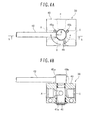
- Fig. 4A is a plan view illustrating a configuration of a directional control valve.
- Fig. 4B is a cross-sectional view taken along line S-S in Fig. 4A .
- the hydraulic drive system includes a plurality of (only one is illustrated in Fig. 3 ) main hydraulic pumps 32 and pilot pumps 28 driven by an engine 31; a hydraulic pilot type attachment-drive control valve 33; and a hydraulic pilot type operating device 34.
- the attachment-drive control valve 33 is adapted to control the flow of hydraulic fluid from the main hydraulic pump 32 to the crusher drive actuator 22, the breaker drive actuator 23 or the like when an attachment such as the crusher 17, the breaker 21 or the like is mounted to the front work device 6.
- the operating device 34 has the control pedal 26 which orders the crusher 17, the breaker 21 or the like to be driven.
- the hydraulic drive system includes a hydraulic pilot type arm control valve 35 adapted to control the flow of hydraulic fluid from the main hydraulic pump 32 to the arm cylinder 19.
- the hydraulic drive system includes a plurality of hydraulic pilot type control valves adapted to control the flow of hydraulic fluid from the main hydraulic pump 32 to the left and right travel motors 11, the blade cylinder, the turning motor, the swing cylinder 14, the boom cylinder 18, and the attachment-turning cylinder 20.
- the attachment-drive control valve 33, the arm control valve 35 and the like are of a center bypass type.
- the attachment-drive control valve 33 and the arm control valve 35 are connected in series to each other via a center bypass passage 36.
- the attachment-drive control valve 33 is connected to the crusher-drive actuator 22, the breaker-drive actuator 23 or the like via the attachment-drive lines 37a, 37b, and 38.
- the operating device 34 has a pair of pressure reduction valves which output an operative pilot pressure (secondary pilot pressure) P1 or P2 obtained by reducing the source pressure (primary pilot pressure) from the pilot pump 28 in response to the operation direction and amount of the control pedal 26. If the operative pilot pressure P1 from the operating device 34 is outputted to a pressure-receiving portion 33a of the attachment-drive control valve 33, the attachment-drive control valve 33 is switched to an operating position on the upper side in the figure. If the operative pilot pressure P2 from the operating device 34 is outputted to a pressure-receiving portion 33b of the attachment-drive control valve 33, the attachment-drive control valve 33 is switched to an operating position on the lower side in the figure. In this way, the crusher-drive actuator 22, the breaker-drive actuator 23 or the like is driven.
- second pilot pressure secondary pilot pressure
- a manually operated directional control valve 39 is interposed between the attachment-drive lines 37a, 37b as a major feature of the present embodiment.
- the directional control valve 39 includes a housing 40 having an actuator port A, a valve port B, a line port C, and a tank port D; a valve body 41 formed with a communication hole 41a adapted to establish mutual communication between any two of the ports A to D; and a rotating operation type manual control lever 42 connected to the valve body 40.
- the actuator port A is connected to the attachment-drive actuator 22 or 23 or the like via the attachment-drive line 37a.
- the valve port B is connected to the attachment-drive control valve 33 via the attachment-drive line 37b.
- the line port C is connected to the attachment-drive line 38 via a branch line 43.
- the tank port D is connected to a tank 44.
- the directional control valve 39 is switched to the switching position X.
- This can allow the attachment-drive control valve 33 to control the flow of hydraulic fluid from the main hydraulic pump 32 to the crusher-drive actuator 22 in response to the operation of the control pedal 26. Specifically, this can supply the hydraulic fluid from the main hydraulic pump 32 to the crusher-drive actuator 22 via one of the attachment-drive lines 37a, 37b and the attachment-drive line 38 and return the hydraulic fluid from the crusher-drive actuator 22 to the tank 44 via the other. In this way, the crusher-drive actuator 22 is driven to open and close the crusher 17.
- depressurizing work is performed by switching the directional control valve 39 to the switching position Y to return the hydraulic fluid in the actuator-drive line 37a to the tank 44.
- the depressurizing work is performed by switching the directional control valve 39 to the switching position Z to return the hydraulic fluid in the actuator-drive line 38 to the tank 44. In this way, the depressurizing work can be done stepwise.
- the directional control valve 39 is switched to the switching position Y.
- This can allow the attachment-drive control valve 33 to control the flow of hydraulic fluid from the main hydraulic pump 32 to the breaker-drive actuator 23 in response to the operation of the control pedal 26.
- hydraulic fluid is supplied from the main hydraulic pump 32 to the breaker-drive actuator 23 via the attachment-drive line 38.
- the breaker-drive actuator 23 can be driven to drive the breaker 21. If the breaker 21 is to be removed, depressurizing work is performed by switching the directional control valve 39 to the switching position Z to return the hydraulic fluid in the attachment-drive line 38 to the tank 44.
- the depressurizing work for the attachment-drive lines can be done with a simple and compact hydraulic circuit configuration.
- the directional control valve 39 can be easily incorporated in, i.e., easily applied to also an existing hydraulic shovel.
- the hydraulic drive system includes the operating device 34 having the pressure-reducing valve that outputs the operative pilot pressure P1 or P2 in accordance with the operation direction and amount of the control pedal 26.
- the operative pilot pressure P1 or P2 is outputted from the operating device 34 to the pressure-receiving portion 33a or 33b of the attachment-drive control valve 33.
- the present invention is not limited to this configuration. That is, because of having the significance in embodying the present invention, attachment-drive control valves other than mechanically-operated control valves do not depart from the technical concept of the present invention. One of such modifications may be configured as below.
- the hydraulic drive system includes an operating device having a potentiometer that outputs an electric operative signal in response to the operation direction and amount of the control pedal 26.
- An electromagnetic proportional pressure-reducing valve produces an operative pilot pressure P1 or P2 based on the electric operative signal from the operating device and the operative pilot pressure P1 or P2 is outputted to the pressure-receiving portion 33a or 33b of the attachment-drive control valve 33.
- the present embodiment described above takes as an example the hydraulic shovel embodying the present invention; however, the present invention is not limited to this. Specifically, the present invention may be applied to e.g. hydraulic cranes, bulldozers, etc. Also such a case can exhibit the same effect as above.
Landscapes
- Engineering & Computer Science (AREA)
- General Engineering & Computer Science (AREA)
- Mechanical Engineering (AREA)
- Mining & Mineral Resources (AREA)
- Civil Engineering (AREA)
- Structural Engineering (AREA)
- Chemical & Material Sciences (AREA)
- Analytical Chemistry (AREA)
- Physics & Mathematics (AREA)
- Fluid Mechanics (AREA)
- Operation Control Of Excavators (AREA)
- Component Parts Of Construction Machinery (AREA)
- Shovels (AREA)
Abstract
A manually operated directional control valve 39 is interposed between attachment-drive lines 37a and 37b to establish connection between an attachment-drive actuator 22 and an attachment-drive control valve 33. The directional control valve 39 is switched to any one of switching positions X, Y, and Z, the first switching position X allowing an actuator port A and a valve port B to communicate with each other and to block a line port C and a tank port D, the switching position Y allowing the actuator port A and the tank port D to communicate with each other and to block the valve port B and the line port C, and the switching position Z allowing the line port C and the tank port D to communicate with each other and to block the actuator port A and the valve port B. Thus, depressurizing work for the attachment-drive lines can be done with a hydraulic circuit having a simple, compact structure.
Description
- The present invention relates generally to construction machines in which an attachment such as a crusher, a breaker or the like is mounted for replacement. The invention more specifically relates to a hydraulic drive system for a construction machine suitable for depressurizing work for attachment-drive lines.
- A hydraulic shovel, one of construction machines, generally includes a lower travel structure; an upper swing structure turnably mounted on the lower travel structure; and a multiple joint type work device. The work device is installed on the upper swing structure so that it can be raised and lowered, with the work device including a boom, an arm, and a bucket. A hydraulic drive system for the hydraulic shovel includes e.g. a hydraulic pump driven by a prime mover such as an engine or the like; and a plurality of actuators (specifically, a travel motor, a turning motor, a boom cylinder, an arm cylinder, a bucket cylinder, etc.) driven by hydraulic fluid from the hydraulic pump. The hydraulic drive system further includes a plurality of hydraulic pilot type control valves adapted to control the flow of hydraulic fluid from the hydraulic pump to the plurality of actuators; operation means for outputting, to the corresponding control valves, operative pilot pressure produced in response to the operation of a control lever or pedal.
- To meet the various purposes of use, the hydraulic shovel is mountable with a crusher, a breaker, a mower, an auger or the like, i.e., an attachment as optional equipment in place of the bucket which is an attachment as standard equipment. An attachment-drive actuator is incorporated in the attachment such as the crusher, the breaker or the like. To deal with the mounting of such attachments, recent hydraulic shovels include an attachment-drive line connectable with the attachment-drive actuator and a hydraulic pilot-type attachment-purpose control valve connected to the attachment-drive actuator via the attachment-drive line to control the flow of hydraulic fluid from the hydraulic pump to the attachment-purpose hydraulic actuator (refer to
JP,Y 6-37087 - Usually, an attachment is mounted on a hydraulic shovel. For example, when, for replacement of such an attachment, a crusher is exchanged for a breaker as another attachment, a crusher-drive actuator is demounted from an attachment-drive line and a breaker-drive actuator is mounted to the attachment-drive line. In this case, if hydraulic fluid is trapped in the attachment-drive line, it spouts out of the line at the time of the demounting of the line. Even if a one-touch coupler (quick coupler) is attached to the end of the attachment-drive line in order to prevent the hydraulic fluid from scattering, the hydraulic fluid in the line makes the demounting and mounting work of the line difficult. Therefore, it is necessary to previously perform depressurizing work for returning the hydraulic fluid in the attachment-drive line to a tank. Thus, there is a problem with simplification in the configuration for achieving such depressurizing work.
- It is an object of the present invention to provide a hydraulic drive system for a construction machine that can perform depressurizing work for an attachment-drive line with a hydraulic circuit having a simple, compact structure.
- (1) To achieve the above object, the present invention proposes a hydraulic drive system for a construction machine according to
claim 1, which may in particular include: a hydraulic pump driven by a prime mover; an attachment-drive control valve adapted to control a flow of hydraulic fluid from the hydraulic pump to an attachment-drive actuator when an attachment in which to incorporate the attachment-drive actuator is mounted to the construction machine; first attachment-drive lines and a second attachment-drive line each adapted to establish connection between the attachment-drive actuator and the attachment-drive control valve; and a manually operated directional control valve interposed between the first attachment-drive lines, wherein the directional control valve has an actuator port connected to the attachment-drive actuator via the first attachment-drive line, a valve port connected to the attachment-drive control valve via the first attachment-drive line, a line port connected to the second attachment-drive line via a branch line, and a tank port connected to a tank, whereby the control valve is switched to any one of first, second, and third switching positions, the first switching position allowing the actuator port and the valve port to communicate with each other and to block the line port and the tank port, the second switching position allowing the actuator port and the tank port to communicate with each other and to block the valve port and the line port, and the third switching position allowing the line port and the tank port to communicate with each other and to block the actuator port and the valve port. - In the present invention, for example, when a crusher serving as an attachment in which to incorporate a feed oil bidirectional (double-acting type) attachment-drive actuator is mounted to the construction machine, the directional control valve is switched to the first switching position. With this, in response to the operation of operating means, the attachment-drive control valve controls the flow of the hydraulic fluid from the hydraulic pump to the attachment-drive actuator. Specifically, the attachment-drive control valve supplies the hydraulic fluid from the hydraulic pump to the attachment-drive actuator via one of the first and second attachment-drive lines and returns the hydraulic fluid from the attachment-drive actuator to the tank via the other of the first and second attachment-drive lines. This can drive the attachment-drive actuator to open and close the crusher. If the crusher is to be removed, the directional control valve is switched to the second switching position to return the hydraulic fluid in the first actuator-drive line to the tank for performing depressurizing work. In addition, the directional control valve is switched to the third switching position to return the hydraulic fluid in the second actuator-drive line to the tank for performing depressurizing work. For example, when a breaker serving as an attachment in which to incorporate a feed oil unidirectional (single-acting type) attachment-drive actuator is mounted to the construction machine, the directional control valve is switched to the second switching position. With this, in response to the operation of the operating means, the attachment-drive control valve controls the flow of hydraulic fluid from the hydraulic pump to the attachment-drive actuator. Specifically, in the state where one side of the attachment-drive actuator is allowed to communicate with the tank via the first attachment-drive line, the hydraulic fluid from the hydraulic pump is supplied to the attachment-drive actuator via the second attachment-drive line. This can drive the attachment-drive actuator to drive the breaker. If the breaker is to be removed, the directional control valve is switched to the third switching position to return the hydraulic fluid in the second attachment-drive line to the tank for performing depressurizing work. Thus, the present invention can perform the depressurizing work for the attachment-drive hydraulic lines with a hydraulic circuit having a simple, compact structure.
- (2) In the above, preferably, the directional control valve includes a rotating operation type manual control lever, fixed pins, and a removable bolt, the pins and bolt limiting an operative range in which the manual control lever turns and locating the manual control lever at an operative position associated with each of the first, second, and third switching positions.
- According to the present invention, the depressurizing work for the attachment-drive lines can be done with a hydraulic circuit having a simple, compact structure.
-
-
Fig. 1 is a lateral view illustrating a configuration of a hydraulic shovel embodying the present invention in the case where a crusher serving as an attachment of optional equipment is mounted to the hydraulic shovel. -
Fig. 2 is a partially enlarged side view of the hydraulic shovel in the case where a breaker serving as an attachment of optional equipment is mounted to the hydraulic shovel. -
Fig. 3 is a circuit diagram illustrating an essential configuration of a hydraulic drive system included in the hydraulic shovel according to an embodiment of the present invention. -
Fig. 4A is a plan view illustrating a configuration of a directional control valve according to an embodiment of the present invention. -
Fig. 4B is a cross-sectional view taken along line S-S inFig. 4A . - An embodiment of the present invention will hereinafter be described with reference to the drawings.
-
Fig. 1 is a lateral view illustrating a configuration of a small-sized hydraulic shovel embodying the present invention in the case where a crusher serving as an attachment of optional equipment is mounted to the hydraulic shovel. It is to be noted that the front side (the left inFig. 1 ), rear side (the right inFig. 1 ), left side (on the front side of the paper surface inFig. 1 ) and right side (on the back side of the paper surface inFig. 1 ) of an operator sitting on an operator's seat in an hydraulic shovel illustrated inFig. 1 are simply referred to as the front, rear, left, and right. - Referring to
Fig. 1 , the hydraulic shovel includes alower travel structure 2 provided with left andright crawlers 1; anupper swing structure 3 turnably mounted to the upper portion of thelower travel structure 2; a turning frame 4 serving as a basic lower structure of theupper swing structure 3; and aswing post 5 horizontally turnably mounted to the front portion of the turning frame 4. The hydraulic shovel further includes a multiple joint typefront work device 6 mounted to theswing post 5 so as to be vertically turnable (able to be raised and lowered); acanopy type cabin 7 installed on the left of the turning frame 4; and a plurality ofcovers 8 covering a major portion above the turning frame 4 other than thecabin 7. - The
lower travel structure 2 includes a generally H-shaped track frame 9; left andright drive wheels 10 rotatably supported close to the corresponding rear ends of the left and right sides of thetrack frame 9; left andright travel motors 11 rotating the left andright drive wheels 10, respectively; and left and right driven wheels (idlers) 12 rotatably supported close to the corresponding front ends of the left and right sides of thetrack frame 9 and rotated by the drive force of thedrive wheels 10 via thecorresponding crawlers 1. - An
earth removal blade 13 is installed on the front side of thetrack frame 9 so as to be movable up and down by a blade cylinder (not illustrated). A turning wheel (not illustrated) is installed between the central portion of thetrack frame 9 and the turning frame 4. A turning motor (not illustrated) is installed on the radially inside of the turning wheel so as to turn the turning frame 4 relative to thetrack frame 9. - The
swing post 5 is designed to be turnable horizontally relative to the turning frame 4 via a vertical pin (not illustrated). Theswing post 5 is horizontally turned by aswing cylinder 14 to thereby swing thefront work device 6 horizontally. - The
front work device 6 includes aboom 15 turnably coupled to theswing post 5; anarm 16 turnably coupled to the end of theboom 15; and acrusher 17 serving as an attachment of optional equipment turnably coupled to the end of thearm 16. Theboom 15, thearm 16, and thecrusher 17 are designed to be turned by aboom cylinder 18, anarm cylinder 19, and an attachment-turningcylinder 20, respectively. Thecrusher 17 can be replaced with a bucket not illustrated, an attachment as standard equipment, or abreaker 21 shown inFig. 2 , an attachment as optional equipment. - An oil-feed bidirectional (double-acting type) crusher-drive actuator 22 (see
Fig. 3 that will be described later) is incorporated in thecrusher 17 so as to open and close it. An oil-feed unidirectional (single-acting type) breaker-drive actuator 23 (seeFig. 3 that will be described later) is incorporated in thebreaker 21 so as to drive it. Incidentally, when the attachment such as thecrusher 17, thebreaker 21 or the like is mounted, an attachment-drive line (will be detailed later) connected to the crusher-drive actuator 22, the breaker-drive actuator 23 or the like is provided to extend along theboom 15 and thearm 16. - The
cabin 7 is provided with an operator's seat (seat) 24 on which an operator sits. Left and right travel control levers 25 operatable by not only a hand but a foot are installed in front of the operator'sseat 24 to drive the left andright travel motors 11 to allow the hydraulic shovel to travel forward and backward. An attachment-drive control pedal 26 (seeFig. 3 that will be described later) is installed on the left of the root of the lefttravel control lever 25. In addition, the attachment-drive control pedal 26 is adapted to drive the attachment-drive actuator (specifically, e.g. theactuator 22 for opening or closing the crusher, theactuator 23 for driving the breaker, or the like) to drive the attachment. A swing control pedal (not illustrated) is installed on the right of the root of the righttravel control lever 25. In addition, the swing control pedal is adapted to drive the swing cylinder to swing right and left the swing post 5 (in other words, the overall front work device 6). - A cross-operation
type control lever 27 and an erroneous operationprevention lock lever 29 are installed on the left of the operator'sseat 24. Thecontrol lever 27 is operated leftward or rightward to drive the turning motor, thereby turning theupper swing structure 3 leftward or rightward. In addition, thecontrol lever 27 is operated forward or rearward to drive thearm cylinder 19, thereby dumping or crowding thearm 16. Thelock lever 29 can block the source pressure from a pilot pump 28 (seeFig. 3 that will be described later). Another cross-operation type control lever (not illustrated) and ablade control lever 30 are installed on the right of the operator'sseat 24. This control lever is operated rightward or leftward to drive the attachment-turningcylinder 20, thereby turning the attachment downward or upward. In addition, the control lever is operated forward or rearward to drive theboom cylinder 18, thereby lowering or raising theboom 15. Theblade control lever 30 is adapted to drive the blade cylinder to move theblade 13 upward or downward. - The left and
right crawlers 1, theupper swing structure 3, theswing post 5, theblade 13, theboom 15, thearm 16, and the attachment (specifically, thecrusher 17, thebreaker 21 or the like) described above are operated by the hydraulic drive system installed in the hydraulic shovel. -
Fig. 3 is a circuit diagram illustrating an essential configuration of the hydraulic drive system included in the hydraulic shovel according to an embodiment of the present invention, the essential configuration being related to the drive of the attachment and the like.Fig. 4A is a plan view illustrating a configuration of a directional control valve.Fig. 4B is a cross-sectional view taken along line S-S inFig. 4A . - Referring to
Figs. 3 ,4A, and 4B , the hydraulic drive system includes a plurality of (only one is illustrated inFig. 3 ) mainhydraulic pumps 32 and pilot pumps 28 driven by anengine 31; a hydraulic pilot type attachment-drive control valve 33; and a hydraulic pilottype operating device 34. The attachment-drive control valve 33 is adapted to control the flow of hydraulic fluid from the mainhydraulic pump 32 to thecrusher drive actuator 22, thebreaker drive actuator 23 or the like when an attachment such as thecrusher 17, thebreaker 21 or the like is mounted to thefront work device 6. The operatingdevice 34 has thecontrol pedal 26 which orders thecrusher 17, thebreaker 21 or the like to be driven. Incidentally, as illustrated, the hydraulic drive system includes a hydraulic pilot typearm control valve 35 adapted to control the flow of hydraulic fluid from the mainhydraulic pump 32 to thearm cylinder 19. Although not illustrated, the hydraulic drive system includes a plurality of hydraulic pilot type control valves adapted to control the flow of hydraulic fluid from the mainhydraulic pump 32 to the left andright travel motors 11, the blade cylinder, the turning motor, theswing cylinder 14, theboom cylinder 18, and the attachment-turningcylinder 20. - The attachment-
drive control valve 33, thearm control valve 35 and the like are of a center bypass type. In the present embodiment, the attachment-drive control valve 33 and thearm control valve 35 are connected in series to each other via acenter bypass passage 36. The attachment-drive control valve 33 is connected to the crusher-drive actuator 22, the breaker-drive actuator 23 or the like via the attachment-drive lines - Although not fully illustrated, the operating
device 34 has a pair of pressure reduction valves which output an operative pilot pressure (secondary pilot pressure) P1 or P2 obtained by reducing the source pressure (primary pilot pressure) from thepilot pump 28 in response to the operation direction and amount of thecontrol pedal 26. If the operative pilot pressure P1 from the operatingdevice 34 is outputted to a pressure-receivingportion 33a of the attachment-drive control valve 33, the attachment-drive control valve 33 is switched to an operating position on the upper side in the figure. If the operative pilot pressure P2 from the operatingdevice 34 is outputted to a pressure-receivingportion 33b of the attachment-drive control valve 33, the attachment-drive control valve 33 is switched to an operating position on the lower side in the figure. In this way, the crusher-drive actuator 22, the breaker-drive actuator 23 or the like is driven. - A manually operated
directional control valve 39 is interposed between the attachment-drive lines directional control valve 39 includes ahousing 40 having an actuator port A, a valve port B, a line port C, and a tank port D; avalve body 41 formed with acommunication hole 41a adapted to establish mutual communication between any two of the ports A to D; and a rotating operation typemanual control lever 42 connected to thevalve body 40. The actuator port A is connected to the attachment-drive actuator drive line 37a. The valve port B is connected to the attachment-drive control valve 33 via the attachment-drive line 37b. The line port C is connected to the attachment-drive line 38 via abranch line 43. The tank port D is connected to atank 44. - The
directional control valve 39 is designed to switch to any one of switching positions X, Y, and Z in response to the rotating operation of themanual control lever 42. For example, at the operative position (operative angle θ = 0°) of themanual control lever 42 illustrated inFig. 4A , thedirectional control valve 39 is switched to the switching position X to allow the actuator port A and the valve port B to communicate with each other and to block the line port C and the tank port D. If themanual control lever 42 is operatively turned counterclockwise 90° as indicated with a solid arrow inFig. 4A (in other words, at an operative angle θ = 90°), thedirectional control valve 39 is switched to the switching position Y to allow the actuator port A and the tank port D to communicate with each other and to block the valve port B and the line port C. If themanual control lever 42 is further operatively turned counterclockwise 90° as indicated with a dotted-line arrow inFig. 4A (in other words, at an operative angle θ = 180°), thedirectional control valve 39 is switched to the switching position Z to allow the line port C and the tank port D to communicate with each other and to block the actuator port A and the valve port B. - The
housing 40 is provided with two fixedpins manual control lever 42 turns to a range between θ = 0° and 180°. In addition, thehousing 40 is provided with a removable bolt 46 (specifically, e.g. a wing bolt) to limit the operative range in which themanual control lever 42 turns to θ = 90°. In short, themanual control lever 42 can be located at the operative angle θ = 0° by the fixedpin 45a. When thebolt 46 is attached, themanual control lever 42 can be located at the operative angle θ = 90°. When thebolt 46 is removed, themanual control lever 42 can be located at the operative angle θ = 180°. Themanual control lever 42 can be located at the operative angle θ = 180° by the fixedpin 45b. - A description is next given of the function of the present embodiment.
- For example, when the
crusher 17 is mounted to thefront work device 6 of the hydraulic shovel, thedirectional control valve 39 is switched to the switching position X. This can allow the attachment-drive control valve 33 to control the flow of hydraulic fluid from the mainhydraulic pump 32 to the crusher-drive actuator 22 in response to the operation of thecontrol pedal 26. Specifically, this can supply the hydraulic fluid from the mainhydraulic pump 32 to the crusher-drive actuator 22 via one of the attachment-drive lines drive line 38 and return the hydraulic fluid from the crusher-drive actuator 22 to thetank 44 via the other. In this way, the crusher-drive actuator 22 is driven to open and close thecrusher 17. If thecrusher 17 is to be removed, depressurizing work is performed by switching thedirectional control valve 39 to the switching position Y to return the hydraulic fluid in the actuator-drive line 37a to thetank 44. The depressurizing work is performed by switching thedirectional control valve 39 to the switching position Z to return the hydraulic fluid in the actuator-drive line 38 to thetank 44. In this way, the depressurizing work can be done stepwise. - For example, when the
breaker 21 is mounted to thefront work device 6 of the hydraulic shovel, thedirectional control valve 39 is switched to the switching position Y. This can allow the attachment-drive control valve 33 to control the flow of hydraulic fluid from the mainhydraulic pump 32 to the breaker-drive actuator 23 in response to the operation of thecontrol pedal 26. Specifically, in the state where one side of the breaker-drive actuator 23 is allowed to communicate with thetank 44 via the attachment-drive line 37a, hydraulic fluid is supplied from the mainhydraulic pump 32 to the breaker-drive actuator 23 via the attachment-drive line 38. In this way, the breaker-drive actuator 23 can be driven to drive thebreaker 21. If thebreaker 21 is to be removed, depressurizing work is performed by switching thedirectional control valve 39 to the switching position Z to return the hydraulic fluid in the attachment-drive line 38 to thetank 44. - In the present embodiment described above, the depressurizing work for the attachment-drive lines can be done with a simple and compact hydraulic circuit configuration. In addition, the
directional control valve 39 can be easily incorporated in, i.e., easily applied to also an existing hydraulic shovel. - Incidentally, the embodiment described above takes the following configuration as an example. The hydraulic drive system includes the operating
device 34 having the pressure-reducing valve that outputs the operative pilot pressure P1 or P2 in accordance with the operation direction and amount of thecontrol pedal 26. In addition, the operative pilot pressure P1 or P2 is outputted from the operatingdevice 34 to the pressure-receivingportion drive control valve 33. However, the present invention is not limited to this configuration. That is, because of having the significance in embodying the present invention, attachment-drive control valves other than mechanically-operated control valves do not depart from the technical concept of the present invention. One of such modifications may be configured as below. The hydraulic drive system includes an operating device having a potentiometer that outputs an electric operative signal in response to the operation direction and amount of thecontrol pedal 26. An electromagnetic proportional pressure-reducing valve produces an operative pilot pressure P1 or P2 based on the electric operative signal from the operating device and the operative pilot pressure P1 or P2 is outputted to the pressure-receivingportion drive control valve 33. - The present embodiment described above takes as an example the hydraulic shovel embodying the present invention; however, the present invention is not limited to this. Specifically, the present invention may be applied to e.g. hydraulic cranes, bulldozers, etc. Also such a case can exhibit the same effect as above.
- The above embodiments of the invention as well as the appended claims and figures show multiple characterizing features of the invention in specific combinations. The skilled person will easily be able to consider further combinations or sub-combinations of these features in order to adapt the invention as defined in the in the claims to his specific needs.
Claims (2)
- A hydraulic drive system for a construction machine, comprising:a hydraulic pump (32) driven by a prime mover (31);an attachment-drive control valve (33) adapted to control a flow of hydraulic fluid from the hydraulic pump (32) to an attachment-drive actuator (22) when an attachment (17) in which to incorporate the attachment-drive actuator (22) is mounted to the construction machine;first attachment-drive lines (37a, 37b) and a second attachment-drive line (38) each adapted to establish connection between the attachment-drive actuator (22) and the attachment-drive control valve (33); and
characterized bya manually operated directional control valve (39) interposed between the first attachment-drive lines (37a, 37b),wherein the directional control valve (39) has an actuator port (A) connected to the attachment-drive actuator (22) via the first attachment-drive line (37a), a valve port (B) connected to the attachment-drive control valve (33) via the first attachment-drive line (37b), a line port (C) connected to the second attachment-drive line (38) via a branch line (43), and a tank port (D) connected to a tank (44), whereby the control valve (39) is switched to any one of first, second, and third switching positions (X), (Y), and (Z), the first switching position (X) allowing the actuator port (A) and the valve port (B) to communicate with each other and to block the line port (C) and the tank port (D), the second switching position (Y) allowing the actuator port (A) and the tank port (D) to communicate with each other and to block the valve port (B) and the line port (C), and the third switching position (Z) allowing the line port (C) and the tank port (D) to communicate with each other and to block the actuator port (A) and the valve port (B). - The hydraulic drive system for the construction machine according to claim 1,
wherein the directional control valve (39) includes a rotating operation type manual control lever (42), fixed pins (45a, 45b) and a removable bolt (46), the fixed pins (45a, 45b) and the removable bolt (46) limiting an operative range in which the manual control lever (42) turns and locating the manual control lever (42) at an operative position associated with each of the first, second, and third switching positions.
Applications Claiming Priority (1)
| Application Number | Priority Date | Filing Date | Title |
|---|---|---|---|
| JP2010042676A JP2011179191A (en) | 2010-02-26 | 2010-02-26 | Hydraulic drive unit for construction machine |
Publications (1)
| Publication Number | Publication Date |
|---|---|
| EP2362023A1 true EP2362023A1 (en) | 2011-08-31 |
Family
ID=44169179
Family Applications (1)
| Application Number | Title | Priority Date | Filing Date |
|---|---|---|---|
| EP11151508A Withdrawn EP2362023A1 (en) | 2010-02-26 | 2011-01-20 | Hydraulic drive system for construction machine |
Country Status (2)
| Country | Link |
|---|---|
| EP (1) | EP2362023A1 (en) |
| JP (1) | JP2011179191A (en) |
Cited By (2)
| Publication number | Priority date | Publication date | Assignee | Title |
|---|---|---|---|---|
| DE102012012299A1 (en) * | 2012-04-05 | 2013-10-10 | Atlas Copco Construction Tools Gmbh | Hydraulic attachment |
| WO2022073651A1 (en) * | 2020-10-06 | 2022-04-14 | Caterpillar Work Tools B.V. | Automatic pressure release |
Families Citing this family (1)
| Publication number | Priority date | Publication date | Assignee | Title |
|---|---|---|---|---|
| JP7094679B2 (en) * | 2017-09-20 | 2022-07-04 | ヤンマーパワーテクノロジー株式会社 | Work vehicle |
Citations (5)
| Publication number | Priority date | Publication date | Assignee | Title |
|---|---|---|---|---|
| JPH0637087B2 (en) | 1989-03-23 | 1994-05-18 | 住友ゴム工業株式会社 | Raw tire receiving device |
| EP1365076A1 (en) * | 2002-05-23 | 2003-11-26 | Komatsu Ltd. | Hydraulic circuit for auxiliary working implements |
| JP2005307606A (en) * | 2004-04-22 | 2005-11-04 | Sumitomo (Shi) Construction Machinery Manufacturing Co Ltd | Hydraulic piping structure of construction machine |
| JP2007262778A (en) * | 2006-03-29 | 2007-10-11 | Kobelco Contstruction Machinery Ltd | Pipe connecting device of working machine |
| DE202009007316U1 (en) * | 2009-05-22 | 2009-08-20 | Leister, Hermann | Attachment with hydraulic working equipment for hydraulic construction machinery |
-
2010
- 2010-02-26 JP JP2010042676A patent/JP2011179191A/en active Pending
-
2011
- 2011-01-20 EP EP11151508A patent/EP2362023A1/en not_active Withdrawn
Patent Citations (5)
| Publication number | Priority date | Publication date | Assignee | Title |
|---|---|---|---|---|
| JPH0637087B2 (en) | 1989-03-23 | 1994-05-18 | 住友ゴム工業株式会社 | Raw tire receiving device |
| EP1365076A1 (en) * | 2002-05-23 | 2003-11-26 | Komatsu Ltd. | Hydraulic circuit for auxiliary working implements |
| JP2005307606A (en) * | 2004-04-22 | 2005-11-04 | Sumitomo (Shi) Construction Machinery Manufacturing Co Ltd | Hydraulic piping structure of construction machine |
| JP2007262778A (en) * | 2006-03-29 | 2007-10-11 | Kobelco Contstruction Machinery Ltd | Pipe connecting device of working machine |
| DE202009007316U1 (en) * | 2009-05-22 | 2009-08-20 | Leister, Hermann | Attachment with hydraulic working equipment for hydraulic construction machinery |
Cited By (3)
| Publication number | Priority date | Publication date | Assignee | Title |
|---|---|---|---|---|
| DE102012012299A1 (en) * | 2012-04-05 | 2013-10-10 | Atlas Copco Construction Tools Gmbh | Hydraulic attachment |
| WO2022073651A1 (en) * | 2020-10-06 | 2022-04-14 | Caterpillar Work Tools B.V. | Automatic pressure release |
| US12601149B2 (en) | 2020-10-06 | 2026-04-14 | Caterpillar Work Tools B.V. | Automatic pressure release |
Also Published As
| Publication number | Publication date |
|---|---|
| JP2011179191A (en) | 2011-09-15 |
Similar Documents
| Publication | Publication Date | Title |
|---|---|---|
| JP4724664B2 (en) | Hydraulic system for work machines | |
| EP2188456A1 (en) | Hydraulic control system for a swiveling construction machine | |
| US20150053450A1 (en) | Stator for a hydraulic work tool assembly | |
| EP2855944B1 (en) | Control valve assembly | |
| JP2017187144A (en) | Work machine | |
| KR20210136084A (en) | hydraulic machine | |
| US12516503B2 (en) | Method for controlling working machine and working machine | |
| JP4446851B2 (en) | Hydraulic drive device for work machine | |
| US11591775B2 (en) | Hydraulic circuit for construction machine, and hydraulic circuit | |
| JP2011179191A (en) | Hydraulic drive unit for construction machine | |
| JP2011099239A (en) | Working machine | |
| US20170167114A1 (en) | Hydraulic clam actuator valve block | |
| EP2189578B1 (en) | Accessory pushing implement for a convertible earthmoving machine | |
| WO2022172636A1 (en) | Hydraulic shovel drive system | |
| US7857070B2 (en) | Control system using a single proportional valve | |
| US11092171B2 (en) | Valve assembly with mechanical and electro-hydraulic control | |
| KR20070095446A (en) | Hydraulic drive | |
| US20210095443A1 (en) | Hydraulic system for working machine | |
| JP3964800B2 (en) | Hydraulic circuit of work machine | |
| EP3225753A1 (en) | Hydraulic circuit of hydraulic work vehicle | |
| JP4423149B2 (en) | Construction machinery | |
| JP2002038534A (en) | Operation change-over control circuit for a plurality of actuators retrofitted in multi-functional excavator | |
| US12129875B2 (en) | Flow path switching valve, and construction machine equipped with same | |
| JP7713398B2 (en) | Working Equipment | |
| WO2025137616A1 (en) | Remote float on planer implement |
Legal Events
| Date | Code | Title | Description |
|---|---|---|---|
| PUAI | Public reference made under article 153(3) epc to a published international application that has entered the european phase |
Free format text: ORIGINAL CODE: 0009012 |
|
| 17P | Request for examination filed |
Effective date: 20110511 |
|
| AK | Designated contracting states |
Kind code of ref document: A1 Designated state(s): AL AT BE BG CH CY CZ DE DK EE ES FI FR GB GR HR HU IE IS IT LI LT LU LV MC MK MT NL NO PL PT RO RS SE SI SK SM TR |
|
| AX | Request for extension of the european patent |
Extension state: BA ME |
|
| STAA | Information on the status of an ep patent application or granted ep patent |
Free format text: STATUS: THE APPLICATION HAS BEEN WITHDRAWN |
|
| 18W | Application withdrawn |
Effective date: 20120202 |