EP4225583B1 - Printer waste diverters - Google Patents
Printer waste diverters Download PDFInfo
- Publication number
- EP4225583B1 EP4225583B1 EP21805704.0A EP21805704A EP4225583B1 EP 4225583 B1 EP4225583 B1 EP 4225583B1 EP 21805704 A EP21805704 A EP 21805704A EP 4225583 B1 EP4225583 B1 EP 4225583B1
- Authority
- EP
- European Patent Office
- Prior art keywords
- waste
- diverter
- collection bin
- slitter
- cutter
- Prior art date
- Legal status (The legal status is an assumption and is not a legal conclusion. Google has not performed a legal analysis and makes no representation as to the accuracy of the status listed.)
- Active
Links
Images







Classifications
-
- B—PERFORMING OPERATIONS; TRANSPORTING
- B26—HAND CUTTING TOOLS; CUTTING; SEVERING
- B26D—CUTTING; DETAILS COMMON TO MACHINES FOR PERFORATING, PUNCHING, CUTTING-OUT, STAMPING-OUT OR SEVERING
- B26D5/00—Arrangements for operating and controlling machines or devices for cutting, cutting-out, stamping-out, punching, perforating, or severing by means other than cutting
- B26D5/08—Means for actuating the cutting member to effect the cut
-
- B—PERFORMING OPERATIONS; TRANSPORTING
- B26—HAND CUTTING TOOLS; CUTTING; SEVERING
- B26D—CUTTING; DETAILS COMMON TO MACHINES FOR PERFORATING, PUNCHING, CUTTING-OUT, STAMPING-OUT OR SEVERING
- B26D7/00—Details of apparatus for cutting, cutting-out, stamping-out, punching, perforating, or severing by means other than cutting
- B26D7/0006—Means for guiding the cutter
-
- B—PERFORMING OPERATIONS; TRANSPORTING
- B26—HAND CUTTING TOOLS; CUTTING; SEVERING
- B26D—CUTTING; DETAILS COMMON TO MACHINES FOR PERFORATING, PUNCHING, CUTTING-OUT, STAMPING-OUT OR SEVERING
- B26D7/00—Details of apparatus for cutting, cutting-out, stamping-out, punching, perforating, or severing by means other than cutting
- B26D7/18—Means for removing cut-out material or waste
-
- B—PERFORMING OPERATIONS; TRANSPORTING
- B41—PRINTING; LINING MACHINES; TYPEWRITERS; STAMPS
- B41J—TYPEWRITERS; SELECTIVE PRINTING MECHANISMS, i.e. MECHANISMS PRINTING OTHERWISE THAN FROM A FORME; CORRECTION OF TYPOGRAPHICAL ERRORS
- B41J11/00—Devices or arrangements of selective printing mechanisms, e.g. ink-jet printers or thermal printers, for supporting or handling copy material in sheet or web form
- B41J11/66—Applications of cutting devices
- B41J11/663—Controlling cutting, cutting resulting in special shapes of the cutting line, e.g. controlling cutting positions, e.g. for cutting in the immediate vicinity of a printed image
-
- B—PERFORMING OPERATIONS; TRANSPORTING
- B41—PRINTING; LINING MACHINES; TYPEWRITERS; STAMPS
- B41J—TYPEWRITERS; SELECTIVE PRINTING MECHANISMS, i.e. MECHANISMS PRINTING OTHERWISE THAN FROM A FORME; CORRECTION OF TYPOGRAPHICAL ERRORS
- B41J11/00—Devices or arrangements of selective printing mechanisms, e.g. ink-jet printers or thermal printers, for supporting or handling copy material in sheet or web form
- B41J11/66—Applications of cutting devices
- B41J11/68—Applications of cutting devices cutting parallel to the direction of paper feed
-
- B—PERFORMING OPERATIONS; TRANSPORTING
- B41—PRINTING; LINING MACHINES; TYPEWRITERS; STAMPS
- B41J—TYPEWRITERS; SELECTIVE PRINTING MECHANISMS, i.e. MECHANISMS PRINTING OTHERWISE THAN FROM A FORME; CORRECTION OF TYPOGRAPHICAL ERRORS
- B41J11/00—Devices or arrangements of selective printing mechanisms, e.g. ink-jet printers or thermal printers, for supporting or handling copy material in sheet or web form
- B41J11/66—Applications of cutting devices
- B41J11/70—Applications of cutting devices cutting perpendicular to the direction of paper feed
-
- B—PERFORMING OPERATIONS; TRANSPORTING
- B26—HAND CUTTING TOOLS; CUTTING; SEVERING
- B26D—CUTTING; DETAILS COMMON TO MACHINES FOR PERFORATING, PUNCHING, CUTTING-OUT, STAMPING-OUT OR SEVERING
- B26D7/00—Details of apparatus for cutting, cutting-out, stamping-out, punching, perforating, or severing by means other than cutting
- B26D2007/0012—Details, accessories or auxiliary or special operations not otherwise provided for
- B26D2007/0018—Trays, reservoirs for waste, chips or cut products
-
- B—PERFORMING OPERATIONS; TRANSPORTING
- B26—HAND CUTTING TOOLS; CUTTING; SEVERING
- B26D—CUTTING; DETAILS COMMON TO MACHINES FOR PERFORATING, PUNCHING, CUTTING-OUT, STAMPING-OUT OR SEVERING
- B26D7/00—Details of apparatus for cutting, cutting-out, stamping-out, punching, perforating, or severing by means other than cutting
- B26D2007/0012—Details, accessories or auxiliary or special operations not otherwise provided for
- B26D2007/005—Details, accessories or auxiliary or special operations not otherwise provided for cutters, e.g. guillotines, used in a label maker or printer
-
- B—PERFORMING OPERATIONS; TRANSPORTING
- B26—HAND CUTTING TOOLS; CUTTING; SEVERING
- B26D—CUTTING; DETAILS COMMON TO MACHINES FOR PERFORATING, PUNCHING, CUTTING-OUT, STAMPING-OUT OR SEVERING
- B26D7/00—Details of apparatus for cutting, cutting-out, stamping-out, punching, perforating, or severing by means other than cutting
- B26D7/18—Means for removing cut-out material or waste
- B26D2007/189—Mounting blanking, stripping and break-out tools
-
- B—PERFORMING OPERATIONS; TRANSPORTING
- B26—HAND CUTTING TOOLS; CUTTING; SEVERING
- B26D—CUTTING; DETAILS COMMON TO MACHINES FOR PERFORATING, PUNCHING, CUTTING-OUT, STAMPING-OUT OR SEVERING
- B26D9/00—Cutting apparatus combined with punching or perforating apparatus or with dissimilar cutting apparatus
-
- B—PERFORMING OPERATIONS; TRANSPORTING
- B41—PRINTING; LINING MACHINES; TYPEWRITERS; STAMPS
- B41J—TYPEWRITERS; SELECTIVE PRINTING MECHANISMS, i.e. MECHANISMS PRINTING OTHERWISE THAN FROM A FORME; CORRECTION OF TYPOGRAPHICAL ERRORS
- B41J2/00—Typewriters or selective printing mechanisms characterised by the printing or marking process for which they are designed
- B41J2/315—Typewriters or selective printing mechanisms characterised by the printing or marking process for which they are designed characterised by selective application of heat to a heat sensitive printing or impression-transfer material
- B41J2/32—Typewriters or selective printing mechanisms characterised by the printing or marking process for which they are designed characterised by selective application of heat to a heat sensitive printing or impression-transfer material using thermal heads
- B41J2/325—Typewriters or selective printing mechanisms characterised by the printing or marking process for which they are designed characterised by selective application of heat to a heat sensitive printing or impression-transfer material using thermal heads by selective transfer of ink from ink carrier, e.g. from ink ribbon or sheet
Definitions
- printers such as thermal printers can utilize slitter and cutter mechanisms to remove excess print medium. Slitters cut the print medium in the direction that is perpendicular to the print head, and cutters cut the print medium in the direction that is parallel to the print head. This provides users a wider range of print sizes without requiring numerous precut sizes of print media. Slitters, cutters, and related components are generally known in the prior art, such as those described in U.S. Pat. Nos. 8,312,798 and 7,163,287 .
- US 2005/262986 (A1 ) relates to an apparatus for directing trimmed waste away from a print path.
- the waste diverter mechanisms can be made from any flexible material such as plastic.
- the waste diverter mechanisms can be made with a curved shape to allow a pre-loaded force against a contact surface of the collection bin that has a pre-determined volume, such that the pre-loaded flexible armature can provide a sufficient force to drive waste in a desired direction.
- the slitter waste and cutter waste can be deposited into the same separate collection bin with a pre-determined volume.
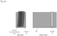
- FIG. 2A illustrates an example of inefficient stacking of waste 210 in waste collection bin 200, without the benefits of the invention described herein.
- Waste 210 may consist of slitter waste, cutter waste, or other waste such as chads from hole punches.
- waste 210 is positioned vertically in waste collection bin 200, which results in an inefficient use of space. This can result issues such as paper jams or the bin overflowing.
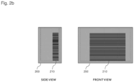
- FIG. 2B illustrates an example of efficient stacking of waste 210 in waste collection bin 200, using one or more embodiments of the invention described herein.
- Waste 210 may consist of slitter waste, cutter waste, or other waste such as chads from hole punches. In this configuration, waste 210 is positioned in a flat horizontal manner to most efficiently use the space in waste collection bin 200.
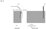
- FIG. 6 illustrates an example waste diverter 610 pre-loaded in waste collection bin 600.
- the dotted lines show the natural position of waste diverter 610 absent any force.
- waste diverter 610 can be made of a flexible material such as plastic.
- waste diverter 610 will bend and position itself such that it is touching the wall of waste collection bin 600. Therefore, when waste is deposited into waste collection bin 600 on the same wall, waste diverter 610 can direct the waste in a particular direction by moving in a particular direction. Such movement can be accomplished using drive belts such as those shown and described in relation to FIG. 3-5 . An example of this is portrayed in FIG. 7A-7D , discussed below.
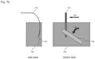
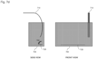
- FIG. 7A-7D illustrates the use of an example waste diverter 710 to direct waste 720 to a desirable and efficient location in waste collection bin 700.
- waste 720 can drop vertically into waste collection bin 700. As discussed above, this is inefficient and undesirable.
- waste diverter 710 can be positioned such that waste 720 will fall next to waste diverter 710, as shown in the front view of FIG. 7A . Waste diverter 710 can then move and direct waste 720 in a desired direction.
- waste diverter 710 is shown moving in direction 730 to direct waste 720 to fall in direction 740.
- FIG. 7A-7D illustrates the use of an example waste diverter 710 to direct waste 720 to a desirable and efficient location in waste collection bin 700.
- FIG. 7A after being cut from the print medium 100, waste 720 can drop vertically into waste collection bin 700. As discussed above, this is inefficient and undesirable.
- waste diverter 710 can be positioned such that waste 720 will fall next to waste diverter 710, as shown in the front
- FIG. 7C shows waste 720 after it falls to a horizontal position at the bottom of waste collection bin 700.
- waste diverter 710 moves in direction 750 back to its original position or another desired position.
- FIG. 7D shows waste 720 naturally falling via gravity in the direction 760 to a flat horizontal position at the bottom of waste collection bin 700.
- FIG. 8 illustrates an example passive waste diverter 810 in waste collection bin 800. This is as opposed to the moveable waste diverters discussed above.
- the passive waste diverter 810 is shown attached to the waste collection bin 800 using a screw 820. Note, however, that passive waste diverter 810 can be attached to waste collection bin 800 in any manner.
Landscapes
- Life Sciences & Earth Sciences (AREA)
- Forests & Forestry (AREA)
- Engineering & Computer Science (AREA)
- Mechanical Engineering (AREA)
- Details Of Cutting Devices (AREA)
- Handling Of Sheets (AREA)
- Separation, Sorting, Adjustment, Or Bending Of Sheets To Be Conveyed (AREA)
- Discharge Of Articles From Conveyors (AREA)
Description
- This application is a non-provisional of and claims priority to
U.S. provisional application number 63/087,587, filed on October 5, 2020 - While a white margin surrounding printed material is desirable in certain applications, other applications such as photographs are expected to have an image that extends to the edges of the material. To attain this goal, printers such as thermal printers can utilize slitter and cutter mechanisms to remove excess print medium. Slitters cut the print medium in the direction that is perpendicular to the print head, and cutters cut the print medium in the direction that is parallel to the print head. This provides users a wider range of print sizes without requiring numerous precut sizes of print media. Slitters, cutters, and related components are generally known in the prior art, such as those described in
U.S. Pat. Nos. 8,312,798 and7,163,287 . - The waste from slitters and cutters is generally deposited into a waste collection bin to prevent the waste from being ejected with the print medium. The depositing of waste is primarily accomplished by gravity. Slitter waste varies widely depending on the desired print size. For example, 6-inch wide print media (e.g., thermal paper) can be cut using slitters to 4-inch or 1-inch wide depending on the user's preferences. And while cutter waste is generally determined by the printer logic and remains constant regardless of the print size, cutter waste can also vary in certain applications. As such, numerous sizes of waste can be created. Relying on gravity to deposit waste into a waste collection bin often results in inconsistent and inefficient results, especially when the size of waste varies. This can result in problems and inconveniences for the user, such as paper jam conditions or the need to empty waste collection bins more often.
-
US 2005/262986 (A1 ) relates to an apparatus for directing trimmed waste away from a print path. - The inventions described herein solve the problems described above and provide apparatuses and methods to efficiently deposit waste in one or more printer waste collection bins. Specifically, waste diverter mechanisms are described to direct waste into an efficient configuration in one or more waste collection bins. This allows for a more advantageous use of waste collection bin volume and prevents issues such as paper jams. The invention is specified by the independent claim. Preferred embodiments are defined by the dependent claims.
- The waste diverter mechanisms can be made from any flexible material such as plastic. The waste diverter mechanisms can be made with a curved shape to allow a pre-loaded force against a contact surface of the collection bin that has a pre-determined volume, such that the pre-loaded flexible armature can provide a sufficient force to drive waste in a desired direction.
- In at least one embodiment, one or more waste diverter mechanisms can be used to drive the slitter waste in a direction that is parallel to the print head.
- In at least one embodiment, the slitter waste and cutter waste can be deposited into the same separate collection bin with a pre-determined volume.
- In at least one embodiment, the slitter waste and cutter waste can be deposited into separate collection bins with pre-determined volumes.
- In at least one embodiment, a threshold can be set to alert the user that one or more waste collection bins are full or at a specified capacity. This threshold can be detected using at least one or more predictive, mechanical, electrical, optical, or other means.
- In at least one embodiment, one or more waste collection bins can be connected to a mechanism to shred, compact, or otherwise decrease the volume or dispose of the waste. For example, a vacuum or chute can be employed to dispose of the waste. Shredding mechanisms known in the prior art can also be used, such as those described in
U.S. Pat. App. No. 2011/0293351 . - Various embodiments in accordance with the present disclosure will be described with reference to the drawings, in which:
-
FIG. 1A illustrates an example image printed on a portion of a print medium. -
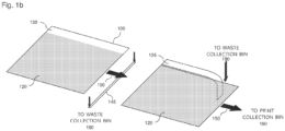
FIG. 1B illustrates an example of cutting the excess print medium. -
FIG. 2A illustrates an example of inefficient stacking of waste in a waste collection bin. -
FIG. 2B illustrates an example of efficient stacking of waste in a waste collection bin. -
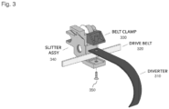
FIG. 3 illustrates an example waste diverter attached to a slitter assembly on a slitter drive belt. -
FIG. 4 illustrates an example waste diverter attached to a drive belt. -
FIG. 5 illustrates an example waste diverter attached to a cutter drive belt. -
FIG. 6 illustrates an example waste diverter in a waste collection bin, with both side and front views. -
FIG. 7A-7D illustrate the use of an example waste diverter to direct waste, with both side and front views. -
FIG. 7E illustrates an example of efficient stacking resulting from the process shown inFIG. 7A-7D , with both side and front views. -
FIG. 8 illustrates an example passive waste diverter in a waste collection bin. -
FIGs. 9A-9C illustrate the use of an example passive waste diverter to direct waste, with both side and front views. -
FIG. 9D illustrates an example of efficient stacking resulting from the process shown inFIG. 9A-9C , with both side and front views. - In the following description, various embodiments will be described. For purposes of explanation, specific configurations and details are set forth in order to provide a thorough understanding of the embodiments. However, it will also be apparent to one skilled in the art that the embodiments may be practiced without the specific details. Furthermore, well-known features may be omitted or simplified in order not to obscure the embodiment being described. The invention is defined in the claims.
- Systems and methods in accordance with various embodiments of the present disclosure may overcome one or more of the aforementioned and other deficiencies experienced in conventional approaches to collecting waste from a printer.
- Various other functions and advantages are described and suggested below as may be provided in accordance with the various embodiments.
-
FIG. 1A illustrates anexample image 120 printed on a portion ofprint medium 100 bythermal print head 110 in thereceiver transport direction 150. While a thermal print head is generally associated with a thermal printer, any suitable printer can be used in accordance with the embodiments described herein. Similarly,print medium 100 can consist of thermal paper or other media suitable for the printer used. - The
image content 120 can be printed such that it uses theentire print medium 100, or only a subset of theprint medium 100. If theentire print medium 100 is not used for printing, excess white space will be present on one or more sides of theprint medium 100. Theprint medium 100 can includeexcess receiver 130 in the "width" direction on one or both sides, which can be cut with one or more slitters inslit direction 160. For example, if theprint medium 100 is 15.2 cm (6 inches) wide and theimage content 120 is 10.2 cm (4 inches) wide, a slitter can cut the excess 5.1 cm (2 inches). Theprint medium 100 can also includeoverbleed area 140 in the "length" direction on one or both sides, which can be cut with one or more cutters incut direction 170. For example, if theprint medium 100 is 20.3 cm (8 inches) long and theimage content 120 is 16.5 cm (6.5 inches) long, a cutter can cut the excess 3.8 cm (1.5 inches). Slitters, cutters, and related components known in the prior art may be used, as described above. It should be understood that the order of components depicted inFIG. 1A and elsewhere is not the only contemplated arrangement. Other arrangements are possible and would be obvious to a person of skill based on this disclosure. -
FIG. 1B illustrates an example of cutting excess print medium fromprint medium 100. Asprint medium 100 travels in thereceiver transport direction 150,excess receiver 130 can be cut with a slitter to formslitter waste 135. Likewise,overbleed area 140 can be cut with a cutter to formcutter waste 145.Slitter waste 135 andcutter waste 145 can be deposited inwaste collection bin 190, or one or more waste collection bins. As described above, there can beexcess receiver 130 andoverbleed area 140 on both sides of theprint medium 100. Therefore, slitter waste and cutter waste can be created from both sides. After the excess print medium is cut from theprint medium 100, theimage content 120 is ejected to theprint collection bin 180. -
FIG. 2A illustrates an example of inefficient stacking ofwaste 210 inwaste collection bin 200, without the benefits of the invention described herein.Waste 210 may consist of slitter waste, cutter waste, or other waste such as chads from hole punches. In this configuration,waste 210 is positioned vertically inwaste collection bin 200, which results in an inefficient use of space. This can result issues such as paper jams or the bin overflowing. -
FIG. 2B illustrates an example of efficient stacking ofwaste 210 inwaste collection bin 200, using one or more embodiments of the invention described herein.Waste 210 may consist of slitter waste, cutter waste, or other waste such as chads from hole punches. In this configuration,waste 210 is positioned in a flat horizontal manner to most efficiently use the space inwaste collection bin 200. -
FIG. 3 illustrates anexample waste diverter 310 attached toslitter assembly 340 on aslitter drive belt 320.Waste diverter 310 is attached to slitterdrive belt 320 usingbelt clamp 330 andscrew 350. Note, however, thatwaste diverter 310 can be attached to other drive belts and may be attached in any manner. For example,waste diverter 310 can be attached to drivebelt 320 using a rivet or other fastener. In the configuration inFIG. 3 ,waste diverter 310 mirrors the slitter location due to its attachment. In this manner,waste diverter 310 can easily direct slitter waste through the movement ofslitter drive belt 320. An example of this waste direction is portrayed inFIG. 7A-7D , discussed below. -
FIG. 4 illustrates anexample waste diverter 410 attached to drivebelt 420. Thewaste diverter 410 is attached to drivebelt 420 usingbelt clamp 430,bracket 440, and screw 450. In this configuration,waste diverter 410 can be attached to a belt that is not connected to any other components, or other drive belts in the printer, such as the slitter or cutter drive belts. In this manner,waste diverter 410 can easily direct waste through the movement ofdrive belt 420. As above,waste diverter 410 can be attached to drivebelt 420 in any manner. -
FIG. 5 illustrates anexample waste diverter 510 attached tocutter drive belt 520. Thewaste diverter 510 is attached tocutter drive belt 520 usingbelt clamp 530,bracket 540, and screw 550.Cutter 570 can also be attached tocutter drive belt 520.Cutter drive belt 520 can be moved using a cutterdrive belt assembly 560. In the configuration inFIG. 5 ,waste diverter 510 has a fixed location oncutter drive belt 520 with respect tocutter 570. In this manner,waste diverter 510 can easily direct slitter or cutter waste through the movement ofcutter drive belt 520. As above,waste diverter 510 can be attached tocutter drive belt 520 in any manner. -
FIG. 6 illustrates anexample waste diverter 610 pre-loaded inwaste collection bin 600. The dotted lines show the natural position ofwaste diverter 610 absent any force. As described above,waste diverter 610 can be made of a flexible material such as plastic. Whenwaste diverter 610 is pre-loaded inwaste collection bin 600,waste diverter 610 will bend and position itself such that it is touching the wall ofwaste collection bin 600. Therefore, when waste is deposited intowaste collection bin 600 on the same wall,waste diverter 610 can direct the waste in a particular direction by moving in a particular direction. Such movement can be accomplished using drive belts such as those shown and described in relation toFIG. 3-5 . An example of this is portrayed inFIG. 7A-7D , discussed below. -
FIG. 7A-7D illustrates the use of anexample waste diverter 710 todirect waste 720 to a desirable and efficient location inwaste collection bin 700. As shown inFIG. 7A , after being cut from theprint medium 100,waste 720 can drop vertically intowaste collection bin 700. As discussed above, this is inefficient and undesirable. To alleviate this problem,waste diverter 710 can be positioned such thatwaste 720 will fall next towaste diverter 710, as shown in the front view ofFIG. 7A .Waste diverter 710 can then move anddirect waste 720 in a desired direction. InFIG. 7B ,waste diverter 710 is shown moving indirection 730 todirect waste 720 to fall in direction 740.FIG. 7C showswaste 720 after it falls to a horizontal position at the bottom ofwaste collection bin 700. After moving indirection 730,waste diverter 710 moves indirection 750 back to its original position or another desired position.FIG. 7D showswaste 720 naturally falling via gravity in the direction 760 to a flat horizontal position at the bottom ofwaste collection bin 700. -
FIG. 7E illustrates the efficient stacking ofwaste 720 resulting from the process shown inFIG. 7A-7D in accordance with one or more embodiments of the invention.Waste 720 is stacked and positioned flat in a horizontal position at the bottom ofwaste collection bin 700, providing the most efficient use of space. - In another embodiment,
FIG. 8 illustrates an examplepassive waste diverter 810 inwaste collection bin 800. This is as opposed to the moveable waste diverters discussed above. Thepassive waste diverter 810 is shown attached to thewaste collection bin 800 using a screw 820. Note, however, thatpassive waste diverter 810 can be attached towaste collection bin 800 in any manner. -
FIG. 9A-9C illustrate the use of an examplepassive waste diverter 910 todirect waste 920 to a desirable and efficient location inwaste collection bin 900. As shown inFIG. 9A , after being cut from theprint medium 100,waste 920 can drop vertically intowaste collection bin 900. As discussed above, this is inefficient and undesirable. To alleviate this problem,passive waste diverter 910 can be positioned such thatwaste 920 will fall above it, as shown in the front view ofFIG. 9A .Passive waste diverter 910 can then directwaste 920 in a desired direction. InFIG. 9B ,passive waste diverter 910 is shown directingwaste 920 to a horizontal position.FIG. 9C showswaste 920 after it naturally falls via gravity in the direction 930 to a flat horizontal position at the bottom ofwaste collection bin 900. -
FIG. 9D illustrates the efficient stacking ofwaste 920 resulting from the process shown inFIG. 9A-9C in accordance with one or more embodiments of the invention.Waste 920 is stacked and positioned flat in a horizontal position at the bottom ofwaste collection bin 900, providing the most efficient use of space.
Claims (5)
- A thermal printer, comprising:at least one slitter mechanism (340);at least one cutter mechanism (570);at least one waste collection bin (200); andat least one waste diverter (310, 510), wherein at least one waste diverter (310, 510) is substantially inside at least one waste collection bin (200).
- The thermal printer of claim 1, further comprising:
a slitter drive belt (320), wherein the slitter drive belt (320) is attached to the at least one slitter mechanism (340) and the at least one waste diverter (310). - The thermal printer of claim 1, further comprising:
a drive belt (320, 560), wherein the drive belt (320, 560) is attached to the at least one waste diverter (310). - The thermal printer of claim 1, further comprising:
a cutter drive belt (560), wherein the cutter drive belt (560) is attached to the at least one cutter mechanism (570) and the at least one waste diverter (510). - The thermal printer of claim 1, wherein the at least one waste diverter (310, 510) is made of a flexible material.
Applications Claiming Priority (2)
| Application Number | Priority Date | Filing Date | Title |
|---|---|---|---|
| US202063087587P | 2020-10-05 | 2020-10-05 | |
| PCT/US2021/053625 WO2022076453A1 (en) | 2020-10-05 | 2021-10-05 | Printer waste diverters |
Publications (2)
| Publication Number | Publication Date |
|---|---|
| EP4225583A1 EP4225583A1 (en) | 2023-08-16 |
| EP4225583B1 true EP4225583B1 (en) | 2024-07-10 |
Family
ID=78536574
Family Applications (1)
| Application Number | Title | Priority Date | Filing Date |
|---|---|---|---|
| EP21805704.0A Active EP4225583B1 (en) | 2020-10-05 | 2021-10-05 | Printer waste diverters |
Country Status (6)
| Country | Link |
|---|---|
| US (1) | US11839992B2 (en) |
| EP (1) | EP4225583B1 (en) |
| AU (1) | AU2021358754A1 (en) |
| CA (1) | CA3194455A1 (en) |
| MX (1) | MX2023004100A (en) |
| WO (1) | WO2022076453A1 (en) |
Family Cites Families (11)
| Publication number | Priority date | Publication date | Assignee | Title |
|---|---|---|---|---|
| US3312798A (en) | 1966-04-11 | 1967-04-04 | Zinsco Electrical Products | Multiple unit switch with improved interlocking contact support bar |
| JPH0564771A (en) * | 1991-04-01 | 1993-03-19 | Baba Seiki Kk | Wind pressure type weight difference sorting device in dust sorting and sorting device |
| US5139205A (en) * | 1991-07-12 | 1992-08-18 | Denis Gallagher | Segregated waste disposal system |
| JP2519608Y2 (en) * | 1992-02-12 | 1996-12-11 | コクヨ株式会社 | Sorted storage container |
| US6408750B1 (en) * | 1999-06-23 | 2002-06-25 | Fuji Photo Film Co., Ltd. | Printer capable of cutting margins |
| US6408751B1 (en) | 2000-04-26 | 2002-06-25 | Heidelberger Druckmaschinen Ag | Multi-color, multi-process automatic ink leveler |
| US7163287B2 (en) | 2004-01-21 | 2007-01-16 | Silverbrook Research Pty Ltd | Combined cutter and slitter module for a printer |
| US7395744B2 (en) * | 2004-06-01 | 2008-07-08 | Eastman Kodak Company | Chad diverting apparatus |
| JP2006088453A (en) * | 2004-09-22 | 2006-04-06 | Fuji Photo Film Co Ltd | Cutting device and method |
| US8312798B2 (en) | 2010-05-18 | 2012-11-20 | Eastman Kodak Company | Slitter with translating cutting devices |
| US20110293351A1 (en) | 2010-05-28 | 2011-12-01 | Kwarta Brian J | Print cutting system |
-
2021
- 2021-10-05 AU AU2021358754A patent/AU2021358754A1/en active Pending
- 2021-10-05 WO PCT/US2021/053625 patent/WO2022076453A1/en not_active Ceased
- 2021-10-05 EP EP21805704.0A patent/EP4225583B1/en active Active
- 2021-10-05 CA CA3194455A patent/CA3194455A1/en active Pending
- 2021-10-05 US US17/494,439 patent/US11839992B2/en active Active
- 2021-10-05 MX MX2023004100A patent/MX2023004100A/en unknown
Also Published As
| Publication number | Publication date |
|---|---|
| EP4225583A1 (en) | 2023-08-16 |
| AU2021358754A9 (en) | 2024-09-12 |
| US11839992B2 (en) | 2023-12-12 |
| US20220105654A1 (en) | 2022-04-07 |
| WO2022076453A1 (en) | 2022-04-14 |
| CA3194455A1 (en) | 2022-04-14 |
| MX2023004100A (en) | 2023-04-27 |
| AU2021358754A1 (en) | 2023-05-18 |
Similar Documents
| Publication | Publication Date | Title |
|---|---|---|
| JPH11278742A (en) | Image forming device provided with paper sheet feeding unit and paper sheet housing unit arranged in vertical direction | |
| US7036814B2 (en) | Passive media separating device | |
| US9821969B2 (en) | Paper case and paper feed system | |
| US6390397B1 (en) | Paper shredding device | |
| US20230067204A1 (en) | One Hundred Sheet Dual Throat Auto-feed Paper Shredder | |
| JP2009045921A (en) | Paper processing device | |
| US11839992B2 (en) | Printer waste diverters | |
| JP4442844B2 (en) | Sheet cutter and image forming apparatus | |
| JP2003001902A (en) | Wall mounted printer | |
| JP7016228B2 (en) | Sheet drilling device | |
| US5863038A (en) | Paper feed tray with articulating fingers to accommodate small sized papers | |
| JP2003112453A (en) | Roll paper cutting control method and recording device | |
| US7395744B2 (en) | Chad diverting apparatus | |
| JP5413582B2 (en) | Cutting device and paper discharge tray | |
| JP2004074373A (en) | Sheet cutting device and recording device | |
| JP2003232671A (en) | Punch chip quantity detecting device for punching device and punching device having this device and image forming device | |
| JP2003095512A (en) | Discharge stacker and recording apparatus provided with the discharge stacker | |
| JP2003112458A (en) | Recording device | |
| JP7214467B2 (en) | printer | |
| JP5454766B2 (en) | Cutting device | |
| JPH0790516B2 (en) | Equipment with perforation mechanism | |
| JP2010137303A (en) | Sheet processing apparatus and image forming system having the same | |
| JP2610355B2 (en) | Paper ejection guide device for printer | |
| JPH09107433A (en) | Facsimile machine | |
| CN219359618U (en) | Automatic waste recycling device of three-sided book trimming machine |
Legal Events
| Date | Code | Title | Description |
|---|---|---|---|
| STAA | Information on the status of an ep patent application or granted ep patent |
Free format text: STATUS: UNKNOWN |
|
| STAA | Information on the status of an ep patent application or granted ep patent |
Free format text: STATUS: THE INTERNATIONAL PUBLICATION HAS BEEN MADE |
|
| PUAI | Public reference made under article 153(3) epc to a published international application that has entered the european phase |
Free format text: ORIGINAL CODE: 0009012 |
|
| STAA | Information on the status of an ep patent application or granted ep patent |
Free format text: STATUS: REQUEST FOR EXAMINATION WAS MADE |
|
| 17P | Request for examination filed |
Effective date: 20230404 |
|
| AK | Designated contracting states |
Kind code of ref document: A1 Designated state(s): AL AT BE BG CH CY CZ DE DK EE ES FI FR GB GR HR HU IE IS IT LI LT LU LV MC MK MT NL NO PL PT RO RS SE SI SK SM TR |
|
| DAV | Request for validation of the european patent (deleted) | ||
| DAX | Request for extension of the european patent (deleted) | ||
| GRAP | Despatch of communication of intention to grant a patent |
Free format text: ORIGINAL CODE: EPIDOSNIGR1 |
|
| STAA | Information on the status of an ep patent application or granted ep patent |
Free format text: STATUS: GRANT OF PATENT IS INTENDED |
|
| INTG | Intention to grant announced |
Effective date: 20240220 |
|
| GRAS | Grant fee paid |
Free format text: ORIGINAL CODE: EPIDOSNIGR3 |
|
| GRAA | (expected) grant |
Free format text: ORIGINAL CODE: 0009210 |
|
| STAA | Information on the status of an ep patent application or granted ep patent |
Free format text: STATUS: THE PATENT HAS BEEN GRANTED |
|
| AK | Designated contracting states |
Kind code of ref document: B1 Designated state(s): AL AT BE BG CH CY CZ DE DK EE ES FI FR GB GR HR HU IE IS IT LI LT LU LV MC MK MT NL NO PL PT RO RS SE SI SK SM TR |
|
| P01 | Opt-out of the competence of the unified patent court (upc) registered |
Free format text: CASE NUMBER: APP_32931/2024 Effective date: 20240603 |
|
| REG | Reference to a national code |
Ref country code: CH Ref legal event code: EP |
|
| REG | Reference to a national code |
Ref country code: DE Ref legal event code: R096 Ref document number: 602021015602 Country of ref document: DE |
|
| REG | Reference to a national code |
Ref country code: NL Ref legal event code: FP |
|
| REG | Reference to a national code |
Ref country code: LT Ref legal event code: MG9D |
|
| PG25 | Lapsed in a contracting state [announced via postgrant information from national office to epo] |
Ref country code: PT Free format text: LAPSE BECAUSE OF FAILURE TO SUBMIT A TRANSLATION OF THE DESCRIPTION OR TO PAY THE FEE WITHIN THE PRESCRIBED TIME-LIMIT Effective date: 20241111 |
|
| REG | Reference to a national code |
Ref country code: AT Ref legal event code: MK05 Ref document number: 1701732 Country of ref document: AT Kind code of ref document: T Effective date: 20240710 |
|
| PG25 | Lapsed in a contracting state [announced via postgrant information from national office to epo] |
Ref country code: PT Free format text: LAPSE BECAUSE OF FAILURE TO SUBMIT A TRANSLATION OF THE DESCRIPTION OR TO PAY THE FEE WITHIN THE PRESCRIBED TIME-LIMIT Effective date: 20241111 |
|
| PG25 | Lapsed in a contracting state [announced via postgrant information from national office to epo] |
Ref country code: NO Free format text: LAPSE BECAUSE OF FAILURE TO SUBMIT A TRANSLATION OF THE DESCRIPTION OR TO PAY THE FEE WITHIN THE PRESCRIBED TIME-LIMIT Effective date: 20241010 |
|
| PG25 | Lapsed in a contracting state [announced via postgrant information from national office to epo] |
Ref country code: GR Free format text: LAPSE BECAUSE OF FAILURE TO SUBMIT A TRANSLATION OF THE DESCRIPTION OR TO PAY THE FEE WITHIN THE PRESCRIBED TIME-LIMIT Effective date: 20241011 Ref country code: FI Free format text: LAPSE BECAUSE OF FAILURE TO SUBMIT A TRANSLATION OF THE DESCRIPTION OR TO PAY THE FEE WITHIN THE PRESCRIBED TIME-LIMIT Effective date: 20240710 Ref country code: PL Free format text: LAPSE BECAUSE OF FAILURE TO SUBMIT A TRANSLATION OF THE DESCRIPTION OR TO PAY THE FEE WITHIN THE PRESCRIBED TIME-LIMIT Effective date: 20240710 |
|
| PG25 | Lapsed in a contracting state [announced via postgrant information from national office to epo] |
Ref country code: BG Free format text: LAPSE BECAUSE OF FAILURE TO SUBMIT A TRANSLATION OF THE DESCRIPTION OR TO PAY THE FEE WITHIN THE PRESCRIBED TIME-LIMIT Effective date: 20240710 |
|
| PG25 | Lapsed in a contracting state [announced via postgrant information from national office to epo] |
Ref country code: LV Free format text: LAPSE BECAUSE OF FAILURE TO SUBMIT A TRANSLATION OF THE DESCRIPTION OR TO PAY THE FEE WITHIN THE PRESCRIBED TIME-LIMIT Effective date: 20240710 |
|
| PG25 | Lapsed in a contracting state [announced via postgrant information from national office to epo] |
Ref country code: AT Free format text: LAPSE BECAUSE OF FAILURE TO SUBMIT A TRANSLATION OF THE DESCRIPTION OR TO PAY THE FEE WITHIN THE PRESCRIBED TIME-LIMIT Effective date: 20240710 Ref country code: IS Free format text: LAPSE BECAUSE OF FAILURE TO SUBMIT A TRANSLATION OF THE DESCRIPTION OR TO PAY THE FEE WITHIN THE PRESCRIBED TIME-LIMIT Effective date: 20241110 |
|
| PG25 | Lapsed in a contracting state [announced via postgrant information from national office to epo] |
Ref country code: HR Free format text: LAPSE BECAUSE OF FAILURE TO SUBMIT A TRANSLATION OF THE DESCRIPTION OR TO PAY THE FEE WITHIN THE PRESCRIBED TIME-LIMIT Effective date: 20240710 |
|
| PG25 | Lapsed in a contracting state [announced via postgrant information from national office to epo] |
Ref country code: ES Free format text: LAPSE BECAUSE OF FAILURE TO SUBMIT A TRANSLATION OF THE DESCRIPTION OR TO PAY THE FEE WITHIN THE PRESCRIBED TIME-LIMIT Effective date: 20240710 Ref country code: RS Free format text: LAPSE BECAUSE OF FAILURE TO SUBMIT A TRANSLATION OF THE DESCRIPTION OR TO PAY THE FEE WITHIN THE PRESCRIBED TIME-LIMIT Effective date: 20241010 |
|
| PG25 | Lapsed in a contracting state [announced via postgrant information from national office to epo] |
Ref country code: RS Free format text: LAPSE BECAUSE OF FAILURE TO SUBMIT A TRANSLATION OF THE DESCRIPTION OR TO PAY THE FEE WITHIN THE PRESCRIBED TIME-LIMIT Effective date: 20241010 Ref country code: PL Free format text: LAPSE BECAUSE OF FAILURE TO SUBMIT A TRANSLATION OF THE DESCRIPTION OR TO PAY THE FEE WITHIN THE PRESCRIBED TIME-LIMIT Effective date: 20240710 Ref country code: NO Free format text: LAPSE BECAUSE OF FAILURE TO SUBMIT A TRANSLATION OF THE DESCRIPTION OR TO PAY THE FEE WITHIN THE PRESCRIBED TIME-LIMIT Effective date: 20241010 Ref country code: LV Free format text: LAPSE BECAUSE OF FAILURE TO SUBMIT A TRANSLATION OF THE DESCRIPTION OR TO PAY THE FEE WITHIN THE PRESCRIBED TIME-LIMIT Effective date: 20240710 Ref country code: IS Free format text: LAPSE BECAUSE OF FAILURE TO SUBMIT A TRANSLATION OF THE DESCRIPTION OR TO PAY THE FEE WITHIN THE PRESCRIBED TIME-LIMIT Effective date: 20241110 Ref country code: HR Free format text: LAPSE BECAUSE OF FAILURE TO SUBMIT A TRANSLATION OF THE DESCRIPTION OR TO PAY THE FEE WITHIN THE PRESCRIBED TIME-LIMIT Effective date: 20240710 Ref country code: GR Free format text: LAPSE BECAUSE OF FAILURE TO SUBMIT A TRANSLATION OF THE DESCRIPTION OR TO PAY THE FEE WITHIN THE PRESCRIBED TIME-LIMIT Effective date: 20241011 Ref country code: FI Free format text: LAPSE BECAUSE OF FAILURE TO SUBMIT A TRANSLATION OF THE DESCRIPTION OR TO PAY THE FEE WITHIN THE PRESCRIBED TIME-LIMIT Effective date: 20240710 Ref country code: ES Free format text: LAPSE BECAUSE OF FAILURE TO SUBMIT A TRANSLATION OF THE DESCRIPTION OR TO PAY THE FEE WITHIN THE PRESCRIBED TIME-LIMIT Effective date: 20240710 Ref country code: BG Free format text: LAPSE BECAUSE OF FAILURE TO SUBMIT A TRANSLATION OF THE DESCRIPTION OR TO PAY THE FEE WITHIN THE PRESCRIBED TIME-LIMIT Effective date: 20240710 Ref country code: AT Free format text: LAPSE BECAUSE OF FAILURE TO SUBMIT A TRANSLATION OF THE DESCRIPTION OR TO PAY THE FEE WITHIN THE PRESCRIBED TIME-LIMIT Effective date: 20240710 |
|
| REG | Reference to a national code |
Ref country code: DE Ref legal event code: R097 Ref document number: 602021015602 Country of ref document: DE |
|
| PG25 | Lapsed in a contracting state [announced via postgrant information from national office to epo] |
Ref country code: DK Free format text: LAPSE BECAUSE OF FAILURE TO SUBMIT A TRANSLATION OF THE DESCRIPTION OR TO PAY THE FEE WITHIN THE PRESCRIBED TIME-LIMIT Effective date: 20240710 Ref country code: SM Free format text: LAPSE BECAUSE OF FAILURE TO SUBMIT A TRANSLATION OF THE DESCRIPTION OR TO PAY THE FEE WITHIN THE PRESCRIBED TIME-LIMIT Effective date: 20240710 Ref country code: RO Free format text: LAPSE BECAUSE OF FAILURE TO SUBMIT A TRANSLATION OF THE DESCRIPTION OR TO PAY THE FEE WITHIN THE PRESCRIBED TIME-LIMIT Effective date: 20240710 |
|
| PG25 | Lapsed in a contracting state [announced via postgrant information from national office to epo] |
Ref country code: EE Free format text: LAPSE BECAUSE OF FAILURE TO SUBMIT A TRANSLATION OF THE DESCRIPTION OR TO PAY THE FEE WITHIN THE PRESCRIBED TIME-LIMIT Effective date: 20240710 |
|
| PG25 | Lapsed in a contracting state [announced via postgrant information from national office to epo] |
Ref country code: CZ Free format text: LAPSE BECAUSE OF FAILURE TO SUBMIT A TRANSLATION OF THE DESCRIPTION OR TO PAY THE FEE WITHIN THE PRESCRIBED TIME-LIMIT Effective date: 20240710 |
|
| PG25 | Lapsed in a contracting state [announced via postgrant information from national office to epo] |
Ref country code: SK Free format text: LAPSE BECAUSE OF FAILURE TO SUBMIT A TRANSLATION OF THE DESCRIPTION OR TO PAY THE FEE WITHIN THE PRESCRIBED TIME-LIMIT Effective date: 20240710 Ref country code: IT Free format text: LAPSE BECAUSE OF FAILURE TO SUBMIT A TRANSLATION OF THE DESCRIPTION OR TO PAY THE FEE WITHIN THE PRESCRIBED TIME-LIMIT Effective date: 20240710 |
|
| PLBE | No opposition filed within time limit |
Free format text: ORIGINAL CODE: 0009261 |
|
| STAA | Information on the status of an ep patent application or granted ep patent |
Free format text: STATUS: NO OPPOSITION FILED WITHIN TIME LIMIT |
|
| REG | Reference to a national code |
Ref country code: CH Ref legal event code: PL |
|
| 26N | No opposition filed |
Effective date: 20250411 |
|
| PG25 | Lapsed in a contracting state [announced via postgrant information from national office to epo] |
Ref country code: MC Free format text: LAPSE BECAUSE OF FAILURE TO SUBMIT A TRANSLATION OF THE DESCRIPTION OR TO PAY THE FEE WITHIN THE PRESCRIBED TIME-LIMIT Effective date: 20240710 |
|
| PG25 | Lapsed in a contracting state [announced via postgrant information from national office to epo] |
Ref country code: BE Free format text: LAPSE BECAUSE OF NON-PAYMENT OF DUE FEES Effective date: 20241031 Ref country code: LU Free format text: LAPSE BECAUSE OF NON-PAYMENT OF DUE FEES Effective date: 20241005 |
|
| PG25 | Lapsed in a contracting state [announced via postgrant information from national office to epo] |
Ref country code: CH Free format text: LAPSE BECAUSE OF NON-PAYMENT OF DUE FEES Effective date: 20241031 |
|
| REG | Reference to a national code |
Ref country code: BE Ref legal event code: MM Effective date: 20241031 |
|
| PG25 | Lapsed in a contracting state [announced via postgrant information from national office to epo] |
Ref country code: SE Free format text: LAPSE BECAUSE OF FAILURE TO SUBMIT A TRANSLATION OF THE DESCRIPTION OR TO PAY THE FEE WITHIN THE PRESCRIBED TIME-LIMIT Effective date: 20240710 |
|
| PGFP | Annual fee paid to national office [announced via postgrant information from national office to epo] |
Ref country code: NL Payment date: 20250919 Year of fee payment: 5 |
|
| PG25 | Lapsed in a contracting state [announced via postgrant information from national office to epo] |
Ref country code: IE Free format text: LAPSE BECAUSE OF NON-PAYMENT OF DUE FEES Effective date: 20241005 |
|
| REG | Reference to a national code |
Ref country code: GB Ref legal event code: 732E Free format text: REGISTERED BETWEEN 20250925 AND 20251001 |
|
| PGFP | Annual fee paid to national office [announced via postgrant information from national office to epo] |
Ref country code: DE Payment date: 20250916 Year of fee payment: 5 |
|
| PGFP | Annual fee paid to national office [announced via postgrant information from national office to epo] |
Ref country code: GB Payment date: 20251009 Year of fee payment: 5 |
|
| PGFP | Annual fee paid to national office [announced via postgrant information from national office to epo] |
Ref country code: FR Payment date: 20251013 Year of fee payment: 5 |
|
| PG25 | Lapsed in a contracting state [announced via postgrant information from national office to epo] |
Ref country code: CY Free format text: LAPSE BECAUSE OF FAILURE TO SUBMIT A TRANSLATION OF THE DESCRIPTION OR TO PAY THE FEE WITHIN THE PRESCRIBED TIME-LIMIT; INVALID AB INITIO Effective date: 20211005 |
|
| PG25 | Lapsed in a contracting state [announced via postgrant information from national office to epo] |
Ref country code: HU Free format text: LAPSE BECAUSE OF FAILURE TO SUBMIT A TRANSLATION OF THE DESCRIPTION OR TO PAY THE FEE WITHIN THE PRESCRIBED TIME-LIMIT; INVALID AB INITIO Effective date: 20211005 |