EP4224826A1 - Folding assembly of electronic device and electronic device - Google Patents
Folding assembly of electronic device and electronic device Download PDFInfo
- Publication number
- EP4224826A1 EP4224826A1 EP22869085.5A EP22869085A EP4224826A1 EP 4224826 A1 EP4224826 A1 EP 4224826A1 EP 22869085 A EP22869085 A EP 22869085A EP 4224826 A1 EP4224826 A1 EP 4224826A1
- Authority
- EP
- European Patent Office
- Prior art keywords
- plate
- floating plate
- electronic device
- connection part
- flexible display
- Prior art date
- Legal status (The legal status is an assumption and is not a legal conclusion. Google has not performed a legal analysis and makes no representation as to the accuracy of the status listed.)
- Granted
Links
Images


Classifications
-
- H—ELECTRICITY
- H04—ELECTRIC COMMUNICATION TECHNIQUE
- H04M—TELEPHONIC COMMUNICATION
- H04M1/00—Substation equipment, e.g. for use by subscribers
- H04M1/02—Constructional features of telephone sets
- H04M1/0202—Portable telephone sets, e.g. cordless phones, mobile phones or bar type handsets
- H04M1/0206—Portable telephones comprising a plurality of mechanically joined movable body parts, e.g. hinged housings
- H04M1/0208—Portable telephones comprising a plurality of mechanically joined movable body parts, e.g. hinged housings characterized by the relative motions of the body parts
- H04M1/0214—Foldable telephones, i.e. with body parts pivoting to an open position around an axis parallel to the plane they define in closed position
- H04M1/0216—Foldable in one direction, i.e. using a one degree of freedom hinge
- H04M1/022—The hinge comprising two parallel pivoting axes
-
- G—PHYSICS
- G09—EDUCATION; CRYPTOGRAPHY; DISPLAY; ADVERTISING; SEALS
- G09F—DISPLAYING; ADVERTISING; SIGNS; LABELS OR NAME-PLATES; SEALS
- G09F9/00—Indicating arrangements for variable information in which the information is built-up on a support by selection or combination of individual elements
- G09F9/30—Indicating arrangements for variable information in which the information is built-up on a support by selection or combination of individual elements in which the desired character or characters are formed by combining individual elements
- G09F9/301—Indicating arrangements for variable information in which the information is built-up on a support by selection or combination of individual elements in which the desired character or characters are formed by combining individual elements flexible foldable or roll-able electronic displays, e.g. thin LCD, OLED
-
- G—PHYSICS
- G06—COMPUTING OR CALCULATING; COUNTING
- G06F—ELECTRIC DIGITAL DATA PROCESSING
- G06F1/00—Details not covered by groups G06F3/00 - G06F13/00 and G06F21/00
- G06F1/16—Constructional details or arrangements
- G06F1/1613—Constructional details or arrangements for portable computers
- G06F1/1633—Constructional details or arrangements of portable computers not specific to the type of enclosures covered by groups G06F1/1615 - G06F1/1626
- G06F1/1675—Miscellaneous details related to the relative movement between the different enclosures or enclosure parts
- G06F1/1681—Details related solely to hinges
-
- F—MECHANICAL ENGINEERING; LIGHTING; HEATING; WEAPONS; BLASTING
- F16—ENGINEERING ELEMENTS AND UNITS; GENERAL MEASURES FOR PRODUCING AND MAINTAINING EFFECTIVE FUNCTIONING OF MACHINES OR INSTALLATIONS; THERMAL INSULATION IN GENERAL
- F16C—SHAFTS; FLEXIBLE SHAFTS; ELEMENTS OR CRANKSHAFT MECHANISMS; ROTARY BODIES OTHER THAN GEARING ELEMENTS; BEARINGS
- F16C11/00—Pivots; Pivotal connections
- F16C11/04—Pivotal connections
-
- G—PHYSICS
- G06—COMPUTING OR CALCULATING; COUNTING
- G06F—ELECTRIC DIGITAL DATA PROCESSING
- G06F1/00—Details not covered by groups G06F3/00 - G06F13/00 and G06F21/00
- G06F1/16—Constructional details or arrangements
- G06F1/1613—Constructional details or arrangements for portable computers
- G06F1/1615—Constructional details or arrangements for portable computers with several enclosures having relative motions, each enclosure supporting at least one I/O or computing function
- G06F1/1616—Constructional details or arrangements for portable computers with several enclosures having relative motions, each enclosure supporting at least one I/O or computing function with folding flat displays, e.g. laptop computers or notebooks having a clamshell configuration, with body parts pivoting to an open position around an axis parallel to the plane they define in closed position
-
- G—PHYSICS
- G06—COMPUTING OR CALCULATING; COUNTING
- G06F—ELECTRIC DIGITAL DATA PROCESSING
- G06F1/00—Details not covered by groups G06F3/00 - G06F13/00 and G06F21/00
- G06F1/16—Constructional details or arrangements
- G06F1/1613—Constructional details or arrangements for portable computers
- G06F1/1633—Constructional details or arrangements of portable computers not specific to the type of enclosures covered by groups G06F1/1615 - G06F1/1626
- G06F1/1637—Details related to the display arrangement, including those related to the mounting of the display in the housing
- G06F1/1652—Details related to the display arrangement, including those related to the mounting of the display in the housing the display being flexible, e.g. mimicking a sheet of paper, or rollable
-
- H—ELECTRICITY
- H04—ELECTRIC COMMUNICATION TECHNIQUE
- H04M—TELEPHONIC COMMUNICATION
- H04M1/00—Substation equipment, e.g. for use by subscribers
- H04M1/02—Constructional features of telephone sets
- H04M1/0202—Portable telephone sets, e.g. cordless phones, mobile phones or bar type handsets
- H04M1/026—Details of the structure or mounting of specific components
- H04M1/0266—Details of the structure or mounting of specific components for a display module assembly
- H04M1/0268—Details of the structure or mounting of specific components for a display module assembly including a flexible display panel
Definitions
- This application relates to the field of electronic product technologies, and in particular, to a foldable assembly of an electronic device and an electronic device.
- a flexible display that is, a flexible display screen
- the flexible display and a foldable assembly are generally combined to implement folding and unfolding of the flexible display by using the foldable assembly, so as to form a folding screen of the electronic device.
- the foldable assembly includes a rotating shaft part, a floating plate, and two door plates respectively disposed on two sides of the floating plate.
- the floating plate is disposed above the rotating shaft part, and the two door plates are pivotally connected to the rotating shaft part.
- the two door plates are respectively connected to the flexible display, and drive the flexible display to fold and unfold.
- the floating plate can provide support for the flexible display from a middle position.
- the floating plate can float up and down relative to the rotating shaft part, and a groove structure is correspondingly disposed above the rotating shaft part.
- the floating plate floats downward until the floating plate is at least partially located in the groove structure, so as to reduce an overall size after folding.
- a support plate is further disposed between the door plate and the floating plate.
- One side of the support plate is fastened to the door plate; and the other side is located on an upper end face of the floating plate, and may slide on the upper end face of the floating plate.
- the support plate is bent, and the floating plate floats downward.
- a side of the support plate facing the floating plate is easy to slide along the floating plate to a gap between the floating plate and the groove structure, and is stuck, to cause the flexible display not to be unfolded.
- An object of this application is to provide a foldable assembly of an electronic device and an electronic device.
- a first aspect of embodiments of this application provides a foldable assembly of an electronic device, including a rotating shaft part, a floating plate, and two door plates, where the rotating shaft part is provided with a groove structure, the floating plate is floatably disposed above the groove structure and is located between the two door plates, the door plate is configured to fix a flexible display of the electronic device, and the door plate can rotate around the rotating shaft part to fold and unfold.
- a support plate is disposed between each door plate and the floating plate, the support plate includes a first connection part and a second connection part, the first connection part is connected to the door plate, second connection parts of two support plates are disposed opposite to each other, and a protruding part and a recessed part are disposed in the second connection part.
- the protruding parts and the recessed parts of the two support plates correspondingly fit and are located on an upper end face of the floating plate.
- the floating plate In a folded state, the floating plate is at least partially located in the groove structure, the protruding part is elastically bent and abuts against the upper end face of the floating plate, and the recessed part is separated from the floating plate.
- the second connection part is disposed as a structure that includes a protruding part and a recessed part, so that an overall width of the support plate can be increased.
- the protruding part slides along the floating plate and is in a folded state. Due to a relatively long length, the protruding part is still located on the upper end face of the floating plate after bending occurs, so as to avoid separating from the floating plate, thereby avoiding sticking, ensuring that the door plate can rotate smoothly, and the floating plate can be smoothly lifted and lowered, to ensure that the flexible display can be smoothly folded and unfolded.
- an embodiment of this application further provides a first implementation of the first aspect.
- the two support plates have a same structure. In this way, only a support plate with s same structure needs to be produced, thereby facilitating bulk production, reducing a quantity of molds, simplifying production process, and reducing costs.
- an embodiment of this application further provides a second implementation of the first aspect.
- the floating plate includes a wide segment and a narrow segment that are arranged along a length direction of the floating plate, a width of the wide segment is greater than a width of the narrow segment, a fitting segment is formed at a position where the second connection part corresponds to the narrow segment, and the fitting segment is provided with the protruding part and the recessed part.
- a protruding segment and a recessed segment are correspondingly disposed at a position where a width of the floating plate is relatively small, so that a probability that sticking occurs during a folding process can be effectively reduced.
- an embodiment of this application further provides a third implementation of the first aspect.
- the fitting segment is provided with a protruding part and a recessed part. In this way, quantities of protruding parts and recessed parts to be disposed can be reduced, and maximum sizes of the protruding part and the recessed part in limited space can be ensured, thereby ensuring structural strength of the protruding parts.
- an embodiment of this application further provides a fourth implementation of the first aspect.
- the first connection part and the door plate, the first connection part and the flexible display, and the door plate and the flexible display are all fastened through bonding. Installation process can be simplified.
- an embodiment of this application further provides a fifth implementation of the first aspect.
- Back adhesive areas are respectively disposed on end faces of two sides of the first connection part, and the first connection part is fastened to both the door plate and the flexible display by using a back adhesive layer disposed in a back adhesive area. In this way, stability of bonding between the flexible display and the door plate, between the flexible display and the support plate, and between the door plate and the support plate can be ensured, so as to avoid upwarping or bulging of a part of an edge.
- an embodiment of this application further provides a sixth implementation of the first aspect.
- the first connection part is further provided with a hollowed-out hole, and the first connection part is fastened to both the door plate and the flexible display by using an adhesive dispensing structure at the hollowed-out hole.
- the door plate, the flexible display, and the support plate are directly fastened through bonding by using the adhesive dispensing structure, so that bonding stability can be further enhanced.
- an embodiment of this application further provides a seventh implementation of the first aspect.
- the support plate is an insulating plate used to avoid impact on use of the electronic device.
- an embodiment of this application further provides an eighth implementation of the first aspect.
- the support plate is a metal plate, and a surface of the support plate is covered with an insulation layer, so as to avoid the impact on use of the electronic device.
- an embodiment of this application further provides a ninth implementation of the first aspect.
- Lubricating grease is further applied between the second connection part and the upper end face of the floating plate, so as to avoid wear between the second connection part and the floating plate, thereby protecting the second connection part and the floating plate, and prolonging a service life.
- a second aspect of embodiments of this application provides an electronic device, including a flexible display and the foldable assembly according to any one of the first aspect, the first to the ninth implementations of the first aspect.
- Embodiments of this application provide a foldable assembly of an electronic device and an electronic device, where the electronic device may be a terminal product including a foldable flexible display, such as a mobile phone, a tablet computer, a wearable device, a vehicle-mounted device, an augmented reality (augmented reality, AR)/virtual reality (virtual reality, VR) device, a notebook computer, an ultra-mobile personal computer (ultra-mobile personal computer, UMPC), a netbook, or a personal digital assistant (personal digital assistant, PDA).
- a foldable flexible display such as a mobile phone, a tablet computer, a wearable device, a vehicle-mounted device, an augmented reality (augmented reality, AR)/virtual reality (virtual reality, VR) device, a notebook computer, an ultra-mobile personal computer (ultra-mobile personal computer, UMPC), a netbook, or a personal digital assistant (personal digital assistant, PDA).
- a specific type of the electronic device is not limited in embodiments of this application.
- the electronic device includes a flexible display 200, a foldable assembly 100, and a housing 300.
- the foldable assembly 100 is approximately located in a middle position of the housing 300, and divides the housing 300 into two parts.
- the two parts may be an integrated structure, or may be a structure with two mutually independent parts that are divided by the foldable assembly 300.
- the foldable assembly 100 includes a rotating shaft part 1 and two door plates 3.
- the two door plates 3 are respectively located on two sides of the rotating shaft part 1, the door plates 3 can rotate around the rotating shaft part 1, and the two door plates 3 are respectively correspondingly connected and fastened to two parts of the housing 300.
- the housing 300 forms a structure that can rotate around the rotating shaft part 1 and implement folding and unfolding.
- the two door plates 3 can rotate around the rotating shaft part 1.
- rotation axes of the two door plates 3 are parallel or collinear, and are parallel to a length direction of the rotating shaft part 1.
- the flexible display 200 is fastened to an upper end face of the housing 300.
- a middle position of the flexible display 200 is further fastened to an upper end face of a door plate 3.
- "upper" means a side facing a user when the electronic device is in use, that is, a side that is of the flexible display 200 and that faces the user when the electronic device is in use.
- the upper end face of the door plate 3 aligns with the upper end face of the housing 300, so that the flexible display 200 can be flat in the unfolded state.
- the housing 300 may be manually operated, so that the two parts of the housing 300 are respectively bent upward in a direction indicated by a dotted arrow in FIG. 3 .
- two hands may respectively act on the two parts of the housing 300, so that the housing 300 is bent toward a side on which the flexible display 200 is disposed.
- the two parts of the housing 300 can rotate around the rotating shaft part 1 by respectively using the door plates 3, thereby implementing folding.
- the housing 300 may be manually operated, so that the two parts of the housing 300 respectively moves to two sides along a direction indicated by a dotted arrow shown in FIG. 4 .
- the two parts of the housing 300 can rotate to two sides around the rotating shaft part 1 by respectively using the door plates 3, thereby implementing unfolding.
- the foldable assembly 100 further includes a floating plate 2, and the floating plate 2 is disposed between the two door plates 3.
- a length direction of the floating plate 2, a length direction of the rotating shaft part 1, and a rotation axis of the door plate 3 are parallel to one another.
- the floating plate 2 can provide support for the flexible display 200 from a position between the two door plates 3.
- a groove structure 11 is disposed on an upper end face of the rotating shaft part 1 along the length direction of the rotating shaft part 1, and the floating plate 2 is disposed above the groove structure 11 of the rotating shaft part 1.
- the floating plate 2 can float up and down relative to the rotating shaft part 1.
- the floating plate 2 can float downward relative to the rotating shaft part 1, the flexible display 200 folds along with the door plate 3, and the middle position of the flexible display 200 floats downward along with the floating plate 2.
- the floating plate 2 is at least partially located in the groove structure 11, which may specifically be that a part of the floating plate 2 is located in the groove structure 11, or may be that all floating plate 2 enters the groove structure 11.
- a folded flexible display 200 forms a waterdrop-shaped structure between the door plate 3 and the floating plate 2 as shown in FIG. 4 .
- the floating plate 2 can provide protection for the flexible display 200 in a folded state to prevent a fracture at the middle position of the flexible display 200 due to an excessively large bending angle.
- the flexible display 200 unfolds along with the door plate 2, the floating plate 2 can float upward relative to the rotating shaft part 1, and in an unfolded state, an upper end face of the floating plate 2 and the upper end face of the door plate 3 are aligned, so that the flexible display 200 is provided with a flat support surface, and the flexible display 200 can be spread and unfolded as shown in FIG. 3 .
- the door plate 3 is provided with a main swing arm 5 and an auxiliary swing arm (not shown in the figure), and the main swing arm 5 and the auxiliary swing arm are respectively connected between the door plate 3 and the rotating shaft part 1.
- the main swing arm 5 can rotate around the rotating shaft part 1, so as to implement rotation of the door plate 3 around the rotating shaft part 1, and the auxiliary swing arm can implement a guide connection function between the door plate 3 and the rotating shaft part 1.
- the main swing arm 5 is provided with a fitting segment 51
- the rotation shaft part 1 is provided with an arc-shaped slide 12.
- the door plate 3 can drive the main swing arm 5 and the auxiliary swing arm to rotate.
- the fitting segment 51 of the main swing arm 5 can slide along the arc-shaped slide 12.
- the arc-shaped slide 12 communicates with the groove structure 11, and an end part 46 on a side of the fitting segment 51 away from the door plate 3 is further provided with a support structure 52.
- the fitting segment 51 slides along the arc-shaped slide 12 to the support structure 52 to protrude from the arc-shaped slide 12 and enter the groove structure 11.
- the support structure 52 can provide support for the floating plate 2 from a lower end face, and as the door plate 3 unfolds, the support structure 52 protrudes from the arc-shaped slide 12 and increases in height. In this case, the support structure 52 can support the floating plate 2 to float upward until the door plate 3 is in an unfolded state, the support structure 52 supports the floating plate 2 to stabilize its position, and the upper end face of the door plate 3 and the upper end face of the floating plate 2 are aligned and flat.
- the floating plate 2 may alternatively be supported by using the auxiliary swing arm.
- the auxiliary swing arm is connected to the door plate 3, and in a process in which the door plate 3 rotates around the rotating shaft part 1, the auxiliary swing arm and the lower end face of the floating plate 2 are driven to function, so that the floating plate 2 can float up and down relative to the rotating shaft part 1; alternatively, the main swing arm 5 and the auxiliary swing arm may simultaneously provide support for the floating plate 2. This is not specifically limited herein.
- a spring (not shown in the figure) is disposed in the groove structure 11, and the spring can act on the floating plate 2, so that the floating plate 2 has a tendency of moving into the groove structure 11. That is, the spring can act on the floating plate 2, so that the floating plate 2 floats downward relative to the rotating shaft part 1.
- the spring may be disposed between the lower end face of the floating plate 2 and a bottom wall of the groove structure 11.
- the door plate 3 drives the fitting segment 51 to move outward along the arc-shaped slide 12.
- the support structure 52 gradually decreases in height and enters the arc-shaped slide 12, and support action of the support structure 52 on the floating plate 2 is removed.
- the floating plate 2 floats downward under the action of the spring and enters the groove structure 11.
- floating of the floating plate 2 relative to the rotating shaft part 1 may be mechanically controlled by the support structure 52 of the main swing arm 5 and/or the auxiliary swing arm and the spring, and performance is stable, so as to ensure that in an unfolded state, the upper end face of the floating plate 2 and the upper end face of the door plate 3 can be aligned, and in a folded state, the floating plate 2 can at least partially enter the groove structure 11.
- the door plate 3 can rotate around the rotating shaft part 1.
- the floating plate 2 can float up and down relative to the rotating shaft part 1.
- a support plate 4 is disposed between each door plate 3 and the floating plate 2.
- the support plate 4 includes a first connection part 41 and a second connection part 42.
- the first connection part 41 is connected to the upper end face of the door plate 3, and second connection parts 42 of two support plates 4 are disposed opposite to each other.
- the second connection part 42 is located on the upper end face of the floating plate 2, and the support plate 4 can be configured to provide support for the flexible display 200 between the door plate 3 and the floating plate 2.
- the floating plate 2 floats upward relative to the rotating shaft part 1 to the upper end face of the floating plate 2 to align with the upper end face of the door plate 3.
- the second connection part 42 of the support plate 4 is located on the upper end face of the floating plate 2, and the support plate 4 is in a flat state, and serves as a transition connection between the door plate 3 and the floating plate 2, to ensure overall flatness of the foldable assembly 100, and provide flat support for the flexible display 200, so as to avoid a case in which the flexible display 200 may be easily damaged due to relatively weak local support.
- the floating plate 2 floats downward until the floating plate 2 is at least partially located in the groove structure 11. In this case, the floating plate 2 is located in a lowest position, and a gap between the floating plate 2 and the door plate 3 becomes larger.
- the first connection part 41 of the support plate 4 moves along with the door plate 3, and the support plate 4 is elastically bent.
- the second connection part 42 is still located on the upper end face of the floating plate 2, so as to provide transition support for the flexible display 200 between the door plate 3 and the floating plate 2.
- the floating plate 2 is at least partially located in the groove structure 11. Disposing the groove structure 11 can reduce a thickness of the foldable assembly 100 at the rotating shaft part 1, and then reduce a protrusion size of the rotating shaft part 1 after the electronic device is folded, so that when a size of a flexible display 200 is given, an overall size after the electronic device is folded can be reduced.
- the floating plate 2 can float up and down relative to the groove structure 11, there must be a gap between the floating plate 2 and the groove structure 11.
- the first connection part 41 moves along with the door plate 3, and drives two second connection parts 42 to move along the upper end face of the floating plate 2 toward an edge side of the floating plate 2.
- the support plate 4 is disposed as a structure in which the second connection part 42 is provided with a protruding part 43 and a recessed part 44, protruding parts 43 and recessed parts 44 of the two support plates 4 are disposed corresponding to each other; that is, the protruding part 43 of one support plate 4 is disposed corresponding to the recessed part 44 of the other support plate 4, and the recessed part 44 of one support plate 4 is disposed corresponding to the protruding part 43 of the other support plate 4.
- the second connection parts 42 of the two support plates 4 each are not a flat structure, but are correspondingly provided with the protruding parts 43 and the recessed parts 44. In this way, compared with a structure in which the second connection part 42 is disposed as a flat structure, an overall width of the support plate 4 can be increased. During folding, as shown in FIG. 7
- the protruding part 4 after bending occurs is still located on the upper end face of the floating plate 2 and abuts against the upper end face of the floating plate 2, to avoid separating from the floating plate 2, and avoid a case of sticking, so as to ensure that the door plate 3 can rotate smoothly and the floating plate 2 can be lifted and lowered smoothly, and then ensure that the flexible display 200 can be folded and unfolded smoothly.
- FIG. 7 a structure of the two support plates 4 is shown in FIG. 7 .
- Protruding parts 43 and recessed parts 44 of the two support plates 4 correspondingly fit, and are located on the upper end face of the floating plate 2.
- the support plate 4 is flat, and can provide flat support for the flexible display 200 between the door plate 3 and the floating plate 2.
- the support plate 4 is driven by the door plate 3 to elastically deform.
- the first connection part 41 is driven to be upwarped by the door plate 3, and the second connection part 42 floats downward along with the floating plate 2.
- the support plate 4 may be elastically bent.
- the recessed part 44 is directly driven by the first connection part 41 and separated from the floating plate 2, and the protruding part 43 is bent.
- the protruding part 43 still abuts against the upper end face of the floating plate 2 after bending occurs, and does not slide out of an edge of the floating plate 2. Therefore, it can be ensured that in a folded state, a case in which the second connection part 42 of the support plate 4 enters a gap between the floating plate 2 and the groove structure 11 to cause sticking can be avoided.
- the door plate 3 drives the flexible display 200 to unfold again, the door plate 3 drives the first connection part 41 of the support plate 4 to unfold toward two sides, the floating plate 2 also floats upward relative to the rotating shaft part 1, and the support plate 4 restores to its original state, and the protruding parts 43 and the recessed parts 44 of the two support plates 4 fit again.
- the two support plates 4 are of the same structure. Specifically, as shown in FIG. 7 , when the protruding parts 43 and the recessed parts 44 of the two support plates 4 correspondingly fit, the two support plates 4 are symmetrically disposed about a center between the two support plates.
- the first connection part 41 of one support plate 4 is connected to one door plate 3
- the other support plate 4 is reversed 180° around an axis along a length direction of the other support plates 4, and is reversed 180° around an axis along a width direction of the other support plate 4, and the first connection part 41 of the other support plate 4 is connected to the other door plate 3.
- the protruding part 43 and the recessed part 44 on two sides of a same support plate 4 are also disposed correspondingly, so that the support plate 4 can fit with the other support plate 4 with a same structure. In this way, only a support plate 4 with a same structure needs to be produced, thereby facilitating bulk production, reducing a quantity of molds, simplifying production process, and reducing costs.
- the two support plates 4 may alternatively be of different structures, provided that the protruding parts 43 and the recessed parts 44 of the two support plates 4 can correspondingly fit.
- a specific arrangement of the protruding part 43 and the recessed part 44 on the second connection part 42 is not limited.
- the protruding part 43 and the recessed part 44 may be successively arranged in a staggered manner along a length direction of the second connection part 42, or the second connection part 42 is further provided with a spacing segment 45.
- the spacing segment 45 indicates a structure in which an abutment side of the support plate 4 is not provided with the protruding part 43 or the recessed part 44, and the spacing segments 45 of the two support plates 4 are also correspondingly disposed. In an unfolded state, the protruding parts 43 and the recessed parts 44 of the two support plates 4 correspondingly fit, and the spacing segments 45 correspondingly fit and form a flat structure.
- disposing the protruding part 43 can increase an overall width of the support plate 4, so as to avoid a case in which the second connection part 42 slides into a gap between the floating plate 2 and the groove structure 11 to cause sticking.
- a specific arrangement of the protruding part 43 and the recessed part 44 is not limited.
- the protruding part 43 and the recessed part 44 may be disposed based on a specific case of the electronic device, for example, a length and a width of the floating plate 2.
- a structure of the floating plate 2 is not limited. Specifically, because of disposing of a structure of the rotating shaft part 1 and a structure of the door plate 3, a connection between the rotating shaft part 1 and the door plate 3, and the like, a width of each position of the floating plate 2 in a length direction is not consistent.
- the floating plate 2 is provided with a wide segment 21 and a narrow segment 22 in the length direction. It is easy to understand that a width of the wide segment 21 is greater than a width of the narrow segment 22. Because the width of the narrow segment 22 is relatively small, during folding, an abutment side 42 may easily slide along the narrow segment 22 to an edge to cause sticking. Therefore, the abutment side 42 is provided with a fitting segment at a position corresponding to the narrow segment 22.
- the fitting segment is provided with the protruding part 43 and the recessed part 44, so that a probability that sticking occurs during a folding process can be effectively reduced.
- a position corresponding to the abutment side 42 and the wide segment 41 is not limited in this embodiment.
- a protruding part 43 and a recessed part 44 may be disposed; or only a spacing segment 45 is disposed, but a protruding part 43 and a recessed part 44 is not disposed.
- a width of the floating plate 2 in a length direction of the floating plate 2 has not only two sizes.
- the wide segment 21 refers to a larger part of an overall width, and there is a relatively low probability that the second connection part 42 is stuck on the wide segment 21, while the narrow segment 22 refers to a smaller part of an overall width, and there is a relatively high possibility that the second connection part 42 is stuck on the wide segment 21.
- the electronic device is a mobile phone.
- a width of two ends of the floating plate 2 in a length direction is relatively small and forms the foregoing narrow segment 22, and a width in a middle part is relatively large and forms the foregoing wide segment 21. Therefore, the foregoing sticking may easily occur at positions of the two ends of the floating plate 2.
- the second connection part 42 of the support plate 4 in a length direction of the second connection part 42, includes two end parts 46 and a middle segment 47 that is located between the two end parts 46.
- the two end parts 46 are respectively corresponding to narrow segments 22 at the two ends of the floating plate 2, and the middle segment 47 is corresponding to the wide segment 21 of the floating plate 2.
- the two end parts 46 form the foregoing fitting segment and is provided with a protruding part 43 and a recessed part 44, and the middle segment 47 is provided with only a spacing segment 45 but no protruding part 43 and no recessed part 44. In this way, sticking is avoided, smoothly folding and unfolding is ensured, and an overall structure of the support plate 4 and production process are simplified
- each end part 46 is provided with one protruding part 43 and one recessed part 44.
- the quantities of the protruding part 43 and the recessed part 44 that are disposed can be reduced.
- maximum sizes of the protruding part 43 and the recessed part 44 in limited space can be ensured, and structural strength of the protruding part 43 is ensured, so that a case in which when the door plate 3 drives the flexible display 200 to fold, the protruding part 43 is bent to cause a fracture or plastic deformation, or the like can be avoided.
- a specific shape of the protruding part 43 and the recessed part 44 is not limited.
- the protruding part 43 may be set to a trapezoidal structure, or the protruding part 43 may be set to a triangular structure, a square structure, or the like, and alternatively an edge of the second connection part 42 may be set to a wave-shaped structure for a smooth transition.
- one end part 46 is provided with a protruding part 43 and a recessed part 44 from outside to inside, and the other end part 46 is provided with a recessed part 44 and a protruding part 43 from outside to inside.
- the outside refers to a side of the end part 46 away from the middle segment 47
- the inside refers to a side of the end part 46 facing the middle segment 47.
- shape structures of the protruding parts 43 disposed on the same support plate 4 may be the same or different, and the recessed part 44 may be disposed based on a corresponding protruding part 43.
- the quantities of the protruding parts 43 and the recessed parts 44 to be disposed on the second connection part 42 may be set based on a condition such as a length and a width of the floating plate 2.
- a condition such as a length and a width of the floating plate 2.
- a length of the floating plate 2 is relatively short, and a group of the protruding part 43 and the recessed part 44 may be disposed at each end part 46 of the second connection part 42.
- the electronic device is a computer display
- a length of the floating plate 2 is relatively long, two or more groups of the protruding parts 43 and the recessed parts 44 may alternatively be disposed at each end part 46 of the second connection part 42.
- first connection part 41 and the door plate 3 are fastened through bonding
- first connection part 41 and the flexible display 200 are fastened through bonding
- the door plate 3 and the flexible display 200 are also fastened through bonding.
- Process is relatively simple.
- upper and lower end faces of the first connection part 41 are respectively provided with back adhesive areas 48, and the back adhesive areas 48 of the first connection part 41 is fastened to both the door plate 3 and the flexible display 200 by using a back adhesive layer.
- the back adhesive layer is a sheet structure that basically covers the back adhesive area 48, and the door plate 3 is also fastened to the flexible display 200 by using the back adhesive layer. That is, the first connection part 41 of the support plate 4 is disposed between the door plate 3 and the flexible display 200, and the back adhesive areas 48 on the upper and lower end faces of the first connection part 41 are respectively fastened, through bonding, to the door plate 3 and the flexible display 200 by using the back adhesive layer.
- the door plate 3 can drive the flexible display 200 to fold or unfold, and can stably drive the support plate 4 to move, to enable the support plate 4 to elastically deform, to ensure a stable structure.
- the housing 300 is also fastened to the flexible display 200 by using a back adhesive layer.
- the first connection part 41 is further provided with a hollowed-out hole 49, and the first connection part 41 can be further fastened to both the door plate 3 and the flexible display 200 by using an adhesive dispensing structure at the hollowed-out hole 49. That is, when end faces at two sides of the first connection part 41 are respectively fastened to the door plate 3 and the flexible display 200 by using the back adhesive layer, the adhesive dispensing structure is further disposed at the hollowed-out hole 49.
- the adhesive dispensing structure can be filled with the hollowed-out hole 49, and the adhesive dispensing structure is fastened, through bonding, to the door plate 3 and the flexible display 200 on end faces at two sides of the hollowed-out hole 49.
- the door plate 3, the flexible display 200, and the support plate 4 are directly fastened through bonding by using the adhesive dispensing structure, thereby further enhancing bonding stability.
- a shape of the hollowed-out hole 49 is not limited. As shown in FIG. 9 , the hollowed-out hole 49 may be disposed as a strip structure disposed along a length direction of the support plate 4, or may be disposed as a circular hole structure, a polygonal structure, or the like. Sizes and shapes of hollowed-out holes 49 may be the same or may be different, which may be set based on space of the first connection part 41.
- the first connection part 41 may be provided with one row of hollowed-out holes 49 spaced along a length direction of the first connection part 41, or may be provided with two or more rows of hollowed-out holes 49.
- first connection part 41 when the first connection part 41 is provided with only one row of hollowed-out holes 49, bonding stability can be ensured, space requirements on the first connection part 41 can be reduced, and an overall structure and installation process can be simplified.
- first connection part 41 when the first connection part 41 is only provided with one row of hollowed-out holes 49, a width of the first connection part 41 disposed between the door plate 3 and the flexible display 200 can be further reduced. Therefore, when the door plate 3 rotates and drives the support plate 4 to bend, an overall bending angle of the support plate 4 can be reduced, and a service life of the support plate 4 can be prolonged.
- the support plate 4 is disposed as an insulating plate, to avoid impact on use of the electronic device.
- the support plate 4 may be directly made of an insulating material, for example, a polyethylene plate or a polyfluortetraethylene plate.
- the support plate 4 may be disposed as a metal plate.
- a surface of the metal plate is further covered with an insulation layer, so as to ensure insulativity of the support plate 4.
- the back adhesive layer can form an insulation layer in the back adhesive area 48, and the adhesive dispensing structure can form an insulation layer at the hollowed-out hole 49. Therefore, only a part other than the back adhesive area 48 of the support plate 4 needs to be covered with the insulation layer, and process is relatively simple.
- a material of the insulation layer is not limited; for example, the material may be a polyethylene film or a polytetrafluoroethylene film.
- lubricating grease is further disposed on an outer wall of the second connection part 42.
- the door plate 3 can drive the support plate 4 to bend.
- the protruding part 43 and the spacing segment 45 may be elastically bent and abut against the upper end face of the floating plate 2.
Landscapes
- Engineering & Computer Science (AREA)
- Theoretical Computer Science (AREA)
- Computer Hardware Design (AREA)
- Physics & Mathematics (AREA)
- General Engineering & Computer Science (AREA)
- General Physics & Mathematics (AREA)
- Human Computer Interaction (AREA)
- Mathematical Physics (AREA)
- Mechanical Engineering (AREA)
- Signal Processing (AREA)
- Casings For Electric Apparatus (AREA)
- Telephone Set Structure (AREA)
- Devices For Indicating Variable Information By Combining Individual Elements (AREA)
Abstract
Description
- This application claims priority to
Chinese Patent Application No. 202111112193.6, filed with the China National Intellectual Property Administration on September 18, 2021 - This application relates to the field of electronic product technologies, and in particular, to a foldable assembly of an electronic device and an electronic device.
- With development of a flexible display technology, a flexible display (that is, a flexible display screen) is increasingly applied to an electronic device. In the electronic device, the flexible display and a foldable assembly are generally combined to implement folding and unfolding of the flexible display by using the foldable assembly, so as to form a folding screen of the electronic device.
- The foldable assembly includes a rotating shaft part, a floating plate, and two door plates respectively disposed on two sides of the floating plate. The floating plate is disposed above the rotating shaft part, and the two door plates are pivotally connected to the rotating shaft part. The two door plates are respectively connected to the flexible display, and drive the flexible display to fold and unfold. The floating plate can provide support for the flexible display from a middle position.
- The floating plate can float up and down relative to the rotating shaft part, and a groove structure is correspondingly disposed above the rotating shaft part. When the two door plates rotate and drive the flexible display to fold, the floating plate floats downward until the floating plate is at least partially located in the groove structure, so as to reduce an overall size after folding.
- To ensure flatness between the door plate and the floating plate, a support plate is further disposed between the door plate and the floating plate. One side of the support plate is fastened to the door plate; and the other side is located on an upper end face of the floating plate, and may slide on the upper end face of the floating plate. However, after the door plate drives the flexible display to fold, the support plate is bent, and the floating plate floats downward. In this case, a side of the support plate facing the floating plate is easy to slide along the floating plate to a gap between the floating plate and the groove structure, and is stuck, to cause the flexible display not to be unfolded.
- Therefore, when the door plate drives the flexible display to fold, how to avoid a case in which the support plate is inserted into a gap between the floating plate and the groove structure to cause sticking, and ensure that the door plate can smoothly rotate to drive the flexible display to fold and unfold is a technical problem that needs to be resolved by a person skilled in the art.
- An object of this application is to provide a foldable assembly of an electronic device and an electronic device. When a door plate drives a flexible display to fold, a case in which a support plate is inserted into a gap between a floating plate and a groove structure to cause sticking can be avoided, thereby ensuring that the door plate can rotate smoothly to drive the flexible display to fold and unfold.
- A first aspect of embodiments of this application provides a foldable assembly of an electronic device, including a rotating shaft part, a floating plate, and two door plates, where the rotating shaft part is provided with a groove structure, the floating plate is floatably disposed above the groove structure and is located between the two door plates, the door plate is configured to fix a flexible display of the electronic device, and the door plate can rotate around the rotating shaft part to fold and unfold. A support plate is disposed between each door plate and the floating plate, the support plate includes a first connection part and a second connection part, the first connection part is connected to the door plate, second connection parts of two support plates are disposed opposite to each other, and a protruding part and a recessed part are disposed in the second connection part. In an unfolded state, the protruding parts and the recessed parts of the two support plates correspondingly fit and are located on an upper end face of the floating plate. In a folded state, the floating plate is at least partially located in the groove structure, the protruding part is elastically bent and abuts against the upper end face of the floating plate, and the recessed part is separated from the floating plate.
- The second connection part is disposed as a structure that includes a protruding part and a recessed part, so that an overall width of the support plate can be increased. During folding, the protruding part slides along the floating plate and is in a folded state. Due to a relatively long length, the protruding part is still located on the upper end face of the floating plate after bending occurs, so as to avoid separating from the floating plate, thereby avoiding sticking, ensuring that the door plate can rotate smoothly, and the floating plate can be smoothly lifted and lowered, to ensure that the flexible display can be smoothly folded and unfolded.
- Based on the first aspect, an embodiment of this application further provides a first implementation of the first aspect.
- The two support plates have a same structure. In this way, only a support plate with s same structure needs to be produced, thereby facilitating bulk production, reducing a quantity of molds, simplifying production process, and reducing costs.
- Based on the first aspect, an embodiment of this application further provides a second implementation of the first aspect.
- The floating plate includes a wide segment and a narrow segment that are arranged along a length direction of the floating plate, a width of the wide segment is greater than a width of the narrow segment, a fitting segment is formed at a position where the second connection part corresponds to the narrow segment, and the fitting segment is provided with the protruding part and the recessed part. A protruding segment and a recessed segment are correspondingly disposed at a position where a width of the floating plate is relatively small, so that a probability that sticking occurs during a folding process can be effectively reduced.
- Based on the second implementation of the first aspect, an embodiment of this application further provides a third implementation of the first aspect.
- The fitting segment is provided with a protruding part and a recessed part. In this way, quantities of protruding parts and recessed parts to be disposed can be reduced, and maximum sizes of the protruding part and the recessed part in limited space can be ensured, thereby ensuring structural strength of the protruding parts.
- Based on any one of the first aspect, or the first to the third implementations of the first aspect, an embodiment of this application further provides a fourth implementation of the first aspect.
- The first connection part and the door plate, the first connection part and the flexible display, and the door plate and the flexible display are all fastened through bonding. Installation process can be simplified.
- Based on the fourth implementation of the first aspect, an embodiment of this application further provides a fifth implementation of the first aspect.
- Back adhesive areas are respectively disposed on end faces of two sides of the first connection part, and the first connection part is fastened to both the door plate and the flexible display by using a back adhesive layer disposed in a back adhesive area. In this way, stability of bonding between the flexible display and the door plate, between the flexible display and the support plate, and between the door plate and the support plate can be ensured, so as to avoid upwarping or bulging of a part of an edge.
- Based on the fifth implementation of the first aspect, an embodiment of this application further provides a sixth implementation of the first aspect.
- The first connection part is further provided with a hollowed-out hole, and the first connection part is fastened to both the door plate and the flexible display by using an adhesive dispensing structure at the hollowed-out hole. In the hollowed-out hole, the door plate, the flexible display, and the support plate are directly fastened through bonding by using the adhesive dispensing structure, so that bonding stability can be further enhanced.
- Based on any one of the first aspect, or the first to the sixth implementations of the first aspect, an embodiment of this application further provides a seventh implementation of the first aspect.
- The support plate is an insulating plate used to avoid impact on use of the electronic device.
- Based on any one of the first aspect, or the first to the sixth implementations of the first aspect, an embodiment of this application further provides an eighth implementation of the first aspect.
- The support plate is a metal plate, and a surface of the support plate is covered with an insulation layer, so as to avoid the impact on use of the electronic device.
- Based on any one of the first aspect, or the first to the eighth implementations of the first aspect, an embodiment of this application further provides a ninth implementation of the first aspect.
- Lubricating grease is further applied between the second connection part and the upper end face of the floating plate, so as to avoid wear between the second connection part and the floating plate, thereby protecting the second connection part and the floating plate, and prolonging a service life.
- A second aspect of embodiments of this application provides an electronic device, including a flexible display and the foldable assembly according to any one of the first aspect, the first to the ninth implementations of the first aspect.
- Technical effects of the electronic device are similar to those of the foregoing foldable assembly. To save space, details are not described herein again.
- To describe technical solutions in embodiments of this application or in the conventional technology more clearly, the following briefly describes accompanying drawings required for describing embodiments or the conventional technology. Apparently, the accompanying drawings in the following description show some embodiments of the present invention, and a person of ordinary skill in the art may still derive other drawings from these accompanying drawings without creative efforts.
-
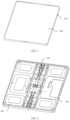
FIG. 1 is a schematic diagram of a structure of an electronic device in an unfolded state according to an embodiment of this application; -
FIG. 2 is a schematic diagram of a structure of an electronic device in an unfolded state after a screen is removed; -
FIG. 3 is a front view of an electronic device in an unfolded state, where transparent processing is performed on a housing; -
FIG. 4 is a top view of a foldable assembly in an unfolded state; -
FIG. 5 is a schematic diagram of a structure of a foldable assembly in an unfolded state after a support plate is removed; -
FIG. 6 is a sectional view ofFIG. 5 ; -
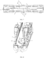
FIG. 7 is a schematic diagram of a structure of an electronic device in a folded state after a housing is removed; -
FIG. 8 is a schematic diagram of a structure of a foldable assembly in a folded state; and -
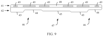
FIG. 9 is a schematic diagram of a structure of a support plate. - Reference numerals in
FIG. 1 to FIG. 9 are described as follows: - 100-Foldable assembly; 200-Flexible display; 300-Housing;
- 1-Rotating shaft part, 11-Groove structure, 12-Arc-shaped slide;
- 2-Floating plate, 21-Wide segment, 22-Narrow segment;
- 3-Door plate;
- 4-Support plate, 41-First connection part, 42-Second connection part, 43-Protruding part, 44-Recessed part, 45-Spacing segment, 46-End part, 47-Middle segment, 48-Back adhesive area, and 49-Hollowed-out hole;
- 5-Main swing arm, 51-Fitting segment, 52-Support structure.
- To enable a person skilled in the art to better understand technical solutions of this application, the following further describes this application in detail with reference to accompanying drawings and specific embodiments.
- Embodiments of this application provide a foldable assembly of an electronic device and an electronic device, where the electronic device may be a terminal product including a foldable flexible display, such as a mobile phone, a tablet computer, a wearable device, a vehicle-mounted device, an augmented reality (augmented reality, AR)/virtual reality (virtual reality, VR) device, a notebook computer, an ultra-mobile personal computer (ultra-mobile personal computer, UMPC), a netbook, or a personal digital assistant (personal digital assistant, PDA). A specific type of the electronic device is not limited in embodiments of this application.
- As shown in
FIG. 1 and FIG. 2 , the electronic device includes aflexible display 200, afoldable assembly 100, and ahousing 300. Thefoldable assembly 100 is approximately located in a middle position of thehousing 300, and divides thehousing 300 into two parts. The two parts may be an integrated structure, or may be a structure with two mutually independent parts that are divided by thefoldable assembly 300. - As shown in
FIG. 3 , thefoldable assembly 100 includes arotating shaft part 1 and twodoor plates 3. The twodoor plates 3 are respectively located on two sides of therotating shaft part 1, thedoor plates 3 can rotate around therotating shaft part 1, and the twodoor plates 3 are respectively correspondingly connected and fastened to two parts of thehousing 300. In this way, thehousing 300 forms a structure that can rotate around therotating shaft part 1 and implement folding and unfolding. In this embodiment, the twodoor plates 3 can rotate around therotating shaft part 1. Specifically, rotation axes of the twodoor plates 3 are parallel or collinear, and are parallel to a length direction of therotating shaft part 1. - The
flexible display 200 is fastened to an upper end face of thehousing 300. In addition, a middle position of theflexible display 200 is further fastened to an upper end face of adoor plate 3. As shown inFIG. 3 , "upper" means a side facing a user when the electronic device is in use, that is, a side that is of theflexible display 200 and that faces the user when the electronic device is in use. In an unfolded state, as shown inFIG. 3 , the upper end face of thedoor plate 3 aligns with the upper end face of thehousing 300, so that theflexible display 200 can be flat in the unfolded state. - Specifically, during use, if the user needs to fold the electronic device in an unfolded state, the
housing 300 may be manually operated, so that the two parts of thehousing 300 are respectively bent upward in a direction indicated by a dotted arrow inFIG. 3 . Specifically, two hands may respectively act on the two parts of thehousing 300, so that thehousing 300 is bent toward a side on which theflexible display 200 is disposed. In this case, the two parts of thehousing 300 can rotate around therotating shaft part 1 by respectively using thedoor plates 3, thereby implementing folding. Similarly, when an electronic device in a folded state needs to be unfolded, thehousing 300 may be manually operated, so that the two parts of thehousing 300 respectively moves to two sides along a direction indicated by a dotted arrow shown inFIG. 4 . In this case, the two parts of thehousing 300 can rotate to two sides around therotating shaft part 1 by respectively using thedoor plates 3, thereby implementing unfolding. - As shown in
FIG. 3 and FIG. 4 , thefoldable assembly 100 further includes a floatingplate 2, and the floatingplate 2 is disposed between the twodoor plates 3. A length direction of the floatingplate 2, a length direction of therotating shaft part 1, and a rotation axis of thedoor plate 3 are parallel to one another. The floatingplate 2 can provide support for theflexible display 200 from a position between the twodoor plates 3. Agroove structure 11 is disposed on an upper end face of therotating shaft part 1 along the length direction of therotating shaft part 1, and the floatingplate 2 is disposed above thegroove structure 11 of therotating shaft part 1. The floatingplate 2 can float up and down relative to therotating shaft part 1. Specifically, during folding, the floatingplate 2 can float downward relative to therotating shaft part 1, theflexible display 200 folds along with thedoor plate 3, and the middle position of theflexible display 200 floats downward along with the floatingplate 2. When a folded state is reached, the floatingplate 2 is at least partially located in thegroove structure 11, which may specifically be that a part of the floatingplate 2 is located in thegroove structure 11, or may be that all floatingplate 2 enters thegroove structure 11. In this case, a foldedflexible display 200 forms a waterdrop-shaped structure between thedoor plate 3 and the floatingplate 2 as shown inFIG. 4 . The floatingplate 2 can provide protection for theflexible display 200 in a folded state to prevent a fracture at the middle position of theflexible display 200 due to an excessively large bending angle. During unfolding, theflexible display 200 unfolds along with thedoor plate 2, the floatingplate 2 can float upward relative to therotating shaft part 1, and in an unfolded state, an upper end face of the floatingplate 2 and the upper end face of thedoor plate 3 are aligned, so that theflexible display 200 is provided with a flat support surface, and theflexible display 200 can be spread and unfolded as shown inFIG. 3 . - As shown in
FIG. 4 , thedoor plate 3 is provided with amain swing arm 5 and an auxiliary swing arm (not shown in the figure), and themain swing arm 5 and the auxiliary swing arm are respectively connected between thedoor plate 3 and therotating shaft part 1. Themain swing arm 5 can rotate around therotating shaft part 1, so as to implement rotation of thedoor plate 3 around therotating shaft part 1, and the auxiliary swing arm can implement a guide connection function between thedoor plate 3 and therotating shaft part 1. - As shown in
FIG. 5 and FIG. 6 , themain swing arm 5 is provided with afitting segment 51, and therotation shaft part 1 is provided with an arc-shapedslide 12. When rotating around therotating shaft part 1, thedoor plate 3 can drive themain swing arm 5 and the auxiliary swing arm to rotate. Thefitting segment 51 of themain swing arm 5 can slide along the arc-shapedslide 12. The arc-shapedslide 12 communicates with thegroove structure 11, and anend part 46 on a side of thefitting segment 51 away from thedoor plate 3 is further provided with asupport structure 52. Thefitting segment 51 slides along the arc-shapedslide 12 to thesupport structure 52 to protrude from the arc-shapedslide 12 and enter thegroove structure 11. Thesupport structure 52 can provide support for the floatingplate 2 from a lower end face, and as thedoor plate 3 unfolds, thesupport structure 52 protrudes from the arc-shapedslide 12 and increases in height. In this case, thesupport structure 52 can support the floatingplate 2 to float upward until thedoor plate 3 is in an unfolded state, thesupport structure 52 supports the floatingplate 2 to stabilize its position, and the upper end face of thedoor plate 3 and the upper end face of the floatingplate 2 are aligned and flat. - Certainly, in this embodiment, the floating
plate 2 may alternatively be supported by using the auxiliary swing arm. The auxiliary swing arm is connected to thedoor plate 3, and in a process in which thedoor plate 3 rotates around therotating shaft part 1, the auxiliary swing arm and the lower end face of the floatingplate 2 are driven to function, so that the floatingplate 2 can float up and down relative to therotating shaft part 1; alternatively, themain swing arm 5 and the auxiliary swing arm may simultaneously provide support for the floatingplate 2. This is not specifically limited herein. - In addition, a spring (not shown in the figure) is disposed in the
groove structure 11, and the spring can act on the floatingplate 2, so that the floatingplate 2 has a tendency of moving into thegroove structure 11. That is, the spring can act on the floatingplate 2, so that the floatingplate 2 floats downward relative to therotating shaft part 1. Specifically, the spring may be disposed between the lower end face of the floatingplate 2 and a bottom wall of thegroove structure 11. During folding, thedoor plate 3 drives thefitting segment 51 to move outward along the arc-shapedslide 12. In this case, thesupport structure 52 gradually decreases in height and enters the arc-shapedslide 12, and support action of thesupport structure 52 on the floatingplate 2 is removed. The floatingplate 2 floats downward under the action of the spring and enters thegroove structure 11. - That is, floating of the floating
plate 2 relative to therotating shaft part 1 may be mechanically controlled by thesupport structure 52 of themain swing arm 5 and/or the auxiliary swing arm and the spring, and performance is stable, so as to ensure that in an unfolded state, the upper end face of the floatingplate 2 and the upper end face of thedoor plate 3 can be aligned, and in a folded state, the floatingplate 2 can at least partially enter thegroove structure 11. - The
door plate 3 can rotate around therotating shaft part 1. The floatingplate 2 can float up and down relative to therotating shaft part 1. There is no direct connection between thedoor plate 3 and the floatingplate 2. Therefore, there is a gap between thedoor plate 3 and the floatingplate 2, especially in a folded state, thedoor plate 3 folds and rotates upward relative to therotating shaft part 1, and the floatingplate 2 floats downward relative to therotating shaft part 1. In this case, a gap between thedoor plate 3 and the floatingplate 2 is larger. As shown inFIG. 7 , asupport plate 4 is disposed between eachdoor plate 3 and the floatingplate 2. Thesupport plate 4 includes afirst connection part 41 and asecond connection part 42. Thefirst connection part 41 is connected to the upper end face of thedoor plate 3, andsecond connection parts 42 of twosupport plates 4 are disposed opposite to each other. Thesecond connection part 42 is located on the upper end face of the floatingplate 2, and thesupport plate 4 can be configured to provide support for theflexible display 200 between thedoor plate 3 and the floatingplate 2. - Specifically, when the
door plate 3 rotates around therotating shaft part 1 and drives theflexible display 200 to rotate to an unfolded state, the floatingplate 2 floats upward relative to therotating shaft part 1 to the upper end face of the floatingplate 2 to align with the upper end face of thedoor plate 3. In this case, thesecond connection part 42 of thesupport plate 4 is located on the upper end face of the floatingplate 2, and thesupport plate 4 is in a flat state, and serves as a transition connection between thedoor plate 3 and the floatingplate 2, to ensure overall flatness of thefoldable assembly 100, and provide flat support for theflexible display 200, so as to avoid a case in which theflexible display 200 may be easily damaged due to relatively weak local support. When thedoor plate 3 rotates around therotating shaft part 1 and drives theflexible display 200 to rotate to a folded state, the floatingplate 2 floats downward until the floatingplate 2 is at least partially located in thegroove structure 11. In this case, the floatingplate 2 is located in a lowest position, and a gap between the floatingplate 2 and thedoor plate 3 becomes larger. Thefirst connection part 41 of thesupport plate 4 moves along with thedoor plate 3, and thesupport plate 4 is elastically bent. Thesecond connection part 42 is still located on the upper end face of the floatingplate 2, so as to provide transition support for theflexible display 200 between thedoor plate 3 and the floatingplate 2. - In a folded state, the floating
plate 2 is at least partially located in thegroove structure 11. Disposing thegroove structure 11 can reduce a thickness of thefoldable assembly 100 at therotating shaft part 1, and then reduce a protrusion size of therotating shaft part 1 after the electronic device is folded, so that when a size of aflexible display 200 is given, an overall size after the electronic device is folded can be reduced. - Because the floating
plate 2 can float up and down relative to thegroove structure 11, there must be a gap between the floatingplate 2 and thegroove structure 11. During folding, thefirst connection part 41 moves along with thedoor plate 3, and drives twosecond connection parts 42 to move along the upper end face of the floatingplate 2 toward an edge side of the floatingplate 2. Because a width of the floatingplate 2 is relatively small, to avoid a case in which thesecond connection part 42 slides along the upper end face of the floatingplate 2 to outside of the floatingplate 2, and is stuck into a gap between the floatingplate 2 and thegroove structure 11, in this embodiment, thesupport plate 4 is disposed as a structure in which thesecond connection part 42 is provided with a protrudingpart 43 and a recessedpart 44, protrudingparts 43 and recessedparts 44 of the twosupport plates 4 are disposed corresponding to each other; that is, the protrudingpart 43 of onesupport plate 4 is disposed corresponding to the recessedpart 44 of theother support plate 4, and the recessedpart 44 of onesupport plate 4 is disposed corresponding to the protrudingpart 43 of theother support plate 4. As shown inFIG. 7 , thesecond connection parts 42 of the twosupport plates 4 each are not a flat structure, but are correspondingly provided with the protrudingparts 43 and the recessedparts 44. In this way, compared with a structure in which thesecond connection part 42 is disposed as a flat structure, an overall width of thesupport plate 4 can be increased. During folding, as shown inFIG. 8 , the protrudingpart 4 after bending occurs is still located on the upper end face of the floatingplate 2 and abuts against the upper end face of the floatingplate 2, to avoid separating from the floatingplate 2, and avoid a case of sticking, so as to ensure that thedoor plate 3 can rotate smoothly and the floatingplate 2 can be lifted and lowered smoothly, and then ensure that theflexible display 200 can be folded and unfolded smoothly. - Specifically, in an unfolded state, a structure of the two
support plates 4 is shown inFIG. 7 . Protrudingparts 43 and recessedparts 44 of the twosupport plates 4 correspondingly fit, and are located on the upper end face of the floatingplate 2. In this case, thesupport plate 4 is flat, and can provide flat support for theflexible display 200 between thedoor plate 3 and the floatingplate 2. When the twodoor plates 3 rotate around therotating shaft part 1 and drive theflexible display 200 to fold, thesupport plate 4 is driven by thedoor plate 3 to elastically deform. Specifically, thefirst connection part 41 is driven to be upwarped by thedoor plate 3, and thesecond connection part 42 floats downward along with the floatingplate 2. However, space in which the floatingplate 2 floats downward is limited, so that thesupport plate 4 may be elastically bent. As shown inFIG. 8 , the recessedpart 44 is directly driven by thefirst connection part 41 and separated from the floatingplate 2, and the protrudingpart 43 is bent. However, because a length of the protrudingpart 43 in a width direction of the floatingplate 2 is relatively long, the protrudingpart 43 still abuts against the upper end face of the floatingplate 2 after bending occurs, and does not slide out of an edge of the floatingplate 2. Therefore, it can be ensured that in a folded state, a case in which thesecond connection part 42 of thesupport plate 4 enters a gap between the floatingplate 2 and thegroove structure 11 to cause sticking can be avoided. When thedoor plate 3 drives theflexible display 200 to unfold again, thedoor plate 3 drives thefirst connection part 41 of thesupport plate 4 to unfold toward two sides, the floatingplate 2 also floats upward relative to therotating shaft part 1, and thesupport plate 4 restores to its original state, and the protrudingparts 43 and the recessedparts 44 of the twosupport plates 4 fit again. - In this embodiment, the two
support plates 4 are of the same structure. Specifically, as shown inFIG. 7 , when the protrudingparts 43 and the recessedparts 44 of the twosupport plates 4 correspondingly fit, the twosupport plates 4 are symmetrically disposed about a center between the two support plates. During installation, thefirst connection part 41 of onesupport plate 4 is connected to onedoor plate 3, theother support plate 4 is reversed 180° around an axis along a length direction of theother support plates 4, and is reversed 180° around an axis along a width direction of theother support plate 4, and thefirst connection part 41 of theother support plate 4 is connected to theother door plate 3. In other words, the protrudingpart 43 and the recessedpart 44 on two sides of asame support plate 4 are also disposed correspondingly, so that thesupport plate 4 can fit with theother support plate 4 with a same structure. In this way, only asupport plate 4 with a same structure needs to be produced, thereby facilitating bulk production, reducing a quantity of molds, simplifying production process, and reducing costs. Certainly, in this embodiment, the twosupport plates 4 may alternatively be of different structures, provided that the protrudingparts 43 and the recessedparts 44 of the twosupport plates 4 can correspondingly fit. - In this embodiment, a specific arrangement of the protruding
part 43 and the recessedpart 44 on thesecond connection part 42 is not limited. For example, the protrudingpart 43 and the recessedpart 44 may be successively arranged in a staggered manner along a length direction of thesecond connection part 42, or thesecond connection part 42 is further provided with aspacing segment 45. Thespacing segment 45 indicates a structure in which an abutment side of thesupport plate 4 is not provided with the protrudingpart 43 or the recessedpart 44, and thespacing segments 45 of the twosupport plates 4 are also correspondingly disposed. In an unfolded state, the protrudingparts 43 and the recessedparts 44 of the twosupport plates 4 correspondingly fit, and thespacing segments 45 correspondingly fit and form a flat structure. - Specifically, disposing the protruding
part 43 can increase an overall width of thesupport plate 4, so as to avoid a case in which thesecond connection part 42 slides into a gap between the floatingplate 2 and thegroove structure 11 to cause sticking. A specific arrangement of the protrudingpart 43 and the recessedpart 44 is not limited. The protrudingpart 43 and the recessedpart 44 may be disposed based on a specific case of the electronic device, for example, a length and a width of the floatingplate 2. - A structure of the floating
plate 2 is not limited. Specifically, because of disposing of a structure of therotating shaft part 1 and a structure of thedoor plate 3, a connection between therotating shaft part 1 and thedoor plate 3, and the like, a width of each position of the floatingplate 2 in a length direction is not consistent. Specifically, the floatingplate 2 is provided with awide segment 21 and anarrow segment 22 in the length direction. It is easy to understand that a width of thewide segment 21 is greater than a width of thenarrow segment 22. Because the width of thenarrow segment 22 is relatively small, during folding, anabutment side 42 may easily slide along thenarrow segment 22 to an edge to cause sticking. Therefore, theabutment side 42 is provided with a fitting segment at a position corresponding to thenarrow segment 22. The fitting segment is provided with the protrudingpart 43 and the recessedpart 44, so that a probability that sticking occurs during a folding process can be effectively reduced. A position corresponding to theabutment side 42 and thewide segment 41 is not limited in this embodiment. A protrudingpart 43 and a recessedpart 44 may be disposed; or only aspacing segment 45 is disposed, but a protrudingpart 43 and a recessedpart 44 is not disposed. - Specifically, the structure of the floating
plate 2 needs to be disposed based on a surrounding structure. Therefore, a width of the floatingplate 2 in a length direction of the floatingplate 2 has not only two sizes. In this embodiment, thewide segment 21 refers to a larger part of an overall width, and there is a relatively low probability that thesecond connection part 42 is stuck on thewide segment 21, while thenarrow segment 22 refers to a smaller part of an overall width, and there is a relatively high possibility that thesecond connection part 42 is stuck on thewide segment 21. - For example, the electronic device is a mobile phone. As shown in
FIG. 5 , a width of two ends of the floatingplate 2 in a length direction is relatively small and forms the foregoingnarrow segment 22, and a width in a middle part is relatively large and forms the foregoingwide segment 21. Therefore, the foregoing sticking may easily occur at positions of the two ends of the floatingplate 2. In this case, as shown inFIG. 9 , in a length direction of thesecond connection part 42, thesecond connection part 42 of thesupport plate 4 includes twoend parts 46 and amiddle segment 47 that is located between the twoend parts 46. The twoend parts 46 are respectively corresponding to narrowsegments 22 at the two ends of the floatingplate 2, and themiddle segment 47 is corresponding to thewide segment 21 of the floatingplate 2. The twoend parts 46 form the foregoing fitting segment and is provided with a protrudingpart 43 and a recessedpart 44, and themiddle segment 47 is provided with only aspacing segment 45 but no protrudingpart 43 and no recessedpart 44. In this way, sticking is avoided, smoothly folding and unfolding is ensured, and an overall structure of thesupport plate 4 and production process are simplified - Further, quantities of the protruding
parts 43 and the recessedparts 44 to be disposed on each end part 46 (that is, a fitting segment) are not limited. As shown inFIG. 9 , eachend part 46 is provided with one protrudingpart 43 and one recessedpart 44. In this way, the quantities of the protrudingpart 43 and the recessedpart 44 that are disposed can be reduced. In addition, maximum sizes of the protrudingpart 43 and the recessedpart 44 in limited space can be ensured, and structural strength of the protrudingpart 43 is ensured, so that a case in which when thedoor plate 3 drives theflexible display 200 to fold, the protrudingpart 43 is bent to cause a fracture or plastic deformation, or the like can be avoided. - In this embodiment, a specific shape of the protruding
part 43 and the recessedpart 44 is not limited. As shown inFIG. 9 , the protrudingpart 43 may be set to a trapezoidal structure, or the protrudingpart 43 may be set to a triangular structure, a square structure, or the like, and alternatively an edge of thesecond connection part 42 may be set to a wave-shaped structure for a smooth transition. - As shown in
FIG. 9 , in thesecond connection part 42 of asame support plate 4, oneend part 46 is provided with a protrudingpart 43 and a recessedpart 44 from outside to inside, and theother end part 46 is provided with a recessedpart 44 and a protrudingpart 43 from outside to inside. The outside refers to a side of theend part 46 away from themiddle segment 47, and the inside refers to a side of theend part 46 facing themiddle segment 47. In this way, twosame support plates 4 can fit with each other. In addition, in this embodiment, shape structures of the protrudingparts 43 disposed on thesame support plate 4 may be the same or different, and the recessedpart 44 may be disposed based on a corresponding protrudingpart 43. - Certainly, the quantities of the protruding
parts 43 and the recessedparts 44 to be disposed on thesecond connection part 42 may be set based on a condition such as a length and a width of the floatingplate 2. For example, when the electronic device is a mobile phone, a length of the floatingplate 2 is relatively short, and a group of the protrudingpart 43 and the recessedpart 44 may be disposed at eachend part 46 of thesecond connection part 42. When the electronic device is a computer display, a length of the floatingplate 2 is relatively long, two or more groups of the protrudingparts 43 and the recessedparts 44 may alternatively be disposed at eachend part 46 of thesecond connection part 42. - In this embodiment, the
first connection part 41 and thedoor plate 3 are fastened through bonding, thefirst connection part 41 and theflexible display 200 are fastened through bonding, and thedoor plate 3 and theflexible display 200 are also fastened through bonding. Process is relatively simple. - As shown in
FIG. 9 , upper and lower end faces of thefirst connection part 41 are respectively provided with backadhesive areas 48, and the backadhesive areas 48 of thefirst connection part 41 is fastened to both thedoor plate 3 and theflexible display 200 by using a back adhesive layer. The back adhesive layer is a sheet structure that basically covers the backadhesive area 48, and thedoor plate 3 is also fastened to theflexible display 200 by using the back adhesive layer. That is, thefirst connection part 41 of thesupport plate 4 is disposed between thedoor plate 3 and theflexible display 200, and the backadhesive areas 48 on the upper and lower end faces of thefirst connection part 41 are respectively fastened, through bonding, to thedoor plate 3 and theflexible display 200 by using the back adhesive layer. In this way, stability of bonding between theflexible display 200 and thedoor plate 3, stability of bonding between theflexible display 200 and thesupport plate 4, and stability of bonding between thedoor plate 3 and thesupport plate 4 can be ensured, so as to avoid upwarping or bulging of a part of an edge. In addition, it is ensured that in a rotation process, thedoor plate 3 can drive theflexible display 200 to fold or unfold, and can stably drive thesupport plate 4 to move, to enable thesupport plate 4 to elastically deform, to ensure a stable structure. In addition, thehousing 300 is also fastened to theflexible display 200 by using a back adhesive layer. - Further, as shown in
FIG. 9 , thefirst connection part 41 is further provided with a hollowed-out hole 49, and thefirst connection part 41 can be further fastened to both thedoor plate 3 and theflexible display 200 by using an adhesive dispensing structure at the hollowed-out hole 49. That is, when end faces at two sides of thefirst connection part 41 are respectively fastened to thedoor plate 3 and theflexible display 200 by using the back adhesive layer, the adhesive dispensing structure is further disposed at the hollowed-out hole 49. The adhesive dispensing structure can be filled with the hollowed-out hole 49, and the adhesive dispensing structure is fastened, through bonding, to thedoor plate 3 and theflexible display 200 on end faces at two sides of the hollowed-out hole 49. At the hollowed-out hole 49, thedoor plate 3, theflexible display 200, and thesupport plate 4 are directly fastened through bonding by using the adhesive dispensing structure, thereby further enhancing bonding stability. - Specifically, in this embodiment, a shape of the hollowed-
out hole 49 is not limited. As shown inFIG. 9 , the hollowed-out hole 49 may be disposed as a strip structure disposed along a length direction of thesupport plate 4, or may be disposed as a circular hole structure, a polygonal structure, or the like. Sizes and shapes of hollowed-outholes 49 may be the same or may be different, which may be set based on space of thefirst connection part 41. Thefirst connection part 41 may be provided with one row of hollowed-outholes 49 spaced along a length direction of thefirst connection part 41, or may be provided with two or more rows of hollowed-out holes 49. In this embodiment, when thefirst connection part 41 is provided with only one row of hollowed-outholes 49, bonding stability can be ensured, space requirements on thefirst connection part 41 can be reduced, and an overall structure and installation process can be simplified. In addition, when thefirst connection part 41 is only provided with one row of hollowed-outholes 49, a width of thefirst connection part 41 disposed between thedoor plate 3 and theflexible display 200 can be further reduced. Therefore, when thedoor plate 3 rotates and drives thesupport plate 4 to bend, an overall bending angle of thesupport plate 4 can be reduced, and a service life of thesupport plate 4 can be prolonged. - In this embodiment, the
support plate 4 is disposed as an insulating plate, to avoid impact on use of the electronic device. Specifically, thesupport plate 4 may be directly made of an insulating material, for example, a polyethylene plate or a polyfluortetraethylene plate. Alternatively, thesupport plate 4 may be disposed as a metal plate. In addition, a surface of the metal plate is further covered with an insulation layer, so as to ensure insulativity of thesupport plate 4. - When the
support plate 4 is a metal plate, the back adhesive layer can form an insulation layer in the backadhesive area 48, and the adhesive dispensing structure can form an insulation layer at the hollowed-out hole 49. Therefore, only a part other than the backadhesive area 48 of thesupport plate 4 needs to be covered with the insulation layer, and process is relatively simple. Specifically, in this embodiment, a material of the insulation layer is not limited; for example, the material may be a polyethylene film or a polytetrafluoroethylene film. - In addition, lubricating grease is further disposed on an outer wall of the
second connection part 42. When rotating around therotating shaft part 1, thedoor plate 3 can drive thesupport plate 4 to bend. In this process, the protrudingpart 43 and thespacing segment 45 may be elastically bent and abut against the upper end face of the floatingplate 2. In addition, there is relative sliding between the protrudingpart 43 and the upper end face of the floatingplate 2 and between the spacingsegment 45 and the upper end face of the floatingplate 2. Therefore, after the lubricating grease is applied between thesecond connection part 42 and the upper end face of the floatingplate 2, wear between thesecond connection part 42 and the floatingplate 2 can be avoided, thereby protecting thesecond connection part 42 and the floatingplate 2, and prolonging a service life. - The principle and implementations of this application are described herein based on specific examples. The descriptions about the embodiments are merely intended to help understand the method and the core concept of this application. It should be noted that a person of ordinary skill in the art may make several improvements or modifications without departing from the principle of this application, and these improvements or modifications shall fall within the protection scope of this application.
Claims (11)
- A foldable assembly of an electronic device, comprising a rotating shaft part (1), a floating plate (2), and two door plates (3), wherein the rotating shaft part (1) is provided with a groove structure (11), the floating plate (2) is floatably disposed above the groove structure (11) and is located between the two door plates (3), the door plates (3) are configured to fix a flexible display (200) of the electronic device, and the door plates (3) can rotate around the rotating shaft part (1) to fold and unfold;a support plate (4) is disposed between each door plate (3) and the floating plate (2), the support plate (4) comprises a first connection part (41) and a second connection part (42), the first connection part (41) is connected to the door plate (3), second connection parts (42) of two support plates (4) are disposed opposite to each other, and a protruding part (43) and a recessed part (44) are disposed in the second connection part (42);in an unfolded state, protruding parts (43) and recessed parts (44) of the two support plates (4) correspondingly fit and are located on an upper end face of the floating plate (2); andin a folded state, the floating plate (2) is at least partially located in the groove structure (11), the protruding part (43) is elastically bent and abuts against the upper end face of the floating plate (2), and the recessed part (44) is separated from the floating plate (2).
- The foldable assembly of the electronic device according to claim 1, wherein the two support plates (4) have a same structure.
- The foldable assembly of the electronic device according to claim 1, wherein the floating plate (2) comprises a wide segment (21) and a narrow segment (22) that are arranged along a length direction of the floating plate (2), a width of the wide segment (21) is greater than a width of the narrow segment (22), a fitting segment is formed at a position where the second connection part (42) is corresponding to the narrow segment (22), and the fitting segment is provided with the protruding part (43) and the recessed part (44).
- The foldable assembly of the electronic device according to claim 3, wherein the fitting segment is provided with one protruding part (43) and one recessed part (44).
- The foldable assembly of the electronic device according to any one of claims 1 to 4, wherein the first connection part (41) and the door plate (3), the first connection part (41) and the flexible display (200), and the door plate (3) and the flexible display (200) are all fastened through bonding.
- The foldable assembly of the electronic device according to claim 5, wherein back adhesive areas (48) are respectively disposed on end faces of two sides of the first connection part (41), and the first connection part (41) is fastened to both the door plate (3) and the flexible display (200) by using a back adhesive layer disposed in the back adhesive area (48).
- The foldable assembly of the electronic device according to claim 6, wherein a hollowed-out hole (49) is further disposed in the first connection part (41), and the first connection part (41) is fastened to both the door plate (3) and the flexible display (200) by using an adhesive dispensing structure at the hollowed-out hole (49).
- The foldable assembly of the electronic device according to any one of claims 1 to 7, wherein the support plate (4) is an insulating plate.
- The foldable assembly of the electronic device according to any one of claims 1 to 7, wherein the support plate (4) is a metal plate, and a surface of the support plate (4) is covered with an insulation layer.
- The foldable assembly of the electronic device according to any one of claims 1 to 9, wherein lubricating grease is further applied between the second connection part (42) and the upper end face of the floating plate (2).
- An electronic device, comprising a flexible display (200) and the foldable assembly according to any one of claims 1 to 10.
Applications Claiming Priority (2)
| Application Number | Priority Date | Filing Date | Title |
|---|---|---|---|
| CN202111112193.6A CN115842883B (en) | 2021-09-18 | 2021-09-18 | Folding assembly of electronic equipment and electronic equipment |
| PCT/CN2022/117457 WO2023040714A1 (en) | 2021-09-18 | 2022-09-07 | Folding assembly of electronic device and electronic device |
Publications (3)
| Publication Number | Publication Date |
|---|---|
| EP4224826A1 true EP4224826A1 (en) | 2023-08-09 |
| EP4224826A4 EP4224826A4 (en) | 2024-05-01 |
| EP4224826B1 EP4224826B1 (en) | 2025-05-07 |
Family
ID=85574525
Family Applications (1)
| Application Number | Title | Priority Date | Filing Date |
|---|---|---|---|
| EP22869085.5A Active EP4224826B1 (en) | 2021-09-18 | 2022-09-07 | Folding assembly of electronic device and electronic device |
Country Status (5)
| Country | Link |
|---|---|
| US (1) | US20240004436A1 (en) |
| EP (1) | EP4224826B1 (en) |
| CN (4) | CN117307593B (en) |
| MX (1) | MX2024003342A (en) |
| WO (1) | WO2023040714A1 (en) |
Cited By (1)
| Publication number | Priority date | Publication date | Assignee | Title |
|---|---|---|---|---|
| GB2640018A (en) * | 2024-03-29 | 2025-10-08 | Lenovo Beijing Ltd | Electronic apparatus and connective structure |
Families Citing this family (7)
| Publication number | Priority date | Publication date | Assignee | Title |
|---|---|---|---|---|
| CN117307593B (en) * | 2021-09-18 | 2024-08-30 | 荣耀终端有限公司 | Folding assembly of electronic equipment and electronic equipment |
| US20230093901A1 (en) * | 2022-10-28 | 2023-03-30 | Intel Corporation | Hinge for a foldable electronic device and related methods |
| CN117119088B (en) * | 2023-04-21 | 2024-08-20 | 荣耀终端有限公司 | Foldable mobile terminal |
| CN116937209B (en) * | 2023-07-11 | 2024-09-13 | 荣耀终端有限公司 | An electronic device |
| CN119479474A (en) * | 2023-08-10 | 2025-02-18 | 广东小天才科技有限公司 | Folding device, display screen assembly and smart terminal equipment |
| CN119254870B (en) * | 2024-02-27 | 2025-10-10 | 荣耀终端股份有限公司 | Hinge assembly and foldable electronic device |
| CN120592962A (en) * | 2024-02-29 | 2025-09-05 | 荣耀终端股份有限公司 | Folding mechanism and foldable electronic device |
Family Cites Families (53)
| Publication number | Priority date | Publication date | Assignee | Title |
|---|---|---|---|---|
| CN201440768U (en) * | 2009-07-20 | 2010-04-21 | 广达电脑股份有限公司 | Folding hand-held device |
| US8971031B2 (en) * | 2012-08-07 | 2015-03-03 | Creator Technology B.V. | Display system with a flexible display |
| KR101875855B1 (en) * | 2014-02-17 | 2018-07-06 | 삼성전자주식회사 | Hinge apparatus and foldable display apparatus having the same |
| KR102322377B1 (en) * | 2014-12-31 | 2021-11-05 | 엘지디스플레이 주식회사 | Foldable display apparatus |
| JP6261675B1 (en) * | 2016-07-19 | 2018-01-17 | レノボ・シンガポール・プライベート・リミテッド | Portable information equipment |
| JP6782432B2 (en) * | 2016-11-01 | 2020-11-11 | 日本発條株式会社 | Hinge structure |
| JP6747271B2 (en) * | 2016-12-08 | 2020-08-26 | 富士通株式会社 | Electronics |
| TWI660260B (en) * | 2017-10-13 | 2019-05-21 | 富世達股份有限公司 | Flexible display apparatus and supporting device |
| CN207777905U (en) * | 2017-12-06 | 2018-08-28 | 杭州安费诺飞凤通信部品有限公司 | A kind of hinge and infolding flexible screen mobile terminal of infolding flexible screen mobile terminal |
| CN108363458B (en) * | 2018-03-02 | 2020-05-22 | 上海天马微电子有限公司 | Flexible display device |
| CN110491285B (en) * | 2018-05-14 | 2021-11-05 | Oppo广东移动通信有限公司 | Foldable screens and electronics |
| CN208421695U (en) * | 2018-07-13 | 2019-01-22 | Oppo广东移动通信有限公司 | Electronic equipment |
| TWI687795B (en) * | 2018-09-27 | 2020-03-11 | 兆利科技工業股份有限公司 | A hinge module for the foldable type device |
| WO2020085602A1 (en) * | 2018-10-25 | 2020-04-30 | Lg Electronics Inc. | Flexible display device |
| CN109658826B (en) * | 2018-11-06 | 2022-05-17 | Oppo广东移动通信有限公司 | Flexible screens and electronic devices |
| TWI710308B (en) * | 2019-02-16 | 2020-11-11 | 兆利科技工業股份有限公司 | A hinge module for the foldable type device |
| CN111629087B (en) * | 2019-02-28 | 2025-02-11 | Oppo广东移动通信有限公司 | Foldable mobile terminal |
| KR102181791B1 (en) * | 2019-03-14 | 2020-11-27 | 주식회사 아밀이엔지 | Hinge device in Foldable phone |
| CN111692196B (en) * | 2019-03-15 | 2021-10-22 | 华为技术有限公司 | A rotating shaft mechanism and mobile terminal |
| CN111698355B (en) * | 2019-03-15 | 2021-07-09 | 华为技术有限公司 | A rotating shaft mechanism and mobile terminal |
| CN109922181B (en) * | 2019-04-28 | 2021-07-20 | 武汉天马微电子有限公司 | A support structure of a foldable display device and a foldable display device |
| CN210640914U (en) * | 2019-06-20 | 2020-05-29 | 安费诺飞凤(安吉)通信部品有限公司 | Be applied to motion of infolding flexible screen terminal and infolding flexible screen terminal |
| CN113366927A (en) * | 2019-07-15 | 2021-09-07 | 深圳市柔宇科技股份有限公司 | Folding device and electronic equipment |
| CN114449068A (en) * | 2020-10-31 | 2022-05-06 | 华为技术有限公司 | Hinge mechanism and foldable electronic equipment |
| CN114338864A (en) * | 2020-09-30 | 2022-04-12 | 华为技术有限公司 | Folding device and electronic equipment |
| PL4411511T3 (en) * | 2019-12-13 | 2025-12-22 | Huawei Technologies Co., Ltd. | Rotation shaft structure and electronic device |
| CN113014696B (en) * | 2019-12-20 | 2023-08-01 | 中兴通讯股份有限公司 | Folding terminal structure |
| CN115695607B (en) * | 2019-12-27 | 2023-05-05 | 华为技术有限公司 | A flexible screen and foldable device |
| EP4395289B1 (en) * | 2019-12-27 | 2026-02-04 | Huawei Technologies Co., Ltd. | Electronic device |
| CN212061687U (en) * | 2020-01-20 | 2020-12-01 | 华为技术有限公司 | Electronic device |
| KR102641514B1 (en) * | 2020-02-10 | 2024-02-27 | 삼성전자주식회사 | Foldable electronic device including hinge assembly |
| CN213270695U (en) * | 2020-05-12 | 2021-05-25 | 杭州安费诺飞凤通信部品有限公司 | Be applied to motion at infolding flexible screen terminal |
| CN113948000A (en) * | 2020-07-17 | 2022-01-18 | 深圳市柔宇科技股份有限公司 | Folding device and electronic equipment |
| CN111968513B (en) * | 2020-08-28 | 2022-04-12 | 维沃移动通信有限公司 | Electronic device |
| CN213655447U (en) * | 2020-09-27 | 2021-07-09 | 比亚迪股份有限公司 | Folding mechanism and in-folding flexible screen device |
| JP7668516B2 (en) * | 2020-10-29 | 2025-04-25 | 株式会社ナチュラレーザ・ワン | Multi-axis hinge device and electronic device using the multi-axis hinge device |
| TWI768530B (en) * | 2020-11-04 | 2022-06-21 | 富世達股份有限公司 | Hinge |
| EP4216520B1 (en) * | 2021-01-05 | 2026-01-28 | Samsung Electronics Co., Ltd. | Electronic device including hinge structure |
| US11385687B1 (en) * | 2021-01-29 | 2022-07-12 | Samsung Electronics Co., Ltd. | Hinge structure and electronic device including the same |
| CN113067923B (en) * | 2021-03-19 | 2023-11-14 | 维沃移动通信有限公司 | Folding mechanism and electronic equipment |
| CN115370655B (en) * | 2021-05-18 | 2024-06-25 | 北京小米移动软件有限公司 | Rotating modules and electronic devices |
| CN113286023B (en) * | 2021-05-20 | 2024-06-11 | 维沃移动通信有限公司 | Electronic equipment |
| CN113194183B (en) * | 2021-05-21 | 2023-08-22 | 维沃移动通信有限公司 | Folding mechanism and electronic equipment |
| CN113315860B (en) * | 2021-06-11 | 2024-09-20 | 维沃移动通信有限公司 | Folding mechanism and electronic equipment |
| CN118274024A (en) * | 2021-09-18 | 2024-07-02 | 荣耀终端有限公司 | Folding assembly of electronic device and electronic device |
| CN117307593B (en) * | 2021-09-18 | 2024-08-30 | 荣耀终端有限公司 | Folding assembly of electronic equipment and electronic equipment |
| WO2023044910A1 (en) * | 2021-09-27 | 2023-03-30 | Boe Technology Group Co., Ltd. | Pivotable support apparatus and display apparatus |
| CN116123207B (en) * | 2021-11-12 | 2026-01-16 | 北京小米移动软件有限公司 | Folding hinge and electronic device |
| CN117847075B (en) * | 2022-01-18 | 2024-10-25 | 荣耀终端有限公司 | A rotating shaft mechanism, a supporting device and a folding screen device |
| CN116781807A (en) * | 2022-03-07 | 2023-09-19 | 北京小米移动软件有限公司 | Hinges, display modules and electronic devices |
| US11917780B2 (en) * | 2022-03-08 | 2024-02-27 | Microsoft Technology Licensing, Llc | Hinged device with a flexible display |
| CN116940011B (en) * | 2022-03-31 | 2024-06-14 | 荣耀终端有限公司 | Foldable mechanism and foldable terminal |
| TWI853352B (en) * | 2022-11-28 | 2024-08-21 | 富世達股份有限公司 | Hinge |
-
2021
- 2021-09-18 CN CN202311248277.1A patent/CN117307593B/en active Active
- 2021-09-18 CN CN202310800991.0A patent/CN116972063B/en active Active
- 2021-09-18 CN CN202111112193.6A patent/CN115842883B/en active Active
- 2021-09-18 CN CN202211541017.9A patent/CN115962217B/en active Active
-
2022
- 2022-09-07 US US18/252,051 patent/US20240004436A1/en active Pending
- 2022-09-07 EP EP22869085.5A patent/EP4224826B1/en active Active
- 2022-09-07 MX MX2024003342A patent/MX2024003342A/en unknown
- 2022-09-07 WO PCT/CN2022/117457 patent/WO2023040714A1/en not_active Ceased
Cited By (1)
| Publication number | Priority date | Publication date | Assignee | Title |
|---|---|---|---|---|
| GB2640018A (en) * | 2024-03-29 | 2025-10-08 | Lenovo Beijing Ltd | Electronic apparatus and connective structure |
Also Published As
| Publication number | Publication date |
|---|---|
| WO2023040714A1 (en) | 2023-03-23 |
| CN117307593B (en) | 2024-08-30 |
| CN115962217B (en) | 2024-04-09 |
| WO2023040714A8 (en) | 2023-11-02 |
| CN116972063A (en) | 2023-10-31 |
| CN116972063B (en) | 2024-08-30 |
| US20240004436A1 (en) | 2024-01-04 |
| WO2023040714A9 (en) | 2023-09-14 |
| EP4224826A4 (en) | 2024-05-01 |
| CN115962217A (en) | 2023-04-14 |
| CN115842883A (en) | 2023-03-24 |
| MX2024003342A (en) | 2024-04-05 |
| CN117307593A (en) | 2023-12-29 |
| CN115842883B (en) | 2023-10-24 |
| EP4224826B1 (en) | 2025-05-07 |
Similar Documents
| Publication | Publication Date | Title |
|---|---|---|
| EP4224826B1 (en) | Folding assembly of electronic device and electronic device | |
| US12429925B2 (en) | Foldable assembly of electronic device and electronic device | |
| EP4131896B1 (en) | Rotating mechanism, support apparatus and electronic device | |
| US11968791B2 (en) | Slidable display device | |
| EP4215767A1 (en) | Folding mechanism and terminal device | |
| KR101400284B1 (en) | Foldable multi-display apparatus | |
| US12160965B2 (en) | Support structure, display assembly, and electronic device | |
| EP4080493A1 (en) | Electronic device | |
| CN110706598A (en) | Foldable display device | |
| CN114446164B (en) | Slewing mechanism, strutting arrangement and folding screen terminal | |
| EP4036897A1 (en) | Electronic device | |
| CN110728912B (en) | Flexible screen assembly and electronic equipment | |
| CN111128030A (en) | Display module and display device | |
| CN111739424A (en) | Flexible screens and foldable electronics | |
| CN115174714A (en) | Foldable electronic equipment and pressing piece thereof | |
| CN114500705B (en) | Frame and electronic equipment | |
| WO2023138426A9 (en) | Electronic device | |
| EP4492762A1 (en) | Foldable electronic device, screen bearing member, and flexible screen assembly | |
| CN115435005A (en) | Electronic equipment | |
| CN116066466A (en) | A rotating mechanism, a supporting device and a folding screen terminal | |
| CN116504139B (en) | Support device, flexible display panel and display device | |
| CN221380997U (en) | Electronic equipment | |
| CN222729710U (en) | Protective film and electronic equipment | |
| CN222705120U (en) | Folding display device | |
| CN115331555B (en) | display device |
Legal Events
| Date | Code | Title | Description |
|---|---|---|---|
| STAA | Information on the status of an ep patent application or granted ep patent |
Free format text: STATUS: THE INTERNATIONAL PUBLICATION HAS BEEN MADE |
|
| PUAI | Public reference made under article 153(3) epc to a published international application that has entered the european phase |
Free format text: ORIGINAL CODE: 0009012 |
|
| STAA | Information on the status of an ep patent application or granted ep patent |
Free format text: STATUS: REQUEST FOR EXAMINATION WAS MADE |
|
| 17P | Request for examination filed |
Effective date: 20230505 |
|
| AK | Designated contracting states |
Kind code of ref document: A1 Designated state(s): AL AT BE BG CH CY CZ DE DK EE ES FI FR GB GR HR HU IE IS IT LI LT LU LV MC MK MT NL NO PL PT RO RS SE SI SK SM TR |
|
| A4 | Supplementary search report drawn up and despatched |
Effective date: 20240405 |
|
| RIC1 | Information provided on ipc code assigned before grant |
Ipc: G06F 1/16 20060101ALI20240328BHEP Ipc: H04M 1/02 20060101AFI20240328BHEP |
|
| GRAP | Despatch of communication of intention to grant a patent |
Free format text: ORIGINAL CODE: EPIDOSNIGR1 |
|
| STAA | Information on the status of an ep patent application or granted ep patent |
Free format text: STATUS: GRANT OF PATENT IS INTENDED |
|
| DAV | Request for validation of the european patent (deleted) | ||
| DAX | Request for extension of the european patent (deleted) | ||
| RIC1 | Information provided on ipc code assigned before grant |
Ipc: G06F 1/16 20060101ALI20241129BHEP Ipc: H04M 1/02 20060101AFI20241129BHEP |
|
| INTG | Intention to grant announced |
Effective date: 20241211 |
|
| GRAS | Grant fee paid |
Free format text: ORIGINAL CODE: EPIDOSNIGR3 |
|
| GRAA | (expected) grant |
Free format text: ORIGINAL CODE: 0009210 |
|
| STAA | Information on the status of an ep patent application or granted ep patent |
Free format text: STATUS: THE PATENT HAS BEEN GRANTED |
|
| AK | Designated contracting states |
Kind code of ref document: B1 Designated state(s): AL AT BE BG CH CY CZ DE DK EE ES FI FR GB GR HR HU IE IS IT LI LT LU LV MC MK MT NL NO PL PT RO RS SE SI SK SM TR |
|
| REG | Reference to a national code |
Ref country code: GB Ref legal event code: FG4D |
|
| REG | Reference to a national code |
Ref country code: CH Ref legal event code: EP |
|
| REG | Reference to a national code |
Ref country code: DE Ref legal event code: R096 Ref document number: 602022014478 Country of ref document: DE |
|
| REG | Reference to a national code |
Ref country code: IE Ref legal event code: FG4D |
|
| REG | Reference to a national code |
Ref country code: NL Ref legal event code: FP |
|
| PGFP | Annual fee paid to national office [announced via postgrant information from national office to epo] |
Ref country code: NL Payment date: 20250814 Year of fee payment: 4 |
|
| PG25 | Lapsed in a contracting state [announced via postgrant information from national office to epo] |
Ref country code: ES Free format text: LAPSE BECAUSE OF FAILURE TO SUBMIT A TRANSLATION OF THE DESCRIPTION OR TO PAY THE FEE WITHIN THE PRESCRIBED TIME-LIMIT Effective date: 20250507 Ref country code: FI Free format text: LAPSE BECAUSE OF FAILURE TO SUBMIT A TRANSLATION OF THE DESCRIPTION OR TO PAY THE FEE WITHIN THE PRESCRIBED TIME-LIMIT Effective date: 20250507 Ref country code: PT Free format text: LAPSE BECAUSE OF FAILURE TO SUBMIT A TRANSLATION OF THE DESCRIPTION OR TO PAY THE FEE WITHIN THE PRESCRIBED TIME-LIMIT Effective date: 20250908 |
|
| PGFP | Annual fee paid to national office [announced via postgrant information from national office to epo] |
Ref country code: DE Payment date: 20250730 Year of fee payment: 4 |
|
| REG | Reference to a national code |
Ref country code: LT Ref legal event code: MG9D |
|
| PG25 | Lapsed in a contracting state [announced via postgrant information from national office to epo] |
Ref country code: GR Free format text: LAPSE BECAUSE OF FAILURE TO SUBMIT A TRANSLATION OF THE DESCRIPTION OR TO PAY THE FEE WITHIN THE PRESCRIBED TIME-LIMIT Effective date: 20250808 Ref country code: NO Free format text: LAPSE BECAUSE OF FAILURE TO SUBMIT A TRANSLATION OF THE DESCRIPTION OR TO PAY THE FEE WITHIN THE PRESCRIBED TIME-LIMIT Effective date: 20250807 |
|
| PG25 | Lapsed in a contracting state [announced via postgrant information from national office to epo] |
Ref country code: PL Free format text: LAPSE BECAUSE OF FAILURE TO SUBMIT A TRANSLATION OF THE DESCRIPTION OR TO PAY THE FEE WITHIN THE PRESCRIBED TIME-LIMIT Effective date: 20250507 |
|
| REG | Reference to a national code |
Ref country code: AT Ref legal event code: MK05 Ref document number: 1793762 Country of ref document: AT Kind code of ref document: T Effective date: 20250507 |
|
| PG25 | Lapsed in a contracting state [announced via postgrant information from national office to epo] |
Ref country code: BG Free format text: LAPSE BECAUSE OF FAILURE TO SUBMIT A TRANSLATION OF THE DESCRIPTION OR TO PAY THE FEE WITHIN THE PRESCRIBED TIME-LIMIT Effective date: 20250507 |
|
| PG25 | Lapsed in a contracting state [announced via postgrant information from national office to epo] |
Ref country code: HR Free format text: LAPSE BECAUSE OF FAILURE TO SUBMIT A TRANSLATION OF THE DESCRIPTION OR TO PAY THE FEE WITHIN THE PRESCRIBED TIME-LIMIT Effective date: 20250507 |
|
| PG25 | Lapsed in a contracting state [announced via postgrant information from national office to epo] |
Ref country code: AT Free format text: LAPSE BECAUSE OF FAILURE TO SUBMIT A TRANSLATION OF THE DESCRIPTION OR TO PAY THE FEE WITHIN THE PRESCRIBED TIME-LIMIT Effective date: 20250507 |
|
| PG25 | Lapsed in a contracting state [announced via postgrant information from national office to epo] |
Ref country code: RS Free format text: LAPSE BECAUSE OF FAILURE TO SUBMIT A TRANSLATION OF THE DESCRIPTION OR TO PAY THE FEE WITHIN THE PRESCRIBED TIME-LIMIT Effective date: 20250807 |
|
| PG25 | Lapsed in a contracting state [announced via postgrant information from national office to epo] |
Ref country code: IS Free format text: LAPSE BECAUSE OF FAILURE TO SUBMIT A TRANSLATION OF THE DESCRIPTION OR TO PAY THE FEE WITHIN THE PRESCRIBED TIME-LIMIT Effective date: 20250907 |
|
| PG25 | Lapsed in a contracting state [announced via postgrant information from national office to epo] |
Ref country code: LV Free format text: LAPSE BECAUSE OF FAILURE TO SUBMIT A TRANSLATION OF THE DESCRIPTION OR TO PAY THE FEE WITHIN THE PRESCRIBED TIME-LIMIT Effective date: 20250507 |
|
| PG25 | Lapsed in a contracting state [announced via postgrant information from national office to epo] |
Ref country code: SM Free format text: LAPSE BECAUSE OF FAILURE TO SUBMIT A TRANSLATION OF THE DESCRIPTION OR TO PAY THE FEE WITHIN THE PRESCRIBED TIME-LIMIT Effective date: 20250507 Ref country code: DK Free format text: LAPSE BECAUSE OF FAILURE TO SUBMIT A TRANSLATION OF THE DESCRIPTION OR TO PAY THE FEE WITHIN THE PRESCRIBED TIME-LIMIT Effective date: 20250507 |
|
| PG25 | Lapsed in a contracting state [announced via postgrant information from national office to epo] |
Ref country code: CZ Free format text: LAPSE BECAUSE OF FAILURE TO SUBMIT A TRANSLATION OF THE DESCRIPTION OR TO PAY THE FEE WITHIN THE PRESCRIBED TIME-LIMIT Effective date: 20250507 |
|
| PG25 | Lapsed in a contracting state [announced via postgrant information from national office to epo] |
Ref country code: EE Free format text: LAPSE BECAUSE OF FAILURE TO SUBMIT A TRANSLATION OF THE DESCRIPTION OR TO PAY THE FEE WITHIN THE PRESCRIBED TIME-LIMIT Effective date: 20250507 |
|
| PG25 | Lapsed in a contracting state [announced via postgrant information from national office to epo] |
Ref country code: SK Free format text: LAPSE BECAUSE OF FAILURE TO SUBMIT A TRANSLATION OF THE DESCRIPTION OR TO PAY THE FEE WITHIN THE PRESCRIBED TIME-LIMIT Effective date: 20250507 |
|
| PG25 | Lapsed in a contracting state [announced via postgrant information from national office to epo] |
Ref country code: IT Free format text: LAPSE BECAUSE OF FAILURE TO SUBMIT A TRANSLATION OF THE DESCRIPTION OR TO PAY THE FEE WITHIN THE PRESCRIBED TIME-LIMIT Effective date: 20250507 |
|
| REG | Reference to a national code |
Ref country code: DE Ref legal event code: R097 Ref document number: 602022014478 Country of ref document: DE |
|
| PG25 | Lapsed in a contracting state [announced via postgrant information from national office to epo] |
Ref country code: RO Free format text: LAPSE BECAUSE OF FAILURE TO SUBMIT A TRANSLATION OF THE DESCRIPTION OR TO PAY THE FEE WITHIN THE PRESCRIBED TIME-LIMIT Effective date: 20250507 |
|
| PLBE | No opposition filed within time limit |
Free format text: ORIGINAL CODE: 0009261 |
|
| STAA | Information on the status of an ep patent application or granted ep patent |
Free format text: STATUS: NO OPPOSITION FILED WITHIN TIME LIMIT |
|
| REG | Reference to a national code |
Ref country code: CH Ref legal event code: L10 Free format text: ST27 STATUS EVENT CODE: U-0-0-L10-L00 (AS PROVIDED BY THE NATIONAL OFFICE) Effective date: 20260318 |
|
| 26N | No opposition filed |
Effective date: 20260210 |
|
| REG | Reference to a national code |
Ref country code: CH Ref legal event code: H13 Free format text: ST27 STATUS EVENT CODE: U-0-0-H10-H13 (AS PROVIDED BY THE NATIONAL OFFICE) Effective date: 20260504 |