EP4224630A1 - Antenna apparatus and electronic device - Google Patents
Antenna apparatus and electronic device Download PDFInfo
- Publication number
- EP4224630A1 EP4224630A1 EP20955705.7A EP20955705A EP4224630A1 EP 4224630 A1 EP4224630 A1 EP 4224630A1 EP 20955705 A EP20955705 A EP 20955705A EP 4224630 A1 EP4224630 A1 EP 4224630A1
- Authority
- EP
- European Patent Office
- Prior art keywords
- radiator
- excitation signal
- terminal
- filter circuit
- feed
- Prior art date
- Legal status (The legal status is an assumption and is not a legal conclusion. Google has not performed a legal analysis and makes no representation as to the accuracy of the status listed.)
- Pending
Links
- 230000005284 excitation Effects 0.000 claims abstract description 197
- 230000008878 coupling Effects 0.000 claims abstract description 38
- 238000010168 coupling process Methods 0.000 claims abstract description 38
- 238000005859 coupling reaction Methods 0.000 claims abstract description 38
- 229910052751 metal Inorganic materials 0.000 claims description 57
- 239000002184 metal Substances 0.000 claims description 57
- 239000003990 capacitor Substances 0.000 description 31
- 238000010586 diagram Methods 0.000 description 26
- 238000000034 method Methods 0.000 description 14
- 238000004891 communication Methods 0.000 description 12
- 238000002955 isolation Methods 0.000 description 7
- 230000005540 biological transmission Effects 0.000 description 3
- 239000004020 conductor Substances 0.000 description 3
- 230000005855 radiation Effects 0.000 description 3
- 238000005516 engineering process Methods 0.000 description 2
- 239000011521 glass Substances 0.000 description 2
- 238000007726 management method Methods 0.000 description 2
- 238000012545 processing Methods 0.000 description 2
- BQCADISMDOOEFD-UHFFFAOYSA-N Silver Chemical compound [Ag] BQCADISMDOOEFD-UHFFFAOYSA-N 0.000 description 1
- 230000001133 acceleration Effects 0.000 description 1
- 239000000853 adhesive Substances 0.000 description 1
- 230000001070 adhesive effect Effects 0.000 description 1
- 230000003190 augmentative effect Effects 0.000 description 1
- 230000001413 cellular effect Effects 0.000 description 1
- 238000013500 data storage Methods 0.000 description 1
- 238000011161 development Methods 0.000 description 1
- 239000004973 liquid crystal related substance Substances 0.000 description 1
- 239000000463 material Substances 0.000 description 1
- 150000002739 metals Chemical class 0.000 description 1
- 238000010295 mobile communication Methods 0.000 description 1
- 238000012986 modification Methods 0.000 description 1
- 230000004048 modification Effects 0.000 description 1
- 229910052594 sapphire Inorganic materials 0.000 description 1
- 239000010980 sapphire Substances 0.000 description 1
- XLYOFNOQVPJJNP-UHFFFAOYSA-N water Substances O XLYOFNOQVPJJNP-UHFFFAOYSA-N 0.000 description 1
Images


Classifications
-
- H—ELECTRICITY
- H01—ELECTRIC ELEMENTS
- H01Q—ANTENNAS, i.e. RADIO AERIALS
- H01Q1/00—Details of, or arrangements associated with, antennas
- H01Q1/12—Supports; Mounting means
- H01Q1/22—Supports; Mounting means by structural association with other equipment or articles
- H01Q1/24—Supports; Mounting means by structural association with other equipment or articles with receiving set
- H01Q1/241—Supports; Mounting means by structural association with other equipment or articles with receiving set used in mobile communications, e.g. GSM
- H01Q1/242—Supports; Mounting means by structural association with other equipment or articles with receiving set used in mobile communications, e.g. GSM specially adapted for hand-held use
- H01Q1/243—Supports; Mounting means by structural association with other equipment or articles with receiving set used in mobile communications, e.g. GSM specially adapted for hand-held use with built-in antennas
-
- H—ELECTRICITY
- H01—ELECTRIC ELEMENTS
- H01Q—ANTENNAS, i.e. RADIO AERIALS
- H01Q5/00—Arrangements for simultaneous operation of antennas on two or more different wavebands, e.g. dual-band or multi-band arrangements
- H01Q5/30—Arrangements for providing operation on different wavebands
- H01Q5/307—Individual or coupled radiating elements, each element being fed in an unspecified way
- H01Q5/314—Individual or coupled radiating elements, each element being fed in an unspecified way using frequency dependent circuits or components, e.g. trap circuits or capacitors
- H01Q5/335—Individual or coupled radiating elements, each element being fed in an unspecified way using frequency dependent circuits or components, e.g. trap circuits or capacitors at the feed, e.g. for impedance matching
-
- H—ELECTRICITY
- H01—ELECTRIC ELEMENTS
- H01Q—ANTENNAS, i.e. RADIO AERIALS
- H01Q5/00—Arrangements for simultaneous operation of antennas on two or more different wavebands, e.g. dual-band or multi-band arrangements
- H01Q5/30—Arrangements for providing operation on different wavebands
- H01Q5/307—Individual or coupled radiating elements, each element being fed in an unspecified way
- H01Q5/342—Individual or coupled radiating elements, each element being fed in an unspecified way for different propagation modes
- H01Q5/357—Individual or coupled radiating elements, each element being fed in an unspecified way for different propagation modes using a single feed point
- H01Q5/364—Creating multiple current paths
-
- H—ELECTRICITY
- H01—ELECTRIC ELEMENTS
- H01Q—ANTENNAS, i.e. RADIO AERIALS
- H01Q9/00—Electrically-short antennas having dimensions not more than twice the operating wavelength and consisting of conductive active radiating elements
- H01Q9/04—Resonant antennas
- H01Q9/30—Resonant antennas with feed to end of elongated active element, e.g. unipole
- H01Q9/42—Resonant antennas with feed to end of elongated active element, e.g. unipole with folded element, the folded parts being spaced apart a small fraction of the operating wavelength
Definitions
- This disclosure relates to the field of communication technology, and in particular, to an antenna apparatus and an electronic device.
- the electronic device can support multiple communication modes such as cellular network communication, Wireless Fidelity (Wi-Fi) communication, global positioning system (GPS) communication, Bluetooth (BT) communication, and near field communication (NFC).
- Wi-Fi Wireless Fidelity
- GPS global positioning system
- BT Bluetooth
- NFC near field communication
- the antenna apparatus can support transmissions of radio frequency signals in at least two frequency bands and occupy a relatively small space, thereby realizing the miniaturization of the antenna apparatus.
- an antenna apparatus in the embodiments of the disclosure.
- the antenna apparatus includes a first radiator, a first filter circuit, a first feed source, a second radiator, and a second feed source.
- the first radiator includes a first feed terminal and a first ground terminal spaced apart from the first feed terminal.
- the first filter circuit is coupled with the first radiator through the first feed terminal.
- the first feed source is coupled with the first filter circuit.
- the first feed source is configured to provide a first excitation signal, and the first excitation signal is configured to excite the first radiator to generate resonance in a first frequency band.
- the second radiator includes a second feed terminal and a second ground terminal spaced apart from the second feed terminal. A coupling gap is defined between one side of the second radiator where the second feed terminal is located and the first radiator.
- the second feed source is coupled with the second radiator through the second feed terminal and configured to provide a second excitation signal.
- the first filter circuit is an open circuit for the second excitation signal
- the second excitation signal is at least partially coupled with the first radiator through the coupling gap
- the second excitation signal is configured to excite the first radiator and the second radiator to cooperatively generate resonance in a second frequency band.
- an electronic device in a second aspect, is further provided in the embodiments of the disclosure.
- the electronic device includes an antenna apparatus.
- the antenna apparatus includes a first radiator, a first filter circuit, a first feed source, a second radiator, and a second feed source.
- the first radiator includes a first feed terminal and a first ground terminal spaced apart from the first feed terminal.
- the first filter circuit is coupled with the first radiator through the first feed terminal.
- the first feed source is coupled with the first filter circuit, where the first feed source is configured to provide a first excitation signal, and the first excitation signal is configured to excite the first radiator to generate resonance in a first frequency band.
- the second radiator includes a second feed terminal and a second ground terminal spaced apart from the second feed terminal, where a coupling gap is defined between one side of the second radiator where the second feed terminal is located and the first radiator.
- the second feed source is coupled with the second radiator through the second feed terminal and configured to provide a second excitation signal.
- the first filter circuit is an open circuit for the second excitation signal
- the second excitation signal is at least partially coupled with the first radiator through the coupling gap
- the second excitation signal is configured to excite the first radiator and the second radiator to cooperatively generate resonance in a second frequency band.
- FIG. 1 is a first schematic structural diagram of an electronic device provided in the embodiments of the disclosure.
- the electronic device 100 includes a display screen 110, a middle frame 120, a circuit board 130, a battery 140, and a rear housing 150.
- the display screen 110 may be disposed on the middle frame 120, and connected to the rear housing 150 through the middle frame 120 to serve as a display surface of the electronic device 100.
- the display screen 110 is configured to display information such as images and texts.
- the display screen 110 may be a liquid crystal display (LCD) screen, an organic light-emitting diode (OLED) display screen, or other types of display screens.
- LCD liquid crystal display
- OLED organic light-emitting diode
- the display screen 110 may be a full screen, which means that the entire display screen 110 serves as a display region and has no non-display region, or that a non-display region on the display screen 110 only occupies a small area for a user so that the display screen 110 has a relatively high screen-to-body ratio.
- the display screen 110 may also be a non-full screen, which means that the display screen 110 includes a display region and a non-display region adjacent to the display region. The display region is used to display information, and the non-display region cannot display information.
- the display screen 110 may also be provided with a cover plate (not illustrated) to protect the display screen 110, thereby preventing the display screen 110 from being scratched or from being damaged by water.
- the cover plate may be a transparent glass cover plate, so that the user can observe contents displayed on the display screen 110 through the cover plate.
- the cover plate may be a glass cover plate made of sapphire.
- the middle frame 120 may be a sheet-like structure or a hollow frame structure.
- the middle frame 120 is used to support electronic elements or functional components in the electronic device 100, so that the electronic elements and functional components of the electronic device 100 can be mounted in the electronic device 100.
- the middle frame 120 may have structures such as grooves, protrusions, and through holes to facilitate mounting of the electronic elements or functional components of the electronic device 100.
- the middle frame 120 may be made of metal, plastic, or the like.
- the circuit board 130 may be fixed on the middle frame 120, and is sealed in the electronic device 100 with aid of the rear housing 150.
- the circuit board 130 may be a mainboard of the electronic device 100.
- the circuit board 130 may be provided with a feed source, where the feed source is electrically connected to an antenna radiator, so that the antenna radiator is capable of transmitting wireless signals.
- the circuit board 130 may be integrated with a processor.
- the circuit board 130 may also be integrated with one or more of functional components such as an earphone jack, an acceleration sensor, a gyroscope, and a motor.
- the display screen 110 may be electrically connected to the circuit board 130, so that a display on the display screen 110 can be controlled by the processor on the circuit board 130.
- the battery 140 is disposed on the middle frame 120 and is sealed in the electronic device 100 with aid of the rear housing 150.
- the battery 140 is electrically connected to the circuit board 130 to power the electronic device 100.
- the circuit board 130 may be provided with a power management circuit.
- the power management circuit is configured to supply voltages provided by the battery 140 to various electronic elements in the electronic device 100.
- the rear housing 150 is connected with the middle frame 120.
- the rear housing 150 may be bonded to the middle frame 120 through an adhesive such as double-sided tape to realize connection with the middle frame 120.
- the rear housing 150, the middle frame 120, and the display screen 110 cooperate to seal the electronic elements and functional components of the electronic device 100 in the electronic device 100, so that the electronic elements and functional components of the electronic device 100 can be protected.
- the electronic device 100 may be further provided with an antenna apparatus.
- the antenna apparatus is used to realize wireless communication functions of the electronic device 100, for example, a near field communication function.
- the antenna apparatus may be disposed in a housing of the electronic device 100. It may be appreciated that some elements of the antenna apparatus may be integrated on the circuit board 130. For example, a signal processing chip and a signal processing circuit of the antenna apparatus may be integrated with the circuit board 130 to realize an electrical connection between the antenna apparatus and the circuit board 130.
- some elements of the antenna apparatus may also be directly arranged in the electronic device 100. For example, radiators or conductor structures used by the antenna apparatus for radiating signals may be directly arranged on an inner surface of the rear housing.
- FIG. 2 is a first schematic structural diagram of an antenna apparatus provided in the embodiments of the disclosure.
- the antenna apparatus 200 may include a first feed source 210, a second feed source 220, a first filter circuit LC1, a first radiator 230, a second radiator 240, and a ground plane 250.
- the first feed source 210 and the second feed source 220 may be arranged on the circuit board 130 of the electronic device 100. Alternatively, the first feed source 210 and the second feed source 220 may also be arranged on other small boards of the electronic device 100.
- the first feed source 210 may feed wireless signals into the first radiator 230
- the second feed source 220 may feed wireless signals into the second radiator 240, so that the first feed source 210 and the second feed source 220 can transmit wireless signals to free space.
- the first radiator 230 and the second radiator 240 may be antenna radiators made of conductive materials such as metals and conductive silver paste materials.
- the first radiator 230 is opposite to the second radiator 240, so that a coupling gap 201 is defined between the first radiator 230 and the second radiator 240.
- the first radiator 230 may include a first free end (not illustrated), a first ground terminal 231, and a first feed terminal 232 spaced apart from the first ground terminal 231.
- the first free end may be close to the coupling gap 201.
- the first free end may be opposite to and spaced apart from the second radiator 240.
- the first ground terminal 231 may be away from the coupling gap 201.
- the first feed terminal 232 may be disposed on an end portion of the first radiator 230, for example, at the end portion of the first radiator 230 where the first free end is located or the first ground terminal 231 is located. Alternatively, the first feed terminal 232 may also be disposed between the first free end and the first ground terminal 231.
- the first ground terminal 231 may be electrically connected to the ground plane 250 to make the first radiator 230 grounded.
- the first feed terminal 232 may be directly or indirectly electrically connected to the first feed source 210, so that the first feed source 210 can transmit wireless signals to the first radiator 230.
- the first radiator 230 may have other feed terminals in addition to the first free end, the first ground terminal 231, and the first feed terminal 232, so that electrical connections between the first radiator and other electronic elements can be realized.
- the second radiator 240 may include a second free end (not illustrated), a second ground terminal 241, and a second feed terminal 242 spaced apart from the second ground terminal 241.
- the second free end may be close to the coupling gap 201.
- the second free end may be opposite to and spaced apart from the first radiator 230.
- the second ground terminal 241 may be away from the coupling gap 201.
- the second feed terminal 242 may be disposed on an end portion of the second radiator 240, for example, at the end portion of the second radiator 240 where the second free end is located or the second ground terminal 241 is located. Alternatively, the second feed terminal 242 may also be disposed between the second free end and the second ground terminal 241.
- the coupling gap 201 may be defined between a side of the second radiator 240 where the second feed terminal 242 is located and the first radiator 230.
- the second ground terminal 241 may be electrically connected to the ground plane 250 to make the second radiator 240 grounded.
- the second feed terminal 242 may be directly or indirectly electrically connected to the second feed source 220, so that the second feed source 220 can transmit wireless signals to the second radiator 240.
- the second radiator 240 may have other feed terminals in addition to the first free end, the first ground terminal 241, and the first feed terminal 242, so that connections between the second radiator and other electronic elements can be realized.
- the first filter circuit LC1 may be disposed on the circuit board 130 of the electronic device 100. Alternatively, the first filter circuit LC1 may also be disposed on other small boards of the electronic device 100.
- the first filter circuit LC1 may be coupled with the first radiator 230, and the first filter circuit LC1 may also be coupled with the first feed source 210. That is, the first filter circuit LC1 may be connected between and in series with the first feed source 210 and the first radiator 230.
- the first filter circuit LC1 may be coupled with the first radiator 230 through the first feed terminal 232 to realize an electrical connection between the first feed source 210 and the first radiator 230.
- the ground plane 250 is used to form the common ground.
- the ground plane 250 may be formed by a conductor, a printed circuit, or a metal printed layer of the electronic device 100.
- the ground plane 250 may be on the circuit board 130 of the electronic device 100.
- the ground plane 250 may also be on the housing of the electronic device 100, for example, the ground plane 250 may be formed by the middle frame 120 of the housing, or the ground plane 250 may also be formed by a cover of the battery 140 of the housing.
- first radiator 230 and the second radiator 240 may be grounded through the ground plane 250.
- the first radiator 230 and the second radiator 240 may also be electrically connected to other grounding systems to achieve grounding.
- FIG. 3 illustrates a first schematic current diagram of the antenna apparatus as illustrated in FIG. 2
- FIG. 4 illustrates a second schematic current diagram of the antenna apparatus as illustrated in FIG. 2
- the first feed source 210 may be coupled with the first filter circuit LC1 and provide a first excitation signal, and the first excitation signal can excite the first radiator 230 to generate resonance in a first frequency band.
- the second feed source 220 may be coupled with the second radiator 240 through the second feed terminal 242.
- the second feed source can provide a second excitation signal.
- the first filter circuit LC1 is an open circuit for the second excitation signal.
- the second excitation signal is at least partially coupled with the first radiator 230 through the coupling gap 201.
- the second excitation signal may excite the first radiator 230 and the second radiator 240 to cooperatively generate resonance in a second frequency band.
- the first filter circuit LC1 may allow the first excitation signal to pass through, and a first current I1 may flow from the first feed source 210 through the first filter circuit LC1 into the first radiator 230.
- the first excitation signal can excite the first radiator 230 to generate the resonance in the first frequency band.
- the first excitation signal may not cause the first radiator 230 to couple with the second radiator 240.
- the first current I1 is almost not transmitted in the second radiator 240.
- the first excitation signal is almost only transmitted through the first radiator 230 into the free space. It may be appreciated that the first excitation signal in the free space may also be transmitted through the first radiator 230 to the first feed source 210 through a reverse process of the above process.
- a length, an impedance, a resonance point, etc. of the second radiator 240 may be adjusted, so that when the first radiator 230 transmits the first excitation signal, the second radiator 240 is not coupled with the first radiator 230 through the coupling gap 201, and the second radiator 240 almost not transmits the first excitation signal.
- a second current I2 may flow from the second feed source 220 into the second radiator 240.
- the second current I2 from the second radiator 240 may be coupled with the first radiator 230 through the coupling gap 201 and is transmitted in the first radiator 230.
- the first filter circuit LC1 may prevent the second excitation signal from passing through the first filter circuit LC1.
- the first filter circuit LC1 may be an open circuit for the second excitation signal.
- the second excitation signal may be at least partially coupled with the first radiator 230 through the coupling gap 201, and the second excitation signal may excite the second radiator 240 and the first radiator 230 to cooperatively generate the resonance in the second frequency band to radiate the second excitation signal.
- the second excitation signal and the second current I2 do not flow into the first feed source 210 through the first filter circuit LC1.
- the second current I2 may be grounded at the first ground terminal 231 of the first radiator 230 and thus a loop is formed.
- the second current I2 flows from the second feed source 220 through the second radiator 240 and the first radiator 230, the second radiator 240 and the first radiator 230 cooperatively transmit the second excitation signal.
- the second excitation signal in the free space may also be transmitted through the first radiator 230 and the second radiator 240 to the second feed source 220 through a reverse process of the above process.
- the first filter circuit LC1 is an open circuit for the second excitation signal, which may mean that the first filter circuit LC1 has an infinite resistance under resonance of the second excitation signal, thereby preventing the second excitation signal from flowing into the first feed source 210.
- a length, an impedance, a resonance point, etc. of the first radiator 230 may be adjusted so that when the second radiator 240 transmits the second excitation signal, the first radiator 230 can be coupled with the second radiator 240 through the coupling gap 201, the first radiator 230 and the second radiator 240 can cooperatively transmit the second excitation signal.
- the first radiator 230 is opposite to the second radiator 240, and the first radiator 230 and the second radiator 240 define the coupling gap 201 therebetween.
- the first feed source 210 may feed the first excitation signal to the first radiator 230, and the first radiator 230 may transmit the first excitation signal;
- the second feed source 220 may feed the second excitation signal to the second radiator 240, and thus with the aid of the first filter circuit LC1, the second radiator 240 and the first radiator 230 may cooperatively transmit the second excitation signal.
- two radiators may transmit at least two kinds of radio frequency signals, thereby not only reducing a space occupied by radiators, but also transmitting wireless signals of more frequency bands, and accordingly realizing the miniaturization of the antenna apparatus 200.
- FIG. 5 is a second schematic structural diagram of an antenna apparatus provided in the embodiments of the disclosure
- FIG. 6 illustrates a first schematic current diagram of the antenna apparatus as illustrated in FIG. 5
- FIG. 7 illustrates a second schematic current diagram of the antenna apparatus as illustrated in FIG. 5
- the antenna apparatus 200 may further include a second filter circuit LC2 and a third filter circuit LC3.
- the second filter circuit LC2 and the third filter circuit LC3 may be arranged on the circuit board 130 of the electronic device 100.
- the second filter circuit LC2 and the third filter circuit LC3 may also be arranged on other small boards of the electronic device 100.
- the second filter circuit LC2 may be coupled with the second feed source 220 and the second radiator 240, that is, the second filter circuit LC2 may be connected between and in series with the second feed source 220 and the second radiator 240.
- the third filter circuit LC3 may also be coupled with the second feed source 220 and the second radiator 240, that is, the third filter circuit LC3 may also be connected between and in series with the second feed source 220 and the second radiator 240.
- the second filter circuit LC2 may have a first terminal a1, a second terminal a2, and a third terminal a3.
- the third terminal a3 may be directly or indirectly electrically connected to the second feed source 220.
- the first terminal a1 may be electrically connected to the second radiator 240, for example, the first terminal a1 may be electrically connected to the second feed terminal 242 of the second radiator 240.
- the first terminal a1 may also be electrically connected to the second radiator 240 at any position on a side of the second feed terminal 242 close to the first radiator 230.
- the second terminal a2 may be electrically connected to the ground plane 250 to make the second filter circuit LC2 grounded.
- the third filter circuit LC3 may have a fourth terminal b1, a fifth terminal b2, and a sixth terminal b3.
- the sixth terminal b3 may be directly or indirectly electrically connected to the second feed source 220.
- the fourth terminal b1 may be electrically connected to the second radiator 240, for example, the fourth terminal b1 may be electrically connected to the second feed terminal 242 of the second radiator 240.
- the fourth terminal b1 may also be electrically connected to the second radiator 240 at any position on the side of the second feed terminal 242 close to the first radiator 230.
- the fifth terminal b2 may be electrically connected to the ground plane 250 to make the third filter circuit LC3 grounded.
- the first feed source 210 may further provide a third excitation signal.
- the third excitation signal may be at least partially coupled with the second radiator 240 through the coupling gap 201, the second filter circuit LC2 may be a short circuit for the third excitation signal, and the third excitation signal may excite the first radiator 230 and at least part of the second radiator 240 to cooperatively generate resonance in the third frequency band.
- the third excitation signal and a third current I3 may flow from the first feed source 210 through the first filter circuit LC1 into the first radiator 230.
- the third excitation signal can electromagnetically couple the first radiator 230 with the second radiator 240.
- the third excitation signal from the first radiator 230 may be coupled with the second radiator 240 through the coupling gap 201 and transmitted in the second radiator 240.
- the second filter circuit LC2 may prevent the third excitation signal from passing through the second filter circuit LC2, and be a short circuit for the third excitation signal.
- the third excitation signal may excite the first radiator 230 and at least part of the second radiator 240 to cooperatively generate the resonance in the third frequency band.
- the third excitation signal and the third current I3 do not flow into the second feed source 220 through the second filter circuit LC2, and the third current I3 may be grounded at a ground terminal (for example, the second terminal a2) of the second filter circuit LC2 and thus a loop is formed.
- the current from the first feed source 210 flows through the first filter circuit LC1, the first radiator 230, the second radiator 240, and the second filter circuit LC2 and then is grounded.
- the first radiator 230 and the second radiator 240 may cooperatively transmit the third excitation signal.
- the third excitation signal in the free space may also be transmitted through the first radiator 230 and the second radiator 240 to the first feed source 210 through a reverse process of the above process.
- the first feed source 210 may further provide a fourth excitation signal.
- the fourth excitation signal may be at least partially coupled with the second radiator through the coupling gap 201.
- the third filter circuit LC3 may be a short circuit for the fourth excitation signal.
- the fourth excitation signal may excite the first radiator 230 and at least part of the second radiator 240 to cooperatively generate resonance in a fourth frequency band.
- the fourth excitation signal and a fourth current I4 may flow from the first feed source 210 through the first filter circuit LC1 into the first radiator 230.
- the fourth excitation signal can couple the first radiator 230 with the second radiator 240 through the coupling gap 201.
- the fourth excitation signal from the first radiator 230 may be coupled with the second radiator 240 through the coupling gap 201 and transmitted in the second radiator 240.
- the third filter circuit LC3 may prevent the fourth excitation signal from passing through the third filter circuit LC3.
- the third filter circuit LC3 may be a short circuit for the fourth excitation signal.
- the fourth excitation signal may excite the first radiator 230 and at least part of the second radiator 240 to cooperatively generate resonance in the fourth frequency band.
- the fourth excitation signal and the fourth current I4 do not flow into the second feed source 220 through the third filter circuit LC3, and the fourth current I4 may be grounded at a ground terminal (for example, the second terminal b2) of the third filter circuit LC3 and thus a loop is formed.
- the current from the first feed source 210 flows through the first filter circuit LC1, the first radiator 230, the second radiator 240, and the third filter circuit LC3, and then is grounded.
- the first radiator 230 and the second radiator 240 may cooperatively transmit the fourth excitation signal. It may be appreciated that, the fourth excitation signal in the free space may also be transmitted through the first radiator 230 and the second radiator 240 to the first feed source 210 through a reverse process of the above process.
- the second filter circuit LC2 is a short circuit for the third excitation signal, which may mean that the second filter circuit LC2 has an infinitesimal resistance in a frequency band of the third excitation signal, so that the third excitation signal can be grounded.
- the third filter circuit LC3 is a short circuit for the fourth excitation signal, which may mean that the third filter circuit LC3 an infinitesimal resistance in a frequency band of the fourth excitation signal, so that the fourth excitation signal can be grounded.
- a length, an impedance, and a resonance point of the second radiator 240 as well as resistance values, capacitance values, etc. of the second filter circuit LC2 and the third filter circuit LC3 may be adjusted, so that when the first radiator 230 transmits the third excitation signal and the fourth excitation signal, the second radiator 240 may be coupled with the first radiator 230 through the coupling gap 201, and the second radiator 240 can generate the resonance in the third frequency band and the resonance in the fourth frequency band.
- the antenna apparatus may only include the second filter circuit LC2, or may only include the third filter circuit LC3, or may include both the second filter circuit LC2 and the third filter circuit LC3.
- a distance between the second feed terminal 242 of the second radiator 240 and the first radiator 230 may be adjusted to adjust a frequency range of the third excitation signal and a frequency range of the fourth excitation signal.
- a distance between the second feed terminal 242 and the coupling gap 201 is smaller than a distance between the second feed terminal 242 and the second ground terminal 241
- the second feed terminal 242 is relatively close to the first radiator 230, so that the first radiator 230, the second radiator 240, and the second filter circuit LC2 and the third filter circuit LC3 that are electrically connected to the second feed terminal 242 can resonate to generate the third excitation signal and the fourth excitation signal in a relatively high frequency band, for example, Band N78 (3.4 GHz to 3.6 GHz) or Band N79 (4.8 GHz to 4.9 GHz).
- FIG. 8 illustrates a third schematic current diagram of the antenna apparatus as illustrated in FIG. 5 .
- the second feed source 220 may further provide a fifth excitation signal, and the fifth excitation signal may excite the second radiator 240 to generate resonance in the fifth frequency band.
- a fifth current 15 may flow from the second feed source 220 to the second radiator 240.
- the fifth excitation signal can excite the second radiator 240 to generate resonance in a fifth frequency band.
- the fifth excitation signal does not cause the second radiator 240 to couple with the first radiator 230.
- the fifth current 15 is almost not transmitted in the first radiator 230.
- the fifth excitation signal is almost only transmitted through the second radiator 240 into the free space. It may be appreciated that the fifth excitation signal in the free space may also be transmitted through the second radiator 240 to the second feed source 220 through a reverse process of the above process.
- the length, the impedance, the resonance point, etc. of the first radiator 230 may be adjusted so that when the second radiator 240 transmits the fifth excitation signal, the first radiator 230 is not coupled with the second radiator 240 through the coupling gap 201, and the first radiator 230 almost does not transmit the first excitation signal.
- the first radiator 230 when the first feed source 210 feeds an excitation signal to the first radiator 230, with the aid of the first filter circuit LC1, the second filter circuit LC2, and the third filter circuit LC3, the first radiator 230 may transmit the first excitation signal, the first radiator 230 and the second radiator 240 may cooperatively transmit the third excitation signal, and the first radiator 230 and the second radiator 240 may also cooperatively transmit the fourth excitation signal.
- the second radiator 240 may transmit the fifth excitation signal, and with the aid of the first filter circuit LC1, the second filter circuit LC2, and the third filter circuit LC3, the first radiator 230 and the second radiator 240 may cooperatively transmit the second excitation signal.
- the second feed source 220 and the first feed source 210 may operate separately or simultaneously. That is, the antenna apparatus 200 may separately implement the above-mentioned process of feeding an excitation signal to the first radiator 230 by the first feed source 210, the antenna apparatus 200 may also separately implement the above-mentioned process of feeding an excitation signal to the second radiator 240 by the second feed source 220, and the antenna apparatus 200 may also simultaneously implement the above-mentioned process of feeding the excitation signal to the first radiator 230 by the first feed source 210 and the above-mentioned process of feeding the excitation signal to the second radiator 240 by the second feed source 220.
- the first radiator 230 may transmit the first excitation signal
- the second radiator 240 may transmit the fifth excitation signal
- the first radiator 230 and the second radiator 240 may cooperatively transmit the second excitation signal, the third excitation signal, and the fourth excitation signal.
- the first radiator 230 and the second radiator 240 may be grounded at the first ground terminal 231 of the first radiator 230.
- the first radiator 230 and the second radiator 240 may be grounded at the second terminal a2 of the second filter circuit LC2.
- the first radiator 230 and the second radiator 240 may be grounded at the fifth terminal b2 of the third filter circuit LC3.
- the first radiator 230 is opposite to the second radiator 240, the first radiator 230 and the second radiator 240 define the coupling gap 201 therebetween.
- the first radiator 230 may transmit the first excitation signal
- the second radiator 240 may transmit the fifth excitation signal
- the second radiator 240 and the first radiator 230 may cooperatively transmit the second excitation signal, the third excitation signal, and the fourth excitation signal.
- two radiators may transmit at least five kinds of radio frequency signals, thereby not only reducing a space occupied by radiators, but also transmitting wireless signals of more frequency bands, and accordingly realizing the miniaturization of the antenna apparatus 200.
- a length of the first radiator 230 and a length of the second radiator 240 may be adjusted to make the first excitation signal differ from the fifth excitation signal, and an impedance of the second filter circuit LC2 and an impedance of the third filter circuit LC3 may be adjusted to make the second excitation signal, the third excitation signal, and the fourth excitation signal differ from one another.
- the first excitation signal, the fifth excitation signal, the second excitation signal, the third excitation signal, and the fourth excitation signal may be made different from one another.
- the first excitation signal excites the first radiator 230 to generate the resonance in the first frequency band ranging from 1.15 GHz to 1.2 GHz
- the fifth excitation signal excites the second radiator 240 to generate the resonance in the fifth frequency band ranging from 1.55 GHz to 1.6 GHz
- the second excitation signal excites the first radiator 230 and the second radiator 240 to cooperatively generate the resonance in the second frequency band ranging from 2.4 GHz to 2.69 GHz
- the third excitation signal excites the first radiator 230 and the second radiator 240 to cooperatively generate the resonance in the third frequency band ranging from 4.8 GHz to 4.9 GHz
- the fourth excitation signal ranges from 3.4 GHz to 3.6 GHz.
- the first radiator 230 may transmit signals in GPS-L5 band (1.15 GHz ⁇ 1.2 GHz), and the second radiator 240 and the first radiator 230 may cooperatively transmit signals in Band N78 (3.4 GHz - 3.6 GHz) and signals in Band N79 (4.8 GHz - 4.9 GHz).
- the second radiator 240 may transmit signals in GPS-L1 band (1.55 GHz - 1.6 GHz), and the second radiator 240 and the first radiator 230 may cooperatively transmit signals in 2.4 GHz Wi-Fi band (2.4 GHz - 2.48 GHz) and signals in Band N41 (2.5 GHz - 2.69 GHz).
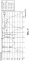
- FIG. 9 is a schematic diagram illustrating reflection coefficient curves and isolation coefficient curves of the first feed source and the second feed source of the antenna apparatus as illustrated in FIG. 5
- FIG. 10 is a system efficiency diagram of the antenna apparatus as illustrated in FIG. 5 under operations of the first feed source and the second feed source.
- curve S 1 is a schematic reflection coefficient curve of the first feed source 210
- curve S2 is a schematic reflection coefficient curve of the second feed source 220
- curve S3 is schematic isolation curves of the first feed source 210 and the second feed source 220.
- curve S4 is a system efficiency curve of the antenna apparatus 200 when the first feed source 210 operates
- curve S5 is a system efficiency curve of the antenna apparatus 200 when the second feed source 220 operates.
- the antenna apparatus 200 when the first feed source 210 feeds an excitation signal to the first radiator 230, the antenna apparatus 200 operates in GPS-L5 band (1.15 GHz - 1.2 GHz), Band N78 (3.4 GHz - 3.6 GHz), and Band N79 (4.8 GHz - 4.9 GHz), and an isolation between the first feed source 210 and the second feed source 220 is good and greater than - 13.5 dB.
- the antenna apparatus 200 may operate in GPS-L5 band, Band N78, and Band N79.
- the system efficiency of the first feed source 210 and the second source 220 is about -9.8 dB when the antenna apparatus 200 operates in GPS-L5 band, is about -43.3 dB when the antenna apparatus 200 operates in Band N78, and is about -3.8 dB when the antenna apparatus 200 operates in Band N79, and thus the radiation performance of the antenna apparatus 200 is good.
- the antenna apparatus 200 when the second feed source 220 feeds an excitation signal to the second radiator 240, the antenna apparatus 200 operates in GPS-L1 band (1.55 GHz - 1.6 GHz), 2.4 GHz Wi-Fi band (2.4 GHz - 2.48 GHz), and Band N41 (2.5 GHz - 2.69 GHz), and the isolation between the first feed source 210 and the second feed source 220 is good and greater than -13.5 dB.
- the antenna apparatus 200 may operate in GPS-L1 band, 2.4 GHz Wi-Fi band, and Band N41.
- the system efficiency of the first feed source 210 and the second feed source 220 is about -3 dB when the antenna apparatus 200 operates in GPS-L1 band, is about -4.1 dB when the antenna apparatus 200 operates in 2.4 GHz Wi-Fi band, and is about -3.2 dB when the antenna apparatus 200 operates in Band N41, and thus the radiation performance of the antenna apparatus 200 is good.
- the first radiator 230 is opposite to the second radiator 240, and the first radiator 230 and the second radiator 240 define the coupling gap 201 therebetween.
- a common-aperture antenna pair can be realized.
- the second filter circuit LC2 and the third filter circuit LC3 each are equivalent to a short circuit in Bands N78 and N79, thus the third current I3 and the fourth current I4 are grounded mainly at the second filter circuit LC2 and the third filter circuit LC3, so that the antenna apparatus 200 can operate in Bands N78 and N79 when the first feed source 210 feeds, and the isolation between the first feed source 210 and the second feed source 220 is also good and does not affect the performance of the antenna apparatus 200.
- the first filter circuit LC1 is equivalent to an open circuit in 2.4 GHz Wi-Fi band and Band N41, thus the second current I2 is grounded at a distal end of the first radiator 230, so that when the first feed source 210 feeds, the antenna apparatus 200 may operate in 2.4 GHz Wi-Fi band and Band N41, and the isolation between the first feed source 210 and the second feed source 220 is also good.
- the first radiator 230 is opposite to the second radiator 240, and the first radiator 230 and the second radiator 240 define the coupling gap 201 therebetween, so that six frequency bands of GPS-L1 band, 2.4 GHz Wi-Fi band, Band N41, GPS-L5 band, Band N78, and Band N79 can be covered in a relatively small space.
- the antenna efficiency of the antenna apparatus 200 in GPS-L1 band may be -3 dB and thus the performance is good.
- the antenna apparatus 200 may also operate in GPS-L5 band, and thus can assist in global position system (GPS) positioning.
- the antenna apparatus 200 may operate in 2.4 GHz Wi-Fi band, Band N41, Band N78, and Band N79, and thus is suitable for the 5th generation mobile communication system (5G).
- 5G 5th generation mobile communication system
- FIG. 11 is a third schematic structural diagram of an antenna apparatus provided in the embodiments of the disclosure.
- Each of the first filter circuit LC1, the second filter circuit LC2, and the third filter circuit LC3 may be a filter circuit.
- a filter circuit may also be known as a filter network.
- the first filter circuit LC1 may filter out a first interference signal between the first feed source 210 and the first radiator 230.
- the first interference signal is an electrical signal other than the first excitation signal, the third excitation signal, and the fourth excitation signal provided by the first feed source 210.
- the first filter circuit LC1 may also prevent the second excitation signal from passing through the first filter circuit LC1, the first filter circuit LC1 is an open circuit and thus can make the first radiator 230 not transmit signals, and the second excitation signal is grounded at the first radiator 230.
- the second filter circuit LC2 may filter out a second interference signal between the second feed source 220 and the second radiator 240.
- the second interference signal is an electrical signal other than the fourth excitation signal and the second excitation signal provided by the second feed source 220.
- the second filter circuit LC2 may also prevent the third excitation signal from passing through the second filter circuit LC2 and thus make the third excitation signal grounded at the second filter circuit LC2.
- the third filter circuit LC3 may filter out a third interference signal between the second feed source 220 and the second radiator 240.
- the third interference signal is an electrical signal other than the fourth excitation signal and the second excitation signal provided by the second feed source 220.
- the third filter circuit LC3 may also prevent the fourth excitation signal from passing through the third filter circuit LC3 and thus make the fourth excitation signal grounded at the third filter circuit LC3.
- the first filter circuit LC1, the second filter circuit LC2, and the third filter circuit LC3 may include circuits composed of capacitors and inductors in any series connection or any parallel connection.
- the first filter circuit LC1 may include, for example, an inductor L1 and a capacitor C1.
- the inductor L1 is connected between and in series with the first feed source 210 and the first radiator 230
- the capacitor C1 is connected between the inductor L1 and the first radiator 230
- the capacitor C1 is grounded. It may be appreciated that an inductance value of the inductor L1 and a capacitance value of the capacitor C1 may be set according to actual needs.
- the second filter circuit LC2 may include, for example, an inductor L2 and a capacitor C2.
- the inductor L2 is connected between and in series with the second feed source 220 and the second radiator 240
- the capacitor C2 is connected between the inductor L2 and the second feed source 220
- the capacitor C2 is grounded. It may be appreciated that an inductance value of the inductor L2 and a capacitance value of the capacitor C2 may be set according to actual needs.
- the third filter circuit LC3 may include, for example, an inductor L3 and a capacitor C3.
- the inductor L3 is connected between and in series with the second feed source 220 and the second radiator 240
- the capacitor C3 is connected between the inductor L3 and the second feed source 220
- the capacitor C3 is grounded. It may be appreciated that an inductance value of the inductor L3 and a capacitance value of the capacitor C3 may be set according to actual needs.
- first filter circuit LC1, the second filter circuit LC2, and the third filter circuit LC3 are only exemplary examples of the first filter circuit LC1, the second filter circuit LC2, and the third filter circuit LC3, and specific structures of the first filter circuit LC1, the second filter circuit LC2, and the third filter circuit LC3 are not limited in the embodiments of the disclosure.
- the antenna apparatus 200 provided in the embodiments of the disclosure may further include a second matching circuit M2 and a first matching circuit M1.
- a matching circuit may also be known as a matching network, a tuning circuit, a tuning network, etc.
- the first matching circuit M1 may be coupled between the first feed source 210 and the first radiator 230.
- the first matching circuit M1 is connected between and in series with the first feed source 210 and the first filter circuit LC1.
- the first matching circuit M1 can be used to realize impedance matching for transmission of excitation signals from the first feed source 210 to the first radiator 230 and the second radiator 240, so that the first feed source 210 can transmit the first excitation signal, the third excitation signal, and the fourth excitation signal to the second radiator 240 and the first radiator 230.
- the second matching circuit M2 may be coupled between the second feed source 220 and the second radiator 240.
- the second matching circuit M2 is connected between and in series with the second feed source 220 and the second filter circuit LC2, and the second matching circuit M2 is also connected between and in series with the second feed source 220 and the third filter circuit LC3.
- the second matching circuit M2 can be used to realize impedance matching for transmission of excitation signals from the second feed source 220 to the second radiator 240 and the first radiator 230, so that the second feed source 220 can transmit the fourth excitation signal and the second excitation signal to the second radiator 240 and the first radiator 230.
- each of the first matching circuit M1 and the second matching circuit M2 may include circuits composed of capacitors and inductors in any series connection or in any parallel connection. Exemplary,
- the first matching circuit M1 may include a capacitor C4 and a capacitor C5.
- the capacitor C4 is connected between and in series with the first feed source 210 and the first filter circuit LC1
- the capacitor C5 is connected between the first feed source 210 and the capacitor C4
- the capacitor C5 is grounded. It may be appreciated that a capacitance value of the capacitor C4 and a capacitance value of the capacitor C5 may be set according to actual needs.
- the second matching circuit M2 may include, for example, a capacitor C6 and a capacitor C7.
- the capacitor C6 is connected between and in series with the second feed source 220 and the second filter circuit LC2, and the capacitor C6 is also connected between and in series with the second feed source 220 and the third filter circuit LC3, the capacitor C7 is connected between the second feed source 220 and the capacitor C6, and the capacitor C7 is grounded. It may be appreciated that a capacitance value of the capacitor C6 and a capacitance value of the capacitor C7 may be set according to actual needs.
- first matching circuit M1 and the second matching circuit M2 are only exemplary examples of the first matching circuit M1 and the second matching circuit M2, and specific structures of the first matching circuit M1 and the second matching circuit M2 are not limited in the embodiments of the disclosure.
- the first radiator 230 and the second radiator 240 may be arranged in the electronic device 100.
- the first radiator 230 and the second radiator 240 may be arranged on the circuit board 130 of the electronic device 100.
- the first radiator 230 and the second radiator 240 may also be arranged on the middle frame 120 of the electronic device 100.
- FIG. 12 is a fourth schematic structural diagram of an antenna apparatus provided in the embodiments of the disclosure.
- the middle frame 120 When the middle frame 120 is made of metal, and the first radiator 230 and the second radiator 240 may include two metal branches on the middle frame 120. As illustrated in FIG. 12 , the middle frame 120 may define a gap 101. With the gap 101, the middle frame 120 forms a first metal branch 121 and a second metal branch 122 opposite the first metal branch 121. The first radiator 230 may include the first metal branch 121, and the second radiator 240 may include the second metal branch 122.
- the above is only one manner in which the first radiator 230 and the second radiator 240 are formed on the middle frame 120.
- the middle frame 120 may define three gaps arranged at intervals, so that the middle frame 120 can form two metal branches opposite each other.
- a manner in which the first radiator 230 and the second radiator 240 are formed on the middle frame 120 is not limited in the embodiments of the disclosure.
- first metal branch 121 and the second metal branch 122 may be formed at a portion of the middle frame 120, such as an upper end, a lower end, a side wall, or a corner, so that the first radiator 230 and the second radiator 240 can be formed at any part of the middle frame 120.
- Specific positions of the first radiator 230 and the second radiator 240 are not limited in the embodiments of the disclosure.
- the first radiator 230 and the second radiator 240 are formed on the middle frame 120, thus the first radiator 230 and the second radiator 240 do not occupy an additional space of the electronic device 100, thereby further realizing the miniaturization of the electronic device 100.
- the first radiator 230 and the second radiator 240 may also be arranged on the rear housing 150 of the electronic device 100.
- FIG. 13 is a fifth schematic structural diagram of an antenna apparatus provided in the embodiments of the disclosure.
- the rear housing 150 is made of metal, for example, as illustrated in FIG. 13
- the rear housing 150 is a metal rear housing 151
- the first radiator 230 and the second radiator 240 may include two metal branches on the metal rear housing 151.
- An annular gap may be defined on the metal rear housing 151 so that an edge of the metal rear housing 151 is separated from the main body of the metal rear housing 151.
- one or more gaps 102 are defined on the edge of the metal rear housing 151 to communicate with the annular gap, so that the metal rear housing 151 can form the third metal branch 152 and the fourth metal branch 153 opposite the third metal branch 152.
- the first radiator 230 may include the third metal branch 152
- the second radiator 240 may include the fourth metal branch 153.
- the metal rear housing 151 may define three L-shaped gaps arranged at intervals, so that the metal rear housing 151 forms two opposite metal branches.
- an inverted T-shaped gap may be defined on the metal rear housing 151, so that the metal rear housing 151 can form two opposite metal branches.
- the above is only an exemplary example of one manner in which the third metal branch 152 and the fourth metal branch 153 are formed in the embodiments of the disclosure, and a manner in which the first radiator 230 and the second radiator 240 are formed on the metal rear housing 151 is not limited in the embodiment of the disclosure.
- the third metal branch 152 and the fourth metal branch 153 may be formed at a portion of the metal rear housing 151, such as an upper end, a lower end, a side wall, or a corner, so that the third metal branch 152 and the fourth metal branch 153 can be formed at any part of the metal rear housing 151.
- Specific positions of the third metal branch 152 and the fourth metal branch 153 are not limited in the embodiments of the disclosure.
- the first radiator 230 and the second radiator 240 are formed on the metal rear housing 151, so that the first radiator 230 and the second radiator 240 are close to the free space, and a clearance zone around the first radiator 230 and the second radiator 240 is relatively large, and thus the excitation signals radiated by the first radiator 230 and the second radiator 240 can be transmitted to the free space with an improved efficiency, and accordingly the radiation performance of the first radiator 230 and the second radiator 240 when transmitting signals can be improved.
Abstract
Description
- This disclosure relates to the field of communication technology, and in particular, to an antenna apparatus and an electronic device.
- With the development of communication technology, electronic devices such as smart phones have more and more functions, as well as more diversified communication modes. For example, generally, the electronic device can support multiple communication modes such as cellular network communication, Wireless Fidelity (Wi-Fi) communication, global positioning system (GPS) communication, Bluetooth (BT) communication, and near field communication (NFC). The realization of all of the above communication functions needs to be based on corresponding antenna apparatuses.
- An antenna apparatus and an electronic device are provided in embodiments of the disclosure. The antenna apparatus can support transmissions of radio frequency signals in at least two frequency bands and occupy a relatively small space, thereby realizing the miniaturization of the antenna apparatus.
- In a first aspect, an antenna apparatus is provided in the embodiments of the disclosure. The antenna apparatus includes a first radiator, a first filter circuit, a first feed source, a second radiator, and a second feed source. The first radiator includes a first feed terminal and a first ground terminal spaced apart from the first feed terminal. The first filter circuit is coupled with the first radiator through the first feed terminal. The first feed source is coupled with the first filter circuit. The first feed source is configured to provide a first excitation signal, and the first excitation signal is configured to excite the first radiator to generate resonance in a first frequency band. The second radiator includes a second feed terminal and a second ground terminal spaced apart from the second feed terminal. A coupling gap is defined between one side of the second radiator where the second feed terminal is located and the first radiator. The second feed source is coupled with the second radiator through the second feed terminal and configured to provide a second excitation signal. The first filter circuit is an open circuit for the second excitation signal, the second excitation signal is at least partially coupled with the first radiator through the coupling gap, and the second excitation signal is configured to excite the first radiator and the second radiator to cooperatively generate resonance in a second frequency band.
- In a second aspect, an electronic device is further provided in the embodiments of the disclosure. The electronic device includes an antenna apparatus. The antenna apparatus includes a first radiator, a first filter circuit, a first feed source, a second radiator, and a second feed source. The first radiator includes a first feed terminal and a first ground terminal spaced apart from the first feed terminal. The first filter circuit is coupled with the first radiator through the first feed terminal. The first feed source is coupled with the first filter circuit, where the first feed source is configured to provide a first excitation signal, and the first excitation signal is configured to excite the first radiator to generate resonance in a first frequency band. The second radiator includes a second feed terminal and a second ground terminal spaced apart from the second feed terminal, where a coupling gap is defined between one side of the second radiator where the second feed terminal is located and the first radiator. The second feed source is coupled with the second radiator through the second feed terminal and configured to provide a second excitation signal. The first filter circuit is an open circuit for the second excitation signal, the second excitation signal is at least partially coupled with the first radiator through the coupling gap, and the second excitation signal is configured to excite the first radiator and the second radiator to cooperatively generate resonance in a second frequency band.
- To describe the technical solutions in the embodiments of the disclosure more clearly, the following briefly introduces the accompanying drawings required for describing the embodiments. Apparently, the accompanying drawings in the following description illustrate some embodiments of the disclosure. Those of ordinary skill in the art may also obtain other drawings based on these accompanying drawings without creative efforts.
-
FIG. 1 is a first schematic structural diagram of an electronic device provided in embodiments of the disclosure. -
FIG. 2 is a first schematic structural diagram of an antenna apparatus provided in embodiments of the disclosure. -
FIG. 3 illustrates a first schematic current diagram of the antenna apparatus as illustrated inFIG. 2 . -
FIG. 4 illustrates a second schematic current diagram of the antenna apparatus as illustrated inFIG. 2 . -
FIG. 5 is a second schematic structural diagram of an antenna apparatus provided in embodiments of the disclosure. -
FIG. 6 illustrates a first schematic current diagram of the antenna apparatus as illustrated inFIG. 5 . -
FIG. 7 illustrates a second schematic current diagram of the antenna apparatus as illustrated inFIG. 5 . -
FIG. 8 illustrates a third schematic current diagram of the antenna apparatus as illustrated inFIG. 5 . -
FIG. 9 is a schematic diagram illustrating reflection coefficient curves and isolation coefficient curves of a first feed source and a second feed source of the antenna apparatus as illustrated inFIG. 5 . -
FIG. 10 is a system efficiency diagram of the antenna apparatus as illustrated inFIG. 5 under operations of a first feed source and a second feed source. -
FIG. 11 is a third schematic structural diagram of an antenna apparatus provided in embodiments of the disclosure. -
FIG. 12 is a fourth schematic structural diagram of an antenna apparatus provided in embodiments of the disclosure. -
FIG. 13 is a fifth schematic structural diagram of an antenna apparatus provided in embodiments of the disclosure. - The technical solutions in embodiments of the disclosure are clearly and completely described hereinafter with reference to
FIGs. 1-13 in the embodiments of the disclosure. Apparently, the described embodiments are merely part rather than all of the embodiments of the disclosure. All other embodiments obtained by those of ordinary skill in the art based on the embodiments of the disclosure without creative efforts are within the scope of the disclosure. - An electronic device is provided in the embodiments of the disclosure. The electronic device may be a smart phone, a tablet computer, etc., or a game device, an augmented reality (AR) device, an automotive apparatus, a data storage apparatus, an audio play apparatus, a video play apparatus, a notebook computer, or a desktop computing device, etc. Refer to
FIG. 1, FIG. 1 is a first schematic structural diagram of an electronic device provided in the embodiments of the disclosure. Theelectronic device 100 includes adisplay screen 110, amiddle frame 120, acircuit board 130, abattery 140, and arear housing 150. - In some embodiments, the
display screen 110 may be disposed on themiddle frame 120, and connected to therear housing 150 through themiddle frame 120 to serve as a display surface of theelectronic device 100. Thedisplay screen 110 is configured to display information such as images and texts. In some embodiments, thedisplay screen 110 may be a liquid crystal display (LCD) screen, an organic light-emitting diode (OLED) display screen, or other types of display screens. - It is noted that, the
display screen 110 may be a full screen, which means that theentire display screen 110 serves as a display region and has no non-display region, or that a non-display region on thedisplay screen 110 only occupies a small area for a user so that thedisplay screen 110 has a relatively high screen-to-body ratio. Alternatively, thedisplay screen 110 may also be a non-full screen, which means that thedisplay screen 110 includes a display region and a non-display region adjacent to the display region. The display region is used to display information, and the non-display region cannot display information. - It is noted that, the
display screen 110 may also be provided with a cover plate (not illustrated) to protect thedisplay screen 110, thereby preventing thedisplay screen 110 from being scratched or from being damaged by water. In some embodiments, the cover plate may be a transparent glass cover plate, so that the user can observe contents displayed on thedisplay screen 110 through the cover plate. It is noted that, the cover plate may be a glass cover plate made of sapphire. - The
middle frame 120 may be a sheet-like structure or a hollow frame structure. Themiddle frame 120 is used to support electronic elements or functional components in theelectronic device 100, so that the electronic elements and functional components of theelectronic device 100 can be mounted in theelectronic device 100. For example, themiddle frame 120 may have structures such as grooves, protrusions, and through holes to facilitate mounting of the electronic elements or functional components of theelectronic device 100. It is noted that, themiddle frame 120 may be made of metal, plastic, or the like. - The
circuit board 130 may be fixed on themiddle frame 120, and is sealed in theelectronic device 100 with aid of therear housing 150. In some embodiments, thecircuit board 130 may be a mainboard of theelectronic device 100. Thecircuit board 130 may be provided with a feed source, where the feed source is electrically connected to an antenna radiator, so that the antenna radiator is capable of transmitting wireless signals. Thecircuit board 130 may be integrated with a processor. In addition, thecircuit board 130 may also be integrated with one or more of functional components such as an earphone jack, an acceleration sensor, a gyroscope, and a motor. Here, thedisplay screen 110 may be electrically connected to thecircuit board 130, so that a display on thedisplay screen 110 can be controlled by the processor on thecircuit board 130. - The
battery 140 is disposed on themiddle frame 120 and is sealed in theelectronic device 100 with aid of therear housing 150. Thebattery 140 is electrically connected to thecircuit board 130 to power theelectronic device 100. In some embodiments, thecircuit board 130 may be provided with a power management circuit. The power management circuit is configured to supply voltages provided by thebattery 140 to various electronic elements in theelectronic device 100. - The
rear housing 150 is connected with themiddle frame 120. For example, therear housing 150 may be bonded to themiddle frame 120 through an adhesive such as double-sided tape to realize connection with themiddle frame 120. In some embodiments, therear housing 150, themiddle frame 120, and thedisplay screen 110 cooperate to seal the electronic elements and functional components of theelectronic device 100 in theelectronic device 100, so that the electronic elements and functional components of theelectronic device 100 can be protected. - In some embodiments, the
electronic device 100 may be further provided with an antenna apparatus. The antenna apparatus is used to realize wireless communication functions of theelectronic device 100, for example, a near field communication function. The antenna apparatus may be disposed in a housing of theelectronic device 100. It may be appreciated that some elements of the antenna apparatus may be integrated on thecircuit board 130. For example, a signal processing chip and a signal processing circuit of the antenna apparatus may be integrated with thecircuit board 130 to realize an electrical connection between the antenna apparatus and thecircuit board 130. In addition, some elements of the antenna apparatus may also be directly arranged in theelectronic device 100. For example, radiators or conductor structures used by the antenna apparatus for radiating signals may be directly arranged on an inner surface of the rear housing. - Refer to
FIG. 2, FIG. 2 is a first schematic structural diagram of an antenna apparatus provided in the embodiments of the disclosure. Theantenna apparatus 200 may include afirst feed source 210, asecond feed source 220, a first filter circuit LC1, afirst radiator 230, asecond radiator 240, and aground plane 250. - The
first feed source 210 and thesecond feed source 220 may be arranged on thecircuit board 130 of theelectronic device 100. Alternatively, thefirst feed source 210 and thesecond feed source 220 may also be arranged on other small boards of theelectronic device 100. Thefirst feed source 210 may feed wireless signals into thefirst radiator 230, and thesecond feed source 220 may feed wireless signals into thesecond radiator 240, so that thefirst feed source 210 and thesecond feed source 220 can transmit wireless signals to free space. - In some embodiments, the
first radiator 230 and thesecond radiator 240 may be antenna radiators made of conductive materials such as metals and conductive silver paste materials. Thefirst radiator 230 is opposite to thesecond radiator 240, so that acoupling gap 201 is defined between thefirst radiator 230 and thesecond radiator 240. - The
first radiator 230 may include a first free end (not illustrated), afirst ground terminal 231, and afirst feed terminal 232 spaced apart from thefirst ground terminal 231. The first free end may be close to thecoupling gap 201. The first free end may be opposite to and spaced apart from thesecond radiator 240. Thefirst ground terminal 231 may be away from thecoupling gap 201. Thefirst feed terminal 232 may be disposed on an end portion of thefirst radiator 230, for example, at the end portion of thefirst radiator 230 where the first free end is located or thefirst ground terminal 231 is located. Alternatively, thefirst feed terminal 232 may also be disposed between the first free end and thefirst ground terminal 231. Thefirst ground terminal 231 may be electrically connected to theground plane 250 to make thefirst radiator 230 grounded. Thefirst feed terminal 232 may be directly or indirectly electrically connected to thefirst feed source 210, so that thefirst feed source 210 can transmit wireless signals to thefirst radiator 230. - It may be appreciated that, the
first radiator 230 may have other feed terminals in addition to the first free end, thefirst ground terminal 231, and thefirst feed terminal 232, so that electrical connections between the first radiator and other electronic elements can be realized. - The
second radiator 240 may include a second free end (not illustrated), asecond ground terminal 241, and asecond feed terminal 242 spaced apart from thesecond ground terminal 241. The second free end may be close to thecoupling gap 201. The second free end may be opposite to and spaced apart from thefirst radiator 230. Thesecond ground terminal 241 may be away from thecoupling gap 201. Thesecond feed terminal 242 may be disposed on an end portion of thesecond radiator 240, for example, at the end portion of thesecond radiator 240 where the second free end is located or thesecond ground terminal 241 is located. Alternatively, thesecond feed terminal 242 may also be disposed between the second free end and thesecond ground terminal 241. Thecoupling gap 201 may be defined between a side of thesecond radiator 240 where thesecond feed terminal 242 is located and thefirst radiator 230. Thesecond ground terminal 241 may be electrically connected to theground plane 250 to make thesecond radiator 240 grounded. Thesecond feed terminal 242 may be directly or indirectly electrically connected to thesecond feed source 220, so that thesecond feed source 220 can transmit wireless signals to thesecond radiator 240. - It may be appreciated that, the
second radiator 240 may have other feed terminals in addition to the first free end, thefirst ground terminal 241, and thefirst feed terminal 242, so that connections between the second radiator and other electronic elements can be realized. - In some embodiments, the first filter circuit LC1 may be disposed on the
circuit board 130 of theelectronic device 100. Alternatively, the first filter circuit LC1 may also be disposed on other small boards of theelectronic device 100. The first filter circuit LC1 may be coupled with thefirst radiator 230, and the first filter circuit LC1 may also be coupled with thefirst feed source 210. That is, the first filter circuit LC1 may be connected between and in series with thefirst feed source 210 and thefirst radiator 230. The first filter circuit LC1 may be coupled with thefirst radiator 230 through thefirst feed terminal 232 to realize an electrical connection between thefirst feed source 210 and thefirst radiator 230. - The
ground plane 250 is used to form the common ground. In some embodiments, theground plane 250 may be formed by a conductor, a printed circuit, or a metal printed layer of theelectronic device 100. For example, theground plane 250 may be on thecircuit board 130 of theelectronic device 100. Theground plane 250 may also be on the housing of theelectronic device 100, for example, theground plane 250 may be formed by themiddle frame 120 of the housing, or theground plane 250 may also be formed by a cover of thebattery 140 of the housing. - It may be appreciated that, the
first radiator 230 and thesecond radiator 240 may be grounded through theground plane 250. Thefirst radiator 230 and thesecond radiator 240 may also be electrically connected to other grounding systems to achieve grounding. - Refer to
FIG. 3 andFIG. 4 in conjunction withFIG. 2 ,FIG. 3 illustrates a first schematic current diagram of the antenna apparatus as illustrated inFIG. 2 , andFIG. 4 illustrates a second schematic current diagram of the antenna apparatus as illustrated inFIG. 2 . In theantenna apparatus 200 provided in the embodiments of the disclosure, thefirst feed source 210 may be coupled with the first filter circuit LC1 and provide a first excitation signal, and the first excitation signal can excite thefirst radiator 230 to generate resonance in a first frequency band. Thesecond feed source 220 may be coupled with thesecond radiator 240 through thesecond feed terminal 242. The second feed source can provide a second excitation signal. The first filter circuit LC1 is an open circuit for the second excitation signal. The second excitation signal is at least partially coupled with thefirst radiator 230 through thecoupling gap 201. The second excitation signal may excite thefirst radiator 230 and thesecond radiator 240 to cooperatively generate resonance in a second frequency band. - Exemplary, as illustrated in
FIG. 3 , when thefirst feed source 210 feeds the first excitation signal to thefirst radiator 230, the first filter circuit LC1 may allow the first excitation signal to pass through, and a first current I1 may flow from thefirst feed source 210 through the first filter circuit LC1 into thefirst radiator 230. The first excitation signal can excite thefirst radiator 230 to generate the resonance in the first frequency band. The first excitation signal may not cause thefirst radiator 230 to couple with thesecond radiator 240. The first current I1 is almost not transmitted in thesecond radiator 240. The first excitation signal is almost only transmitted through thefirst radiator 230 into the free space. It may be appreciated that the first excitation signal in the free space may also be transmitted through thefirst radiator 230 to thefirst feed source 210 through a reverse process of the above process. - It may be appreciated that, a length, an impedance, a resonance point, etc. of the
second radiator 240 may be adjusted, so that when thefirst radiator 230 transmits the first excitation signal, thesecond radiator 240 is not coupled with thefirst radiator 230 through thecoupling gap 201, and thesecond radiator 240 almost not transmits the first excitation signal. - As illustrated in
FIG. 4 , when thesecond feed source 220 feeds the second excitation signal to thesecond radiator 240, a second current I2 may flow from thesecond feed source 220 into thesecond radiator 240. The second current I2 from thesecond radiator 240 may be coupled with thefirst radiator 230 through thecoupling gap 201 and is transmitted in thefirst radiator 230. The first filter circuit LC1 may prevent the second excitation signal from passing through the first filter circuit LC1. The first filter circuit LC1 may be an open circuit for the second excitation signal. The second excitation signal may be at least partially coupled with thefirst radiator 230 through thecoupling gap 201, and the second excitation signal may excite thesecond radiator 240 and thefirst radiator 230 to cooperatively generate the resonance in the second frequency band to radiate the second excitation signal. As such, the second excitation signal and the second current I2 do not flow into thefirst feed source 210 through the first filter circuit LC1. The second current I2 may be grounded at thefirst ground terminal 231 of thefirst radiator 230 and thus a loop is formed. Here, the second current I2 flows from thesecond feed source 220 through thesecond radiator 240 and thefirst radiator 230, thesecond radiator 240 and thefirst radiator 230 cooperatively transmit the second excitation signal. It may be appreciated that, the second excitation signal in the free space may also be transmitted through thefirst radiator 230 and thesecond radiator 240 to thesecond feed source 220 through a reverse process of the above process. - It may be appreciated that, the first filter circuit LC1 is an open circuit for the second excitation signal, which may mean that the first filter circuit LC1 has an infinite resistance under resonance of the second excitation signal, thereby preventing the second excitation signal from flowing into the
first feed source 210. - It may be appreciated that, a length, an impedance, a resonance point, etc. of the
first radiator 230 may be adjusted so that when thesecond radiator 240 transmits the second excitation signal, thefirst radiator 230 can be coupled with thesecond radiator 240 through thecoupling gap 201, thefirst radiator 230 and thesecond radiator 240 can cooperatively transmit the second excitation signal. - Based on above, in the
electronic device 100 and theantenna apparatus 200 provided in the embodiments of the disclosure, thefirst radiator 230 is opposite to thesecond radiator 240, and thefirst radiator 230 and thesecond radiator 240 define thecoupling gap 201 therebetween. With the cooperation of thefirst feed source 210, thesecond feed source 220, and the first filter circuit LC1, thefirst feed source 210 may feed the first excitation signal to thefirst radiator 230, and thefirst radiator 230 may transmit the first excitation signal; thesecond feed source 220 may feed the second excitation signal to thesecond radiator 240, and thus with the aid of the first filter circuit LC1, thesecond radiator 240 and thefirst radiator 230 may cooperatively transmit the second excitation signal. As such, in theantenna apparatus 200 provided in the embodiments of the disclosure, two radiators may transmit at least two kinds of radio frequency signals, thereby not only reducing a space occupied by radiators, but also transmitting wireless signals of more frequency bands, and accordingly realizing the miniaturization of theantenna apparatus 200. - In some embodiments, refer to
FIGs. 5 to 7 ,FIG. 5 is a second schematic structural diagram of an antenna apparatus provided in the embodiments of the disclosure,FIG. 6 illustrates a first schematic current diagram of the antenna apparatus as illustrated inFIG. 5 , andFIG. 7 illustrates a second schematic current diagram of the antenna apparatus as illustrated inFIG. 5 . Theantenna apparatus 200 may further include a second filter circuit LC2 and a third filter circuit LC3. The second filter circuit LC2 and the third filter circuit LC3 may be arranged on thecircuit board 130 of theelectronic device 100. Alternatively, the second filter circuit LC2 and the third filter circuit LC3 may also be arranged on other small boards of theelectronic device 100. The second filter circuit LC2 may be coupled with thesecond feed source 220 and thesecond radiator 240, that is, the second filter circuit LC2 may be connected between and in series with thesecond feed source 220 and thesecond radiator 240. The third filter circuit LC3 may also be coupled with thesecond feed source 220 and thesecond radiator 240, that is, the third filter circuit LC3 may also be connected between and in series with thesecond feed source 220 and thesecond radiator 240. - It may be appreciated that, the second filter circuit LC2 may have a first terminal a1, a second terminal a2, and a third terminal a3. The third terminal a3 may be directly or indirectly electrically connected to the
second feed source 220. The first terminal a1 may be electrically connected to thesecond radiator 240, for example, the first terminal a1 may be electrically connected to thesecond feed terminal 242 of thesecond radiator 240. Alternatively, the first terminal a1 may also be electrically connected to thesecond radiator 240 at any position on a side of thesecond feed terminal 242 close to thefirst radiator 230. The second terminal a2 may be electrically connected to theground plane 250 to make the second filter circuit LC2 grounded. - The third filter circuit LC3 may have a fourth terminal b1, a fifth terminal b2, and a sixth terminal b3. The sixth terminal b3 may be directly or indirectly electrically connected to the
second feed source 220. The fourth terminal b1 may be electrically connected to thesecond radiator 240, for example, the fourth terminal b1 may be electrically connected to thesecond feed terminal 242 of thesecond radiator 240. Alternatively, the fourth terminal b1 may also be electrically connected to thesecond radiator 240 at any position on the side of thesecond feed terminal 242 close to thefirst radiator 230. The fifth terminal b2 may be electrically connected to theground plane 250 to make the third filter circuit LC3 grounded. - The
first feed source 210 may further provide a third excitation signal. When thefirst feed source 210 feeds the third excitation signal to thefirst radiator 230, the third excitation signal may be at least partially coupled with thesecond radiator 240 through thecoupling gap 201, the second filter circuit LC2 may be a short circuit for the third excitation signal, and the third excitation signal may excite thefirst radiator 230 and at least part of thesecond radiator 240 to cooperatively generate resonance in the third frequency band. - As illustrated in
FIG. 6 , the third excitation signal and a third current I3 may flow from thefirst feed source 210 through the first filter circuit LC1 into thefirst radiator 230. The third excitation signal can electromagnetically couple thefirst radiator 230 with thesecond radiator 240. The third excitation signal from thefirst radiator 230 may be coupled with thesecond radiator 240 through thecoupling gap 201 and transmitted in thesecond radiator 240. Here, the second filter circuit LC2 may prevent the third excitation signal from passing through the second filter circuit LC2, and be a short circuit for the third excitation signal. The third excitation signal may excite thefirst radiator 230 and at least part of thesecond radiator 240 to cooperatively generate the resonance in the third frequency band. As such, the third excitation signal and the third current I3 do not flow into thesecond feed source 220 through the second filter circuit LC2, and the third current I3 may be grounded at a ground terminal (for example, the second terminal a2) of the second filter circuit LC2 and thus a loop is formed. Here, the current from thefirst feed source 210 flows through the first filter circuit LC1, thefirst radiator 230, thesecond radiator 240, and the second filter circuit LC2 and then is grounded. Thefirst radiator 230 and thesecond radiator 240 may cooperatively transmit the third excitation signal. It may be appreciated that, the third excitation signal in the free space may also be transmitted through thefirst radiator 230 and thesecond radiator 240 to thefirst feed source 210 through a reverse process of the above process. - In some embodiments, the
first feed source 210 may further provide a fourth excitation signal. When thefirst feed source 210 feeds the fourth excitation signal to thefirst radiator 230, the fourth excitation signal may be at least partially coupled with the second radiator through thecoupling gap 201. The third filter circuit LC3 may be a short circuit for the fourth excitation signal. The fourth excitation signal may excite thefirst radiator 230 and at least part of thesecond radiator 240 to cooperatively generate resonance in a fourth frequency band. - As illustrated in
FIG. 7 , the fourth excitation signal and a fourth current I4 may flow from thefirst feed source 210 through the first filter circuit LC1 into thefirst radiator 230. The fourth excitation signal can couple thefirst radiator 230 with thesecond radiator 240 through thecoupling gap 201. The fourth excitation signal from thefirst radiator 230 may be coupled with thesecond radiator 240 through thecoupling gap 201 and transmitted in thesecond radiator 240. The third filter circuit LC3 may prevent the fourth excitation signal from passing through the third filter circuit LC3. The third filter circuit LC3 may be a short circuit for the fourth excitation signal. The fourth excitation signal may excite thefirst radiator 230 and at least part of thesecond radiator 240 to cooperatively generate resonance in the fourth frequency band. As such, the fourth excitation signal and the fourth current I4 do not flow into thesecond feed source 220 through the third filter circuit LC3, and the fourth current I4 may be grounded at a ground terminal (for example, the second terminal b2) of the third filter circuit LC3 and thus a loop is formed. Here, the current from thefirst feed source 210 flows through the first filter circuit LC1, thefirst radiator 230, thesecond radiator 240, and the third filter circuit LC3, and then is grounded. Thefirst radiator 230 and thesecond radiator 240 may cooperatively transmit the fourth excitation signal. It may be appreciated that, the fourth excitation signal in the free space may also be transmitted through thefirst radiator 230 and thesecond radiator 240 to thefirst feed source 210 through a reverse process of the above process. - It may be appreciated that, the second filter circuit LC2 is a short circuit for the third excitation signal, which may mean that the second filter circuit LC2 has an infinitesimal resistance in a frequency band of the third excitation signal, so that the third excitation signal can be grounded. The third filter circuit LC3 is a short circuit for the fourth excitation signal, which may mean that the third filter circuit LC3 an infinitesimal resistance in a frequency band of the fourth excitation signal, so that the fourth excitation signal can be grounded.
- It may be appreciated that, a length, an impedance, and a resonance point of the
second radiator 240 as well as resistance values, capacitance values, etc. of the second filter circuit LC2 and the third filter circuit LC3 may be adjusted, so that when thefirst radiator 230 transmits the third excitation signal and the fourth excitation signal, thesecond radiator 240 may be coupled with thefirst radiator 230 through thecoupling gap 201, and thesecond radiator 240 can generate the resonance in the third frequency band and the resonance in the fourth frequency band. - It may be appreciated that, the antenna apparatus may only include the second filter circuit LC2, or may only include the third filter circuit LC3, or may include both the second filter circuit LC2 and the third filter circuit LC3.
- It may be appreciated that, a distance between the
second feed terminal 242 of thesecond radiator 240 and thefirst radiator 230 may be adjusted to adjust a frequency range of the third excitation signal and a frequency range of the fourth excitation signal. Exemplary, when a distance between thesecond feed terminal 242 and thecoupling gap 201 is smaller than a distance between thesecond feed terminal 242 and thesecond ground terminal 241, thesecond feed terminal 242 is relatively close to thefirst radiator 230, so that thefirst radiator 230, thesecond radiator 240, and the second filter circuit LC2 and the third filter circuit LC3 that are electrically connected to thesecond feed terminal 242 can resonate to generate the third excitation signal and the fourth excitation signal in a relatively high frequency band, for example, Band N78 (3.4 GHz to 3.6 GHz) or Band N79 (4.8 GHz to 4.9 GHz). - In some embodiments, refer to
FIG. 5 andFIG. 8, FIG. 8 illustrates a third schematic current diagram of the antenna apparatus as illustrated inFIG. 5 . Thesecond feed source 220 may further provide a fifth excitation signal, and the fifth excitation signal may excite thesecond radiator 240 to generate resonance in the fifth frequency band. - Exemplary, as illustrated in
FIG. 8 , when thesecond feed source 220 feeds the fifth excitation signal to thesecond radiator 240, a fifth current 15 may flow from thesecond feed source 220 to thesecond radiator 240. The fifth excitation signal can excite thesecond radiator 240 to generate resonance in a fifth frequency band. The fifth excitation signal does not cause thesecond radiator 240 to couple with thefirst radiator 230. The fifth current 15 is almost not transmitted in thefirst radiator 230. The fifth excitation signal is almost only transmitted through thesecond radiator 240 into the free space. It may be appreciated that the fifth excitation signal in the free space may also be transmitted through thesecond radiator 240 to thesecond feed source 220 through a reverse process of the above process. - It may be appreciated that, the length, the impedance, the resonance point, etc. of the
first radiator 230 may be adjusted so that when thesecond radiator 240 transmits the fifth excitation signal, thefirst radiator 230 is not coupled with thesecond radiator 240 through thecoupling gap 201, and thefirst radiator 230 almost does not transmit the first excitation signal. - Based on above, in the antenna apparatus provided in the embodiments of the disclosure, when the
first feed source 210 feeds an excitation signal to thefirst radiator 230, with the aid of the first filter circuit LC1, the second filter circuit LC2, and the third filter circuit LC3, thefirst radiator 230 may transmit the first excitation signal, thefirst radiator 230 and thesecond radiator 240 may cooperatively transmit the third excitation signal, and thefirst radiator 230 and thesecond radiator 240 may also cooperatively transmit the fourth excitation signal. When thesecond feed source 220 feeds the second excitation signal to thesecond radiator 240, thesecond radiator 240 may transmit the fifth excitation signal, and with the aid of the first filter circuit LC1, the second filter circuit LC2, and the third filter circuit LC3, thefirst radiator 230 and thesecond radiator 240 may cooperatively transmit the second excitation signal. - It may be appreciated that, in the
antenna apparatus 200 provided in the embodiments of the disclosure, thesecond feed source 220 and thefirst feed source 210 may operate separately or simultaneously. That is, theantenna apparatus 200 may separately implement the above-mentioned process of feeding an excitation signal to thefirst radiator 230 by thefirst feed source 210, theantenna apparatus 200 may also separately implement the above-mentioned process of feeding an excitation signal to thesecond radiator 240 by thesecond feed source 220, and theantenna apparatus 200 may also simultaneously implement the above-mentioned process of feeding the excitation signal to thefirst radiator 230 by thefirst feed source 210 and the above-mentioned process of feeding the excitation signal to thesecond radiator 240 by thesecond feed source 220. - When the
first feed source 210 feeds the excitation signal to thefirst radiator 230 and thesecond feed source 220 feeds the excitation signal to thesecond radiator 240, thefirst radiator 230 may transmit the first excitation signal, thesecond radiator 240 may transmit the fifth excitation signal, and thefirst radiator 230 and thesecond radiator 240 may cooperatively transmit the second excitation signal, the third excitation signal, and the fourth excitation signal. When transmitting the second excitation signal, thefirst radiator 230 and thesecond radiator 240 may be grounded at thefirst ground terminal 231 of thefirst radiator 230. When transmitting the third excitation signal, thefirst radiator 230 and thesecond radiator 240 may be grounded at the second terminal a2 of the second filter circuit LC2. When transmitting the fourth excitation signal, thefirst radiator 230 and thesecond radiator 240 may be grounded at the fifth terminal b2 of the third filter circuit LC3. - In the
electronic device 100 and theantenna apparatus 200 provided in the embodiments of the disclosure, thefirst radiator 230 is opposite to thesecond radiator 240, thefirst radiator 230 and thesecond radiator 240 define thecoupling gap 201 therebetween. With the cooperation of thesecond feed source 220, thefirst feed source 210, the first filter circuit LC1, the second filter circuit LC2, and the third filter circuit LC3, thefirst radiator 230 may transmit the first excitation signal, thesecond radiator 240 may transmit the fifth excitation signal, and thesecond radiator 240 and thefirst radiator 230 may cooperatively transmit the second excitation signal, the third excitation signal, and the fourth excitation signal. As such, in theantenna apparatus 200 provided in the embodiments of the disclosure, two radiators may transmit at least five kinds of radio frequency signals, thereby not only reducing a space occupied by radiators, but also transmitting wireless signals of more frequency bands, and accordingly realizing the miniaturization of theantenna apparatus 200. - In some embodiments, a length of the
first radiator 230 and a length of thesecond radiator 240 may be adjusted to make the first excitation signal differ from the fifth excitation signal, and an impedance of the second filter circuit LC2 and an impedance of the third filter circuit LC3 may be adjusted to make the second excitation signal, the third excitation signal, and the fourth excitation signal differ from one another. As such, the first excitation signal, the fifth excitation signal, the second excitation signal, the third excitation signal, and the fourth excitation signal may be made different from one another. - Exemplary, the first excitation signal excites the
first radiator 230 to generate the resonance in the first frequency band ranging from 1.15 GHz to 1.2 GHz, the fifth excitation signal excites thesecond radiator 240 to generate the resonance in the fifth frequency band ranging from 1.55 GHz to 1.6 GHz, the second excitation signal excites thefirst radiator 230 and thesecond radiator 240 to cooperatively generate the resonance in the second frequency band ranging from 2.4 GHz to 2.69 GHz, the third excitation signal excites thefirst radiator 230 and thesecond radiator 240 to cooperatively generate the resonance in the third frequency band ranging from 4.8 GHz to 4.9 GHz, and the fourth excitation signal ranges from 3.4 GHz to 3.6 GHz. Thus, when thefirst feed source 210 feeds an excitation signal to thefirst radiator 230, thefirst radiator 230 may transmit signals in GPS-L5 band (1.15 GHz ~ 1.2 GHz), and thesecond radiator 240 and thefirst radiator 230 may cooperatively transmit signals in Band N78 (3.4 GHz - 3.6 GHz) and signals in Band N79 (4.8 GHz - 4.9 GHz). When thesecond feed source 220 feeds an excitation signal to thesecond radiator 240, thesecond radiator 240 may transmit signals in GPS-L1 band (1.55 GHz - 1.6 GHz), and thesecond radiator 240 and thefirst radiator 230 may cooperatively transmit signals in 2.4 GHz Wi-Fi band (2.4 GHz - 2.48 GHz) and signals in Band N41 (2.5 GHz - 2.69 GHz). - Refer to
FIG. 9 andFIG. 10 in conjunction withFIG. 5 ,FIG. 9 is a schematic diagram illustrating reflection coefficient curves and isolation coefficient curves of the first feed source and the second feed source of the antenna apparatus as illustrated inFIG. 5 , andFIG. 10 is a system efficiency diagram of the antenna apparatus as illustrated inFIG. 5 under operations of the first feed source and the second feed source. - As illustrated in
FIG. 9 ,curve S 1 is a schematic reflection coefficient curve of thefirst feed source 210, curve S2 is a schematic reflection coefficient curve of thesecond feed source 220, and curve S3 is schematic isolation curves of thefirst feed source 210 and thesecond feed source 220. As illustrated inFIG. 10 , curve S4 is a system efficiency curve of theantenna apparatus 200 when thefirst feed source 210 operates, and curve S5 is a system efficiency curve of theantenna apparatus 200 when thesecond feed source 220 operates. - As can be seen from curve S1 and curve S3, when the
first feed source 210 feeds an excitation signal to thefirst radiator 230, theantenna apparatus 200 operates in GPS-L5 band (1.15 GHz - 1.2 GHz), Band N78 (3.4 GHz - 3.6 GHz), and Band N79 (4.8 GHz - 4.9 GHz), and an isolation between thefirst feed source 210 and thesecond feed source 220 is good and greater than - 13.5 dB. Thus, it can be seen that, theantenna apparatus 200 may operate in GPS-L5 band, Band N78, and Band N79. Further, as can be seen from curve S4, the system efficiency of thefirst feed source 210 and thesecond source 220 is about -9.8 dB when theantenna apparatus 200 operates in GPS-L5 band, is about -43.3 dB when theantenna apparatus 200 operates in Band N78, and is about -3.8 dB when theantenna apparatus 200 operates in Band N79, and thus the radiation performance of theantenna apparatus 200 is good. - As can be seen from curve S2 and curve S3, when the
second feed source 220 feeds an excitation signal to thesecond radiator 240, theantenna apparatus 200 operates in GPS-L1 band (1.55 GHz - 1.6 GHz), 2.4 GHz Wi-Fi band (2.4 GHz - 2.48 GHz), and Band N41 (2.5 GHz - 2.69 GHz), and the isolation between thefirst feed source 210 and thesecond feed source 220 is good and greater than -13.5 dB. Thus, it can be seen that, theantenna apparatus 200 may operate in GPS-L1 band, 2.4 GHz Wi-Fi band, and Band N41. Further, as can be seen from curve S5, the system efficiency of thefirst feed source 210 and thesecond feed source 220 is about -3 dB when theantenna apparatus 200 operates in GPS-L1 band, is about -4.1 dB when theantenna apparatus 200 operates in 2.4 GHz Wi-Fi band, and is about -3.2 dB when theantenna apparatus 200 operates in Band N41, and thus the radiation performance of theantenna apparatus 200 is good. - In the
antenna apparatus 200 and theelectronic device 100 provided in the embodiments of the disclosure, thefirst radiator 230 is opposite to thesecond radiator 240, and thefirst radiator 230 and thesecond radiator 240 define thecoupling gap 201 therebetween. With aid of feeding function of thefirst feed source 210 and thesecond feed source 220, a common-aperture antenna pair can be realized. The second filter circuit LC2 and the third filter circuit LC3 each are equivalent to a short circuit in Bands N78 and N79, thus the third current I3 and the fourth current I4 are grounded mainly at the second filter circuit LC2 and the third filter circuit LC3, so that theantenna apparatus 200 can operate in Bands N78 and N79 when thefirst feed source 210 feeds, and the isolation between thefirst feed source 210 and thesecond feed source 220 is also good and does not affect the performance of theantenna apparatus 200. In addition, the first filter circuit LC1 is equivalent to an open circuit in 2.4 GHz Wi-Fi band and Band N41, thus the second current I2 is grounded at a distal end of thefirst radiator 230, so that when thefirst feed source 210 feeds, theantenna apparatus 200 may operate in 2.4 GHz Wi-Fi band and Band N41, and the isolation between thefirst feed source 210 and thesecond feed source 220 is also good. - In the
antenna apparatus 200 and theelectronic device 100 provided in the embodiments of the disclosure, thefirst radiator 230 is opposite to thesecond radiator 240, and thefirst radiator 230 and thesecond radiator 240 define thecoupling gap 201 therebetween, so that six frequency bands of GPS-L1 band, 2.4 GHz Wi-Fi band, Band N41, GPS-L5 band, Band N78, and Band N79 can be covered in a relatively small space. The antenna efficiency of theantenna apparatus 200 in GPS-L1 band may be -3 dB and thus the performance is good. In addition, theantenna apparatus 200 may also operate in GPS-L5 band, and thus can assist in global position system (GPS) positioning. Theantenna apparatus 200 may operate in 2.4 GHz Wi-Fi band, Band N41, Band N78, and Band N79, and thus is suitable for the 5th generation mobile communication system (5G). - In some embodiments, refer to
FIG. 11 again,FIG. 11 is a third schematic structural diagram of an antenna apparatus provided in the embodiments of the disclosure. Each of the first filter circuit LC1, the second filter circuit LC2, and the third filter circuit LC3 may be a filter circuit. A filter circuit may also be known as a filter network. - When the first filter circuit LC1 is disposed between the
first feed source 210 and thefirst radiator 230, the first filter circuit LC1 may filter out a first interference signal between thefirst feed source 210 and thefirst radiator 230. The first interference signal is an electrical signal other than the first excitation signal, the third excitation signal, and the fourth excitation signal provided by thefirst feed source 210. Meanwhile, the first filter circuit LC1 may also prevent the second excitation signal from passing through the first filter circuit LC1, the first filter circuit LC1 is an open circuit and thus can make thefirst radiator 230 not transmit signals, and the second excitation signal is grounded at thefirst radiator 230. - When the second filter circuit LC2 is disposed between the
second feed source 220 and thesecond radiator 240, the second filter circuit LC2 may filter out a second interference signal between thesecond feed source 220 and thesecond radiator 240. The second interference signal is an electrical signal other than the fourth excitation signal and the second excitation signal provided by thesecond feed source 220. Meanwhile, the second filter circuit LC2 may also prevent the third excitation signal from passing through the second filter circuit LC2 and thus make the third excitation signal grounded at the second filter circuit LC2. - When the third filter circuit LC3 is disposed between the
second feed source 220 and thesecond radiator 240, the third filter circuit LC3 may filter out a third interference signal between thesecond feed source 220 and thesecond radiator 240. The third interference signal is an electrical signal other than the fourth excitation signal and the second excitation signal provided by thesecond feed source 220. Meanwhile, the third filter circuit LC3 may also prevent the fourth excitation signal from passing through the third filter circuit LC3 and thus make the fourth excitation signal grounded at the third filter circuit LC3. - It may be appreciated that, the first filter circuit LC1, the second filter circuit LC2, and the third filter circuit LC3 may include circuits composed of capacitors and inductors in any series connection or any parallel connection.
- Exemplarily, as illustrated in
FIG. 11 , the first filter circuit LC1 may include, for example, an inductor L1 and a capacitor C1. In some embodiments, the inductor L1 is connected between and in series with thefirst feed source 210 and thefirst radiator 230, the capacitor C1 is connected between the inductor L1 and thefirst radiator 230, and the capacitor C1 is grounded. It may be appreciated that an inductance value of the inductor L1 and a capacitance value of the capacitor C1 may be set according to actual needs. - The second filter circuit LC2 may include, for example, an inductor L2 and a capacitor C2. In some embodiments, the inductor L2 is connected between and in series with the
second feed source 220 and thesecond radiator 240, the capacitor C2 is connected between the inductor L2 and thesecond feed source 220, and the capacitor C2 is grounded. It may be appreciated that an inductance value of the inductor L2 and a capacitance value of the capacitor C2 may be set according to actual needs. - The third filter circuit LC3 may include, for example, an inductor L3 and a capacitor C3. In some embodiments, the inductor L3 is connected between and in series with the
second feed source 220 and thesecond radiator 240, the capacitor C3 is connected between the inductor L3 and thesecond feed source 220, and the capacitor C3 is grounded. It may be appreciated that an inductance value of the inductor L3 and a capacitance value of the capacitor C3 may be set according to actual needs. - It may be appreciated that, the above are only exemplary examples of the first filter circuit LC1, the second filter circuit LC2, and the third filter circuit LC3, and specific structures of the first filter circuit LC1, the second filter circuit LC2, and the third filter circuit LC3 are not limited in the embodiments of the disclosure.
- In some embodiments, refer to
FIG. 5 andFIG. 11 again, in order to further enhance the performance of theantenna apparatus 200, theantenna apparatus 200 provided in the embodiments of the disclosure may further include a second matching circuit M2 and a first matching circuit M1. It may be appreciated that, a matching circuit may also be known as a matching network, a tuning circuit, a tuning network, etc. - As illustrated in
FIG. 5 , the first matching circuit M1 may be coupled between thefirst feed source 210 and thefirst radiator 230. For example, the first matching circuit M1 is connected between and in series with thefirst feed source 210 and the first filter circuit LC1. The first matching circuit M1 can be used to realize impedance matching for transmission of excitation signals from thefirst feed source 210 to thefirst radiator 230 and thesecond radiator 240, so that thefirst feed source 210 can transmit the first excitation signal, the third excitation signal, and the fourth excitation signal to thesecond radiator 240 and thefirst radiator 230. - The second matching circuit M2 may be coupled between the
second feed source 220 and thesecond radiator 240. For example, the second matching circuit M2 is connected between and in series with thesecond feed source 220 and the second filter circuit LC2, and the second matching circuit M2 is also connected between and in series with thesecond feed source 220 and the third filter circuit LC3. The second matching circuit M2 can be used to realize impedance matching for transmission of excitation signals from thesecond feed source 220 to thesecond radiator 240 and thefirst radiator 230, so that thesecond feed source 220 can transmit the fourth excitation signal and the second excitation signal to thesecond radiator 240 and thefirst radiator 230. - It may be appreciated that, each of the first matching circuit M1 and the second matching circuit M2 may include circuits composed of capacitors and inductors in any series connection or in any parallel connection. Exemplary,
- For example, as illustrated in
FIG. 11 , the first matching circuit M1 may include a capacitor C4 and a capacitor C5. In some embodiments, the capacitor C4 is connected between and in series with thefirst feed source 210 and the first filter circuit LC1, the capacitor C5 is connected between thefirst feed source 210 and the capacitor C4, and the capacitor C5 is grounded. It may be appreciated that a capacitance value of the capacitor C4 and a capacitance value of the capacitor C5 may be set according to actual needs. - The second matching circuit M2 may include, for example, a capacitor C6 and a capacitor C7. The capacitor C6 is connected between and in series with the
second feed source 220 and the second filter circuit LC2, and the capacitor C6 is also connected between and in series with thesecond feed source 220 and the third filter circuit LC3, the capacitor C7 is connected between thesecond feed source 220 and the capacitor C6, and the capacitor C7 is grounded. It may be appreciated that a capacitance value of the capacitor C6 and a capacitance value of the capacitor C7 may be set according to actual needs. - It may be appreciated that, the above are only exemplary examples of the first matching circuit M1 and the second matching circuit M2, and specific structures of the first matching circuit M1 and the second matching circuit M2 are not limited in the embodiments of the disclosure.
- In some embodiments, the
first radiator 230 and thesecond radiator 240 may be arranged in theelectronic device 100. For example, thefirst radiator 230 and thesecond radiator 240 may be arranged on thecircuit board 130 of theelectronic device 100. Thefirst radiator 230 and thesecond radiator 240 may also be arranged on themiddle frame 120 of theelectronic device 100. For example, refer toFIG. 12, FIG. 12 is a fourth schematic structural diagram of an antenna apparatus provided in the embodiments of the disclosure. - When the
middle frame 120 is made of metal, and thefirst radiator 230 and thesecond radiator 240 may include two metal branches on themiddle frame 120. As illustrated inFIG. 12 , themiddle frame 120 may define agap 101. With thegap 101, themiddle frame 120 forms afirst metal branch 121 and asecond metal branch 122 opposite thefirst metal branch 121. Thefirst radiator 230 may include thefirst metal branch 121, and thesecond radiator 240 may include thesecond metal branch 122. - It may be appreciated that, the above is only one manner in which the
first radiator 230 and thesecond radiator 240 are formed on themiddle frame 120. For example, themiddle frame 120 may define three gaps arranged at intervals, so that themiddle frame 120 can form two metal branches opposite each other. A manner in which thefirst radiator 230 and thesecond radiator 240 are formed on themiddle frame 120 is not limited in the embodiments of the disclosure. - It may be appreciated that, the
first metal branch 121 and thesecond metal branch 122 may be formed at a portion of themiddle frame 120, such as an upper end, a lower end, a side wall, or a corner, so that thefirst radiator 230 and thesecond radiator 240 can be formed at any part of themiddle frame 120. Specific positions of thefirst radiator 230 and thesecond radiator 240 are not limited in the embodiments of the disclosure. - In the
antenna apparatus 200 provided in the embodiments of the disclosure, thefirst radiator 230 and thesecond radiator 240 are formed on themiddle frame 120, thus thefirst radiator 230 and thesecond radiator 240 do not occupy an additional space of theelectronic device 100, thereby further realizing the miniaturization of theelectronic device 100. - In some embodiments, the
first radiator 230 and thesecond radiator 240 may also be arranged on therear housing 150 of theelectronic device 100. For example, refer toFIG. 13, FIG. 13 is a fifth schematic structural diagram of an antenna apparatus provided in the embodiments of the disclosure. When therear housing 150 is made of metal, for example, as illustrated inFIG. 13 , therear housing 150 is a metalrear housing 151, and thefirst radiator 230 and thesecond radiator 240 may include two metal branches on the metalrear housing 151. An annular gap may be defined on the metalrear housing 151 so that an edge of the metalrear housing 151 is separated from the main body of the metalrear housing 151. Further, one ormore gaps 102 are defined on the edge of the metalrear housing 151 to communicate with the annular gap, so that the metalrear housing 151 can form thethird metal branch 152 and thefourth metal branch 153 opposite thethird metal branch 152. Thefirst radiator 230 may include thethird metal branch 152, and thesecond radiator 240 may include thefourth metal branch 153. - It may be appreciated that, the above is only an embodiment in which the
first radiator 230 and thesecond radiator 240 are formed on the metalrear housing 151. For example, the metalrear housing 151 may define three L-shaped gaps arranged at intervals, so that the metalrear housing 151 forms two opposite metal branches. For another example, an inverted T-shaped gap may be defined on the metalrear housing 151, so that the metalrear housing 151 can form two opposite metal branches. It may be appreciated that the above is only an exemplary example of one manner in which thethird metal branch 152 and thefourth metal branch 153 are formed in the embodiments of the disclosure, and a manner in which thefirst radiator 230 and thesecond radiator 240 are formed on the metalrear housing 151 is not limited in the embodiment of the disclosure. - It may be appreciated that, the
third metal branch 152 and thefourth metal branch 153 may be formed at a portion of the metalrear housing 151, such as an upper end, a lower end, a side wall, or a corner, so that thethird metal branch 152 and thefourth metal branch 153 can be formed at any part of the metalrear housing 151. Specific positions of thethird metal branch 152 and thefourth metal branch 153 are not limited in the embodiments of the disclosure. - In the
antenna apparatus 200 of embodiments of the disclosure, thefirst radiator 230 and thesecond radiator 240 are formed on the metalrear housing 151, so that thefirst radiator 230 and thesecond radiator 240 are close to the free space, and a clearance zone around thefirst radiator 230 and thesecond radiator 240 is relatively large, and thus the excitation signals radiated by thefirst radiator 230 and thesecond radiator 240 can be transmitted to the free space with an improved efficiency, and accordingly the radiation performance of thefirst radiator 230 and thesecond radiator 240 when transmitting signals can be improved. - It is noted that, the terms such as "first" and "second" used in the disclosure are only used for distinguishing similar objects and cannot be understood as explicitly or implicitly indicating relative importance or implicitly indicating the number of technical features referred to herein.
- The antenna apparatus and the electronic device provided in the embodiments of the disclosure are described in detail above, specific examples are used herein to describe the principle and embodiment manners of the disclosure. The above embodiments is merely described to help understand the disclosure. Apparently, the described embodiments are merely some rather than all embodiments of the disclosure. All other embodiments obtained by those of ordinary skill in the art based on the embodiments of the disclosure without creative efforts shall fall within the protection scope of the disclosure. Meanwhile, those skilled in the art may make modifications to the specific embodiment manners and the application scope according to the idea of the disclosure. In summary, the contents of the specification should not be construed as limiting the disclosure.
Claims (20)
- An antenna apparatus, comprising:a first radiator comprising a first feed terminal and a first ground terminal spaced apart from the first feed terminal;a first filter circuit coupled with the first radiator through the first feed terminal;a first feed source coupled with the first filter circuit, wherein the first feed source is configured to provide a first excitation signal, and the first excitation signal is configured to excite the first radiator to generate resonance in a first frequency band;a second radiator comprising a second feed terminal and a second ground terminal spaced apart from the second feed terminal, wherein a coupling gap is defined between one side of the second radiator where the second feed terminal is located and the first radiator; anda second feed source coupled with the second radiator through the second feed terminal and configured to provide a second excitation signal; whereinthe first filter circuit is an open circuit for the second excitation signal, the second excitation signal is at least partially coupled with the first radiator through the coupling gap, and the second excitation signal is configured to excite the first radiator and the second radiator to cooperatively generate resonance in a second frequency band.
- The antenna apparatus of claim 1, further comprising a second filter circuit, whereinthe second filter circuit has a first terminal and a second terminal, wherein the first terminal of the second filter circuit is coupled with the second radiator at the second feed terminal or at any position on a side of the second feed terminal close to the first radiator, and the second terminal of the second filter circuit is grounded; andthe first feed source is further configured to provide a third excitation signal, wherein the third excitation signal is at least partially coupled with the second radiator through the coupling gap, the second filter circuit is a short circuit for the third excitation signal, and the third excitation signal is configured to excite the first radiator and at least part of the second radiator to cooperatively generate resonance in a third frequency band.
- The antenna apparatus of claim 2, wherein a distance between the second feed terminal and the coupling gap is smaller than a distance between the second feed terminal and the second ground terminal.
- The antenna apparatus of claim 2, further comprising a third filter circuit, whereinthe third filter circuit has a first terminal and a second terminal, wherein the first terminal of the third filter circuit is coupled with the second radiator at the second feed terminal or at any position on a side of the second feed terminal close to the first radiator, and the second terminal of the third filter circuit is grounded; andthe first feed source is further configured to provide a fourth excitation signal, wherein the fourth excitation signal is at least partially coupled with the second radiator through the coupling gap, the third filter circuit is a short circuit for the fourth excitation signal, and the fourth excitation signal is configured to excite the first radiator and at least part of the second radiator to cooperatively generate resonance in a fourth frequency band.
- The antenna apparatus of claim 4, wherein the first frequency band ranges from 1.15 GHz to 1.2 GHz, the third frequency band ranges from 4.8 GHz to 4.9 GHz, and the fourth frequency band ranges from 3.4 GHz to 3.6 GHz.
- The antenna apparatus of claim 1, wherein the second feed source is further configured to provide a fifth excitation signal, wherein the fifth excitation signal is configured to excite the second radiator to generate resonance in a fifth frequency band.
- The antenna apparatus of claim 6, wherein the second frequency band ranges from 2.4 GHz to 2.69 GHz, and the fifth frequency band ranges from 1.55 GHz to 1.6 GHz.
- The antenna apparatus of claim 1, further comprising a first matching circuit coupled between the first feed source and the first radiator, and configured to perform impedance matching for an excitation signal provided by the first feed source.
- The antenna apparatus of claim 1, further comprising a second matching circuit coupled between the second feed source and the second radiator, and configured to perform impedance matching for an excitation signal provided by the second feed source.
- An electronic device, comprising an antenna apparatus, wherein the antenna apparatus comprises:a first radiator comprising a first feed terminal and a first ground terminal spaced apart from the first feed terminal;a first filter circuit coupled with the first radiator through the first feed terminal;a first feed source coupled with the first filter circuit, wherein the first feed source is configured to provide a first excitation signal, and the first excitation signal is configured to excite the first radiator to generate resonance in a first frequency band;a second radiator comprising a second feed terminal and a second ground terminal spaced apart from the second feed terminal, wherein a coupling gap is defined between one side of the second radiator where the second feed terminal is located and the first radiator; anda second feed source coupled with the second radiator through the second feed terminal and configured to provide a second excitation signal; whereinthe first filter circuit is an open circuit for the second excitation signal, the second excitation signal is at least partially coupled with the first radiator through the coupling gap, and the second excitation signal is configured to excite the first radiator and the second radiator to cooperatively generate resonance in a second frequency band.
- The electronic device of claim 10, further comprising a second filter circuit, whereinthe second filter circuit has a first terminal and a second terminal, wherein the first terminal of the second filter circuit is coupled with the second radiator at the second feed terminal or at any position on a side of the second feed terminal close to the first radiator, and the second terminal of the second filter circuit is grounded; andthe first feed source is further configured to provide a third excitation signal, wherein the third excitation signal is at least partially coupled with the second radiator through the coupling gap, the second filter circuit is a short circuit for the third excitation signal, and the third excitation signal is configured to excite the first radiator and at least part of the second radiator to cooperatively generate resonance in a third frequency band.
- The electronic device of claim 11, wherein a distance between the second feed terminal and the coupling gap is smaller than a distance between the second feed terminal and the second ground terminal.
- The electronic device of claim 11, further comprising a third filter circuit, whereinthe third filter circuit has a first terminal and a second terminal, wherein the first terminal of the third filter circuit is coupled with the second radiator at the second feed terminal or at any position on a side of the second feed terminal close to the first radiator, and the second terminal of the third filter circuit is grounded; andthe first feed source is further configured to provide a fourth excitation signal, wherein the fourth excitation signal is at least partially coupled with the second radiator through the coupling gap, the third filter circuit is a short circuit for the fourth excitation signal, and the fourth excitation signal is configured to excite the first radiator and at least part of the second radiator to cooperatively generate resonance in a fourth frequency band.
- The electronic device of claim 13, wherein the first frequency band ranges from 1.15 GHz to 1.2 GHz, the third frequency band ranges from 4.8 GHz to 4.9 GHz, and the fourth frequency band ranges from 3.4 GHz to 3.6 GHz.
- The electronic device of claim 10, wherein the second feed source is further configured to provide a fifth excitation signal, wherein the fifth excitation signal is configured to excite the second radiator to generate resonance in a fifth frequency band.
- The electronic device of claim 15, wherein the second frequency band ranges from 2.4 GHz to 2.69 GHz, and the fifth frequency band ranges from 1.55 GHz to 1.6 GHz.
- The electronic device of claim 10, further comprising a first matching circuit coupled between the first feed source and the first radiator, and configured to perform impedance matching for an excitation signal provided by the first feed source.
- The electronic device of claim 10, further comprising a second matching circuit coupled between the second feed source and the second radiator, and configured to perform impedance matching for an excitation signal provided by the second feed source.
- The electronic device of claim 10, further comprising a middle frame, wherein the middle frame comprises a first metal branch and a second metal branch spaced apart from the first metal branch, and the first radiator comprises the first metal branch, and the second radiator comprises the second metal branch.
- The electronic device of claim 10, further comprising a metal rear housing, wherein the metal rear housing defines gaps to respectively form a third metal branch and a fourth metal branch, the first radiator comprises the third metal branch, and the second radiator comprises the fourth metal branch.
Applications Claiming Priority (1)
| Application Number | Priority Date | Filing Date | Title |
|---|---|---|---|
| PCT/CN2020/119433 WO2022067680A1 (en) | 2020-09-30 | 2020-09-30 | Antenna apparatus and electronic device |
Publications (2)
| Publication Number | Publication Date |
|---|---|
| EP4224630A1 true EP4224630A1 (en) | 2023-08-09 |
| EP4224630A4 EP4224630A4 (en) | 2023-11-22 |
Family
ID=80949364
Family Applications (1)
| Application Number | Title | Priority Date | Filing Date |
|---|---|---|---|
| EP20955705.7A Pending EP4224630A4 (en) | 2020-09-30 | 2020-09-30 | Antenna apparatus and electronic device |
Country Status (3)
| Country | Link |
|---|---|
| EP (1) | EP4224630A4 (en) |
| CN (1) | CN115777163A (en) |
| WO (1) | WO2022067680A1 (en) |
Family Cites Families (7)
| Publication number | Priority date | Publication date | Assignee | Title |
|---|---|---|---|---|
| CN107425258B (en) * | 2017-06-22 | 2020-02-18 | 瑞声科技(新加坡)有限公司 | Antenna system and mobile terminal |
| CN107317104A (en) * | 2017-06-27 | 2017-11-03 | 普联技术有限公司 | A kind of antenna assembly and Wireless Telecom Equipment |
| CN109449574B (en) * | 2018-11-30 | 2021-03-09 | 维沃移动通信有限公司 | Antenna system and terminal |
| CN109546311A (en) * | 2018-12-12 | 2019-03-29 | 维沃移动通信有限公司 | A kind of antenna structure and communication terminal |
| CN111628298B (en) * | 2019-02-27 | 2022-03-11 | 华为技术有限公司 | Integrated antenna and electronic device |
| CN110931956A (en) * | 2019-12-02 | 2020-03-27 | 维沃移动通信有限公司 | Antenna device and electronic equipment |
| CN111244616B (en) * | 2020-03-27 | 2022-01-11 | 维沃移动通信有限公司 | Antenna structure and electronic equipment |
-
2020
- 2020-09-30 EP EP20955705.7A patent/EP4224630A4/en active Pending
- 2020-09-30 WO PCT/CN2020/119433 patent/WO2022067680A1/en unknown
- 2020-09-30 CN CN202080102479.3A patent/CN115777163A/en active Pending
Also Published As
| Publication number | Publication date |
|---|---|
| EP4224630A4 (en) | 2023-11-22 |
| WO2022067680A1 (en) | 2022-04-07 |
| CN115777163A (en) | 2023-03-10 |
Similar Documents
| Publication | Publication Date | Title |
|---|---|---|
| CN112736432B (en) | Antenna device and electronic apparatus | |
| CN112467387B (en) | Antenna device and electronic apparatus | |
| CN112736461B (en) | Antenna device and electronic equipment | |
| EP4152516A1 (en) | Antenna apparatus and electronic device | |
| CN213151006U (en) | Antenna device and electronic apparatus | |
| CN112310622A (en) | Antenna device and electronic apparatus | |
| CN112103624B (en) | Antenna device and electronic apparatus | |
| CN212874752U (en) | Electronic device | |
| CN212874746U (en) | Electronic device | |
| US11949152B2 (en) | Antenna device and electronic device | |
| EP4224630A1 (en) | Antenna apparatus and electronic device | |
| CN212874761U (en) | Antenna device and electronic apparatus | |
| WO2022048342A1 (en) | Electronic device | |
| CN112993541B (en) | Antenna device and electronic equipment | |
| CN112448145B (en) | Electronic equipment | |
| CN112448144B (en) | Antenna device and electronic apparatus | |
| CN113571895A (en) | Antenna device, grounding structure thereof, and electronic apparatus | |
| CN112449035B (en) | Electronic equipment | |
| CN112448726B (en) | Electronic equipment and working mode switching method | |
| US11848506B2 (en) | Antenna apparatus and electronic device | |
| US20240021986A1 (en) | Ultra-wideband Antenna Having Fed and Unfed Arms | |
| US20240079781A1 (en) | Ultra-wideband Antenna Matching | |
| US20220336952A1 (en) | Antenna device and electronic device | |
| CN117913509A (en) | Antenna device and electronic equipment | |
| CN117477215A (en) | Antenna module and electronic equipment |
Legal Events
| Date | Code | Title | Description |
|---|---|---|---|
| STAA | Information on the status of an ep patent application or granted ep patent |
Free format text: STATUS: THE INTERNATIONAL PUBLICATION HAS BEEN MADE |
|
| PUAI | Public reference made under article 153(3) epc to a published international application that has entered the european phase |
Free format text: ORIGINAL CODE: 0009012 |
|
| STAA | Information on the status of an ep patent application or granted ep patent |
Free format text: STATUS: REQUEST FOR EXAMINATION WAS MADE |
|
| 17P | Request for examination filed |
Effective date: 20221222 |
|
| AK | Designated contracting states |
Kind code of ref document: A1 Designated state(s): AL AT BE BG CH CY CZ DE DK EE ES FI FR GB GR HR HU IE IS IT LI LT LU LV MC MK MT NL NO PL PT RO RS SE SI SK SM TR |
|
| A4 | Supplementary search report drawn up and despatched |
Effective date: 20231019 |
|
| RIC1 | Information provided on ipc code assigned before grant |
Ipc: H01Q 5/335 20150101ALI20231013BHEP Ipc: H01Q 1/24 20060101ALI20231013BHEP Ipc: H01Q 9/42 20060101ALI20231013BHEP Ipc: H01Q 5/364 20150101ALI20231013BHEP Ipc: H01Q 1/36 20060101AFI20231013BHEP |
|
| DAV | Request for validation of the european patent (deleted) | ||
| DAX | Request for extension of the european patent (deleted) |