EP4224596A1 - Battery module having function of detecting electrolyte leakage, and battery pack comprising same - Google Patents
Battery module having function of detecting electrolyte leakage, and battery pack comprising same Download PDFInfo
- Publication number
- EP4224596A1 EP4224596A1 EP22835541.8A EP22835541A EP4224596A1 EP 4224596 A1 EP4224596 A1 EP 4224596A1 EP 22835541 A EP22835541 A EP 22835541A EP 4224596 A1 EP4224596 A1 EP 4224596A1
- Authority
- EP
- European Patent Office
- Prior art keywords
- battery
- battery module
- module according
- busbar
- busbars
- Prior art date
- Legal status (The legal status is an assumption and is not a legal conclusion. Google has not performed a legal analysis and makes no representation as to the accuracy of the status listed.)
- Pending
Links
- 239000003792 electrolyte Substances 0.000 title 1
- 239000008151 electrolyte solution Substances 0.000 claims abstract description 37
- 238000010521 absorption reaction Methods 0.000 claims description 14
- 230000035939 shock Effects 0.000 claims description 10
- 230000017525 heat dissipation Effects 0.000 claims description 7
- 238000003466 welding Methods 0.000 claims description 6
- 238000004519 manufacturing process Methods 0.000 claims description 5
- 239000000853 adhesive Substances 0.000 claims description 3
- 230000001070 adhesive effect Effects 0.000 claims description 3
- 238000000034 method Methods 0.000 claims 1
- 238000001514 detection method Methods 0.000 abstract description 9
- 239000011247 coating layer Substances 0.000 description 11
- 239000010410 layer Substances 0.000 description 6
- -1 polypropylene Polymers 0.000 description 6
- 230000008901 benefit Effects 0.000 description 5
- 239000000463 material Substances 0.000 description 5
- 229910052751 metal Inorganic materials 0.000 description 4
- 239000002184 metal Substances 0.000 description 4
- 239000000126 substance Substances 0.000 description 4
- HBBGRARXTFLTSG-UHFFFAOYSA-N Lithium ion Chemical compound [Li+] HBBGRARXTFLTSG-UHFFFAOYSA-N 0.000 description 3
- 238000007599 discharging Methods 0.000 description 3
- 239000010408 film Substances 0.000 description 3
- WABPQHHGFIMREM-UHFFFAOYSA-N lead(0) Chemical compound [Pb] WABPQHHGFIMREM-UHFFFAOYSA-N 0.000 description 3
- 229910001416 lithium ion Inorganic materials 0.000 description 3
- 239000004743 Polypropylene Substances 0.000 description 2
- 229910052782 aluminium Inorganic materials 0.000 description 2
- XAGFODPZIPBFFR-UHFFFAOYSA-N aluminium Chemical compound [Al] XAGFODPZIPBFFR-UHFFFAOYSA-N 0.000 description 2
- 239000004020 conductor Substances 0.000 description 2
- 230000005611 electricity Effects 0.000 description 2
- 238000012986 modification Methods 0.000 description 2
- 230000004048 modification Effects 0.000 description 2
- 229920000642 polymer Polymers 0.000 description 2
- 229920001155 polypropylene Polymers 0.000 description 2
- WHXSMMKQMYFTQS-UHFFFAOYSA-N Lithium Chemical compound [Li] WHXSMMKQMYFTQS-UHFFFAOYSA-N 0.000 description 1
- PXHVJJICTQNCMI-UHFFFAOYSA-N Nickel Chemical compound [Ni] PXHVJJICTQNCMI-UHFFFAOYSA-N 0.000 description 1
- 239000004677 Nylon Substances 0.000 description 1
- 239000004698 Polyethylene Substances 0.000 description 1
- 229920005830 Polyurethane Foam Polymers 0.000 description 1
- 238000003915 air pollution Methods 0.000 description 1
- 230000004888 barrier function Effects 0.000 description 1
- 230000002457 bidirectional effect Effects 0.000 description 1
- 230000005540 biological transmission Effects 0.000 description 1
- OJIJEKBXJYRIBZ-UHFFFAOYSA-N cadmium nickel Chemical compound [Ni].[Cd] OJIJEKBXJYRIBZ-UHFFFAOYSA-N 0.000 description 1
- 238000006243 chemical reaction Methods 0.000 description 1
- 230000007797 corrosion Effects 0.000 description 1
- 238000005260 corrosion Methods 0.000 description 1
- 230000000694 effects Effects 0.000 description 1
- 229920001971 elastomer Polymers 0.000 description 1
- 239000000806 elastomer Substances 0.000 description 1
- 238000004146 energy storage Methods 0.000 description 1
- 239000006260 foam Substances 0.000 description 1
- 239000002803 fossil fuel Substances 0.000 description 1
- 230000004927 fusion Effects 0.000 description 1
- 238000009413 insulation Methods 0.000 description 1
- 230000002427 irreversible effect Effects 0.000 description 1
- 229910052744 lithium Inorganic materials 0.000 description 1
- 229910000652 nickel hydride Inorganic materials 0.000 description 1
- QELJHCBNGDEXLD-UHFFFAOYSA-N nickel zinc Chemical compound [Ni].[Zn] QELJHCBNGDEXLD-UHFFFAOYSA-N 0.000 description 1
- 239000012811 non-conductive material Substances 0.000 description 1
- 229920001778 nylon Polymers 0.000 description 1
- 229920001748 polybutylene Polymers 0.000 description 1
- 229920000573 polyethylene Polymers 0.000 description 1
- 229920000139 polyethylene terephthalate Polymers 0.000 description 1
- 239000005020 polyethylene terephthalate Substances 0.000 description 1
- 229920001721 polyimide Polymers 0.000 description 1
- 239000009719 polyimide resin Substances 0.000 description 1
- 229920005672 polyolefin resin Polymers 0.000 description 1
- 239000011496 polyurethane foam Substances 0.000 description 1
- 229920005749 polyurethane resin Polymers 0.000 description 1
- 238000007789 sealing Methods 0.000 description 1
- 239000000243 solution Substances 0.000 description 1
- 230000008961 swelling Effects 0.000 description 1
- 239000010409 thin film Substances 0.000 description 1
Images


Classifications
-
- H—ELECTRICITY
- H01—ELECTRIC ELEMENTS
- H01M—PROCESSES OR MEANS, e.g. BATTERIES, FOR THE DIRECT CONVERSION OF CHEMICAL ENERGY INTO ELECTRICAL ENERGY
- H01M10/00—Secondary cells; Manufacture thereof
- H01M10/42—Methods or arrangements for servicing or maintenance of secondary cells or secondary half-cells
- H01M10/48—Accumulators combined with arrangements for measuring, testing or indicating the condition of cells, e.g. the level or density of the electrolyte
-
- H—ELECTRICITY
- H01—ELECTRIC ELEMENTS
- H01M—PROCESSES OR MEANS, e.g. BATTERIES, FOR THE DIRECT CONVERSION OF CHEMICAL ENERGY INTO ELECTRICAL ENERGY
- H01M10/00—Secondary cells; Manufacture thereof
- H01M10/42—Methods or arrangements for servicing or maintenance of secondary cells or secondary half-cells
- H01M10/4228—Leak testing of cells or batteries
-
- H—ELECTRICITY
- H01—ELECTRIC ELEMENTS
- H01M—PROCESSES OR MEANS, e.g. BATTERIES, FOR THE DIRECT CONVERSION OF CHEMICAL ENERGY INTO ELECTRICAL ENERGY
- H01M10/00—Secondary cells; Manufacture thereof
- H01M10/42—Methods or arrangements for servicing or maintenance of secondary cells or secondary half-cells
- H01M10/48—Accumulators combined with arrangements for measuring, testing or indicating the condition of cells, e.g. the level or density of the electrolyte
- H01M10/482—Accumulators combined with arrangements for measuring, testing or indicating the condition of cells, e.g. the level or density of the electrolyte for several batteries or cells simultaneously or sequentially
-
- H—ELECTRICITY
- H01—ELECTRIC ELEMENTS
- H01M—PROCESSES OR MEANS, e.g. BATTERIES, FOR THE DIRECT CONVERSION OF CHEMICAL ENERGY INTO ELECTRICAL ENERGY
- H01M10/00—Secondary cells; Manufacture thereof
- H01M10/42—Methods or arrangements for servicing or maintenance of secondary cells or secondary half-cells
- H01M10/48—Accumulators combined with arrangements for measuring, testing or indicating the condition of cells, e.g. the level or density of the electrolyte
- H01M10/486—Accumulators combined with arrangements for measuring, testing or indicating the condition of cells, e.g. the level or density of the electrolyte for measuring temperature
-
- H—ELECTRICITY
- H01—ELECTRIC ELEMENTS
- H01M—PROCESSES OR MEANS, e.g. BATTERIES, FOR THE DIRECT CONVERSION OF CHEMICAL ENERGY INTO ELECTRICAL ENERGY
- H01M10/00—Secondary cells; Manufacture thereof
- H01M10/60—Heating or cooling; Temperature control
- H01M10/61—Types of temperature control
- H01M10/613—Cooling or keeping cold
-
- H—ELECTRICITY
- H01—ELECTRIC ELEMENTS
- H01M—PROCESSES OR MEANS, e.g. BATTERIES, FOR THE DIRECT CONVERSION OF CHEMICAL ENERGY INTO ELECTRICAL ENERGY
- H01M10/00—Secondary cells; Manufacture thereof
- H01M10/60—Heating or cooling; Temperature control
- H01M10/64—Heating or cooling; Temperature control characterised by the shape of the cells
- H01M10/647—Prismatic or flat cells, e.g. pouch cells
-
- H—ELECTRICITY
- H01—ELECTRIC ELEMENTS
- H01M—PROCESSES OR MEANS, e.g. BATTERIES, FOR THE DIRECT CONVERSION OF CHEMICAL ENERGY INTO ELECTRICAL ENERGY
- H01M10/00—Secondary cells; Manufacture thereof
- H01M10/60—Heating or cooling; Temperature control
- H01M10/65—Means for temperature control structurally associated with the cells
- H01M10/653—Means for temperature control structurally associated with the cells characterised by electrically insulating or thermally conductive materials
-
- H—ELECTRICITY
- H01—ELECTRIC ELEMENTS
- H01M—PROCESSES OR MEANS, e.g. BATTERIES, FOR THE DIRECT CONVERSION OF CHEMICAL ENERGY INTO ELECTRICAL ENERGY
- H01M10/00—Secondary cells; Manufacture thereof
- H01M10/60—Heating or cooling; Temperature control
- H01M10/65—Means for temperature control structurally associated with the cells
- H01M10/655—Solid structures for heat exchange or heat conduction
- H01M10/6554—Rods or plates
-
- H—ELECTRICITY
- H01—ELECTRIC ELEMENTS
- H01M—PROCESSES OR MEANS, e.g. BATTERIES, FOR THE DIRECT CONVERSION OF CHEMICAL ENERGY INTO ELECTRICAL ENERGY
- H01M50/00—Constructional details or processes of manufacture of the non-active parts of electrochemical cells other than fuel cells, e.g. hybrid cells
- H01M50/20—Mountings; Secondary casings or frames; Racks, modules or packs; Suspension devices; Shock absorbers; Transport or carrying devices; Holders
- H01M50/204—Racks, modules or packs for multiple batteries or multiple cells
- H01M50/207—Racks, modules or packs for multiple batteries or multiple cells characterised by their shape
- H01M50/209—Racks, modules or packs for multiple batteries or multiple cells characterised by their shape adapted for prismatic or rectangular cells
-
- H—ELECTRICITY
- H01—ELECTRIC ELEMENTS
- H01M—PROCESSES OR MEANS, e.g. BATTERIES, FOR THE DIRECT CONVERSION OF CHEMICAL ENERGY INTO ELECTRICAL ENERGY
- H01M50/00—Constructional details or processes of manufacture of the non-active parts of electrochemical cells other than fuel cells, e.g. hybrid cells
- H01M50/20—Mountings; Secondary casings or frames; Racks, modules or packs; Suspension devices; Shock absorbers; Transport or carrying devices; Holders
- H01M50/204—Racks, modules or packs for multiple batteries or multiple cells
- H01M50/207—Racks, modules or packs for multiple batteries or multiple cells characterised by their shape
- H01M50/211—Racks, modules or packs for multiple batteries or multiple cells characterised by their shape adapted for pouch cells
-
- H—ELECTRICITY
- H01—ELECTRIC ELEMENTS
- H01M—PROCESSES OR MEANS, e.g. BATTERIES, FOR THE DIRECT CONVERSION OF CHEMICAL ENERGY INTO ELECTRICAL ENERGY
- H01M50/00—Constructional details or processes of manufacture of the non-active parts of electrochemical cells other than fuel cells, e.g. hybrid cells
- H01M50/20—Mountings; Secondary casings or frames; Racks, modules or packs; Suspension devices; Shock absorbers; Transport or carrying devices; Holders
- H01M50/218—Mountings; Secondary casings or frames; Racks, modules or packs; Suspension devices; Shock absorbers; Transport or carrying devices; Holders characterised by the material
- H01M50/22—Mountings; Secondary casings or frames; Racks, modules or packs; Suspension devices; Shock absorbers; Transport or carrying devices; Holders characterised by the material of the casings or racks
- H01M50/222—Inorganic material
- H01M50/224—Metals
-
- H—ELECTRICITY
- H01—ELECTRIC ELEMENTS
- H01M—PROCESSES OR MEANS, e.g. BATTERIES, FOR THE DIRECT CONVERSION OF CHEMICAL ENERGY INTO ELECTRICAL ENERGY
- H01M50/00—Constructional details or processes of manufacture of the non-active parts of electrochemical cells other than fuel cells, e.g. hybrid cells
- H01M50/20—Mountings; Secondary casings or frames; Racks, modules or packs; Suspension devices; Shock absorbers; Transport or carrying devices; Holders
- H01M50/233—Mountings; Secondary casings or frames; Racks, modules or packs; Suspension devices; Shock absorbers; Transport or carrying devices; Holders characterised by physical properties of casings or racks, e.g. dimensions
- H01M50/242—Mountings; Secondary casings or frames; Racks, modules or packs; Suspension devices; Shock absorbers; Transport or carrying devices; Holders characterised by physical properties of casings or racks, e.g. dimensions adapted for protecting batteries against vibrations, collision impact or swelling
-
- H—ELECTRICITY
- H01—ELECTRIC ELEMENTS
- H01M—PROCESSES OR MEANS, e.g. BATTERIES, FOR THE DIRECT CONVERSION OF CHEMICAL ENERGY INTO ELECTRICAL ENERGY
- H01M50/00—Constructional details or processes of manufacture of the non-active parts of electrochemical cells other than fuel cells, e.g. hybrid cells
- H01M50/20—Mountings; Secondary casings or frames; Racks, modules or packs; Suspension devices; Shock absorbers; Transport or carrying devices; Holders
- H01M50/289—Mountings; Secondary casings or frames; Racks, modules or packs; Suspension devices; Shock absorbers; Transport or carrying devices; Holders characterised by spacing elements or positioning means within frames, racks or packs
- H01M50/291—Mountings; Secondary casings or frames; Racks, modules or packs; Suspension devices; Shock absorbers; Transport or carrying devices; Holders characterised by spacing elements or positioning means within frames, racks or packs characterised by their shape
-
- H—ELECTRICITY
- H01—ELECTRIC ELEMENTS
- H01M—PROCESSES OR MEANS, e.g. BATTERIES, FOR THE DIRECT CONVERSION OF CHEMICAL ENERGY INTO ELECTRICAL ENERGY
- H01M50/00—Constructional details or processes of manufacture of the non-active parts of electrochemical cells other than fuel cells, e.g. hybrid cells
- H01M50/40—Separators; Membranes; Diaphragms; Spacing elements inside cells
- H01M50/471—Spacing elements inside cells other than separators, membranes or diaphragms; Manufacturing processes thereof
- H01M50/474—Spacing elements inside cells other than separators, membranes or diaphragms; Manufacturing processes thereof characterised by their position inside the cells
-
- H—ELECTRICITY
- H01—ELECTRIC ELEMENTS
- H01M—PROCESSES OR MEANS, e.g. BATTERIES, FOR THE DIRECT CONVERSION OF CHEMICAL ENERGY INTO ELECTRICAL ENERGY
- H01M50/00—Constructional details or processes of manufacture of the non-active parts of electrochemical cells other than fuel cells, e.g. hybrid cells
- H01M50/50—Current conducting connections for cells or batteries
- H01M50/502—Interconnectors for connecting terminals of adjacent batteries; Interconnectors for connecting cells outside a battery casing
- H01M50/503—Interconnectors for connecting terminals of adjacent batteries; Interconnectors for connecting cells outside a battery casing characterised by the shape of the interconnectors
-
- H—ELECTRICITY
- H01—ELECTRIC ELEMENTS
- H01M—PROCESSES OR MEANS, e.g. BATTERIES, FOR THE DIRECT CONVERSION OF CHEMICAL ENERGY INTO ELECTRICAL ENERGY
- H01M50/00—Constructional details or processes of manufacture of the non-active parts of electrochemical cells other than fuel cells, e.g. hybrid cells
- H01M50/50—Current conducting connections for cells or batteries
- H01M50/502—Interconnectors for connecting terminals of adjacent batteries; Interconnectors for connecting cells outside a battery casing
- H01M50/507—Interconnectors for connecting terminals of adjacent batteries; Interconnectors for connecting cells outside a battery casing comprising an arrangement of two or more busbars within a container structure, e.g. busbar modules
-
- H—ELECTRICITY
- H01—ELECTRIC ELEMENTS
- H01M—PROCESSES OR MEANS, e.g. BATTERIES, FOR THE DIRECT CONVERSION OF CHEMICAL ENERGY INTO ELECTRICAL ENERGY
- H01M50/00—Constructional details or processes of manufacture of the non-active parts of electrochemical cells other than fuel cells, e.g. hybrid cells
- H01M50/50—Current conducting connections for cells or batteries
- H01M50/502—Interconnectors for connecting terminals of adjacent batteries; Interconnectors for connecting cells outside a battery casing
- H01M50/514—Methods for interconnecting adjacent batteries or cells
- H01M50/516—Methods for interconnecting adjacent batteries or cells by welding, soldering or brazing
-
- H—ELECTRICITY
- H01—ELECTRIC ELEMENTS
- H01M—PROCESSES OR MEANS, e.g. BATTERIES, FOR THE DIRECT CONVERSION OF CHEMICAL ENERGY INTO ELECTRICAL ENERGY
- H01M50/00—Constructional details or processes of manufacture of the non-active parts of electrochemical cells other than fuel cells, e.g. hybrid cells
- H01M50/50—Current conducting connections for cells or batteries
- H01M50/569—Constructional details of current conducting connections for detecting conditions inside cells or batteries, e.g. details of voltage sensing terminals
-
- H—ELECTRICITY
- H01—ELECTRIC ELEMENTS
- H01M—PROCESSES OR MEANS, e.g. BATTERIES, FOR THE DIRECT CONVERSION OF CHEMICAL ENERGY INTO ELECTRICAL ENERGY
- H01M2220/00—Batteries for particular applications
- H01M2220/20—Batteries in motive systems, e.g. vehicle, ship, plane
-
- Y—GENERAL TAGGING OF NEW TECHNOLOGICAL DEVELOPMENTS; GENERAL TAGGING OF CROSS-SECTIONAL TECHNOLOGIES SPANNING OVER SEVERAL SECTIONS OF THE IPC; TECHNICAL SUBJECTS COVERED BY FORMER USPC CROSS-REFERENCE ART COLLECTIONS [XRACs] AND DIGESTS
- Y02—TECHNOLOGIES OR APPLICATIONS FOR MITIGATION OR ADAPTATION AGAINST CLIMATE CHANGE
- Y02E—REDUCTION OF GREENHOUSE GAS [GHG] EMISSIONS, RELATED TO ENERGY GENERATION, TRANSMISSION OR DISTRIBUTION
- Y02E60/00—Enabling technologies; Technologies with a potential or indirect contribution to GHG emissions mitigation
- Y02E60/10—Energy storage using batteries
Definitions
- the present invention relates to a battery module having an electrolytic solution leakage detection function and a battery pack including the same, and more particularly to a battery module having an electrolytic solution leakage detection function configured such that the length of any one busbar is changed to sense an increase in level of an electrolytic solution when the electrolytic solution leaks in the battery module, thereby preventing fire outbreak due to short circuit outside a cell, and a battery pack including the same.
- secondary batteries which are energy sources substituting for fossil fuels causing air pollution, have been applied to an electric vehicle (EV), a hybrid electric vehicle (HEV), a plug-in hybrid electric vehicle (P-HEV), and an energy storage system (ESS).
- EV electric vehicle
- HEV hybrid electric vehicle
- P-HEV plug-in hybrid electric vehicle
- ESS energy storage system
- a lithium ion battery a lithium polymer battery, a nickel-cadmium battery, a nickel-hydride battery, and a nickel-zinc battery as secondary batteries that are widely used at present.
- a unit secondary battery cell a plurality of battery cells is generally connected to each other in series or in parallel to constitute a battery module depending on required output voltage or charge and discharge capacities.
- a pouch-shaped lithium ion battery configured to have a structure in which a stacked type or stacked and folded type electrode assembly is mounted in a pouch-shaped battery case made of an aluminum laminate sheet, has gradually increased due to advantages of low manufacturing cost and high energy density.
- the pouch-shaped lithium ion battery has a problem in that, when thermally fused sealed portions are separated from each other, a flammable material, such as an electrolytic solution, leaks, whereby there is a danger of fire outbreak.
- FIG. 1 is a conceptual view for sensing whether an electrolytic solution leaks in accordance with the conventional art.
- an electrolytic solution absorption member 10 attached to the outside of a cell to absorb an electrolytic solution that leaks from the cell, the electrolytic solution absorption member having the characteristics of a conductor as the result of absorbing the electrolytic solution, a power supply unit 20 connected to opposite ends of the electrolytic solution absorption member to apply power to the electrolytic solution absorption member, a resistance unit 30 connected between the electrolytic solution absorption member and the power supply unit, a sensing unit 40 configured to sense whether current flows in the resistance unit, and a controller 50 configured to cut a fuse on a charging and discharging path of a battery pack by fusion in order to block charging and discharging current when the sensing unit sense that current flows in the resistance unit are included.
- the conventional art has an advantage in that the leaked electrolytic solution is detected, whereby it is possible to protect a battery module or the battery pack; however, the overall structure is very complicated since the electrolytic solution is absorbed and whether current flows is sensed. Furthermore, a plurality of members must be additionally provided, whereby energy density is lowered.
- Patent Document 1 Korean Registered Patent Publication No. 1383599
- the present invention has been made in view of the above problems, and it is an object of the present invention to provide a battery module having an electrolytic solution leakage detection function capable of rapidly detecting whether an electrolytic solution leaks through a simple structure and a battery pack including the same.
- a battery module according to the present invention to accomplish the above objects has a busbar (300) configured to detect an electrolytic solution leaked from a battery cell.
- the battery module according to the present invention may include a module case (100) including a bottom plate (110), a side plate (120), and a top plate (130); a plurality of battery cells (200) received in the module case (100); and a plurality of busbars (300) configured to connect the plurality of battery cells (200) to each other in series or in parallel, and at least one of the plurality of busbars (300) may include an extension portion (320) protruding from a lower end of a busbar body (310) by a predetermined length toward the bottom plate (110) of the module case (100).
- a bottom edge of the extension portion (320) of the busbar (300) may be spaced apart from an upper surface of the bottom plate (110) of the module case (100) by a predetermined distance.
- busbar body (310) and the extension portion (320) may be integrally formed.
- the busbar body (310) and the extension portion (320) may be separated from each other and may be electrically connected to each other by a connection member.
- connection member may be welding or a thermally conductive adhesive.
- the battery module according to the present invention may further include a shock absorption pad (500) provided between an inner surface of the side plate (120) of the module case (100) and the plurality of battery cells (200).
- a shock absorption pad 500 provided between an inner surface of the side plate (120) of the module case (100) and the plurality of battery cells (200).
- the battery module according to the present invention may further include a heat dissipation pad (600) provided between an upper surface of the bottom plate (110) of the module case (100) and the plurality of battery cells (200).
- a heat dissipation pad (600) provided between an upper surface of the bottom plate (110) of the module case (100) and the plurality of battery cells (200).
- the battery module according to the present invention may further include a busbar frame (400) interposed between the plurality of battery cells (200) and the plurality of busbars (300).
- each of the plurality of battery cells (200) may be a pouch-shaped battery cell.
- a method of manufacturing a battery module includes a first step of preparing a module case (100), a plurality of battery cells (200), and a plurality of busbars (300) and a second step of receiving the plurality of battery cells (100) in the module case (100) and electrically connecting the plurality of battery cells (100) to each other through the plurality of busbars (200), wherein at least one of the plurality of busbars (300) includes an extension portion (320) protruding from a lower end of a busbar body (310) by a predetermined length toward a bottom plate (110) of the module case (100).
- the present invention provides a battery pack including the battery module.
- a battery module having an electrolytic solution leakage detection function according to the present invention and a battery pack including the same have an advantage in that an extension portion facing the bottom of a module case is provided at a lower end of any one busbar, whereby it is possible to rapidly detect whether an electrolytic solution leaks.
- the battery module having the electrolytic solution leakage detection function according to the present invention and the battery pack including the same have a merit in that a sensor configured to detect the electrolytic solution or a separate controller is not necessary, whereby it is possible to prevent a decrease in energy density.
- the battery module having the electrolytic solution leakage detection function according to the present invention and the battery pack including the same have an advantage in that, when the level of the leaked electrolytic solution is increased, one busbar may sense the same in advance, whereby it is possible to detect and prevent short circuit outside a cell in advance, and therefore it is possible to inhibit occurrence of abrupt fire outbreak.
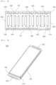
- FIG. 2 is a perspective view of a battery module according to a preferred embodiment of the present invention
- FIG. 3 is a front view of the battery module shown in FIG. 2
- FIG. 4 is a perspective view of a battery cell that is mounted in the battery module according to the preferred embodiment of the present invention.
- FIG. 5 is a perspective view of the battery module according to the preferred embodiment of the present invention in the state in which a module case is removed therefrom
- FIG. 6 is a perspective view of the battery module shown in FIG. 5 in the state in which some of battery cells, busbar frames, and busbars are separated therefrom.
- the battery module according to the present invention includes a module case 100, a plurality of battery cells 200, a plurality of busbars 300, a busbar frame 400, a shock absorption pad 500, and a heat dissipation pad 600.
- the module case 100 which protects the battery cells 200, the busbars 300, the busbar frame 400, the shock absorption pad 500, and the heat dissipation pad 600 from external shock while receiving the same, may have an approximately hexahedral shape.
- the module case may include a bottom plate 110 and a top plate 130 configured to support and protect lower parts and upper parts of the battery cells 200, respectively, and a pair of side plates 120 configured to support side surfaces of the battery cells.
- the bottom plate 110, the pair of side plates 120, and the top plate 130 may be integrally manufactured, or may be individually manufactured and connected to each other using known means, such as bolts. Although a front plate and a rear plate are not shown in the drawings, the front plate and the rear plate may be further provided as needed.
- the battery cells (200) received in the module case 100 are erected upright and stacked side by side.
- a battery cell 200 includes an upper cell case 210, a lower cell case 220, an electrode assembly (not shown) received in the upper and lower cell cases, a sealed portion 230 provided at edges of the upper and lower cell cases, a pair of electrode tabs (not shown), a pair of electrode leads constituted by a positive electrode lead 240 and a negative electrode lead 250 each having one side electrically connected to a corresponding one of the electrode tabs and the other side protruding outwards from the cell cases, and an insulative film (not shown).
- each of the upper cell case 210 and the lower cell case 220 is provided with a pocket-shaped space portion configured to receive the electrode assembly.
- the cell cases form a space portion capable of receiving the electrode assembly using a laminate sheet including an outer coating layer, a metal layer, and an inner coating layer.
- the inner coating layer is disposed in direct contact with the electrode assembly, and therefore the inner coating layer must exhibit high insulation properties and high resistance to an electrolytic solution.
- the inner coating layer must exhibit high sealability in order to hermetically seal the cell case from the outside, i.e., a thermally-bonded sealed portion between inner layers must exhibit excellent thermal bonding strength.
- the inner coating layer may be made of a material selected from among a polyolefin-based resin, such as polypropylene, polyethylene, polyethylene acrylate, or polybutylene, a polyurethane resin, and a polyimide resin, which exhibit excellent chemical resistance and high sealability.
- a polyolefin-based resin such as polypropylene, polyethylene, polyethylene acrylate, or polybutylene, a polyurethane resin, and a polyimide resin, which exhibit excellent chemical resistance and high sealability.
- polypropylene which exhibits excellent mechanical-physical properties, such as tensile strength, rigidity, surface hardness, and impact resistance, and excellent chemical resistance, is the most preferably used.
- the metal layer which is disposed so as to abut the inner coating layer, corresponds to a barrier layer configured to prevent moisture or various kinds of gas from permeating into the battery from outside.
- An aluminum thin film which is lightweight and easily shapeable, may be used as a preferred material for the metal layer.
- the outer coating layer is provided on the other surface of the metal layer.
- the outer coating layer may be made of a heat resistant polymer that exhibits excellent tensile strength, resistance to moisture permeation, and resistance to air transmission such that the outer coating layer exhibits high heat resistance and chemical resistance while protecting the electrode assembly.
- the outer coating layer may be made of nylon or polyethylene terephthalate.
- the present invention is not limited thereto.
- the electrode assembly received in the upper cell case 210 and the lower cell case 220 may be classified as a stacked type electrode assembly, configured to have a structure in which a plurality of electrodes is stacked, a jelly-roll type electrode assembly, configured to have a structure in which a positive electrode and a negative electrode are wound in the state in which a separator is interposed therebetween, a laminated and stacked type electrode assembly, configured to have a structure in which a plurality of unit cells is stacked, or a stacked and folded type electrode assembly, configured to have a structure in which a separator sheet is wound in the state in which unit cells are disposed on the separator sheet.
- a stacked type electrode assembly configured to have a structure in which a plurality of electrodes is stacked
- a jelly-roll type electrode assembly configured to have a structure in which a positive electrode and a negative electrode are wound in the state in which a separator is interposed therebetween
- a laminated and stacked type electrode assembly configured to have a structure in which
- a unit cell is manufactured in order to constitute the laminated and stacked type electrode assembly and the stacked and folded type electrode assembly.
- the unit cell may be a mono-cell, configured to have a structure in which a separator is interposed between a positive electrode and a negative electrode, or a bi-cell, configured to have a structure in which a positive electrode, a negative electrode, and a positive electrode or a negative electrode, a positive electrode, and a negative electrode are stacked in the state in which a separator is interposed between the positive electrode and the negative electrode.
- the electrode assembly according to the present invention may be configured to have a structure in which a negative electrode, a separator, a positive electrode, a separator, and a negative electrode are stacked, and the number of positive electrodes and negative electrodes constituting the electrode assembly may be freely set.
- a laminated and stacked type electrode assembly configured to have a structure in which a plurality of unit cells is laminated, may be used. The structure of the electrode assembly may be applied to all electrode assembles described in this specification.
- the positive electrode and the negative electrode of the electrode assembly are provided with a positive electrode tab and a negative electrode tab, respectively.
- the pair of tabs is disposed so as to protrude a predetermined length outwards from the cell case in a state of being connected respectively to a positive electrode lead 240 and a negative electrode lead 250 by spot welding.
- the insulative film is located at an upper surface and a lower surface of each of the pair of electrode leads, more specifically the sealed portion 230, at which the upper cell case 210 and the lower cell case 220 are thermally fused.
- the insulative film is preferably made of a nonconductive material that hardly transmits electricity.
- an insulative tape that has a relatively small thickness while being easily attached to each of the electrode leads is widely used; however, the present invention is not limited thereto.
- a bidirectional battery cell configured such that a positive electrode lead 240 and a negative electrode lead 250 are located so as to face each other is shown in the figure
- a unidirectional battery cell configured such that a pair of electrode leads is disposed so as to face in the same direction may be used.
- the busbar 300 is configured to connect the plurality of battery cells 200 received in the module case 100 to each other in series or in parallel.
- the busbar 300 is a conductor having low impedance and high current capacity.
- the plurality of busbars 300 is disposed side by side in a direction in which the plurality of battery cells 200 is stacked so as to connect the battery cells 200 to each other in series or in parallel.
- the busbar 300 according to the present invention is illustrated as being configured in a plate-shaped structure having a uniform thickness; however, the present invention is not limited thereto, and the busbar may be modified so as to have various structures in which electrical connection is possible.
- three busbars 300 are disposed at the front of the battery module to electrically connect the battery cells 200 to each other, and one of the busbars 300 is longer than the other busbars.
- the busbar 300 located at the right side, among the three busbars disposed side by side in a lateral direction of the module case 100 includes a busbar body 310 and an extension portion 320, wherein the extension portion 310 is located so as to protrude a predetermined length from a lower end of the busbar body 310 toward the bottom plate 110 of the module case 100.
- no extension portion is provided at each of the other two busbars 300.
- thermal-fusion sealed portions may be separated from each other due to repeated charging and discharging, i.e., a thermally fused portion may be deteriorated due to repetition of swelling pressure due to gas generated by an irreversible reaction or the environment in which high current is used, such as quick charging, whereby the electrolytic solution may leak.
- the electrolytic solution may leak due to various causes, such as tear of the case caused by external impact or chemical corrosion.
- the electrolytic solution gathers on the bottom of the module case.
- the size of the busbars mounted to the battery module or the distance of the busbars from the bottom of the module case are uniform.
- the plurality of busbars simultaneously contacts the electrolytic solution, whereby short circuit outside the cell occurs.
- the one of the busbars may sense an increase in level of the leaked electrolytic solution in advance, whereby it is possible to detect and prevent short circuit outside the cell in advance, and therefore it is possible to inhibit occurrence of abrupt fire outbreak.
- the busbar body 310 and the extension portion 320 constituting the busbar 300 may be integrated; however, it is more preferable for the busbar body and the extension portion to be separated from each other such that the distance from the bottom surface of the case is easily adjusted.
- the busbar body 310 and the extension portion 320 may be made of the same material, and the busbar body 310 and the extension portion 320 may be connected to each other using a known fixing means, such as welding, a bolt, or a thermally conductive adhesive.
- busbars may be located at the rear of the battery module, and any one of the busbars may extend a predetermined length toward the bottom surface of the case.
- the busbar frame 400 is fixed to the module case 100 in a state of supporting the busbar 300. Specifically, the leads of the battery cells 200 are bent after extending through slits of the busbar 300, and are then fixed to the busbar 300 through a known fixing means, such as laser welding or resistance welding. In order to stably support the battery cells 200 and the busbar 300, the busbar frame 400 is located between the battery cells 200 and the busbar 300.
- busbar frames 400 are shown as being mounted in the drawings, this is merely one illustration, and one busbar frame or four or more busbar frames may be provided.
- the shock absorption pad 500 is interposed between an inner surface of the side plate 120 of the module case 100 and the battery cell 200.
- the shock absorption pad 500 is configured to press the battery cell 200 when the battery cell swells.
- the shock absorption pad 500 is made of elastomer or foam, such as polyurethane foam; however, the present invention is not limited thereto.
- the heat dissipation pad 600 may be further provided between an upper surface of the bottom plate 110 of the module case 100 and the battery cell 200.
- the heat dissipation pad 600 which discharges heat generated in the battery cell 200 to the outside and fixes the battery cells 200, to be made of a thermal interface material (TIM).
- TIM thermal interface material
- the method of manufacturing the battery module according to the present invention includes a step of preparing a module case 100, a plurality of battery cells 200, and a plurality of busbars 300 and a step of receiving the plurality of battery cells 100 in the module case 100 and electrically connecting the plurality of battery cells 100 to each other through the plurality of busbars 200.
- At least one busbar 300 among the plurality of busbars 300, to have an extension portion 320 protruding from a lower end of a busbar body 310 by a predetermined length toward a bottom plate 110 of the module case 100.
- the battery module described above may constitute a battery pack, and may be applied to various devices.
Landscapes
- Chemical & Material Sciences (AREA)
- Chemical Kinetics & Catalysis (AREA)
- Electrochemistry (AREA)
- General Chemical & Material Sciences (AREA)
- Engineering & Computer Science (AREA)
- Manufacturing & Machinery (AREA)
- Inorganic Chemistry (AREA)
- Connection Of Batteries Or Terminals (AREA)
- Battery Mounting, Suspending (AREA)
Abstract
The present invention relates to a battery module having an electrolytic solution leakage detection function and a battery pack including the same, and more particularly to a battery module having a busbar configured to detect an electrolytic solution leaked from a battery cell and a battery pack including the same.
Description
- This application claims the benefit of priority to
Korean Patent Application No. 2021-0181419 filed on December 17, 2021 - The present invention relates to a battery module having an electrolytic solution leakage detection function and a battery pack including the same, and more particularly to a battery module having an electrolytic solution leakage detection function configured such that the length of any one busbar is changed to sense an increase in level of an electrolytic solution when the electrolytic solution leaks in the battery module, thereby preventing fire outbreak due to short circuit outside a cell, and a battery pack including the same.
- With technological development of mobile devices, such as smartphones, laptop computers, and digital cameras, and an increase in demand therefor, research on secondary batteries, which are capable of being charged and discharged, has been actively conducted. In addition, secondary batteries, which are energy sources substituting for fossil fuels causing air pollution, have been applied to an electric vehicle (EV), a hybrid electric vehicle (HEV), a plug-in hybrid electric vehicle (P-HEV), and an energy storage system (ESS).
- There are a lithium ion battery, a lithium polymer battery, a nickel-cadmium battery, a nickel-hydride battery, and a nickel-zinc battery as secondary batteries that are widely used at present. For such a unit secondary battery cell, a plurality of battery cells is generally connected to each other in series or in parallel to constitute a battery module depending on required output voltage or charge and discharge capacities.
- In particular, usage of a pouch-shaped lithium ion battery, configured to have a structure in which a stacked type or stacked and folded type electrode assembly is mounted in a pouch-shaped battery case made of an aluminum laminate sheet, has gradually increased due to advantages of low manufacturing cost and high energy density.
- However, the pouch-shaped lithium ion battery has a problem in that, when thermally fused sealed portions are separated from each other, a flammable material, such as an electrolytic solution, leaks, whereby there is a danger of fire outbreak.
-
FIG. 1 is a conceptual view for sensing whether an electrolytic solution leaks in accordance with the conventional art. According to the conventional art ofFIG. 1 , an electrolyticsolution absorption member 10 attached to the outside of a cell to absorb an electrolytic solution that leaks from the cell, the electrolytic solution absorption member having the characteristics of a conductor as the result of absorbing the electrolytic solution, a power supply unit 20 connected to opposite ends of the electrolytic solution absorption member to apply power to the electrolytic solution absorption member, aresistance unit 30 connected between the electrolytic solution absorption member and the power supply unit, asensing unit 40 configured to sense whether current flows in the resistance unit, and acontroller 50 configured to cut a fuse on a charging and discharging path of a battery pack by fusion in order to block charging and discharging current when the sensing unit sense that current flows in the resistance unit are included. - The conventional art has an advantage in that the leaked electrolytic solution is detected, whereby it is possible to protect a battery module or the battery pack; however, the overall structure is very complicated since the electrolytic solution is absorbed and whether current flows is sensed. Furthermore, a plurality of members must be additionally provided, whereby energy density is lowered.
- (Patent Document 1)
Korean Registered Patent Publication No. 1383599 - The present invention has been made in view of the above problems, and it is an object of the present invention to provide a battery module having an electrolytic solution leakage detection function capable of rapidly detecting whether an electrolytic solution leaks through a simple structure and a battery pack including the same.
- It is another object of the present invention to provide a battery module having an electrolytic solution leakage detection function capable of checking whether an electrolytic solution leaks without an increase in volume and a battery pack including the same.
- A battery module according to the present invention to accomplish the above objects has a busbar (300) configured to detect an electrolytic solution leaked from a battery cell.
- In addition, the battery module according to the present invention may include a module case (100) including a bottom plate (110), a side plate (120), and a top plate (130); a plurality of battery cells (200) received in the module case (100); and a plurality of busbars (300) configured to connect the plurality of battery cells (200) to each other in series or in parallel, and at least one of the plurality of busbars (300) may include an extension portion (320) protruding from a lower end of a busbar body (310) by a predetermined length toward the bottom plate (110) of the module case (100).
- Also, in the battery module according to the present invention, a bottom edge of the extension portion (320) of the busbar (300) may be spaced apart from an upper surface of the bottom plate (110) of the module case (100) by a predetermined distance.
- Also, in the battery module according to the present invention, the busbar body (310) and the extension portion (320) may be integrally formed.
- Also, in the battery module according to the present invention, the busbar body (310) and the extension portion (320) may be separated from each other and may be electrically connected to each other by a connection member.
- Also, in the battery module according to the present invention, the connection member may be welding or a thermally conductive adhesive.
- In addition, the battery module according to the present invention may further include a shock absorption pad (500) provided between an inner surface of the side plate (120) of the module case (100) and the plurality of battery cells (200).
- In addition, the battery module according to the present invention may further include a heat dissipation pad (600) provided between an upper surface of the bottom plate (110) of the module case (100) and the plurality of battery cells (200).
- In addition, the battery module according to the present invention may further include a busbar frame (400) interposed between the plurality of battery cells (200) and the plurality of busbars (300).
- Also, in the battery module according to the present invention, each of the plurality of battery cells (200) may be a pouch-shaped battery cell.
- In addition, a method of manufacturing a battery module according to the present invention includes a first step of preparing a module case (100), a plurality of battery cells (200), and a plurality of busbars (300) and a second step of receiving the plurality of battery cells (100) in the module case (100) and electrically connecting the plurality of battery cells (100) to each other through the plurality of busbars (200), wherein at least one of the plurality of busbars (300) includes an extension portion (320) protruding from a lower end of a busbar body (310) by a predetermined length toward a bottom plate (110) of the module case (100).
- In addition, the present invention provides a battery pack including the battery module.
- A battery module having an electrolytic solution leakage detection function according to the present invention and a battery pack including the same have an advantage in that an extension portion facing the bottom of a module case is provided at a lower end of any one busbar, whereby it is possible to rapidly detect whether an electrolytic solution leaks.
- In addition, the battery module having the electrolytic solution leakage detection function according to the present invention and the battery pack including the same have a merit in that a sensor configured to detect the electrolytic solution or a separate controller is not necessary, whereby it is possible to prevent a decrease in energy density.
- Furthermore, the battery module having the electrolytic solution leakage detection function according to the present invention and the battery pack including the same have an advantage in that, when the level of the leaked electrolytic solution is increased, one busbar may sense the same in advance, whereby it is possible to detect and prevent short circuit outside a cell in advance, and therefore it is possible to inhibit occurrence of abrupt fire outbreak.
-
-
FIG. 1 is a conceptual view for sensing whether an electrolytic solution leaks in accordance with the conventional art. -
FIG. 2 is a perspective view of a battery module according to a preferred embodiment of the present invention. -
FIG. 3 is a front view of the battery module shown inFIG. 2 . -
FIG. 4 is a perspective view of a battery cell that is mounted in the battery module according to the preferred embodiment of the present invention. -
FIG. 5 is a perspective view of the battery module according to the preferred embodiment of the present invention in the state in which a module case is removed therefrom. -
FIG. 6 is a perspective view of the battery module shown inFIG. 5 in the state in which some of battery cells, busbar frames, and busbars are separated therefrom. - In the present application, it should be understood that the terms "comprises," "has," "includes," etc. specify the presence of stated features, numbers, steps, operations, elements, components, or combinations thereof, but do not preclude the presence or addition of one or more other features, numbers, steps, operations, elements, components, or combinations thereof.
- In addition, the same reference numbers will be used throughout the drawings to refer to parts that perform similar functions or operations. In the case in which one part is said to be connected to another part in the specification, not only may the one part be directly connected to the other part, but also, the one part may be indirectly connected to the other part via a further part. In addition, that a certain element is included does not mean that other elements are excluded, but means that such elements may be further included unless mentioned otherwise.
- Hereinafter, a battery module having an electrolytic solution leakage detection function according to the present invention will be described.
-
FIG. 2 is a perspective view of a battery module according to a preferred embodiment of the present invention,FIG. 3 is a front view of the battery module shown inFIG. 2 , andFIG. 4 is a perspective view of a battery cell that is mounted in the battery module according to the preferred embodiment of the present invention. - In addition,
FIG. 5 is a perspective view of the battery module according to the preferred embodiment of the present invention in the state in which a module case is removed therefrom, andFIG. 6 is a perspective view of the battery module shown inFIG. 5 in the state in which some of battery cells, busbar frames, and busbars are separated therefrom. - Referring to
FIGS. 2 to 6 , the battery module according to the present invention includes amodule case 100, a plurality ofbattery cells 200, a plurality ofbusbars 300, abusbar frame 400, ashock absorption pad 500, and aheat dissipation pad 600. - The
module case 100, which protects thebattery cells 200, thebusbars 300, thebusbar frame 400, theshock absorption pad 500, and theheat dissipation pad 600 from external shock while receiving the same, may have an approximately hexahedral shape. - Specifically, the module case may include a
bottom plate 110 and atop plate 130 configured to support and protect lower parts and upper parts of thebattery cells 200, respectively, and a pair ofside plates 120 configured to support side surfaces of the battery cells. - The
bottom plate 110, the pair ofside plates 120, and thetop plate 130 may be integrally manufactured, or may be individually manufactured and connected to each other using known means, such as bolts. Although a front plate and a rear plate are not shown in the drawings, the front plate and the rear plate may be further provided as needed. - The battery cells (200) received in the
module case 100, more specifically pouch-shaped battery cells, are erected upright and stacked side by side. - As an example, as shown in
FIG. 4 , abattery cell 200 includes anupper cell case 210, alower cell case 220, an electrode assembly (not shown) received in the upper and lower cell cases, a sealedportion 230 provided at edges of the upper and lower cell cases, a pair of electrode tabs (not shown), a pair of electrode leads constituted by apositive electrode lead 240 and anegative electrode lead 250 each having one side electrically connected to a corresponding one of the electrode tabs and the other side protruding outwards from the cell cases, and an insulative film (not shown). - Specifically, each of the
upper cell case 210 and thelower cell case 220 is provided with a pocket-shaped space portion configured to receive the electrode assembly. - The cell cases form a space portion capable of receiving the electrode assembly using a laminate sheet including an outer coating layer, a metal layer, and an inner coating layer.
- The inner coating layer is disposed in direct contact with the electrode assembly, and therefore the inner coating layer must exhibit high insulation properties and high resistance to an electrolytic solution. In addition, the inner coating layer must exhibit high sealability in order to hermetically seal the cell case from the outside, i.e., a thermally-bonded sealed portion between inner layers must exhibit excellent thermal bonding strength.
- The inner coating layer may be made of a material selected from among a polyolefin-based resin, such as polypropylene, polyethylene, polyethylene acrylate, or polybutylene, a polyurethane resin, and a polyimide resin, which exhibit excellent chemical resistance and high sealability. However, the present invention is not limited thereto, and polypropylene, which exhibits excellent mechanical-physical properties, such as tensile strength, rigidity, surface hardness, and impact resistance, and excellent chemical resistance, is the most preferably used.
- The metal layer, which is disposed so as to abut the inner coating layer, corresponds to a barrier layer configured to prevent moisture or various kinds of gas from permeating into the battery from outside. An aluminum thin film, which is lightweight and easily shapeable, may be used as a preferred material for the metal layer.
- The outer coating layer is provided on the other surface of the metal layer. The outer coating layer may be made of a heat resistant polymer that exhibits excellent tensile strength, resistance to moisture permeation, and resistance to air transmission such that the outer coating layer exhibits high heat resistance and chemical resistance while protecting the electrode assembly. As an example, the outer coating layer may be made of nylon or polyethylene terephthalate. However, the present invention is not limited thereto.
- Meanwhile, the electrode assembly received in the
upper cell case 210 and thelower cell case 220 may be classified as a stacked type electrode assembly, configured to have a structure in which a plurality of electrodes is stacked, a jelly-roll type electrode assembly, configured to have a structure in which a positive electrode and a negative electrode are wound in the state in which a separator is interposed therebetween, a laminated and stacked type electrode assembly, configured to have a structure in which a plurality of unit cells is stacked, or a stacked and folded type electrode assembly, configured to have a structure in which a separator sheet is wound in the state in which unit cells are disposed on the separator sheet. - A unit cell is manufactured in order to constitute the laminated and stacked type electrode assembly and the stacked and folded type electrode assembly. The unit cell may be a mono-cell, configured to have a structure in which a separator is interposed between a positive electrode and a negative electrode, or a bi-cell, configured to have a structure in which a positive electrode, a negative electrode, and a positive electrode or a negative electrode, a positive electrode, and a negative electrode are stacked in the state in which a separator is interposed between the positive electrode and the negative electrode.
- The electrode assembly according to the present invention may be configured to have a structure in which a negative electrode, a separator, a positive electrode, a separator, and a negative electrode are stacked, and the number of positive electrodes and negative electrodes constituting the electrode assembly may be freely set. In addition, a laminated and stacked type electrode assembly, configured to have a structure in which a plurality of unit cells is laminated, may be used. The structure of the electrode assembly may be applied to all electrode assembles described in this specification.
- The positive electrode and the negative electrode of the electrode assembly are provided with a positive electrode tab and a negative electrode tab, respectively. The pair of tabs is disposed so as to protrude a predetermined length outwards from the cell case in a state of being connected respectively to a
positive electrode lead 240 and anegative electrode lead 250 by spot welding. - The insulative film is located at an upper surface and a lower surface of each of the pair of electrode leads, more specifically the sealed
portion 230, at which theupper cell case 210 and thelower cell case 220 are thermally fused. - Consequently, the flow of electricity generated from the electrode assembly to the cell case through the electrode leads is prevented, and sealing between the electrode leads and the cell cases is maintained. Here, the insulative film is preferably made of a nonconductive material that hardly transmits electricity. In general, an insulative tape that has a relatively small thickness while being easily attached to each of the electrode leads is widely used; however, the present invention is not limited thereto.
- Although a bidirectional battery cell configured such that a
positive electrode lead 240 and anegative electrode lead 250 are located so as to face each other is shown in the figure, a unidirectional battery cell configured such that a pair of electrode leads is disposed so as to face in the same direction may be used. - Next, the busbar will be described. The
busbar 300 is configured to connect the plurality ofbattery cells 200 received in themodule case 100 to each other in series or in parallel. - That is, the
busbar 300 is a conductor having low impedance and high current capacity. The plurality ofbusbars 300 is disposed side by side in a direction in which the plurality ofbattery cells 200 is stacked so as to connect thebattery cells 200 to each other in series or in parallel. - The
busbar 300 according to the present invention is illustrated as being configured in a plate-shaped structure having a uniform thickness; however, the present invention is not limited thereto, and the busbar may be modified so as to have various structures in which electrical connection is possible. - Meanwhile, in the battery module according to the present invention, three
busbars 300 are disposed at the front of the battery module to electrically connect thebattery cells 200 to each other, and one of thebusbars 300 is longer than the other busbars. - Specifically, referring to
FIGS. 2 ,3 , and5 , thebusbar 300 located at the right side, among the three busbars disposed side by side in a lateral direction of themodule case 100, includes abusbar body 310 and anextension portion 320, wherein theextension portion 310 is located so as to protrude a predetermined length from a lower end of thebusbar body 310 toward thebottom plate 110 of themodule case 100. On the other hand, no extension portion is provided at each of the other twobusbars 300. - During use of the battery module, thermal-fusion sealed portions may be separated from each other due to repeated charging and discharging, i.e., a thermally fused portion may be deteriorated due to repetition of swelling pressure due to gas generated by an irreversible reaction or the environment in which high current is used, such as quick charging, whereby the electrolytic solution may leak.
- Of course, the electrolytic solution may leak due to various causes, such as tear of the case caused by external impact or chemical corrosion.
- The electrolytic solution gathers on the bottom of the module case. In general, the size of the busbars mounted to the battery module or the distance of the busbars from the bottom of the module case are uniform. As a result, the plurality of busbars simultaneously contacts the electrolytic solution, whereby short circuit outside the cell occurs.
- When the extension portion is formed at any one of the busbars and is disposed so as to face the bottom of the module case, as in the present invention, however, the one of the busbars may sense an increase in level of the leaked electrolytic solution in advance, whereby it is possible to detect and prevent short circuit outside the cell in advance, and therefore it is possible to inhibit occurrence of abrupt fire outbreak.
- Here, the
busbar body 310 and theextension portion 320 constituting thebusbar 300 may be integrated; however, it is more preferable for the busbar body and the extension portion to be separated from each other such that the distance from the bottom surface of the case is easily adjusted. In this case, thebusbar body 310 and theextension portion 320 may be made of the same material, and thebusbar body 310 and theextension portion 320 may be connected to each other using a known fixing means, such as welding, a bolt, or a thermally conductive adhesive. - In the above, a description was given based on the front of the battery module. However, the same number of busbars may be located at the rear of the battery module, and any one of the busbars may extend a predetermined length toward the bottom surface of the case.
- The
busbar frame 400 is fixed to themodule case 100 in a state of supporting thebusbar 300. Specifically, the leads of thebattery cells 200 are bent after extending through slits of thebusbar 300, and are then fixed to thebusbar 300 through a known fixing means, such as laser welding or resistance welding. In order to stably support thebattery cells 200 and thebusbar 300, thebusbar frame 400 is located between thebattery cells 200 and thebusbar 300. - Although three
busbar frames 400 are shown as being mounted in the drawings, this is merely one illustration, and one busbar frame or four or more busbar frames may be provided. - Next, the shock absorption pad will be described. The
shock absorption pad 500 is interposed between an inner surface of theside plate 120 of themodule case 100 and thebattery cell 200. Theshock absorption pad 500 is configured to press thebattery cell 200 when the battery cell swells. - The
shock absorption pad 500 is made of elastomer or foam, such as polyurethane foam; however, the present invention is not limited thereto. - Meanwhile, the
heat dissipation pad 600 may be further provided between an upper surface of thebottom plate 110 of themodule case 100 and thebattery cell 200. - It is preferable for the
heat dissipation pad 600, which discharges heat generated in thebattery cell 200 to the outside and fixes thebattery cells 200, to be made of a thermal interface material (TIM). - Next, a method of manufacturing a battery module according to an embodiment of the present invention will be described.
- The method of manufacturing the battery module according to the present invention includes a step of preparing a
module case 100, a plurality ofbattery cells 200, and a plurality ofbusbars 300 and a step of receiving the plurality ofbattery cells 100 in themodule case 100 and electrically connecting the plurality ofbattery cells 100 to each other through the plurality ofbusbars 200. - Here, it is preferable for at least one
busbar 300, among the plurality ofbusbars 300, to have anextension portion 320 protruding from a lower end of abusbar body 310 by a predetermined length toward abottom plate 110 of themodule case 100. - The battery module described above may constitute a battery pack, and may be applied to various devices.
- Although the specific details of the present invention have been described in detail, those skilled in the art will appreciate that the detailed description thereof discloses only preferred embodiments of the present invention and thus does not limit the scope of the present invention. Accordingly, those skilled in the art will appreciate that various changes and modifications are possible, without departing from the category and technical idea of the present invention, and it will be obvious that such changes and modifications fall within the scope of the appended claims.
-
- 100:
- Module case
- 110:
- Bottom plate
- 120:
- Side plate
- 130:
- Top plate
- 200:
- Battery cell
- 210:
- Upper cell case
- 220:
- Lower cell case
- 230:
- Sealed portion
- 240:
- Positive electrode lead
- 250:
- Negative electrode lead
- 300:
- Busbar
- 310:
- Busbar body
- 320:
- Extension portion
- 400:
- Busbar frame
- 500:
- Shock absorption pad
- 600:
- Heat dissipation pad
Claims (12)
- A battery module having a busbar configured to detect an electrolytic solution leaked from a battery cell.
- The battery module according to claim 1, wherein the battery module comprises:a module case comprising a bottom plate, a side plate, and a top plate;a plurality of battery cells received in the module case; anda plurality of busbars configured to connect the plurality of battery cells to each other in series or in parallel, andwherein at least one of the plurality of busbars includes an extension portion protruding from a lower end of a busbar body by a predetermined length toward the bottom plate of the module case.
- The battery module according to claim 2, wherein a bottom edge of the extension portion of the busbar is spaced apart from an upper surface of the bottom plate of the module case by a predetermined distance.
- The battery module according to claim 3, wherein the busbar body and the extension portion are integrally formed.
- The battery module according to claim 3, wherein the busbar body and the extension portion are separated from each other and are electrically connected to each other by a connection member.
- The battery module according to claim 5, wherein the connection member is welding or a thermally conductive adhesive.
- The battery module according to claim 2, further comprising a shock absorption pad provided between an inner surface of the side plate of the module case and the plurality of battery cells.
- The battery module according to claim 2, further comprising a heat dissipation pad provided between an upper surface of the bottom plate of the module case and the plurality of battery cells.
- The battery module according to claim 2, further comprising a busbar frame interposed between the plurality of battery cells and the plurality of busbars.
- The battery module according to claim 2, wherein each of the plurality of battery cells is a pouch-shaped battery cell.
- A battery pack comprising the battery module according to any one of claims 1 to 10.
- A method of manufacturing the battery module according to any one of claims 1 to 10, the method comprising:preparing a module case, a plurality of battery cells, and a plurality of busbars; andreceiving the plurality of battery cells in the module case and electrically connecting the plurality of battery cells to each other through the plurality of busbars, whereinat least one of the plurality of busbars includes an extension portion protruding from a lower end of a busbar body by a predetermined length toward a bottom plate of the module case.
Applications Claiming Priority (2)
| Application Number | Priority Date | Filing Date | Title |
|---|---|---|---|
| KR1020210181419A KR20230092218A (en) | 2021-12-17 | 2021-12-17 | Battery module with electrolyte leakage detection function and battery pack comprising the same |
| PCT/KR2022/008838 WO2023113122A1 (en) | 2021-12-17 | 2022-06-22 | Battery module having function of detecting electrolyte leakage, and battery pack comprising same |
Publications (1)
| Publication Number | Publication Date |
|---|---|
| EP4224596A1 true EP4224596A1 (en) | 2023-08-09 |
Family
ID=85227305
Family Applications (1)
| Application Number | Title | Priority Date | Filing Date |
|---|---|---|---|
| EP22835541.8A Pending EP4224596A1 (en) | 2021-12-17 | 2022-06-22 | Battery module having function of detecting electrolyte leakage, and battery pack comprising same |
Country Status (6)
| Country | Link |
|---|---|
| US (1) | US20240021888A1 (en) |
| EP (1) | EP4224596A1 (en) |
| JP (1) | JP2024504223A (en) |
| KR (1) | KR20230092218A (en) |
| CN (1) | CN116615837A (en) |
| WO (1) | WO2023113122A1 (en) |
Family Cites Families (6)
| Publication number | Priority date | Publication date | Assignee | Title |
|---|---|---|---|---|
| JP4810745B2 (en) * | 2000-12-21 | 2011-11-09 | ソニー株式会社 | Battery pack with electrolyte leakage detection function |
| KR101383599B1 (en) | 2009-11-13 | 2014-04-10 | 주식회사 엘지화학 | Apparatus and method for protecting battery pack by detecting electrolyte leakage |
| JP2017098011A (en) * | 2015-11-20 | 2017-06-01 | トヨタ自動車株式会社 | Battery module for vehicle |
| JP7047548B2 (en) * | 2018-04-02 | 2022-04-05 | 日産自動車株式会社 | Rechargeable battery system |
| JP7054110B2 (en) * | 2018-10-29 | 2022-04-13 | 国立研究開発法人産業技術総合研究所 | Leak inspection device and leak inspection system |
| KR20210024917A (en) * | 2019-08-26 | 2021-03-08 | 주식회사 엘지화학 | Detection device for electrolyte and moving device of secondary battery including the same |
-
2021
- 2021-12-17 KR KR1020210181419A patent/KR20230092218A/en active Search and Examination
-
2022
- 2022-06-22 JP JP2023515823A patent/JP2024504223A/en active Pending
- 2022-06-22 CN CN202280004895.9A patent/CN116615837A/en active Pending
- 2022-06-22 WO PCT/KR2022/008838 patent/WO2023113122A1/en active Application Filing
- 2022-06-22 EP EP22835541.8A patent/EP4224596A1/en active Pending
-
2023
- 2023-03-30 US US18/128,631 patent/US20240021888A1/en active Pending
Also Published As
| Publication number | Publication date |
|---|---|
| US20240021888A1 (en) | 2024-01-18 |
| WO2023113122A1 (en) | 2023-06-22 |
| CN116615837A (en) | 2023-08-18 |
| KR20230092218A (en) | 2023-06-26 |
| JP2024504223A (en) | 2024-01-31 |
Similar Documents
| Publication | Publication Date | Title |
|---|---|---|
| US9653724B2 (en) | Secondary battery, and secondary battery module and secondary battery pack comprising the same | |
| CN107949932B (en) | Battery cell having venting structure using adhesive tape | |
| KR101252981B1 (en) | Pouch of improved safety for secondary battery and secondary battery, battery pack using the same | |
| KR20190028200A (en) | Battery module with a structure to break a connector using venting gas | |
| KR102335202B1 (en) | Secondary Battery with improved Stability having Heat Expandable layer and Method thereof | |
| EP3598532A1 (en) | Battery module provided with connector breaking device | |
| KR101367751B1 (en) | secondary battery and manufacturing method thereof | |
| EP4131584A1 (en) | Battery module comprising heat insulating member | |
| US9240618B2 (en) | Rechargeable battery and battery module | |
| KR20140094205A (en) | Rechargeable battery | |
| US11158901B2 (en) | Lithium secondary battery pack including thermal expansion tape fixing pouch type battery cells and method of manufacturing same | |
| CN114930621A (en) | Pouch type secondary battery and battery module including the same | |
| EP4224596A1 (en) | Battery module having function of detecting electrolyte leakage, and battery pack comprising same | |
| KR20220046135A (en) | Pouch type secondary battery and battery module including the same | |
| KR102364930B1 (en) | Battery Pack Comprising coverlay | |
| KR20220005221A (en) | Battery Module With Electrode Lead And Busbar Connected By Adhesive Member | |
| KR20210109824A (en) | Battery module with busbar frame for preventing spring back of cell lead and battery pack including the same | |
| EP4429014A1 (en) | Electrolyte leakage detection unit using insulation resistance, and battery module comprising same | |
| KR20200084403A (en) | Battery module for electric vehicles and control methode thereof | |
| KR20200104614A (en) | Battery pack having bending shaped sensing bus bar and device including the same | |
| EP4243194A1 (en) | Pouch-type battery cell with improved thermal stability | |
| US20220263204A1 (en) | Battery Cell, Battery Module And Vehicle | |
| EP4250449A1 (en) | Pouch-type battery cell having improved safety, and battery module comprising same | |
| US20230411810A1 (en) | Pouch-Shaped Battery Cell Having Safety Element Provided Between Electrode Lead and Lead Film | |
| US20240006706A1 (en) | Battery module for preventing thermal runaway propagation |
Legal Events
| Date | Code | Title | Description |
|---|---|---|---|
| STAA | Information on the status of an ep patent application or granted ep patent |
Free format text: STATUS: UNKNOWN |
|
| STAA | Information on the status of an ep patent application or granted ep patent |
Free format text: STATUS: THE INTERNATIONAL PUBLICATION HAS BEEN MADE |
|
| PUAI | Public reference made under article 153(3) epc to a published international application that has entered the european phase |
Free format text: ORIGINAL CODE: 0009012 |
|
| STAA | Information on the status of an ep patent application or granted ep patent |
Free format text: STATUS: REQUEST FOR EXAMINATION WAS MADE |
|
| 17P | Request for examination filed |
Effective date: 20230112 |
|
| AK | Designated contracting states |
Kind code of ref document: A1 Designated state(s): AL AT BE BG CH CY CZ DE DK EE ES FI FR GB GR HR HU IE IS IT LI LT LU LV MC MK MT NL NO PL PT RO RS SE SI SK SM TR |