EP4224189B1 - Lagebestimmung einer vorrichtung in einem mrt-system - Google Patents
Lagebestimmung einer vorrichtung in einem mrt-system Download PDFInfo
- Publication number
- EP4224189B1 EP4224189B1 EP22154982.7A EP22154982A EP4224189B1 EP 4224189 B1 EP4224189 B1 EP 4224189B1 EP 22154982 A EP22154982 A EP 22154982A EP 4224189 B1 EP4224189 B1 EP 4224189B1
- Authority
- EP
- European Patent Office
- Prior art keywords
- conductor loop
- imaging volume
- magnetic field
- loop
- measured value
- Prior art date
- Legal status (The legal status is an assumption and is not a legal conclusion. Google has not performed a legal analysis and makes no representation as to the accuracy of the status listed.)
- Active
Links
Images



Classifications
-
- G—PHYSICS
- G01—MEASURING; TESTING
- G01R—MEASURING ELECTRIC VARIABLES; MEASURING MAGNETIC VARIABLES
- G01R33/00—Arrangements or instruments for measuring magnetic variables
- G01R33/20—Arrangements or instruments for measuring magnetic variables involving magnetic resonance
- G01R33/28—Details of apparatus provided for in groups G01R33/44 - G01R33/64
- G01R33/285—Invasive instruments, e.g. catheters or biopsy needles, specially adapted for tracking, guiding or visualization by NMR
-
- A—HUMAN NECESSITIES
- A61—MEDICAL OR VETERINARY SCIENCE; HYGIENE
- A61B—DIAGNOSIS; SURGERY; IDENTIFICATION
- A61B5/00—Measuring for diagnostic purposes; Identification of persons
- A61B5/05—Detecting, measuring or recording for diagnosis by means of electric currents or magnetic fields; Measuring using microwaves or radio waves
- A61B5/055—Detecting, measuring or recording for diagnosis by means of electric currents or magnetic fields; Measuring using microwaves or radio waves involving electronic [EMR] or nuclear [NMR] magnetic resonance, e.g. magnetic resonance imaging
-
- A—HUMAN NECESSITIES
- A61—MEDICAL OR VETERINARY SCIENCE; HYGIENE
- A61B—DIAGNOSIS; SURGERY; IDENTIFICATION
- A61B5/00—Measuring for diagnostic purposes; Identification of persons
- A61B5/68—Arrangements of detecting, measuring or recording means, e.g. sensors, in relation to patient
-
- G—PHYSICS
- G01—MEASURING; TESTING
- G01R—MEASURING ELECTRIC VARIABLES; MEASURING MAGNETIC VARIABLES
- G01R33/00—Arrangements or instruments for measuring magnetic variables
- G01R33/20—Arrangements or instruments for measuring magnetic variables involving magnetic resonance
- G01R33/28—Details of apparatus provided for in groups G01R33/44 - G01R33/64
- G01R33/32—Excitation or detection systems, e.g. using radio frequency signals
- G01R33/34—Constructional details, e.g. resonators, specially adapted to MR
- G01R33/341—Constructional details, e.g. resonators, specially adapted to MR comprising surface coils
- G01R33/3415—Constructional details, e.g. resonators, specially adapted to MR comprising surface coils comprising arrays of sub-coils, i.e. phased-array coils with flexible receiver channels
-
- G—PHYSICS
- G01—MEASURING; TESTING
- G01R—MEASURING ELECTRIC VARIABLES; MEASURING MAGNETIC VARIABLES
- G01R33/00—Arrangements or instruments for measuring magnetic variables
- G01R33/20—Arrangements or instruments for measuring magnetic variables involving magnetic resonance
- G01R33/28—Details of apparatus provided for in groups G01R33/44 - G01R33/64
- G01R33/32—Excitation or detection systems, e.g. using radio frequency signals
- G01R33/36—Electrical details, e.g. matching or coupling of the coil to the receiver
- G01R33/3628—Tuning/matching of the transmit/receive coil
- G01R33/3635—Multi-frequency operation
-
- G—PHYSICS
- G01—MEASURING; TESTING
- G01R—MEASURING ELECTRIC VARIABLES; MEASURING MAGNETIC VARIABLES
- G01R33/00—Arrangements or instruments for measuring magnetic variables
- G01R33/20—Arrangements or instruments for measuring magnetic variables involving magnetic resonance
- G01R33/28—Details of apparatus provided for in groups G01R33/44 - G01R33/64
- G01R33/38—Systems for generation, homogenisation or stabilisation of the main or gradient magnetic field
- G01R33/387—Compensation of inhomogeneities
- G01R33/3875—Compensation of inhomogeneities using correction coil assemblies, e.g. active shimming
-
- G—PHYSICS
- G06—COMPUTING OR CALCULATING; COUNTING
- G06T—IMAGE DATA PROCESSING OR GENERATION, IN GENERAL
- G06T12/00—Tomographic reconstruction from projections
-
- G—PHYSICS
- G01—MEASURING; TESTING
- G01R—MEASURING ELECTRIC VARIABLES; MEASURING MAGNETIC VARIABLES
- G01R33/00—Arrangements or instruments for measuring magnetic variables
- G01R33/20—Arrangements or instruments for measuring magnetic variables involving magnetic resonance
- G01R33/28—Details of apparatus provided for in groups G01R33/44 - G01R33/64
- G01R33/32—Excitation or detection systems, e.g. using radio frequency signals
- G01R33/34—Constructional details, e.g. resonators, specially adapted to MR
- G01R33/34084—Constructional details, e.g. resonators, specially adapted to MR implantable coils or coils being geometrically adaptable to the sample, e.g. flexible coils or coils comprising mutually movable parts
Definitions
- Magnetic resonance imaging (MRI) systems are imaging devices that use a strong external magnetic field to align the nuclear spins of an object under examination and, by applying an RF excitation pulse, excite them to precess around the corresponding alignment.
- the precession, or transition of the spins from this excited state to a lower-energy state generates an alternating electromagnetic field in response, which can be detected as an MR signal via receiving antennas.
- a position coding can be applied to the signals, which then allows the received signal to be assigned to a volume element of the object under examination.
- the received signal can then be evaluated, for example, to provide an image representation of the object under examination.
- the patient's position in the imaging volume can be determined, for example, by visual Markers or the like are defined or determined, so it is desirable to determine the position of the device as accurately as possible.
- the device can, for example, be local MR receiver coils placed directly on the patient, such as head coils, knee coils, and so on. However, it can also be a device for medically treating the patient, such as a catheter, a surgical instrument, a biopsy needle, a robotic arm, and so on.
- Patient movement during an MRI examination is a well-known problem, especially for MRI examinations that take longer.
- Patient movement can alter the measured signals and cause image artifacts that can obscure or hinder the recognition of key features, particularly the radiological findings. Determining the position of the device is particularly advantageous in this context.
- a method and device are known for determining the location and orientation of an object, such as a medical instrument, inside or outside a body while the body is being scanned by a magnetic resonance imaging scanner.
- the method and device make it possible to determine the position of various devices, such as catheters, surgical instruments, biopsy needles, etc., by detecting voltages induced by time-varying magnetic fields in a set of miniature coils. Such time-varying fields are generated by the magnetic resonance imaging scanner during normal operation.
- the relative position of the at least one first conductor loop to the at least one second conductor loop can be known or fixedly predetermined.
- the position of the at least one first conductor loop and the position of the at least one second conductor loop can be determined as described.
- the predetermined or known relative positions to one another thus allow the position of the device to be determined more precisely or restricted more strongly.
- the filter circuit can be configured, for example, as a low-pass filter or a band-pass filter.
- the filter circuit is tuned to the gradient coil, the basic magnetic field, or the control of the gradient coil in such a way that it essentially allows frequencies corresponding to the alternating magnetic field of the gradient coil to pass, while essentially suppressing frequencies corresponding to the MR signal.
- the device may comprise a further filter circuit arranged between the first terminal and a first input of the further amplifier, as well as between the second terminal and a second input of the further amplifier.
- the further filter circuit is designed to suppress the signal generated by the alternating magnetic field of the gradient coil in the at least one first conductor loop.
- the second filter circuit can be configured, for example, as a high-pass filter or as a further band-pass filter.
- the further filter circuit is thus designed, in particular, to be complementary to the filter circuit.
- the first terminal of the at least one conductor loop can be connected to a first input of the further filter circuit.
- the second terminal of the at least one conductor loop to a second input of the further filter circuit.
- a first output of the further filter circuit is connected, for example, to a first input of the further amplifier, and a second output of the further filter circuit to a second input of the further amplifier.
- the MRI system according to the invention is designed or programmed to carry out a method according to the invention.
- the MRI system according to the invention carries out the method according to the invention.
- the device comprises the tuning capacitance and the inductive component as described above.
- a computing unit can be understood, in particular, as a data processing device that contains a processing circuit.
- the computing unit can therefore, in particular, process data to perform computing operations. This may also include operations for performing indexed access to a data structure, for example, a look-up table (LUT).
- LUT look-up table
- the computing unit may, in particular, contain one or more computers, one or more microcontrollers, and/or one or more integrated circuits, for example, one or more application-specific integrated circuits (ASICs), one or more field-programmable gate arrays (FPGAs), and/or one or more single-chip systems (SoCs).
- the computing unit may also contain one or more processors, for example, one or more microprocessors, one or more central processing units (CPUs), one or more graphics processing units (GPUs), and/or one or more signal processors, in particular one or more digital signal processors (DSPs).
- the computing unit may also include a physical or virtual network of computers or other of the aforementioned units.
- a storage unit can be used as a volatile data storage device, for example as a dynamic memory with random access memory.
- Access DRAM (dynamic random access memory) or static random access memory, SRAM (static random access memory), or as non-volatile data memory, for example as read-only memory, ROM (read-only memory), as programmable read-only memory, PROM (programmable read-only memory), as erasable read-only memory, EPROM (erasable read-only memory), as electrically erasable read-only memory, EEPROM (electrically erasable read-only memory), as flash memory or flash EEPROM, as ferroelectric random access memory, FRAM (ferroelectric random access memory), as magnetoresistive random access memory, MRAM (magnetoresistive random access memory), or as phase-change random access memory, PCRAM (phase-change random access memory).
- DRAM dynamic random access memory
- SRAM static random access memory
- non-volatile data memory for example as read-only memory, ROM (read-only memory), as
- the at least one evaluation unit, the control unit and/or the measuring unit of the MRI system according to the invention can include one or more computing units according to this understanding or one or more computing units of the MRI system can include the at least one evaluation unit, the control unit and/or the measuring unit.
- a component of the MRI system according to the invention in particular the control unit, the measuring unit or at least one evaluation unit of the MRI system, is set up, designed, configured or the like to carry out or implement a specific function, to achieve a specific effect or to serve a specific purpose
- this can be understood in such a way that the component, beyond the fundamental or theoretical usability or suitability of the component for this function, effect or purpose, is concretely and actually configured to do so by means of appropriate adaptation, programming, physical design and so on. capable of performing or realizing the function, achieving the effect or serving the purpose.
- connection between two electrical or electronic components can be understood to mean that an electrical connection exists between the components or can be established by actuating one or more switching elements.
- the components can be connected to one another directly or indirectly, unless otherwise stated.
- a direct connection can be understood as meaning that, apart from the optional one or more switching elements, no further electrical or electronic components are arranged between the components, while an indirect connection can be understood as meaning that, in addition to the optional one or more switching elements, one or more further electrical or electronic components, such as resistors, capacitors, coils, and so on, are arranged between the components.
- FIG 1 An exemplary embodiment of an MRI system 1 according to the invention is shown schematically.
- the MRI system 1 includes a field magnet (not shown) that generates a static magnetic field for aligning nuclear spins of a sample, for example, a patient, in an imaging volume 3 in the z-direction, which can be referred to as the longitudinal axis of the MRI system.
- the imaging volume 3 is characterized by a very homogeneous static magnetic field in the z-direction.
- the field magnet can, for example, be a superconducting magnet that can provide magnetic fields with a magnetic flux density of up to 3 T or more.
- permanent magnets or electromagnets with normally conducting coils can also be used for lower field strengths.
- the MRI system 1 comprises a gradient coil 2 and a control unit 5 for controlling the gradient coil 2.
- These control units are designed to superimpose magnetic fields on the static magnetic field for spatial differentiation of the acquired imaging regions in the imaging volume 3.
- the magnitude of these magnetic fields can vary depending on the location along all three spatial directions x, y, and z.
- the gradient coil 2 can be configured, for example, as a coil made of normally conducting wires.
- the MRI system 1 can have, for example, a body coil 30 as a transmitting antenna, which is designed to transmit a to radiate a high-frequency signal supplied via a signal line into the imaging volume 3.
- the control unit 5 can supply the gradient coil 2 and the body coil 30 with various signals.
- the control unit 5 can, for example, have a gradient controller configured to supply the gradient coil 2 with variable currents via supply lines, which can provide the desired gradient fields in the imaging volume 3 in a time-coordinated manner.
- the control unit 5 can also comprise a radio-frequency unit designed to generate radio-frequency pulses or excitation pulses with predetermined temporal profiles, amplitudes, and spectral power distribution for exciting a magnetic resonance of the nuclear spins in the patient. Pulse powers in the kilowatt range can be used. The excitation pulses can be radiated into the patient via the body coil 30 or via one or more local transmitting antennas.
- the control unit 5 can also contain a controller that can communicate with the gradient controller and the radio-frequency unit via a signal bus.
- the body coil 30 can also be used to receive resonance signals emitted by the patient, also referred to as MR signals, and transmit them via a signal line. In such embodiments, the body coil 30 can thus serve as both a receiving antenna and a transmitting antenna.
- a local MR receiving coil (not shown), also referred to as a local coil, of the MRI system 1 can be arranged in the immediate vicinity of the patient, which can be connected to a measuring unit 6 via a connecting cable.
- the measuring unit 6 can also be part of the control unit 5.
- the local coil alternatively or in addition to the body coil 30 serve as a receiving antenna.
- the MRI system 1 also has an evaluation unit 7, which is connected to the control unit 5, in particular to the radiofrequency unit.
- the evaluation unit 7 can evaluate the MR signals and, based on them, reconstruct an MR image using known methods.
- the control unit 5 can also be part of the evaluation unit 7.
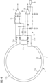
- the MRI system 1 comprises a device with at least one conductor loop 4, which runs within a loop plane and is arranged in particular in the imaging volume 3 such that the loop plane is oriented substantially parallel to the z-direction.
- the gradient coil 2 generates an alternating magnetic field in the imaging volume 3 , controlled by the control unit 5.
- This alternating magnetic field generally has magnetic field components in all three spatial directions x, y, z. Consequently, an induced voltage is generated in the at least one conductor loop 4, even if the loop plane is oriented substantially parallel to the z-direction.
- this can include the device or at least one conductor loop 4. The position of the device then corresponds to the position of the local MR receiving coil.
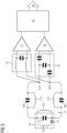
- the capacitances of the tuning capacitors 9a, 9b are tuned in particular such that they resonate with the inductance of the at least one conductor loop 4 at the Larmor resonance frequency of the MRI system 1, which, depending on the field strength, can be a high frequency, for example in the range of 1 MHz to 500 MHz.
- FIG 5 shows schematically a receiving element of a device in a further embodiment of the MRI system 1 according to the invention.
- the receiving element is based on the FIG 3 shown receiving element.
- FIG 6 is a flexible MR receiving coil 28 with several receiving elements, the corresponding conductor loops 4 wherein the receiving elements can be embedded, for example, in a flexible plastic material 26 and can be connected to a controller 27.
- FIG 7 shows schematically a flexible MR receiving coil 28 for imaging the head of the patient 29, FIG 8 a flexible MR receiving coil 28 for imaging the patient’s knee 29 and FIG 9 a flexible MR receiving coil 28 for imaging the abdomen of the patient 29.
- This type of pre-optimization accelerates the conversion speed of the iterative algorithm by reducing the number of coefficients A through J and setting a starting point closer to the final solution.
- the same consideration also applies to coil offset and coil rotation.
- the numerical range in which these parameters change can be restricted. , thus forcing the iterative algorithm to stay close to the final solution.
- the invention can also be advantageously applied to wireless coils that combine an analog-to-digital converter on the coil with a wireless transmission of digital signals.
- the methods described above can be variably combined with already known methods for detecting patient movement, such as Hall sensors, 2D or 3D video cameras or MR motion navigators, to further refine and improve the results.
Landscapes
- Health & Medical Sciences (AREA)
- Physics & Mathematics (AREA)
- Life Sciences & Earth Sciences (AREA)
- General Physics & Mathematics (AREA)
- Nuclear Medicine, Radiotherapy & Molecular Imaging (AREA)
- Engineering & Computer Science (AREA)
- General Health & Medical Sciences (AREA)
- Pathology (AREA)
- Condensed Matter Physics & Semiconductors (AREA)
- Medical Informatics (AREA)
- Biophysics (AREA)
- Biomedical Technology (AREA)
- Heart & Thoracic Surgery (AREA)
- Molecular Biology (AREA)
- Surgery (AREA)
- Animal Behavior & Ethology (AREA)
- Public Health (AREA)
- Veterinary Medicine (AREA)
- Radiology & Medical Imaging (AREA)
- High Energy & Nuclear Physics (AREA)
- Theoretical Computer Science (AREA)
- Magnetic Resonance Imaging Apparatus (AREA)
Priority Applications (4)
| Application Number | Priority Date | Filing Date | Title |
|---|---|---|---|
| EP22154982.7A EP4224189B1 (de) | 2022-02-03 | 2022-02-03 | Lagebestimmung einer vorrichtung in einem mrt-system |
| JP2023005283A JP7665662B2 (ja) | 2022-02-03 | 2023-01-17 | Mrtシステムにおける装置の位置の決定 |
| CN202310127159.9A CN116543062A (zh) | 2022-02-03 | 2023-02-02 | 确定装置在磁共振治疗系统内的位置 |
| US18/105,381 US20230284928A1 (en) | 2022-02-03 | 2023-02-03 | Determining a location of an apparatus in an mrt system |
Applications Claiming Priority (1)
| Application Number | Priority Date | Filing Date | Title |
|---|---|---|---|
| EP22154982.7A EP4224189B1 (de) | 2022-02-03 | 2022-02-03 | Lagebestimmung einer vorrichtung in einem mrt-system |
Publications (3)
| Publication Number | Publication Date |
|---|---|
| EP4224189A1 EP4224189A1 (de) | 2023-08-09 |
| EP4224189B1 true EP4224189B1 (de) | 2025-07-02 |
| EP4224189C0 EP4224189C0 (de) | 2025-07-02 |
Family
ID=80225974
Family Applications (1)
| Application Number | Title | Priority Date | Filing Date |
|---|---|---|---|
| EP22154982.7A Active EP4224189B1 (de) | 2022-02-03 | 2022-02-03 | Lagebestimmung einer vorrichtung in einem mrt-system |
Country Status (4)
| Country | Link |
|---|---|
| US (1) | US20230284928A1 (cg-RX-API-DMAC7.html) |
| EP (1) | EP4224189B1 (cg-RX-API-DMAC7.html) |
| JP (1) | JP7665662B2 (cg-RX-API-DMAC7.html) |
| CN (1) | CN116543062A (cg-RX-API-DMAC7.html) |
Family Cites Families (15)
| Publication number | Priority date | Publication date | Assignee | Title |
|---|---|---|---|---|
| CH231157A (de) * | 1941-10-30 | 1944-02-29 | Fides Gmbh | Schaltungsanordnung in Fernsprechanlagen mit mit mehreren Abzweigstellen versehenen Verbindungsleitungen. |
| US5307808A (en) * | 1992-04-01 | 1994-05-03 | General Electric Company | Tracking system and pulse sequences to monitor the position of a device using magnetic resonance |
| US5715822A (en) * | 1995-09-28 | 1998-02-10 | General Electric Company | Magnetic resonance devices suitable for both tracking and imaging |
| DE69942912D1 (de) * | 1998-09-08 | 2010-12-16 | Robin Medical Inc | Verfahren und vorrichtung zur abschätzung des ortes und der orientation von objekten während kernmagnetresonanzbildgebung |
| US6534982B1 (en) * | 1998-12-23 | 2003-03-18 | Peter D. Jakab | Magnetic resonance scanner with electromagnetic position and orientation tracking device |
| US6946836B2 (en) * | 2000-04-25 | 2005-09-20 | Kabushiki Kaisha Toshiba | Magnetic resonance imaging involving movement of patient's couch |
| JP4718714B2 (ja) | 2000-04-25 | 2011-07-06 | 株式会社東芝 | 磁気共鳴イメージング装置及び磁気共鳴イメージング方法 |
| US8228065B2 (en) | 2006-12-22 | 2012-07-24 | Koninklijke Philips Electronics N.V. | Transmission line for use in magnetic resonance system |
| WO2013013680A1 (de) * | 2011-07-22 | 2013-01-31 | MAX-PLANCK-Gesellschaft zur Förderung der Wissenschaften e.V. | Antenne und antennenanordnung für magnetresonanz-anwendungen |
| DE102012210507B4 (de) * | 2012-06-21 | 2016-06-16 | Siemens Healthcare Gmbh | Lokalspule für ein Magnetresonanzbildgebungssystem und Magnetresonanzbildgebungssystem |
| US9880242B2 (en) * | 2014-10-22 | 2018-01-30 | Duke University | RF coil elements with split DC loops for magnetic resonance imaging systems for integrated parallel reception, excitation, and shimming and related methods and devices |
| JP7171566B2 (ja) * | 2016-11-23 | 2022-11-15 | ゼネラル・エレクトリック・カンパニイ | Mrイメージング用の無線周波数コイルのシステム |
| GB2574672B (en) * | 2018-06-15 | 2021-02-24 | Univ Cape Town | A wireless radio frequency triggered signal acquisition device |
| CN215078496U (zh) * | 2021-01-14 | 2021-12-10 | 华中科技大学同济医学院附属协和医院 | 一种磁共振双膝关节线圈 |
| JP7606373B2 (ja) * | 2021-03-16 | 2024-12-25 | キヤノンメディカルシステムズ株式会社 | 生体情報モニタ装置及び磁気共鳴イメージング装置 |
-
2022
- 2022-02-03 EP EP22154982.7A patent/EP4224189B1/de active Active
-
2023
- 2023-01-17 JP JP2023005283A patent/JP7665662B2/ja active Active
- 2023-02-02 CN CN202310127159.9A patent/CN116543062A/zh active Pending
- 2023-02-03 US US18/105,381 patent/US20230284928A1/en active Pending
Also Published As
| Publication number | Publication date |
|---|---|
| JP2023113575A (ja) | 2023-08-16 |
| EP4224189C0 (de) | 2025-07-02 |
| EP4224189A1 (de) | 2023-08-09 |
| CN116543062A (zh) | 2023-08-04 |
| JP7665662B2 (ja) | 2025-04-21 |
| US20230284928A1 (en) | 2023-09-14 |
Similar Documents
| Publication | Publication Date | Title |
|---|---|---|
| DE102013214867B4 (de) | Ermittlung einer Magnetresonanz-Ansteuersequenz mit konzentrischen, kreisförmigen Sendetrajektorien | |
| DE102009004183B4 (de) | Magnetresonanztomographie-Vorrichtung mit Lokalisierungssystem und Verfahren zum Lokalisieren einer Lokalspule | |
| DE102004002009B4 (de) | Verfahren zum Betrieb eines Magnetresonanzsystems, Magnetresonanzsystem und Computerprogrammprodukt | |
| DE112011104494B4 (de) | Verfahren zur Reduzierung der deponierten Leistung bei Magnetresonanz- Tomografie unter Verwendung von Vielband-Pulsen und Vielkanal-Übertragung | |
| DE102006011253B4 (de) | Magnet-Resonanz-Bildgebung mit verbessertem Kontrast zwischen weißer und grauer Hirnsubstanz sowie CSF auf Basis einer Gradientenechosequenz | |
| DE10207736B4 (de) | Verfahren zur Bestimmung der Position einer Lokalantenne | |
| DE102004057310A1 (de) | Verfahren und Vorrichtung zum Reduzieren der HF-Energieeinstrahlung während einer MR-Datenakquisition | |
| DE102012216353B3 (de) | Ansteuerung eines Magnetresonanzsystems zur selektiven Anregung von Teilbereichen | |
| DE102014226034B4 (de) | Bildkorrektur bei der MR-Bildgebung unter Berücksichtigung des Empfangsprofils | |
| DE10338075B4 (de) | Verfahren zur ortsaufgelösten Messung der B1-Feldverteilung bei MR-Messungen | |
| DE112016005183T5 (de) | Magnetresonanz-Untersuchungssystem mit einer Benutzeroberfläche | |
| DE102020202830A1 (de) | Magnetresonanztomograph und Verfahren zum Betrieb mit dynamischer B0-Kompensation | |
| EP3709040B1 (de) | Verfahren zum betrieb einer magnetfeldkamera | |
| DE102014206011A1 (de) | Verfahren zur Aufnahme von Magnetresonanzdaten eines ein Metallobjekt enthaltenden Zielbereichs und Magnetresonanzeinrichtung | |
| DE102011083871B4 (de) | Anpassung der Grundfrequenz eines HF-Anregungspulses bei der nicht-selektiven Anregung von Kernspinsignalen in einem Untersuchungsobjekt | |
| DE10354941A1 (de) | Verfahren zur Bestimmung der B1-Feldstärke bei MR-Messungen | |
| DE102010061568A1 (de) | System und Verfahren zur Modellierung der durch den Gradientenspulenbetrieb hervorgerufenen Magnetfelddrift | |
| DE102017200446A1 (de) | Korrektur eines MR-Sendesignals | |
| EP4465068A1 (de) | Magnetresonanztomograph zur lokalisierung metallischer objekte und verfahren zum betrieb | |
| DE102014201944B4 (de) | HF-Puls-Justage-Verfahren und HF-Puls-Justage-Einrichtung | |
| DE102010063565B4 (de) | Verfahren und Einrichtung zur Ermittlung einer Magnetresonanzsystem-Ansteuersequenz | |
| DE102013207390A1 (de) | Ermittlung einer Magnetresonanz-Ansteuersequenz | |
| DE10151667C2 (de) | Verfahren zur Berechnung eines schaltbaren Gradientensystems für ein Magnet-Resonanz-Tomographiegerät | |
| EP4224189A1 (de) | Lagebestimmung einer vorrichtung in einem mrt-system | |
| DE102009012851B4 (de) | Verfahren, Magnetresonanzgerät, Computerprogrammprodukt und elektronisch lesbarer Datenträger zur Gewinnung eines ersten Bilddatensatzes und eines zweiten Bilddatensatzes eines Untersuchungsobjekts |
Legal Events
| Date | Code | Title | Description |
|---|---|---|---|
| PUAI | Public reference made under article 153(3) epc to a published international application that has entered the european phase |
Free format text: ORIGINAL CODE: 0009012 |
|
| STAA | Information on the status of an ep patent application or granted ep patent |
Free format text: STATUS: THE APPLICATION HAS BEEN PUBLISHED |
|
| AK | Designated contracting states |
Kind code of ref document: A1 Designated state(s): AL AT BE BG CH CY CZ DE DK EE ES FI FR GB GR HR HU IE IS IT LI LT LU LV MC MK MT NL NO PL PT RO RS SE SI SK SM TR |
|
| STAA | Information on the status of an ep patent application or granted ep patent |
Free format text: STATUS: REQUEST FOR EXAMINATION WAS MADE |
|
| RAP1 | Party data changed (applicant data changed or rights of an application transferred) |
Owner name: SIEMENS HEALTHINEERS AG |
|
| 17P | Request for examination filed |
Effective date: 20240119 |
|
| RBV | Designated contracting states (corrected) |
Designated state(s): AL AT BE BG CH CY CZ DE DK EE ES FI FR GB GR HR HU IE IS IT LI LT LU LV MC MK MT NL NO PL PT RO RS SE SI SK SM TR |
|
| GRAP | Despatch of communication of intention to grant a patent |
Free format text: ORIGINAL CODE: EPIDOSNIGR1 |
|
| STAA | Information on the status of an ep patent application or granted ep patent |
Free format text: STATUS: GRANT OF PATENT IS INTENDED |
|
| INTG | Intention to grant announced |
Effective date: 20250225 |
|
| GRAS | Grant fee paid |
Free format text: ORIGINAL CODE: EPIDOSNIGR3 |
|
| GRAA | (expected) grant |
Free format text: ORIGINAL CODE: 0009210 |
|
| STAA | Information on the status of an ep patent application or granted ep patent |
Free format text: STATUS: THE PATENT HAS BEEN GRANTED |
|
| AK | Designated contracting states |
Kind code of ref document: B1 Designated state(s): AL AT BE BG CH CY CZ DE DK EE ES FI FR GB GR HR HU IE IS IT LI LT LU LV MC MK MT NL NO PL PT RO RS SE SI SK SM TR |
|
| REG | Reference to a national code |
Ref country code: GB Ref legal event code: FG4D Free format text: NOT ENGLISH |
|
| REG | Reference to a national code |
Ref country code: CH Ref legal event code: EP |
|
| REG | Reference to a national code |
Ref country code: DE Ref legal event code: R096 Ref document number: 502022004447 Country of ref document: DE |
|
| REG | Reference to a national code |
Ref country code: IE Ref legal event code: FG4D Free format text: LANGUAGE OF EP DOCUMENT: GERMAN |
|
| U01 | Request for unitary effect filed |
Effective date: 20250717 |
|
| U07 | Unitary effect registered |
Designated state(s): AT BE BG DE DK EE FI FR IT LT LU LV MT NL PT RO SE SI Effective date: 20250724 |
|
| PG25 | Lapsed in a contracting state [announced via postgrant information from national office to epo] |
Ref country code: IS Free format text: LAPSE BECAUSE OF FAILURE TO SUBMIT A TRANSLATION OF THE DESCRIPTION OR TO PAY THE FEE WITHIN THE PRESCRIBED TIME-LIMIT Effective date: 20251102 |
|
| PG25 | Lapsed in a contracting state [announced via postgrant information from national office to epo] |
Ref country code: NO Free format text: LAPSE BECAUSE OF FAILURE TO SUBMIT A TRANSLATION OF THE DESCRIPTION OR TO PAY THE FEE WITHIN THE PRESCRIBED TIME-LIMIT Effective date: 20251002 |
|
| PG25 | Lapsed in a contracting state [announced via postgrant information from national office to epo] |
Ref country code: HR Free format text: LAPSE BECAUSE OF FAILURE TO SUBMIT A TRANSLATION OF THE DESCRIPTION OR TO PAY THE FEE WITHIN THE PRESCRIBED TIME-LIMIT Effective date: 20250702 |
|
| PG25 | Lapsed in a contracting state [announced via postgrant information from national office to epo] |
Ref country code: GR Free format text: LAPSE BECAUSE OF FAILURE TO SUBMIT A TRANSLATION OF THE DESCRIPTION OR TO PAY THE FEE WITHIN THE PRESCRIBED TIME-LIMIT Effective date: 20251003 |
|
| PG25 | Lapsed in a contracting state [announced via postgrant information from national office to epo] |
Ref country code: CZ Free format text: LAPSE BECAUSE OF FAILURE TO SUBMIT A TRANSLATION OF THE DESCRIPTION OR TO PAY THE FEE WITHIN THE PRESCRIBED TIME-LIMIT Effective date: 20250702 |
|
| PG25 | Lapsed in a contracting state [announced via postgrant information from national office to epo] |
Ref country code: PL Free format text: LAPSE BECAUSE OF FAILURE TO SUBMIT A TRANSLATION OF THE DESCRIPTION OR TO PAY THE FEE WITHIN THE PRESCRIBED TIME-LIMIT Effective date: 20250702 |
|
| PG25 | Lapsed in a contracting state [announced via postgrant information from national office to epo] |
Ref country code: RS Free format text: LAPSE BECAUSE OF FAILURE TO SUBMIT A TRANSLATION OF THE DESCRIPTION OR TO PAY THE FEE WITHIN THE PRESCRIBED TIME-LIMIT Effective date: 20251002 |
|
| PG25 | Lapsed in a contracting state [announced via postgrant information from national office to epo] |
Ref country code: ES Free format text: LAPSE BECAUSE OF FAILURE TO SUBMIT A TRANSLATION OF THE DESCRIPTION OR TO PAY THE FEE WITHIN THE PRESCRIBED TIME-LIMIT Effective date: 20250702 |
|
| U20 | Renewal fee for the european patent with unitary effect paid |
Year of fee payment: 5 Effective date: 20260219 |
|
| PG25 | Lapsed in a contracting state [announced via postgrant information from national office to epo] |
Ref country code: SM Free format text: LAPSE BECAUSE OF FAILURE TO SUBMIT A TRANSLATION OF THE DESCRIPTION OR TO PAY THE FEE WITHIN THE PRESCRIBED TIME-LIMIT Effective date: 20250702 |
|
| PGFP | Annual fee paid to national office [announced via postgrant information from national office to epo] |
Ref country code: GB Payment date: 20260310 Year of fee payment: 5 |
|
| PG25 | Lapsed in a contracting state [announced via postgrant information from national office to epo] |
Ref country code: SK Free format text: LAPSE BECAUSE OF FAILURE TO SUBMIT A TRANSLATION OF THE DESCRIPTION OR TO PAY THE FEE WITHIN THE PRESCRIBED TIME-LIMIT Effective date: 20250702 |
|
| PLBE | No opposition filed within time limit |
Free format text: ORIGINAL CODE: 0009261 |
|
| STAA | Information on the status of an ep patent application or granted ep patent |
Free format text: STATUS: NO OPPOSITION FILED WITHIN TIME LIMIT |
|
| REG | Reference to a national code |
Ref country code: CH Ref legal event code: L10 Free format text: ST27 STATUS EVENT CODE: U-0-0-L10-L00 (AS PROVIDED BY THE NATIONAL OFFICE) Effective date: 20260518 |
|
| 26N | No opposition filed |
Effective date: 20260407 |