EP4224174A1 - Clamp sensor - Google Patents
Clamp sensor Download PDFInfo
- Publication number
- EP4224174A1 EP4224174A1 EP23150552.0A EP23150552A EP4224174A1 EP 4224174 A1 EP4224174 A1 EP 4224174A1 EP 23150552 A EP23150552 A EP 23150552A EP 4224174 A1 EP4224174 A1 EP 4224174A1
- Authority
- EP
- European Patent Office
- Prior art keywords
- contact portion
- clamp arm
- clamp
- conductor
- contact
- Prior art date
- Legal status (The legal status is an assumption and is not a legal conclusion. Google has not performed a legal analysis and makes no representation as to the accuracy of the status listed.)
- Granted
Links
Images




Classifications
-
- G—PHYSICS
- G01—MEASURING; TESTING
- G01R—MEASURING ELECTRIC VARIABLES; MEASURING MAGNETIC VARIABLES
- G01R15/00—Details of measuring arrangements of the types provided for in groups G01R17/00 - G01R29/00, G01R33/00 - G01R33/26 or G01R35/00
- G01R15/14—Adaptations providing voltage or current isolation, e.g. for high-voltage or high-current networks
- G01R15/18—Adaptations providing voltage or current isolation, e.g. for high-voltage or high-current networks using inductive devices, e.g. transformers
- G01R15/186—Adaptations providing voltage or current isolation, e.g. for high-voltage or high-current networks using inductive devices, e.g. transformers using current transformers with a core consisting of two or more parts, e.g. clamp-on type
-
- G—PHYSICS
- G01—MEASURING; TESTING
- G01R—MEASURING ELECTRIC VARIABLES; MEASURING MAGNETIC VARIABLES
- G01R1/00—Details of instruments or arrangements of the types included in groups G01R5/00 - G01R13/00 and G01R31/00
- G01R1/02—General constructional details
- G01R1/04—Housings; Supporting members; Arrangements of terminals
- G01R1/0408—Test fixtures or contact fields; Connectors or connecting adaptors; Test clips; Test sockets
- G01R1/0425—Test clips, e.g. for IC's
-
- G—PHYSICS
- G01—MEASURING; TESTING
- G01R—MEASURING ELECTRIC VARIABLES; MEASURING MAGNETIC VARIABLES
- G01R1/00—Details of instruments or arrangements of the types included in groups G01R5/00 - G01R13/00 and G01R31/00
- G01R1/02—General constructional details
- G01R1/18—Screening arrangements against electric or magnetic fields, e.g. against earth's field
-
- G—PHYSICS
- G01—MEASURING; TESTING
- G01R—MEASURING ELECTRIC VARIABLES; MEASURING MAGNETIC VARIABLES
- G01R15/00—Details of measuring arrangements of the types provided for in groups G01R17/00 - G01R29/00, G01R33/00 - G01R33/26 or G01R35/00
- G01R15/14—Adaptations providing voltage or current isolation, e.g. for high-voltage or high-current networks
- G01R15/142—Arrangements for simultaneous measurements of several parameters employing techniques covered by groups G01R15/14 - G01R15/26
-
- G—PHYSICS
- G01—MEASURING; TESTING
- G01R—MEASURING ELECTRIC VARIABLES; MEASURING MAGNETIC VARIABLES
- G01R15/00—Details of measuring arrangements of the types provided for in groups G01R17/00 - G01R29/00, G01R33/00 - G01R33/26 or G01R35/00
- G01R15/14—Adaptations providing voltage or current isolation, e.g. for high-voltage or high-current networks
- G01R15/16—Adaptations providing voltage or current isolation, e.g. for high-voltage or high-current networks using capacitive devices
-
- G—PHYSICS
- G01—MEASURING; TESTING
- G01R—MEASURING ELECTRIC VARIABLES; MEASURING MAGNETIC VARIABLES
- G01R15/00—Details of measuring arrangements of the types provided for in groups G01R17/00 - G01R29/00, G01R33/00 - G01R33/26 or G01R35/00
- G01R15/14—Adaptations providing voltage or current isolation, e.g. for high-voltage or high-current networks
- G01R15/20—Adaptations providing voltage or current isolation, e.g. for high-voltage or high-current networks using galvano-magnetic devices, e.g. Hall-effect devices, i.e. measuring a magnetic field via the interaction between a current and a magnetic field, e.g. magneto resistive or Hall effect devices
-
- G—PHYSICS
- G01—MEASURING; TESTING
- G01R—MEASURING ELECTRIC VARIABLES; MEASURING MAGNETIC VARIABLES
- G01R31/00—Arrangements for testing electric properties; Arrangements for locating electric faults; Arrangements for electrical testing characterised by what is being tested not provided for elsewhere
Definitions
- the present invention relates to a clamp sensor that clamps a measurement object and measures a measured amount of the measurement object.
- Patent Literature 1 describes a structure of pivoting a pair of clamp arms (also referred to as clip pieces) having different lengths from a pivoting axis about the pivoting axis in directions approaching each other to clamp an electric wire being a measurement object between the pair of clamp arms. According to this structure, it is possible to more reliably clamp a plurality of types of electrical wires having different diameters and measure a measurement amount of the electrical wire, for example, a voltage applied to the electrical wire and a current flowing through the electrical wire.
- Patent Literature 1 JP 2018-13500 A
- each clamp arm is provided with an electromagnetic wave shield or an electrode.
- the pair of clamp arms is separated from each other. Accordingly, a gap is generated between the electromagnetic wave shields or the electrodes provided in the respective clamp arms. As a result, there is a possibility that the shield performance is deteriorated due to the influence of the noise through the gap or the measurement accuracy of the electric wire through the electrode is deteriorated.
- a third clamp arm for surrounding the outer periphery of the electric wire.
- the third clamp arm forms a cylindrical shape having an inner diameter larger than the maximum diameter of an electric wire that can be clamped by the clamp sensor by making contact with one of the pair of clamp arms. Accordingly, the outer periphery of the electric wire can be surrounded by a shield or an electrode provided on the third clamp arm and the shield or the electrode provided on one of the pair of clamp arms regardless of the diameter of the electric wire.
- the third clamp arm is a separate member from the pair of clamp arms. Therefore, a means for preventing a contact failure between the shield or the electrode provided on the third clamp arm and the shield or the electrode provided on one of the pair of clamp arms is required. For example, it is conceivable to connect two shields or electrodes with a cable disposed outside the clamp arm. However, the cable may inhibit the motion of the clamp arm.
- an object of the present invention is to solve the above problem, and to provide a clamp sensor capable of reducing a possibility of contact failure between two conductors surrounding an outer periphery of a measurement object.
- the present invention is configured as follows.
- a clamp sensor includes: a first clamp arm configured to pivot about a pivoting axis; a second clamp arm configured to pivot about the pivoting axis, the second clamp arm configured to clamp a measurement object in cooperation with the first clamp arm; a measurement unit provided on at least one of the first clamp arm and the second clamp arm, the measurement unit configured to measure a measured amount of the measurement object clamped by the first clamp arm and the second clamp arm; a first conductor provided on the first clamp arm so as to face an outer circumferential surface of the measurement object clamped by the first clamp arm and the second clamp arm, the first conductor including a first contact portion configured to come into contact with and separate from the second clamp arm; and a second conductor provided on the second clamp arm so as to face an outer circumferential surface of the measurement object clamped by the first clamp arm and the second clamp arm, the second conductor including a second contact portion configured to come into contact with and separate from the first contact portion.
- the first contact portion and the second contact portion come into contact with each other
- a clamp sensor includes: a first clamp arm configured to pivot about a pivoting axis; a second clamp arm configured to pivot about the pivoting axis, the second clamp arm configured to clamp a measurement object in cooperation with the first clamp arm; a measurement unit provided on at least one of the first clamp arm and the second clamp arm, the measurement unit configured to measure a measured amount of the measurement object clamped by the first clamp arm and the second clamp arm; a first conductor provided on the first clamp arm so as to face an outer circumferential surface of the measurement object clamped by the first clamp arm and the second clamp arm, the first conductor including a first contact portion configured to come into contact with and separate from the second clamp arm; and a second conductor provided on the second clamp arm so as to face an outer circumferential surface of the measurement object clamped by the first clamp arm and the second clamp arm, the second conductor including a second contact portion configured to come into contact with and separate from the first contact portion.
- the first contact portion and the second contact portion come into contact with each other
- the first contact portion of the first conductor and the second contact portion of the second conductor are not only in contact with each other, but one of the first contact portion and the second contact portion presses the other. Accordingly, between the first conductor and the second conductor, an elastic force against the counterpart acts. As a result, the contact strength between the first conductor and the second conductor increases. As a result, the possibility of contact failure between the first conductor and the second conductor can be reduced.
- the first contact portion may be positioned at a tip portion of the first clamp arm.
- the second contact portion may be positioned at a tip portion of the second clamp arm.
- the tip portions of the first clamp arm and the second clamp arm are farther away from the pivoting axis than the base end portion. Therefore, the elastic force when the tip portions of the first clamp arm and the second clamp arm are in contact with each other can be made larger than the elastic force when the base end portions of the first clamp arm and the second clamp arm are in contact with each other. That is, according to this configuration, the elastic force acting between the first contact portion and the second contact portion can be increased. Accordingly, the contact strength between the first contact portion and the second contact portion can be increased.
- the first conductor may include a plurality of the first contact portions.
- the second conductor may include a plurality of the second contact portions provided on a one-by-one basis correspondingly to each of the plurality of first contact portions.
- the first conductor may be formed by coating the first clamp arm with a conductive material.
- the second conductor may be formed by coating the second clamp arm with a conductive material.
- At least one of the first clamp arm and the second clamp arm may include a projection.
- the projection may be provided at the same position as the first contact portion and the second contact portion in an insertion direction of the measurement object into the clamp sensor when the measurement object is clamped by the first clamp arm and the second clamp arm, or at a position upstream of the first contact portion and the second contact portion in the insertion direction.
- the projection included in the first clamp arm may protrude more toward the second contact portion than toward the first contact portion as viewed from a width direction parallel to the pivoting axis.
- the projection included in the second clamp arm may protrude more toward the first contact portion than toward the second contact portion as viewed from the width direction.
- the projection is positioned at the same position in the insertion direction as the first contact portion and the second contact portion or upstream of the first contact portion and the second contact portion in the insertion direction.
- the projection protrudes larger than the first contact portion and the second contact portion. Therefore, when the measurement object is inserted along the insertion direction between the first clamp arm and the second clamp arm, the projection can inhibit the measurement object from coming into contact with the first contact portion and the second contact portion. Accordingly, it is possible to reduce the possibility that the first contact portion and the second contact portion are worn or damaged by coming into contact with the measurement object.
- the first conductor and the second conductor may have an electromagnetic wave shielding function for the measurement object clamped by the first clamp arm and the second clamp arm.
- the outer circumferential surface of the measurement object can be largely surrounded in the circumferential direction by the electromagnetic wave shield including the first conductor and the second conductor connected to each other. Therefore, it is possible to enhance the shielding effect against the electromagnetic wave that may affect the measurement object.
- the first conductor and the second conductor may be electrodes functioning as the measurement units.
- the electrodes including the first conductor and the second conductor connected to each other can largely surround the outer circumferential surface of the measurement object in the circumferential direction. Therefore, the measurement accuracy by the measurement unit can be improved.
- the first conductor may include: a first shield conductor having an electromagnetic wave shielding function for the measurement object clamped by the first clamp arm and the second clamp arm; and a first electrode functioning as the measurement unit.
- the second conductor may include: a second shield conductor having an electromagnetic wave shielding function for the measurement object clamped by the first clamp arm and the second clamp arm; and a second electrode functioning as the measurement unit.
- Each of the first shield conductor and the first electrode may include the first contact portion.
- Each of the second shield conductor and the second electrode may include the second contact portion.
- the first contact portion of the first shield conductor and the second contact portion of the second shield conductor may come into contact with each other and separate from each other.
- the first contact portion of the first electrode and the second contact portion of the second electrode may come into contact with each other and separate from each other.
- the outer circumference of the measurement object can be largely surrounded by the electromagnetic wave shield including the first contact portion and the second contact portion connected to each other. Therefore, it is possible to enhance the shielding effect against the electromagnetic wave that may affect the measurement object.
- the outer circumference of the measurement object can be largely surrounded by the electrodes including the first contact portion and the second contact portion connected to each other. Therefore, the measurement accuracy by the measurement unit can be improved.
- the first contact portion of the first shield conductor and the second contact portion of the second shield conductor may be positioned on one of an opposite side from the pivoting axis with respect to a clamping position at which the measurement object is clamped by the first clamp arm and the second clamp arm and the pivoting axis side with respect to the clamping position.
- the first contact portion of the first electrode and the second contact portion of the second electrode may be positioned on the other of an opposite side from the pivoting axis with respect to the clamping position and the pivoting axis side with respect to the clamping position.
- the first contact portion of the first shield conductor and the second contact portion of the second shield conductor, and the first contact portion of the first electrode and the second contact portion of the second electrode are positioned on sides opposite to each other across a clamping position. Therefore, the arrangement space of the contact portion of the shield conductor and the arrangement space of the contact portion of the electrode are not reduced by the arrangement space of the counterpart.
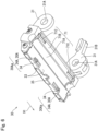
- Fig. 1 is a perspective view of a clamp sensor according to an embodiment of the present invention.
- Fig. 2 is an exploded perspective view of the clamp sensor according to the embodiment of the present invention.
- Fig. 3 is a perspective view of the clamp sensor in which the cover member is removed from Fig. 1 .
- the clamp sensor 10 includes clamp arms 20, 30, and 40 and a shaft 50.
- the clamp arm 30 is an example of a first clamp arm.
- the clamp arm 40 is an example of a second clamp arm.
- the clamp arms 20 and 40 are configured to be able to clamp the measurement object 60 in cooperation with each other.
- the clamp arms 30 and 40 are configured to be able to clamp the measurement object 60 while covering the outer circumferential surface 60A of the measurement object 60 in cooperation with each other.
- the measurement object 60 is an electric wire. It should be noted that the clamp sensor 10 according to the present embodiment can clamp a plurality of types of electric wires having different diameters.
- the clamp arm 20 is configured to pivot about a pivoting axis 51.
- the shaft 50 passes through the through hole 21A provided in the clamp arm 20.
- the pivoting axis 51 is an imaginary line passing through the center of the shaft 50.
- the clamp arm 20 is biased by a biasing member (not shown) such as a torsion coil spring so as to pivot in a direction approaching the clamp arm 40 about the pivoting axis 51.
- the clamp arm 20 includes a main body portion 21 and a pair of arm portions 22 protruding from the main body portion 21.
- the respective arm portions 22 protrude from both end portions of the main body portion 21 in the width direction 91 parallel to the pivoting axis 51.
- Each arm portion 22 has the above-described through hole 21A and a pressing surface 21B.
- the pressing surface 21B is curved in an arc shape as viewed from the width direction 91.
- the curvature of the pressing surface 21B is set in accordance with the diameter of the measurement object 60 (for example, equal to or slightly larger than the diameter of the measurement object 60).
- the clamp arm 30 is configured to pivot about the pivoting axis 51.
- the clamp arm 30 is provided between the pair of arm portions 22 of the clamp arm 20.
- the shaft 50 passes through the through hole 31A provided in the clamp arm 30.
- the clamp arm 30 is biased by a biasing member (not shown) such as a torsion coil spring so as to pivot in a direction approaching the clamp arm 40 about the pivoting axis 51.
- the clamp arm 30 has a pair of protrusions 31.
- Each protrusion 31 has the above-described through hole 31A.
- One of the pair of protrusions 31 has a protruding portion 31B.
- the protruding portion 31B is opposed to the main body portion 21 of the clamp arm 20 in a pivoting direction (a circumferential direction around the pivoting axis 51) of the clamp arms 20, 30, and 40. When the main body portion 21 of the pivoting clamp arm 20 presses the protrusion 31, the clamp arm 30 pivots.
- the clamp arm 30 includes a cover member 33, a pair of projections 34, and a projection 35.
- the cover member 33 covers the projection 34.
- the cover member 33 is attachable to and detachable from the clamp arm 30. In Figs. 1 and 2 , the cover member 33 is attached to the clamp arm 30. In Fig. 3 , the cover member 33 is detached from the clamp arm 30.
- the projections 34 and 35 are provided at the tip portion 32 of the clamp arm 30.
- the tip portion 32 of the clamp arm 30 is a portion farthest from the pivoting axis 51 in the radial direction orthogonal to the pivoting axis 51, in the clamp arm 30.
- the projections 34 and 35 protrude to approach the clamp arm 30 about the pivoting axis 51.
- the pair of projections 34 is provided at an interval in the width direction 91.
- the projection 35 is provided between the pair of projections 34 in the width direction 91. It should be noted that the positional relationship between the projections 34 and 35 is not limited to the above, and for example, the projection 35 may be provided outside the pair of projections 34 in the width direction 91.
- Fig. 4 is a perspective cross-sectional view of the clamp sensor according to the embodiment of the present invention.
- Fig. 5 is a right side view of Fig. 4 .
- the clamp arm 30 is provided with a first shield conductor 30A and a first electrode 71.
- Each of the first shield conductor 30A and the first electrode 71 is an example of a first conductor.
- the first shield conductor 30A is a conductive coating material (coating material containing a conductive material) applied over the inner surface of the clamp arm 30 and the tip surfaces 34A of the pair of projections 34.
- the first shield conductor 30A is formed so as to cover a part of the outer circumferential surface 60A of the measurement object 60 clamped by the clamp arms 20 and 40. That is, the first shield conductor 30A is provided on the clamp arm 30 so as to face the outer circumferential surface 60A of the measurement object 60 clamped between the clamp arms 20 and 40.
- the conductive coating material applied to the tip surfaces 34A of the pair of projections 34 is electrically connected to the conductive coating material applied to the other portion (the conductive coating material applied to the inner surface of the clamp arm 30).
- the first shield conductor 30A has a first contact portion 30Aa.
- the first contact portion 30Aa includes the pair of projections 34 and a conductive coating material (first shield conductor 30A) applied to the tip surface 34A of each of the pair of projections 34. That is, in the present embodiment, the first shield conductor 30A includes a plurality of first contact portions 30Aa.
- the first electrode 71 is a conductive plate disposed inside the clamp arm 30.
- the first electrode 71 includes an arc-shaped portion 71A and a protruding portion 71B.
- the arc-shaped portion 71A is curved in an arc shape as viewed from the width direction 91.
- the curvature of the arc-shaped portion 71A is set in accordance with the diameter of the measurement object 60 (for example, equal to or slightly larger than the diameter of the measurement object 60).
- the arc-shaped portion 71A covers a part of the outer circumferential surface 60A of the measurement object 60.
- the one end portion 71Aa in the circumferential direction of the arc-shaped portion 71A is positioned on the opposite side of the shaft 50 (in other words, the pivoting axis 51) with respect to the clamping position of the measurement object 60.
- the clamping position of the measurement object 60 is a position where the measurement object 60 is clamped between the clamp arms 20 and 30 and the clamp arm 40.
- the other end portion 71Ab in the circumferential direction of the arc-shaped portion 71A is positioned on the shaft 50 side with respect to the clamping position of the measurement object 60. That is, the other end portion 71Ab in the circumferential direction of the arc-shaped portion 71A is positioned between the clamping position of the measurement object 60 and the shaft 50.
- the protruding portion 71B protrudes toward the shaft 50 from the other end portion 71Ab in the circumferential direction of the arc-shaped portion 71A.
- the first shield conductor 30A is not limited to the conductive coating material, and the first electrode 71 is not limited to the conductive plate.
- the first shield conductor 30A may be a conductive plate disposed inside the clamp arm 30.
- the clamp arm 40 is configured to pivot about the pivoting axis 51.
- the clamp arm 40 is provided to face the clamp arms 20 and 30 in the pivoting direction of the clamp arms 20, 30, and 40.
- the shaft 50 passes through the through hole 41A provided in the clamp arm 40.
- the clamp arm 40 has a pair of protrusions 41. Each protrusion 41 has the above-described through hole 41A.
- the clamp arm 40 has receiving surfaces 40B at both end portions in the width direction 91.
- the receiving surface 40B is curved in an arc shape as viewed from the width direction 91.
- the curvature of the receiving surface 40B is set in accordance with the diameter of the measurement object 60 (for example, equal to or slightly larger than the diameter of the measurement object 60).
- the receiving surface 40B faces the pressing surface 21B of the clamp arm 20 in the pivoting direction, and can clamp the measurement object 60 between the receiving surface 40B and the pressing surface 21B.
- the clamp arm 40 includes a cover member 43, a pair of leaf spring portions 44, and a recess 45.
- the cover member 43 covers the leaf spring portion 44.
- the cover member 43 is attachable to and detachable from the clamp arm 40. In Figs. 1 and 2 , the cover member 43 is attached to the clamp arm 40. In Fig. 3 , the cover member 43 is detached from the clamp arm 40.
- the leaf spring portion 44 and the recess 45 are provided at the tip portion 42 of the clamp arm 40.
- the tip portion 42 of the clamp arm 40 is a portion farthest from the pivoting axis 51 in the radial direction orthogonal to the pivoting axis 51, in the clamp arm 40.
- Each of the pair of leaf spring portions 44 faces a corresponding one of the pair of projections 34 in the pivoting direction.
- Each of the pair of leaf spring portions 44 protrudes outward in the width direction 91 from the tip portion 42.
- Each of the pair of leaf spring portions 44 is inclined with respect to the width direction 91 so as to approach the projection 34 as it goes outward in the width direction 91.
- the leaf spring portion 44 can be bent in the pivoting direction by elastic deformation.
- the recess 45 is provided between the pair of leaf spring portions 44 in the width direction 91.
- the recess 45 faces the projection 35 in the pivoting direction.
- the projection 35 can be fitted into the recess 45 (see Figs. 1 and 3 ).
- the clamp arm 40 is provided with a second shield conductor 40A and a second electrode 72.
- Each of the second shield conductor 40A and the second electrode 72 is an example of a second conductor.
- the second shield conductor 40A is a conductive coating material applied over the inner surface of the clamp arm 40 and the opposing surfaces 44A of the pair of leaf spring portions 44.
- the opposing surfaces 44A of the pair of leaf spring portions 44 are surfaces facing the tip surface 34A of the projection 34 in the pivoting direction.
- the second shield conductor 40A is formed so as to cover a part of the outer circumferential surface 60A of the measurement object 60 clamped by the clamp arms 30 and 40. That is, the second shield conductor 40A is provided on the clamp arm 40 so as to face the outer circumferential surface 60A of the measurement object 60 clamped between the clamp arms 30 and 40.
- the conductive coating material applied to the opposing surfaces 44A of the pair of leaf spring portions 44 is electrically connected to the conductive coating material applied to the other portion (the conductive coating material applied to the inner surface of the clamp arm 40).
- the second shield conductor 40A has a second contact portion 40Aa.
- the second contact portion 40Aa includes the pair of leaf spring portions 44 and a conductive coating material (second shield conductor 40A) applied to the opposing surface 44A of each of the pair of leaf spring portions 44. That is, in the present embodiment, the second shield conductor 40A includes the plurality of second contact portions 40Aa provided on a one-by-one basis correspondingly to each of the plurality of first contact portions 30Aa.
- the second electrode 72 is a conductive plate disposed inside the clamp arm 40.
- the second electrode 72 includes an arc-shaped portion 72A and protruding portions 72B and 72C.
- the arc-shaped portion 72A is curved in an arc shape as viewed from the width direction 91.
- the curvature of the arc-shaped portion 72A is set in accordance with the diameter of the measurement object 60 (for example, equal to or slightly larger than the diameter of the measurement object 60).
- the arc-shaped portion 72A covers a part of the outer circumferential surface 60A of the measurement object 60 from the opposite side from the arc-shaped portion 71A of the first electrode 71. That is, the second electrode 72 clamps the measurement object 60 between the second electrode 72 and the first electrode 71. As shown in Fig.
- the one end portion 72Aa in the circumferential direction of the arc-shaped portion 72A is positioned on the opposite side of the shaft 50 (in other words, the pivoting axis 51) with respect to the clamping position of the measurement object 60.
- the other end portion in the circumferential direction of the arc-shaped portion 72A is positioned on the shaft 50 side with respect to the clamping position of the measurement object 60. That is, the other end portion in the circumferential direction of the arc-shaped portion 72A is positioned between the clamping position of the measurement object 60 and the shaft 50.
- the protruding portion 72B protrudes toward the shaft 50 from the other end portion in the circumferential direction of the arc-shaped portion 72A.
- the protruding portion 72C is provided adjacent to the protruding portion 72B in the width direction 91.
- the protruding portion 72C protrudes from the other end portion in the circumferential direction of the arc-shaped portion 72A.
- the protruding portion 72C protrudes in a direction away from the clamp arm 30 as viewed from the width direction 91.
- the protruding portion 72C is electrically connected to the printed circuit board 80 disposed inside the clamp arm 40.
- the printed circuit board 80 is mounted with various electronic components constituting a circuit for measuring the measured amount of the measurement object 60.
- the measured amount is a voltage applied to the measurement object 60 (electric wire) or a current flowing through the measurement object 60 (electric wire).
- the second shield conductor 40A is not limited to the conductive coating material, and the second electrode 72 is not limited to the conductive plate.
- the second shield conductor 40A may be a conductive plate disposed inside the clamp arm 40.
- the first contact portion 30Aa and the second contact portion 40Aa can be in contact with each other (see Fig. 3 ) and separated from each other (see Fig. 8 ).
- the first contact portion 30Aa (specifically, the first shield conductor 30A coated on the tip surface 34A of the projection 34) and the second contact portion 40Aa (specifically, the second shield conductor 40A coated on the opposing surface 44A of the leaf spring portion 44) come into contact with each other in a state where the second contact portion 40Aa is pressed by the first contact portion 30Aa and bent by elastic deformation.
- the first shield conductor 30A and the second shield conductor 40A are electrically connected to each other.
- the second shield conductor 40A is grounded.
- the second shield conductor 40A is electrically connected to the ground. Therefore, the first shield conductor 30A electrically connected to the second shield conductor 40A is also grounded.
- the first shield conductor 30A and the second shield conductor 40A face the outer circumferential surface 60A of the measurement object 60 clamped by the clamp arms 30 and 40 and surround the outer circumferential surface 60A.
- the first shield conductor 30A and the second shield conductor 40A have an electromagnetic wave shielding function with respect to the measurement object 60 clamped by the clamp arms 30 and 40.
- the first shield conductor 30A may be grounded instead of the second shield conductor 40A, or both the first shield conductor 30A and the second shield conductor 40A may be grounded.
- first shield conductor 30A and the second shield conductor 40A are in contact with each other at the tip portions 32 and 42, but are not in contact with each other on the opposite side from the tip portions 32 and 42 with respect to the clamping position of the measurement object 60.
- first shield conductor 30A and the second shield conductor 40A may be in contact with each other on the opposite side.
- the first electrode 71 and the second electrode 72 shown in Figs. 4 and 5 can be in contact with each other and can be separated from each other.
- the first electrode 71 and the second electrode 72 come into contact with each other. Specifically, one end portion 71Aa in the circumferential direction of the arc-shaped portion 71A of the first electrode 71 is in contact with and electrically connected to one end portion 72Aa in the circumferential direction of the arc-shaped portion 72A of the second electrode 72.
- the protruding portion 71B of the first electrode 71 is in contact with and electrically connected to the protruding portion 72B of the second electrode 72. Accordingly, the first electrode 71 and the second electrode 72 completely surround the measurement object 60 as viewed from the width direction 91.
- the measurement object 60 is an electric wire
- the electric wire includes a conductor and a covering portion covering the conductor.
- the first electrode 71 and the second electrode 72 face the conductor of the electric wire across the covering portion of the electric wire. That is, the first electrode 71 and the second electrode 72 are capacitively coupled to the measurement object 60 (specifically, the conductor of the electric wire), and function as a voltage detection element configured to measure the voltage (measured amount) applied to the conductor of the electric wire clamped by the clamp arms 30 and 40 in a non-contact manner. That is, the first electrode 71 and the second electrode 72 are an example of a measurement unit and an example of an electrode functioning as a measurement unit.
- Fig. 6 is a perspective view of a first clamp arm.
- the first electrode 71 includes a leaf spring portion 71C.
- the leaf spring portions 71C are provided at both end portions in the width direction 91 of the protruding portion 71B.
- the leaf spring portion 71C extends outward in the width direction 91 from the protruding portion 71B.
- the leaf spring portion 71C is inclined with respect to the width direction 91 so as to approach the protruding portion 72B of the second electrode 72 as it goes outward in the width direction 91.
- the leaf spring portion 71C can be bent in the pivoting direction by elastic deformation.
- Fig. 7 is a perspective cross-sectional view of the clamp sensor according to the embodiment of the present invention.
- each of the pair of leaf spring portions 71C of the first electrode 71 and the protruding portion 72B of the second electrode 72 can come into contact with each other.
- each of the pair of leaf spring portions 71C and the protruding portion 72B come into contact with each other.
- the protruding portion 72B presses the pair of leaf spring portions 71C in the pivoting direction. Accordingly, the pair of leaf spring portions 71C is bent in the pivoting direction by elastic deformation.
- the protruding portion 72B and the pair of leaf spring portions 71C come into contact with each other in a state where the pair of leaf spring portions 71C is pressed by the protruding portion 72B and is bent by elastic deformation.
- the first electrode 71 and the second electrode 72 are electrically connected to each other.
- the pair of leaf spring portions 71C is an example of the first contact portion
- the protruding portion 72B is an example of the second contact portion.
- the first electrode 71 and the second electrode 72 are in contact with each other on both sides of the clamping position of the measurement object 60. Accordingly, as described above, the first electrode 71 and the second electrode 72 completely surround the measurement object 60 as viewed from the width direction 91.
- the contact pressure in other words, the contact pressure of the one end portion 71Aa and the one end portion 72Aa
- the reliability of the contact of the one end portions 71Aa and 72Aa is improved.
- the contact pressure on the shaft 50 side (in other words, the contact pressure of the protruding portion 71B and the protruding portion 72B) becomes low, and the reliability of the contact of the protruding portions 71B and 72B may decrease.
- the reliability of contact between the leaf spring portion 71C and the protruding portion 72B can be favorably maintained.
- the first contact portion 30Aa of the first shield conductor 30A and the second contact portion 40Aa of the second shield conductor 40A are positioned on the opposite side from the shaft 50 (the pivoting axis 51) with respect to the clamping position of the measurement object 60 as shown in Fig. 5 .
- the pair of leaf spring portions 71C corresponding to the first contact portion of the first electrode 71 and the protruding portion 72B corresponding to the second contact portion of the second electrode 72 are positioned on the shaft 50 side with respect to the clamping position of the measurement object 60 as shown in Figs. 6 and 7 .
- first contact portion 30Aa of the first shield conductor 30A and the second contact portion 40Aa of the second shield conductor 40A, and the first contact portion of the first electrode 71 and the second contact portion of the second electrode 72 are positioned on the sides opposite to each other across the clamping position of the measurement object 60.
- the first contact portion 30Aa of the first shield conductor 30A and the second contact portion 40Aa of the second shield conductor 40A may be positioned on the shaft 50 side with respect to the clamping position of the measurement object 60.
- the pair of leaf spring portions 71C of the first electrode 71 and the protruding portion 72B of the second electrode 72 may be positioned on the opposite side from the shaft 50 with respect to the clamping position of the measurement object 60.
- both the first contact portion 30Aa of the first shield conductor 30A and the second contact portion 40Aa of the second shield conductor 40A, and the first contact portion of the first electrode 71 and the second contact portion of the second electrode 72 may be positioned on the same side with respect to the clamping position of the measurement object 60 (for example, both are on the opposite side from the shaft 50 with respect to the clamping position of the measurement object 60).
- Fig. 8 is a perspective view of the clamp sensor according to the embodiment of the present invention.
- Fig. 9 is a right side view of the clamp sensor according to the embodiment of the present invention.
- the projection 35 is provided at a position upstream of the first contact portion 30Aa and the second contact portion 40Aa in the insertion direction 92, in the insertion direction 92 of the measurement object 60 into the clamp sensor 10 when the measurement object 60 is clamped by the clamp arms 30 and 40.
- the projection 35 included in the clamp arm 30 protrudes more to the second contact portion 40Aa side than to the first contact portion 30Aa as viewed from the width direction 91.
- the projection 35 may be provided at the same position as the first contact portion 30Aa and the second contact portion 40Aa in the insertion direction 92.
- the projection 35 may be provided on the clamp arm 40. In this case, the projection 35 protrudes more to the first contact portion 30Aa side than to the second contact portion 40Aa as viewed from the width direction 91.
- the first contact portion 30Aa and the second contact portion 40Aa are not only in contact with each other, but one of the first contact portion and the second contact portion presses the other. Accordingly, between the first shield conductor 30A and the second shield conductor 40A, an elastic force against the counterpart acts. As a result, the contact strength between the first shield conductor 30A and the second shield conductor 40A increases. As a result, the possibility of contact failure between the first shield conductor 30A and the second shield conductor 40A can be reduced.
- the pair of leaf spring portions 71C and the protruding portion 72B are not only in contact with each other, but one of the first contact portion and the second contact portion presses the other. Accordingly, between the first electrode 71 and the second electrode 72, an elastic force against the counterpart acts. As a result, the contact strength between the first electrode 71 and the second electrode 72 increases. As a result, the possibility of contact failure between the first electrode 71 and the second electrode 72 can be reduced.
- the tip portion 32 of the clamp arm 30 and the tip portion 42 of the clamp arm 40 are farther away from the pivoting axis 51 than the base end portion (the end portion of the pivoting axis side 51). Therefore, the elastic force when the tip portions 32 and 42 of the clamp arms 30 and 40 are in contact with each other can be made larger than the elastic force when the base end portions of the clamp arms 30 and 40 are in contact with each other. That is, according to the present embodiment, the elastic force acting between the first contact portion 30Aa and the second contact portion 40Aa can be increased. Accordingly, the contact strength between the first contact portion 30Aa and the second contact portion 40Aa can be increased.
- the clamp sensor 10 has two sets of the projections 34 and the leaf spring portions 44. Even if a contact failure occurs between the conductive paints painted on each of the projections 34 and the leaf spring portions 44 of one of the two sets, the other projections 34 and the leaf spring portions 44 of the two sets are in contact with each other, so that a contact failure between the first shield conductor 30A and the second shield conductor 40A can be avoided.
- the first shield conductor 30A and the second shield conductor 40A are conductive coating material. Therefore, since it is not necessary to arrange a conductive member on the clamp arms 30 and 40, the number of components included in the clamp arms 30 and 40 can be reduced.
- the projection 35 is positioned upstream of the pair of projections 34 in the insertion direction 92.
- the projection 35 protrudes larger than the pair of projections 34. Therefore, when the measurement object 60 is inserted along the insertion direction 92 between the clamp arms 30 and 40, the projection 35 can inhibit the measurement object 60 from coming into contact with the pair of projections 34.
- the measurement object 60 to be inserted contacts with the projection 35 but not the projection 34. Accordingly, it is possible to reduce the possibility that the pair of projections 34 are worn or damaged by coming into contact with the measurement object 60.
- the outer circumferential surface 60A of the measurement object 60 can be largely surrounded in the circumferential direction by the electromagnetic wave shield including the first shield conductor 30A and the second shield conductor 40A connected to each other. Therefore, it is possible to enhance the shielding effect against the electromagnetic wave that may affect the measurement object 60.
- the first electrode 71 and the second electrode 72 connected to each other can largely surround the outer circumferential surface 60A of the measurement object 60 in the circumferential direction. Therefore, the measurement accuracy by the first electrode 71 and the second electrode 72 can be improved.
- the measurement units (the first electrode 71 and the second electrode 72) are provided in both the clamp arms 30 and 40.
- the measurement units may be provided only on one of the clamp arms 30 and 40.
- the clamp sensor 10 may include only one of the first electrode 71 and the second electrode 72.
- the first shield conductor 30A and the second shield conductor 40A include a first contact portion 30Aa and a second contact portion 40Aa
- the first electrode 71 and the second electrode 72 include a first contact portion (a pair of leaf spring portions 71C) and a second contact portion (a protruding portion 72B).
- the first contact portion and the second contact portion may be provided on only one of the first shield conductor 30A and second shield conductor 40A and the first electrode 71 and second electrode 72.
- the first electrode 71 and the second electrode 72 do not need to include the pair of leaf spring portions 71C corresponding to the first contact portion.
- the projection 34 may be provided on the clamp arm 40, and the pair of leaf spring portions 44 may be provided on the clamp arm 30.
- the first electrode 71 includes the pair of leaf spring portions 71C, but the second electrode 72 may include the pair of leaf spring portions 71C.
- the protruding portion 71B presses the pair of leaf spring portions 71C in the pivoting direction.
- the configurations of the first contact portion and the second contact portion are not limited to the configuration described in the present embodiment. That is, as long as one of the first contact portion and the second contact portion is pressed by the other, and the first contact portion and the second contact portion are in contact with each other in a state where at least one of the one and the other is bent by elastic deformation, various configurations are applicable as the first contact portion and the second contact portion.
- the first contact portion 30Aa and the second contact portion 40Aa come into contact with each other in a state where the second contact portion 40Aa is pressed by the first contact portion 30Aa and the second contact portion 40Aa is bent by elastic deformation.
- the first contact portion and the second contact portion may come into contact with each other in a state where the first contact portion is pressed by the second contact portion and the first contact portion is bent by elastic deformation.
- the first contact portion and the second contact portion may be in contact with each other in a state where both the first contact portion and the second contact portion are pressed against each other and are bent by elastic deformation.
- the clamp sensor according to the present invention can reduce the possibility of contact failure between the two conductors surrounding the outer circumference of the measurement object, the clamp sensor is useful, for example, for applications such as power quality monitoring in which voltage measurement of the measurement object needs to be accurately performed.
Landscapes
- Physics & Mathematics (AREA)
- General Physics & Mathematics (AREA)
- Engineering & Computer Science (AREA)
- Power Engineering (AREA)
- Measuring Leads Or Probes (AREA)
- Measuring Instrument Details And Bridges, And Automatic Balancing Devices (AREA)
Abstract
Description
- The present invention relates to a clamp sensor that clamps a measurement object and measures a measured amount of the measurement object.
- Conventionally, as this type of clamp sensor, for example, a clamp sensor described in Patent Literature 1 (
JP 2018-13500 A - Patent Literature 1:
JP 2018-13500 A - It may be required to surround the outer periphery of the electric wire under measurement with an electromagnetic wave shield or an electrode. In this case, in the clamp sensor described in Patent Literature 1, each clamp arm is provided with an electromagnetic wave shield or an electrode. However, in the clamp sensor described in Patent Literature 1, when the diameter of the electric wire is large, the pair of clamp arms is separated from each other. Accordingly, a gap is generated between the electromagnetic wave shields or the electrodes provided in the respective clamp arms. As a result, there is a possibility that the shield performance is deteriorated due to the influence of the noise through the gap or the measurement accuracy of the electric wire through the electrode is deteriorated.
- Thus, for example, it is conceivable to provide a third clamp arm for surrounding the outer periphery of the electric wire. The third clamp arm forms a cylindrical shape having an inner diameter larger than the maximum diameter of an electric wire that can be clamped by the clamp sensor by making contact with one of the pair of clamp arms. Accordingly, the outer periphery of the electric wire can be surrounded by a shield or an electrode provided on the third clamp arm and the shield or the electrode provided on one of the pair of clamp arms regardless of the diameter of the electric wire.
- However, the third clamp arm is a separate member from the pair of clamp arms. Therefore, a means for preventing a contact failure between the shield or the electrode provided on the third clamp arm and the shield or the electrode provided on one of the pair of clamp arms is required. For example, it is conceivable to connect two shields or electrodes with a cable disposed outside the clamp arm. However, the cable may inhibit the motion of the clamp arm.
- Therefore, an object of the present invention is to solve the above problem, and to provide a clamp sensor capable of reducing a possibility of contact failure between two conductors surrounding an outer periphery of a measurement object.
- In order to achieve the object, the present invention is configured as follows.
- A clamp sensor according to an aspect of the present invention includes: a first clamp arm configured to pivot about a pivoting axis; a second clamp arm configured to pivot about the pivoting axis, the second clamp arm configured to clamp a measurement object in cooperation with the first clamp arm; a measurement unit provided on at least one of the first clamp arm and the second clamp arm, the measurement unit configured to measure a measured amount of the measurement object clamped by the first clamp arm and the second clamp arm; a first conductor provided on the first clamp arm so as to face an outer circumferential surface of the measurement object clamped by the first clamp arm and the second clamp arm, the first conductor including a first contact portion configured to come into contact with and separate from the second clamp arm; and a second conductor provided on the second clamp arm so as to face an outer circumferential surface of the measurement object clamped by the first clamp arm and the second clamp arm, the second conductor including a second contact portion configured to come into contact with and separate from the first contact portion. The first contact portion and the second contact portion come into contact with each other in a state where one of the first contact portion and the second contact portion is pressed by the other and at least one of the one and the other is bent by elastic deformation.
- According to the present invention, it is possible to reduce the possibility of contact failure between two conductors surrounding the outer circumference of the measurement object.
-
-
Fig. 1 is a perspective view of a clamp sensor according to an embodiment of the present invention. -
Fig. 2 is an exploded perspective view of the clamp sensor according to the embodiment of the present invention. -
Fig. 3 is a perspective view of the clamp sensor in which the cover member is removed fromFig. 1 . -
Fig. 4 is a perspective cross-sectional view of the clamp sensor according to the embodiment of the present invention. -
Fig. 5 is a right side view ofFig. 4 . -
Fig. 6 is a perspective view of a first clamp arm. -
Fig. 7 is a perspective cross-sectional view of the clamp sensor according to the embodiment of the present invention. -
Fig. 8 is a perspective view of the clamp sensor according to the embodiment of the present invention. -
Fig. 9 is a right side view of the clamp sensor according to the embodiment of the present invention. - A clamp sensor according to an aspect of the present invention includes: a first clamp arm configured to pivot about a pivoting axis; a second clamp arm configured to pivot about the pivoting axis, the second clamp arm configured to clamp a measurement object in cooperation with the first clamp arm; a measurement unit provided on at least one of the first clamp arm and the second clamp arm, the measurement unit configured to measure a measured amount of the measurement object clamped by the first clamp arm and the second clamp arm; a first conductor provided on the first clamp arm so as to face an outer circumferential surface of the measurement object clamped by the first clamp arm and the second clamp arm, the first conductor including a first contact portion configured to come into contact with and separate from the second clamp arm; and a second conductor provided on the second clamp arm so as to face an outer circumferential surface of the measurement object clamped by the first clamp arm and the second clamp arm, the second conductor including a second contact portion configured to come into contact with and separate from the first contact portion. The first contact portion and the second contact portion come into contact with each other in a state where one of the first contact portion and the second contact portion is pressed by the other and at least one of the one and the other is bent by elastic deformation.
- According to this configuration, the first contact portion of the first conductor and the second contact portion of the second conductor are not only in contact with each other, but one of the first contact portion and the second contact portion presses the other. Accordingly, between the first conductor and the second conductor, an elastic force against the counterpart acts. As a result, the contact strength between the first conductor and the second conductor increases. As a result, the possibility of contact failure between the first conductor and the second conductor can be reduced.
- In the clamp sensor, the first contact portion may be positioned at a tip portion of the first clamp arm. The second contact portion may be positioned at a tip portion of the second clamp arm.
- The tip portions of the first clamp arm and the second clamp arm are farther away from the pivoting axis than the base end portion. Therefore, the elastic force when the tip portions of the first clamp arm and the second clamp arm are in contact with each other can be made larger than the elastic force when the base end portions of the first clamp arm and the second clamp arm are in contact with each other. That is, according to this configuration, the elastic force acting between the first contact portion and the second contact portion can be increased. Accordingly, the contact strength between the first contact portion and the second contact portion can be increased.
- In the clamp sensor, the first conductor may include a plurality of the first contact portions. The second conductor may include a plurality of the second contact portions provided on a one-by-one basis correspondingly to each of the plurality of first contact portions.
- According to this configuration, even if a contact failure occurs in a part of the plurality of first contact portions and the second contact portions, the remaining first contact portions and the second contact portions are in contact with each other, so that a contact failure between the first conductor and the second conductor can be avoided.
- In the clamp sensor, the first conductor may be formed by coating the first clamp arm with a conductive material. The second conductor may be formed by coating the second clamp arm with a conductive material.
- According to this configuration, since it is not necessary to arrange a conductive member on the first clamp arm and the second clamp arm, the number of components included in the first clamp arm and the second clamp arm can be reduced.
- In the clamp sensor, at least one of the first clamp arm and the second clamp arm may include a projection. The projection may be provided at the same position as the first contact portion and the second contact portion in an insertion direction of the measurement object into the clamp sensor when the measurement object is clamped by the first clamp arm and the second clamp arm, or at a position upstream of the first contact portion and the second contact portion in the insertion direction. The projection included in the first clamp arm may protrude more toward the second contact portion than toward the first contact portion as viewed from a width direction parallel to the pivoting axis. The projection included in the second clamp arm may protrude more toward the first contact portion than toward the second contact portion as viewed from the width direction.
- According to this configuration, the projection is positioned at the same position in the insertion direction as the first contact portion and the second contact portion or upstream of the first contact portion and the second contact portion in the insertion direction. In addition, the projection protrudes larger than the first contact portion and the second contact portion. Therefore, when the measurement object is inserted along the insertion direction between the first clamp arm and the second clamp arm, the projection can inhibit the measurement object from coming into contact with the first contact portion and the second contact portion. Accordingly, it is possible to reduce the possibility that the first contact portion and the second contact portion are worn or damaged by coming into contact with the measurement object.
- In the clamp sensor, the first conductor and the second conductor may have an electromagnetic wave shielding function for the measurement object clamped by the first clamp arm and the second clamp arm.
- According to this configuration, the outer circumferential surface of the measurement object can be largely surrounded in the circumferential direction by the electromagnetic wave shield including the first conductor and the second conductor connected to each other. Therefore, it is possible to enhance the shielding effect against the electromagnetic wave that may affect the measurement object.
- In the clamp sensor, the first conductor and the second conductor may be electrodes functioning as the measurement units.
- According to this configuration, the electrodes including the first conductor and the second conductor connected to each other can largely surround the outer circumferential surface of the measurement object in the circumferential direction. Therefore, the measurement accuracy by the measurement unit can be improved.
- In the clamp sensor, the first conductor may include: a first shield conductor having an electromagnetic wave shielding function for the measurement object clamped by the first clamp arm and the second clamp arm; and a first electrode functioning as the measurement unit. The second conductor may include: a second shield conductor having an electromagnetic wave shielding function for the measurement object clamped by the first clamp arm and the second clamp arm; and a second electrode functioning as the measurement unit. Each of the first shield conductor and the first electrode may include the first contact portion. Each of the second shield conductor and the second electrode may include the second contact portion. The first contact portion of the first shield conductor and the second contact portion of the second shield conductor may come into contact with each other and separate from each other. The first contact portion of the first electrode and the second contact portion of the second electrode may come into contact with each other and separate from each other.
- According to this configuration, the outer circumference of the measurement object can be largely surrounded by the electromagnetic wave shield including the first contact portion and the second contact portion connected to each other. Therefore, it is possible to enhance the shielding effect against the electromagnetic wave that may affect the measurement object.
- According to this configuration, the outer circumference of the measurement object can be largely surrounded by the electrodes including the first contact portion and the second contact portion connected to each other. Therefore, the measurement accuracy by the measurement unit can be improved.
- In the clamp sensor, as viewed from a width direction parallel to the pivoting axis, the first contact portion of the first shield conductor and the second contact portion of the second shield conductor may be positioned on one of an opposite side from the pivoting axis with respect to a clamping position at which the measurement object is clamped by the first clamp arm and the second clamp arm and the pivoting axis side with respect to the clamping position. As viewed from the width direction, the first contact portion of the first electrode and the second contact portion of the second electrode may be positioned on the other of an opposite side from the pivoting axis with respect to the clamping position and the pivoting axis side with respect to the clamping position.
- According to this configuration, the first contact portion of the first shield conductor and the second contact portion of the second shield conductor, and the first contact portion of the first electrode and the second contact portion of the second electrode are positioned on sides opposite to each other across a clamping position. Therefore, the arrangement space of the contact portion of the shield conductor and the arrangement space of the contact portion of the electrode are not reduced by the arrangement space of the counterpart.
- When the distance between the shield conductor and the electrode is too small, the shielding performance and the measurement accuracy may be deteriorated. However, according to this configuration, it is easy to increase the distance between the shield conductor and the electrode. When the distance is large, it is possible to avoid deterioration of the shielding performance and the measurement accuracy.
-
Fig. 1 is a perspective view of a clamp sensor according to an embodiment of the present invention.Fig. 2 is an exploded perspective view of the clamp sensor according to the embodiment of the present invention.Fig. 3 is a perspective view of the clamp sensor in which the cover member is removed fromFig. 1 . - As shown in
Figs. 1 to 3 , theclamp sensor 10 according to the present embodiment includes clamparms shaft 50. Theclamp arm 30 is an example of a first clamp arm. Theclamp arm 40 is an example of a second clamp arm. - The
clamp arms measurement object 60 in cooperation with each other. Theclamp arms measurement object 60 while covering the outercircumferential surface 60A of themeasurement object 60 in cooperation with each other. In the present embodiment, themeasurement object 60 is an electric wire. It should be noted that theclamp sensor 10 according to the present embodiment can clamp a plurality of types of electric wires having different diameters. - The
clamp arm 20 is configured to pivot about a pivotingaxis 51. In the present embodiment, theshaft 50 passes through the throughhole 21A provided in theclamp arm 20. The pivotingaxis 51 is an imaginary line passing through the center of theshaft 50. In the present embodiment, theclamp arm 20 is biased by a biasing member (not shown) such as a torsion coil spring so as to pivot in a direction approaching theclamp arm 40 about the pivotingaxis 51. - The
clamp arm 20 includes amain body portion 21 and a pair ofarm portions 22 protruding from themain body portion 21. Therespective arm portions 22 protrude from both end portions of themain body portion 21 in thewidth direction 91 parallel to the pivotingaxis 51. Eacharm portion 22 has the above-described throughhole 21A and apressing surface 21B. Thepressing surface 21B is curved in an arc shape as viewed from thewidth direction 91. The curvature of thepressing surface 21B is set in accordance with the diameter of the measurement object 60 (for example, equal to or slightly larger than the diameter of the measurement object 60). - The
clamp arm 30 is configured to pivot about the pivotingaxis 51. In the present embodiment, theclamp arm 30 is provided between the pair ofarm portions 22 of theclamp arm 20. Theshaft 50 passes through the throughhole 31A provided in theclamp arm 30. In the present embodiment, theclamp arm 30 is biased by a biasing member (not shown) such as a torsion coil spring so as to pivot in a direction approaching theclamp arm 40 about the pivotingaxis 51. - The
clamp arm 30 has a pair ofprotrusions 31. Eachprotrusion 31 has the above-described throughhole 31A. One of the pair ofprotrusions 31 has a protrudingportion 31B. The protrudingportion 31B is opposed to themain body portion 21 of theclamp arm 20 in a pivoting direction (a circumferential direction around the pivoting axis 51) of theclamp arms main body portion 21 of the pivotingclamp arm 20 presses theprotrusion 31, theclamp arm 30 pivots. - The
clamp arm 30 includes acover member 33, a pair ofprojections 34, and aprojection 35. - The
cover member 33 covers theprojection 34. Thecover member 33 is attachable to and detachable from theclamp arm 30. InFigs. 1 and2 , thecover member 33 is attached to theclamp arm 30. InFig. 3 , thecover member 33 is detached from theclamp arm 30. - The
projections tip portion 32 of theclamp arm 30. Thetip portion 32 of theclamp arm 30 is a portion farthest from the pivotingaxis 51 in the radial direction orthogonal to the pivotingaxis 51, in theclamp arm 30. Theprojections clamp arm 30 about the pivotingaxis 51. The pair ofprojections 34 is provided at an interval in thewidth direction 91. Theprojection 35 is provided between the pair ofprojections 34 in thewidth direction 91. It should be noted that the positional relationship between theprojections projection 35 may be provided outside the pair ofprojections 34 in thewidth direction 91. -
Fig. 4 is a perspective cross-sectional view of the clamp sensor according to the embodiment of the present invention.Fig. 5 is a right side view ofFig. 4 . - As shown in
Figs. 4 and5 , theclamp arm 30 is provided with afirst shield conductor 30A and afirst electrode 71. Each of thefirst shield conductor 30A and thefirst electrode 71 is an example of a first conductor. - In the present embodiment, the
first shield conductor 30A is a conductive coating material (coating material containing a conductive material) applied over the inner surface of theclamp arm 30 and the tip surfaces 34A of the pair ofprojections 34. Thefirst shield conductor 30A is formed so as to cover a part of the outercircumferential surface 60A of themeasurement object 60 clamped by theclamp arms first shield conductor 30A is provided on theclamp arm 30 so as to face the outercircumferential surface 60A of themeasurement object 60 clamped between theclamp arms - The conductive coating material applied to the tip surfaces 34A of the pair of
projections 34 is electrically connected to the conductive coating material applied to the other portion (the conductive coating material applied to the inner surface of the clamp arm 30). Thefirst shield conductor 30A has a first contact portion 30Aa. The first contact portion 30Aa includes the pair ofprojections 34 and a conductive coating material (first shield conductor 30A) applied to thetip surface 34A of each of the pair ofprojections 34. That is, in the present embodiment, thefirst shield conductor 30A includes a plurality of first contact portions 30Aa. - In the present embodiment, the
first electrode 71 is a conductive plate disposed inside theclamp arm 30. Thefirst electrode 71 includes an arc-shapedportion 71A and a protrudingportion 71B. - The arc-shaped
portion 71A is curved in an arc shape as viewed from thewidth direction 91. The curvature of the arc-shapedportion 71A is set in accordance with the diameter of the measurement object 60 (for example, equal to or slightly larger than the diameter of the measurement object 60). The arc-shapedportion 71A covers a part of the outercircumferential surface 60A of themeasurement object 60. As shown inFig. 5 , in the end portion in the circumferential direction of the arc-shapedportion 71A, the one end portion 71Aa in the circumferential direction of the arc-shapedportion 71A is positioned on the opposite side of the shaft 50 (in other words, the pivoting axis 51) with respect to the clamping position of themeasurement object 60. The clamping position of themeasurement object 60 is a position where themeasurement object 60 is clamped between theclamp arms clamp arm 40. In the end portion in the circumferential direction of the arc-shapedportion 71A, the other end portion 71Ab in the circumferential direction of the arc-shapedportion 71A is positioned on theshaft 50 side with respect to the clamping position of themeasurement object 60. That is, the other end portion 71Ab in the circumferential direction of the arc-shapedportion 71A is positioned between the clamping position of themeasurement object 60 and theshaft 50. The protrudingportion 71B protrudes toward theshaft 50 from the other end portion 71Ab in the circumferential direction of the arc-shapedportion 71A. - It should be noted that the
first shield conductor 30A is not limited to the conductive coating material, and thefirst electrode 71 is not limited to the conductive plate. For example, thefirst shield conductor 30A may be a conductive plate disposed inside theclamp arm 30. - As shown in
Figs. 1 to 3 , theclamp arm 40 is configured to pivot about the pivotingaxis 51. In the present embodiment, theclamp arm 40 is provided to face theclamp arms clamp arms shaft 50 passes through the throughhole 41A provided in theclamp arm 40. - The
clamp arm 40 has a pair ofprotrusions 41. Eachprotrusion 41 has the above-described throughhole 41A. Theclamp arm 40 has receivingsurfaces 40B at both end portions in thewidth direction 91. The receivingsurface 40B is curved in an arc shape as viewed from thewidth direction 91. The curvature of the receivingsurface 40B is set in accordance with the diameter of the measurement object 60 (for example, equal to or slightly larger than the diameter of the measurement object 60). The receivingsurface 40B faces thepressing surface 21B of theclamp arm 20 in the pivoting direction, and can clamp themeasurement object 60 between the receivingsurface 40B and thepressing surface 21B. - The
clamp arm 40 includes acover member 43, a pair ofleaf spring portions 44, and arecess 45. - The
cover member 43 covers theleaf spring portion 44. Thecover member 43 is attachable to and detachable from theclamp arm 40. InFigs. 1 and2 , thecover member 43 is attached to theclamp arm 40. InFig. 3 , thecover member 43 is detached from theclamp arm 40. - The
leaf spring portion 44 and therecess 45 are provided at thetip portion 42 of theclamp arm 40. Thetip portion 42 of theclamp arm 40 is a portion farthest from the pivotingaxis 51 in the radial direction orthogonal to the pivotingaxis 51, in theclamp arm 40. Each of the pair ofleaf spring portions 44 faces a corresponding one of the pair ofprojections 34 in the pivoting direction. Each of the pair ofleaf spring portions 44 protrudes outward in thewidth direction 91 from thetip portion 42. Each of the pair ofleaf spring portions 44 is inclined with respect to thewidth direction 91 so as to approach theprojection 34 as it goes outward in thewidth direction 91. Theleaf spring portion 44 can be bent in the pivoting direction by elastic deformation. - The
recess 45 is provided between the pair ofleaf spring portions 44 in thewidth direction 91. Therecess 45 faces theprojection 35 in the pivoting direction. Theprojection 35 can be fitted into the recess 45 (seeFigs. 1 and3 ). - As shown in
Figs. 4 and5 , theclamp arm 40 is provided with asecond shield conductor 40A and asecond electrode 72. Each of thesecond shield conductor 40A and thesecond electrode 72 is an example of a second conductor. - In the present embodiment, the
second shield conductor 40A is a conductive coating material applied over the inner surface of theclamp arm 40 and the opposingsurfaces 44A of the pair ofleaf spring portions 44. Among the surfaces of the pair ofleaf spring portions 44, the opposingsurfaces 44A of the pair ofleaf spring portions 44 are surfaces facing thetip surface 34A of theprojection 34 in the pivoting direction. Thesecond shield conductor 40A is formed so as to cover a part of the outercircumferential surface 60A of themeasurement object 60 clamped by theclamp arms second shield conductor 40A is provided on theclamp arm 40 so as to face the outercircumferential surface 60A of themeasurement object 60 clamped between theclamp arms - The conductive coating material applied to the opposing
surfaces 44A of the pair ofleaf spring portions 44 is electrically connected to the conductive coating material applied to the other portion (the conductive coating material applied to the inner surface of the clamp arm 40). Thesecond shield conductor 40A has a second contact portion 40Aa. The second contact portion 40Aa includes the pair ofleaf spring portions 44 and a conductive coating material (second shield conductor 40A) applied to the opposingsurface 44A of each of the pair ofleaf spring portions 44. That is, in the present embodiment, thesecond shield conductor 40A includes the plurality of second contact portions 40Aa provided on a one-by-one basis correspondingly to each of the plurality of first contact portions 30Aa. - In the present embodiment, the
second electrode 72 is a conductive plate disposed inside theclamp arm 40. Thesecond electrode 72 includes an arc-shapedportion 72A and protrudingportions - The arc-shaped
portion 72A is curved in an arc shape as viewed from thewidth direction 91. The curvature of the arc-shapedportion 72A is set in accordance with the diameter of the measurement object 60 (for example, equal to or slightly larger than the diameter of the measurement object 60). The arc-shapedportion 72A covers a part of the outercircumferential surface 60A of themeasurement object 60 from the opposite side from the arc-shapedportion 71A of thefirst electrode 71. That is, thesecond electrode 72 clamps themeasurement object 60 between thesecond electrode 72 and thefirst electrode 71. As shown inFig. 5 , in the end portion in the circumferential direction of the arc-shapedportion 72A, the one end portion 72Aa in the circumferential direction of the arc-shapedportion 72A is positioned on the opposite side of the shaft 50 (in other words, the pivoting axis 51) with respect to the clamping position of themeasurement object 60. In the end portion in the circumferential direction of the arc-shapedportion 72A, the other end portion in the circumferential direction of the arc-shapedportion 72A is positioned on theshaft 50 side with respect to the clamping position of themeasurement object 60. That is, the other end portion in the circumferential direction of the arc-shapedportion 72A is positioned between the clamping position of themeasurement object 60 and theshaft 50. The protrudingportion 72B protrudes toward theshaft 50 from the other end portion in the circumferential direction of the arc-shapedportion 72A. - The protruding
portion 72C is provided adjacent to the protrudingportion 72B in thewidth direction 91. The protrudingportion 72C protrudes from the other end portion in the circumferential direction of the arc-shapedportion 72A. The protrudingportion 72C protrudes in a direction away from theclamp arm 30 as viewed from thewidth direction 91. The protrudingportion 72C is electrically connected to the printedcircuit board 80 disposed inside theclamp arm 40. The printedcircuit board 80 is mounted with various electronic components constituting a circuit for measuring the measured amount of themeasurement object 60. In the present embodiment, the measured amount is a voltage applied to the measurement object 60 (electric wire) or a current flowing through the measurement object 60 (electric wire). - It should be noted that the
second shield conductor 40A is not limited to the conductive coating material, and thesecond electrode 72 is not limited to the conductive plate. For example, thesecond shield conductor 40A may be a conductive plate disposed inside theclamp arm 40. - The first contact portion 30Aa and the second contact portion 40Aa can be in contact with each other (see
Fig. 3 ) and separated from each other (seeFig. 8 ). - In a state where the
clamp arms Fig. 8 ), the first contact portion 30Aa and the second contact portion 40Aa are separated from each other. - On the other hand, as shown in
Figs. 3 to 5 , in a state where theclamp arms measurement object 60, the first contact portion 30Aa and the second contact portion 40Aa come into contact with each other. At this time, thetip surface 34A of theprojection 34 being a part of the first contact portion 30Aa presses the opposingsurface 44A of theleaf spring portion 44 being a part of the second contact portion 40Aa in the pivoting direction. Accordingly, theleaf spring portion 44 is bent in the pivoting direction by elastic deformation. As a result, the first contact portion 30Aa (specifically, thefirst shield conductor 30A coated on thetip surface 34A of the projection 34) and the second contact portion 40Aa (specifically, thesecond shield conductor 40A coated on the opposingsurface 44A of the leaf spring portion 44) come into contact with each other in a state where the second contact portion 40Aa is pressed by the first contact portion 30Aa and bent by elastic deformation. With the above, thefirst shield conductor 30A and thesecond shield conductor 40A are electrically connected to each other. - In the present embodiment, the
second shield conductor 40A is grounded. In other words, thesecond shield conductor 40A is electrically connected to the ground. Therefore, thefirst shield conductor 30A electrically connected to thesecond shield conductor 40A is also grounded. Here, thefirst shield conductor 30A and thesecond shield conductor 40A face the outercircumferential surface 60A of themeasurement object 60 clamped by theclamp arms circumferential surface 60A. With the above configuration, thefirst shield conductor 30A and thesecond shield conductor 40A have an electromagnetic wave shielding function with respect to themeasurement object 60 clamped by theclamp arms first shield conductor 30A may be grounded instead of thesecond shield conductor 40A, or both thefirst shield conductor 30A and thesecond shield conductor 40A may be grounded. - It should be noted that in the present embodiment, the
first shield conductor 30A and thesecond shield conductor 40A are in contact with each other at thetip portions tip portions measurement object 60. However, thefirst shield conductor 30A and thesecond shield conductor 40A may be in contact with each other on the opposite side. - The
first electrode 71 and thesecond electrode 72 shown inFigs. 4 and5 can be in contact with each other and can be separated from each other. - In a state where the
clamp arms Fig. 8 ), thefirst electrode 71 and thesecond electrode 72 are separated from each other. - On the other hand, as shown in
Figs. 4 and5 , in a state where theclamp arms measurement object 60, thefirst electrode 71 and thesecond electrode 72 come into contact with each other. Specifically, one end portion 71Aa in the circumferential direction of the arc-shapedportion 71A of thefirst electrode 71 is in contact with and electrically connected to one end portion 72Aa in the circumferential direction of the arc-shapedportion 72A of thesecond electrode 72. In addition, the protrudingportion 71B of thefirst electrode 71 is in contact with and electrically connected to the protrudingportion 72B of thesecond electrode 72. Accordingly, thefirst electrode 71 and thesecond electrode 72 completely surround themeasurement object 60 as viewed from thewidth direction 91. - In the present embodiment, the
measurement object 60 is an electric wire, and the electric wire includes a conductor and a covering portion covering the conductor. Thefirst electrode 71 and thesecond electrode 72 face the conductor of the electric wire across the covering portion of the electric wire. That is, thefirst electrode 71 and thesecond electrode 72 are capacitively coupled to the measurement object 60 (specifically, the conductor of the electric wire), and function as a voltage detection element configured to measure the voltage (measured amount) applied to the conductor of the electric wire clamped by theclamp arms first electrode 71 and thesecond electrode 72 are an example of a measurement unit and an example of an electrode functioning as a measurement unit. -
Fig. 6 is a perspective view of a first clamp arm. As shown inFig. 6 , thefirst electrode 71 includes aleaf spring portion 71C. Theleaf spring portions 71C are provided at both end portions in thewidth direction 91 of the protrudingportion 71B. Theleaf spring portion 71C extends outward in thewidth direction 91 from the protrudingportion 71B. Theleaf spring portion 71C is inclined with respect to thewidth direction 91 so as to approach the protrudingportion 72B of thesecond electrode 72 as it goes outward in thewidth direction 91. Theleaf spring portion 71C can be bent in the pivoting direction by elastic deformation. -
Fig. 7 is a perspective cross-sectional view of the clamp sensor according to the embodiment of the present invention. As shown inFig. 7 , each of the pair ofleaf spring portions 71C of thefirst electrode 71 and the protrudingportion 72B of thesecond electrode 72 can come into contact with each other. For example, in a state where theclamp arms measurement object 60, each of the pair ofleaf spring portions 71C and the protrudingportion 72B come into contact with each other. At this time, the protrudingportion 72B presses the pair ofleaf spring portions 71C in the pivoting direction. Accordingly, the pair ofleaf spring portions 71C is bent in the pivoting direction by elastic deformation. As a result, the protrudingportion 72B and the pair ofleaf spring portions 71C come into contact with each other in a state where the pair ofleaf spring portions 71C is pressed by the protrudingportion 72B and is bent by elastic deformation. With the above, thefirst electrode 71 and thesecond electrode 72 are electrically connected to each other. The pair ofleaf spring portions 71C is an example of the first contact portion, and the protrudingportion 72B is an example of the second contact portion. - The
first electrode 71 and thesecond electrode 72 are in contact with each other on both sides of the clamping position of themeasurement object 60. Accordingly, as described above, thefirst electrode 71 and thesecond electrode 72 completely surround themeasurement object 60 as viewed from thewidth direction 91. Here, by increasing the contact pressure (in other words, the contact pressure of the one end portion 71Aa and the one end portion 72Aa) on the opposite side of the shaft 50 (pivoting axis 51) with respect to the clamping position of themeasurement object 60, the reliability of the contact of the one end portions 71Aa and 72Aa is improved. However, in this case, with respect to the clamping position of themeasurement object 60, the contact pressure on theshaft 50 side (in other words, the contact pressure of the protrudingportion 71B and the protrudingportion 72B) becomes low, and the reliability of the contact of the protrudingportions portions leaf spring portion 71C and the protrudingportion 72B can be favorably maintained. - As described above, as viewed from the
width direction 91, the first contact portion 30Aa of thefirst shield conductor 30A and the second contact portion 40Aa of thesecond shield conductor 40A are positioned on the opposite side from the shaft 50 (the pivoting axis 51) with respect to the clamping position of themeasurement object 60 as shown inFig. 5 . On the other hand, as viewed from thewidth direction 91, the pair ofleaf spring portions 71C corresponding to the first contact portion of thefirst electrode 71 and the protrudingportion 72B corresponding to the second contact portion of thesecond electrode 72 are positioned on theshaft 50 side with respect to the clamping position of themeasurement object 60 as shown inFigs. 6 and7 . That is, the first contact portion 30Aa of thefirst shield conductor 30A and the second contact portion 40Aa of thesecond shield conductor 40A, and the first contact portion of thefirst electrode 71 and the second contact portion of thesecond electrode 72 are positioned on the sides opposite to each other across the clamping position of themeasurement object 60. - It should be noted that in contrast to the above, as viewed from the
width direction 91, the first contact portion 30Aa of thefirst shield conductor 30A and the second contact portion 40Aa of thesecond shield conductor 40A may be positioned on theshaft 50 side with respect to the clamping position of themeasurement object 60. In addition, as viewed from thewidth direction 91, the pair ofleaf spring portions 71C of thefirst electrode 71 and the protrudingportion 72B of thesecond electrode 72 may be positioned on the opposite side from theshaft 50 with respect to the clamping position of themeasurement object 60. - In addition, both the first contact portion 30Aa of the
first shield conductor 30A and the second contact portion 40Aa of thesecond shield conductor 40A, and the first contact portion of thefirst electrode 71 and the second contact portion of thesecond electrode 72 may be positioned on the same side with respect to the clamping position of the measurement object 60 (for example, both are on the opposite side from theshaft 50 with respect to the clamping position of the measurement object 60). -
Fig. 8 is a perspective view of the clamp sensor according to the embodiment of the present invention.Fig. 9 is a right side view of the clamp sensor according to the embodiment of the present invention. - As shown in
Fig. 9 , theprojection 35 is provided at a position upstream of the first contact portion 30Aa and the second contact portion 40Aa in theinsertion direction 92, in theinsertion direction 92 of themeasurement object 60 into theclamp sensor 10 when themeasurement object 60 is clamped by theclamp arms - As shown in
Figs. 8 and9 , theprojection 35 included in theclamp arm 30 protrudes more to the second contact portion 40Aa side than to the first contact portion 30Aa as viewed from thewidth direction 91. - It should be noted that the
projection 35 may be provided at the same position as the first contact portion 30Aa and the second contact portion 40Aa in theinsertion direction 92. In addition, theprojection 35 may be provided on theclamp arm 40. In this case, theprojection 35 protrudes more to the first contact portion 30Aa side than to the second contact portion 40Aa as viewed from thewidth direction 91. - According to the present embodiment, the first contact portion 30Aa and the second contact portion 40Aa are not only in contact with each other, but one of the first contact portion and the second contact portion presses the other. Accordingly, between the
first shield conductor 30A and thesecond shield conductor 40A, an elastic force against the counterpart acts. As a result, the contact strength between thefirst shield conductor 30A and thesecond shield conductor 40A increases. As a result, the possibility of contact failure between thefirst shield conductor 30A and thesecond shield conductor 40A can be reduced. - According to the present embodiment, the pair of
leaf spring portions 71C and the protrudingportion 72B are not only in contact with each other, but one of the first contact portion and the second contact portion presses the other. Accordingly, between thefirst electrode 71 and thesecond electrode 72, an elastic force against the counterpart acts. As a result, the contact strength between thefirst electrode 71 and thesecond electrode 72 increases. As a result, the possibility of contact failure between thefirst electrode 71 and thesecond electrode 72 can be reduced. - The
tip portion 32 of theclamp arm 30 and thetip portion 42 of theclamp arm 40 are farther away from the pivotingaxis 51 than the base end portion (the end portion of the pivoting axis side 51). Therefore, the elastic force when thetip portions clamp arms clamp arms - According to the present embodiment, the
clamp sensor 10 has two sets of theprojections 34 and theleaf spring portions 44. Even if a contact failure occurs between the conductive paints painted on each of theprojections 34 and theleaf spring portions 44 of one of the two sets, theother projections 34 and theleaf spring portions 44 of the two sets are in contact with each other, so that a contact failure between thefirst shield conductor 30A and thesecond shield conductor 40A can be avoided. - According to the present embodiment, the
first shield conductor 30A and thesecond shield conductor 40A are conductive coating material. Therefore, since it is not necessary to arrange a conductive member on theclamp arms clamp arms - According to the present embodiment, the
projection 35 is positioned upstream of the pair ofprojections 34 in theinsertion direction 92. In addition, theprojection 35 protrudes larger than the pair ofprojections 34. Therefore, when themeasurement object 60 is inserted along theinsertion direction 92 between theclamp arms projection 35 can inhibit themeasurement object 60 from coming into contact with the pair ofprojections 34. For example, as shown inFigure 9 , themeasurement object 60 to be inserted contacts with theprojection 35 but not theprojection 34. Accordingly, it is possible to reduce the possibility that the pair ofprojections 34 are worn or damaged by coming into contact with themeasurement object 60. - According to the present embodiment, the outer
circumferential surface 60A of themeasurement object 60 can be largely surrounded in the circumferential direction by the electromagnetic wave shield including thefirst shield conductor 30A and thesecond shield conductor 40A connected to each other. Therefore, it is possible to enhance the shielding effect against the electromagnetic wave that may affect themeasurement object 60. - According to the present embodiment, the
first electrode 71 and thesecond electrode 72 connected to each other can largely surround the outercircumferential surface 60A of themeasurement object 60 in the circumferential direction. Therefore, the measurement accuracy by thefirst electrode 71 and thesecond electrode 72 can be improved. - In the present embodiment, the measurement units (the
first electrode 71 and the second electrode 72) are provided in both theclamp arms clamp arms clamp sensor 10 may include only one of thefirst electrode 71 and thesecond electrode 72. - In the present embodiment, the
first shield conductor 30A and thesecond shield conductor 40A include a first contact portion 30Aa and a second contact portion 40Aa, and thefirst electrode 71 and thesecond electrode 72 include a first contact portion (a pair ofleaf spring portions 71C) and a second contact portion (a protrudingportion 72B). However, the first contact portion and the second contact portion may be provided on only one of thefirst shield conductor 30A andsecond shield conductor 40A and thefirst electrode 71 andsecond electrode 72. For example, thefirst electrode 71 and thesecond electrode 72 do not need to include the pair ofleaf spring portions 71C corresponding to the first contact portion. - In contrast to the present embodiment, the
projection 34 may be provided on theclamp arm 40, and the pair ofleaf spring portions 44 may be provided on theclamp arm 30. - In the present embodiment, the
first electrode 71 includes the pair ofleaf spring portions 71C, but thesecond electrode 72 may include the pair ofleaf spring portions 71C. In this case, the protrudingportion 71B presses the pair ofleaf spring portions 71C in the pivoting direction. - The configurations of the first contact portion and the second contact portion are not limited to the configuration described in the present embodiment. That is, as long as one of the first contact portion and the second contact portion is pressed by the other, and the first contact portion and the second contact portion are in contact with each other in a state where at least one of the one and the other is bent by elastic deformation, various configurations are applicable as the first contact portion and the second contact portion.
- For example, in the present embodiment, the first contact portion 30Aa and the second contact portion 40Aa come into contact with each other in a state where the second contact portion 40Aa is pressed by the first contact portion 30Aa and the second contact portion 40Aa is bent by elastic deformation. However, in contrast to the above, the first contact portion and the second contact portion may come into contact with each other in a state where the first contact portion is pressed by the second contact portion and the first contact portion is bent by elastic deformation. In addition, the first contact portion and the second contact portion may be in contact with each other in a state where both the first contact portion and the second contact portion are pressed against each other and are bent by elastic deformation.
- The present invention has been sufficiently described in connection with the preferable embodiment with reference to the drawings as appropriate, but various modifications and corrections are apparent for those skilled in the art. It should be understood that as long as such modifications and corrections do not depart from the scope of the present invention by the attached claims, they are included therein.
- Since the clamp sensor according to the present invention can reduce the possibility of contact failure between the two conductors surrounding the outer circumference of the measurement object, the clamp sensor is useful, for example, for applications such as power quality monitoring in which voltage measurement of the measurement object needs to be accurately performed.
-
- 10
- a clamp sensor;
- 30
- a clamp arm (a first clamp arm);
- 30A
- a first shield conductor (a first conductor);
- 30Aa
- a first contact portion;
- 32
- a tip portion;
- 35
- a projection;
- 40
- a clamp arm (a second clamp arm);
- 40A
- a second shield conductor (a second conductor);
- 40Aa
- a second contact portion;
- 42
- a tip portion;
- 51
- a pivoting axis;
- 60
- a measurement object;
- 60A
- a outer circumferential surface;
- 71
- a first electrode (a measurement unit, a first conductor, a electrode);
- 71C
- a leaf spring portion (a first contact portion);
- 72
- a second electrode (a measurement unit, a second conductor, a electrode);
- 72B
- a protruding portion (a second contact portion);
- 91
- a width direction;
- 92
- a insertion direction
Claims (9)
- A clamp sensor comprising:a first clamp arm configured to pivot about a pivoting axis;a second clamp arm configured to pivot about the pivoting axis, the second clamp arm configured to clamp a measurement object in cooperation with the first clamp arm;a measurement unit provided on at least one of the first clamp arm and the second clamp arm, the measurement unit configured to measure a measured amount of the measurement object clamped by the first clamp arm and the second clamp arm;a first conductor provided on the first clamp arm so as to face an outer circumferential surface of the measurement object clamped by the first clamp arm and the second clamp arm, the first conductor including a first contact portion configured to come into contact with and separate from the second clamp arm; anda second conductor provided on the second clamp arm so as to face an outer circumferential surface of the measurement object clamped by the first clamp arm and the second clamp arm, the second conductor including a second contact portion configured to come into contact with and separate from the first contact portion, whereinthe first contact portion and the second contact portion come into contact with each other in a state where one of the first contact portion and the second contact portion is pressed by the other and at least one of the one and the other is bent by elastic deformation.
- The clamp sensor of claim 1, whereinthe first contact portion is positioned at a tip portion of the first clamp arm, and whereinthe second contact portion is positioned at a tip portion of the second clamp arm.
- The clamp sensor of claim 1 or 2, whereinthe first conductor includes a plurality of the first contact portions, and whereinthe second conductor includes a plurality of the second contact portions provided on a one-by-one basis correspondingly to each of the plurality of first contact portions.
- The clamp sensor of any one of claims 1 to 3, whereinthe first conductor is formed by coating the first clamp arm with a conductive material, and whereinthe second conductor is formed by coating the second clamp arm with a conductive material.
- The clamp sensor of any one of claims 1 to 4, whereinat least one of the first clamp arm and the second clamp arm include a projection, whereinthe projection is provided at the same position as the first contact portion and the second contact portion in an insertion direction of the measurement object into the clamp sensor when the measurement object is clamped by the first clamp arm and the second clamp arm, or at a position upstream of the first contact portion and the second contact portion in the insertion direction, whereinthe projection included in the first clamp arm protrudes more toward the second contact portion than toward the first contact portion as viewed from a width direction parallel to the pivoting axis, and whereinthe projection included in the second clamp arm protrudes more toward the first contact portion than toward the second contact portion as viewed from the width direction.
- The clamp sensor of any one of claims 1 to 5, wherein
the first conductor and the second conductor have an electromagnetic wave shielding function for the measurement object clamped by the first clamp arm and the second clamp arm. - The clamp sensor of any one of claims 1 to 5, wherein
the first conductor and the second conductor are electrodes functioning as the measurement units. - The clamp sensor of any one of claims 1 to 5, wherein
the first conductor includes:a first shield conductor having an electromagnetic wave shielding function for the measurement object clamped by the first clamp arm and the second clamp arm; anda first electrode functioning as the measurement unit, whereinthe second conductor includes:a second shield conductor having an electromagnetic wave shielding function for the measurement object clamped by the first clamp arm and the second clamp arm; anda second electrode functioning as the measurement unit, whereineach of the first shield conductor and the first electrode includes the first contact portion, whereineach of the second shield conductor and the second electrode includes the second contact portion, whereinthe first contact portion of the first shield conductor and the second contact portion of the second shield conductor come into contact with each other and separate from each other, and whereinthe first contact portion of the first electrode and the second contact portion of the second electrode come into contact with each other and separate from each other. - The clamp sensor of claim 8, whereinas viewed from a width direction parallel to the pivoting axis, the first contact portion of the first shield conductor and the second contact portion of the second shield conductor are positioned on one of an opposite side from the pivoting axis with respect to a clamping position at which the measurement object is clamped by the first clamp arm and the second clamp arm and the pivoting axis side with respect to the clamping position, and whereinas viewed from the width direction, the first contact portion of the first electrode and the second contact portion of the second electrode are positioned on the other of an opposite side from the pivoting axis with respect to the clamping position and the pivoting axis side with respect to the clamping position.
Applications Claiming Priority (1)
| Application Number | Priority Date | Filing Date | Title |
|---|---|---|---|
| JP2022017336A JP2023114811A (en) | 2022-02-07 | 2022-02-07 | clamp sensor |
Publications (2)
| Publication Number | Publication Date |
|---|---|
| EP4224174A1 true EP4224174A1 (en) | 2023-08-09 |
| EP4224174B1 EP4224174B1 (en) | 2024-11-20 |
Family
ID=84887690
Family Applications (1)
| Application Number | Title | Priority Date | Filing Date |
|---|---|---|---|
| EP23150552.0A Active EP4224174B1 (en) | 2022-02-07 | 2023-01-06 | Clamp sensor |
Country Status (3)
| Country | Link |
|---|---|
| EP (1) | EP4224174B1 (en) |
| JP (1) | JP2023114811A (en) |
| CN (1) | CN116559498A (en) |
Citations (6)
| Publication number | Priority date | Publication date | Assignee | Title |
|---|---|---|---|---|
| US5426360A (en) * | 1994-02-17 | 1995-06-20 | Niagara Mohawk Power Corporation | Secondary electrical power line parameter monitoring apparatus and system |
| US7557563B2 (en) * | 2005-01-19 | 2009-07-07 | Power Measurement Ltd. | Current sensor assembly |
| WO2011030796A1 (en) * | 2009-09-14 | 2011-03-17 | 大電株式会社 | Electromagnetic field sensor, and receiver |
| US9488678B2 (en) * | 2012-07-17 | 2016-11-08 | Electric Power Research Institute, Inc. | Apparatus and method for measuring geomagnetically induced currents (GIC) in high voltage transmission conductors |
| JP2018013500A (en) | 2013-05-09 | 2018-01-25 | 日置電機株式会社 | Detection sensor and measuring device |
| JP2020024181A (en) * | 2018-08-09 | 2020-02-13 | 矢崎エナジーシステム株式会社 | Detection sensor |
Family Cites Families (13)
| Publication number | Priority date | Publication date | Assignee | Title |
|---|---|---|---|---|
| JP2006006450A (en) * | 2004-06-23 | 2006-01-12 | Omron Healthcare Co Ltd | Tightening device for sphygmometer and electronic sphygmometer |
| JP4583829B2 (en) * | 2004-07-21 | 2010-11-17 | 日置電機株式会社 | Voltage sensor and clip for electrostatic induction detector |
| JP5042565B2 (en) * | 2006-08-28 | 2012-10-03 | 日置電機株式会社 | Clamp sensor |
| JP5362450B2 (en) * | 2009-06-05 | 2013-12-11 | 日置電機株式会社 | Clamp sensor |
| JP5666804B2 (en) * | 2009-12-03 | 2015-02-12 | 日置電機株式会社 | Clamp sensor |
| EP2806277B1 (en) * | 2013-05-24 | 2016-03-30 | 3M Innovative Properties Company | Closure |
| JP6459188B2 (en) * | 2014-03-13 | 2019-01-30 | オムロン株式会社 | Non-contact voltage measuring device |
| CN203838170U (en) * | 2014-05-26 | 2014-09-17 | 国网山西省电力公司电力科学研究院 | Auxiliary adjusting device for sensor |
| JP6486765B2 (en) * | 2015-05-14 | 2019-03-20 | 日置電機株式会社 | Clamp type sensor and measuring device |
| CN205562090U (en) * | 2016-01-07 | 2016-09-07 | 常州二维光电科技有限公司 | Pressure sensor |
| CN208725718U (en) * | 2017-07-27 | 2019-04-12 | 西门子(深圳)磁共振有限公司 | ECG electrode folder, ECG electrode and signal processing apparatus |
| CN108907530B (en) * | 2018-08-09 | 2020-07-03 | 乐清野岛机电有限公司 | Full-automatic welding equipment for double-breakpoint electrical system |
| CN210024512U (en) * | 2019-05-16 | 2020-02-07 | 池州市修典新能源科技有限公司 | Electrode post detects processing and uses positioner |
-
2022
- 2022-02-07 JP JP2022017336A patent/JP2023114811A/en active Pending
-
2023
- 2023-01-06 EP EP23150552.0A patent/EP4224174B1/en active Active
- 2023-01-29 CN CN202310092698.3A patent/CN116559498A/en not_active Withdrawn
Patent Citations (6)
| Publication number | Priority date | Publication date | Assignee | Title |
|---|---|---|---|---|
| US5426360A (en) * | 1994-02-17 | 1995-06-20 | Niagara Mohawk Power Corporation | Secondary electrical power line parameter monitoring apparatus and system |
| US7557563B2 (en) * | 2005-01-19 | 2009-07-07 | Power Measurement Ltd. | Current sensor assembly |
| WO2011030796A1 (en) * | 2009-09-14 | 2011-03-17 | 大電株式会社 | Electromagnetic field sensor, and receiver |
| US9488678B2 (en) * | 2012-07-17 | 2016-11-08 | Electric Power Research Institute, Inc. | Apparatus and method for measuring geomagnetically induced currents (GIC) in high voltage transmission conductors |
| JP2018013500A (en) | 2013-05-09 | 2018-01-25 | 日置電機株式会社 | Detection sensor and measuring device |
| JP2020024181A (en) * | 2018-08-09 | 2020-02-13 | 矢崎エナジーシステム株式会社 | Detection sensor |
Also Published As
| Publication number | Publication date |
|---|---|
| EP4224174B1 (en) | 2024-11-20 |
| JP2023114811A (en) | 2023-08-18 |
| CN116559498A (en) | 2023-08-08 |
Similar Documents
| Publication | Publication Date | Title |
|---|---|---|
| US8917085B2 (en) | Current sensor | |
| US9534946B2 (en) | Electrostatic capacitance fluid level sensor | |
| US10094856B2 (en) | Magnetic field sensor arrangement and current transducer therewith | |
| EP3790119B1 (en) | Connector | |
| US20140000954A1 (en) | Shield terminal for coaxial cable | |
| US20130002281A1 (en) | Contact probe and probe unit | |
| US11870188B2 (en) | Ground coupling structure in coaxial connector set | |
| EP4340135B1 (en) | Connector | |
| EP4224174B1 (en) | Clamp sensor | |
| US20230402779A1 (en) | Connector | |
| KR20110097766A (en) | Coaxial Connectors and Coaxial Multipole Connectors | |
| JP7166180B2 (en) | Encoders and motors with encoders | |
| US20230076623A1 (en) | Connector and connector unit | |
| CN117117532B (en) | Multi-channel flexible terminals, connectors and connection components | |
| JP2023069442A (en) | Electric connector unit | |
| EP4502624A1 (en) | Spring connector | |
| CN119174066A (en) | Connectors | |
| US11369022B2 (en) | Electronic device and electrically insulating member therefor | |
| JP2023114813A (en) | clamp sensor | |
| CN109932535B (en) | Current probe structure | |
| US20240413584A1 (en) | Electrical connector | |
| JP5307656B2 (en) | connector | |
| US20240413589A1 (en) | Electrical connector | |
| US12578381B2 (en) | Inspection connector | |
| JP3279692B2 (en) | Connector terminal |
Legal Events
| Date | Code | Title | Description |
|---|---|---|---|
| PUAI | Public reference made under article 153(3) epc to a published international application that has entered the european phase |
Free format text: ORIGINAL CODE: 0009012 |
|
| STAA | Information on the status of an ep patent application or granted ep patent |
Free format text: STATUS: REQUEST FOR EXAMINATION WAS MADE |
|
| 17P | Request for examination filed |
Effective date: 20230106 |
|
| AK | Designated contracting states |
Kind code of ref document: A1 Designated state(s): AL AT BE BG CH CY CZ DE DK EE ES FI FR GB GR HR HU IE IS IT LI LT LU LV MC ME MK MT NL NO PL PT RO RS SE SI SK SM TR |
|
| GRAP | Despatch of communication of intention to grant a patent |
Free format text: ORIGINAL CODE: EPIDOSNIGR1 |
|
| STAA | Information on the status of an ep patent application or granted ep patent |
Free format text: STATUS: GRANT OF PATENT IS INTENDED |
|
| INTG | Intention to grant announced |
Effective date: 20240717 |
|
| GRAS | Grant fee paid |
Free format text: ORIGINAL CODE: EPIDOSNIGR3 |
|
| GRAA | (expected) grant |
Free format text: ORIGINAL CODE: 0009210 |
|
| STAA | Information on the status of an ep patent application or granted ep patent |
Free format text: STATUS: THE PATENT HAS BEEN GRANTED |
|
| AK | Designated contracting states |
Kind code of ref document: B1 Designated state(s): AL AT BE BG CH CY CZ DE DK EE ES FI FR GB GR HR HU IE IS IT LI LT LU LV MC ME MK MT NL NO PL PT RO RS SE SI SK SM TR |
|
| REG | Reference to a national code |
Ref country code: GB Ref legal event code: FG4D |
|
| REG | Reference to a national code |
Ref country code: CH Ref legal event code: EP |
|
| REG | Reference to a national code |
Ref country code: DE Ref legal event code: R096 Ref document number: 602023001026 Country of ref document: DE |
|
| REG | Reference to a national code |
Ref country code: IE Ref legal event code: FG4D |
|
| REG | Reference to a national code |
Ref country code: LT Ref legal event code: MG9D |
|
| REG | Reference to a national code |
Ref country code: NL Ref legal event code: MP Effective date: 20241120 |
|
| PG25 | Lapsed in a contracting state [announced via postgrant information from national office to epo] |
Ref country code: IS Free format text: LAPSE BECAUSE OF FAILURE TO SUBMIT A TRANSLATION OF THE DESCRIPTION OR TO PAY THE FEE WITHIN THE PRESCRIBED TIME-LIMIT Effective date: 20250320 Ref country code: PT Free format text: LAPSE BECAUSE OF FAILURE TO SUBMIT A TRANSLATION OF THE DESCRIPTION OR TO PAY THE FEE WITHIN THE PRESCRIBED TIME-LIMIT Effective date: 20250320 Ref country code: HR Free format text: LAPSE BECAUSE OF FAILURE TO SUBMIT A TRANSLATION OF THE DESCRIPTION OR TO PAY THE FEE WITHIN THE PRESCRIBED TIME-LIMIT Effective date: 20241120 |
|
| PGFP | Annual fee paid to national office [announced via postgrant information from national office to epo] |
Ref country code: DE Payment date: 20250108 Year of fee payment: 3 |
|
| PG25 | Lapsed in a contracting state [announced via postgrant information from national office to epo] |
Ref country code: FI Free format text: LAPSE BECAUSE OF FAILURE TO SUBMIT A TRANSLATION OF THE DESCRIPTION OR TO PAY THE FEE WITHIN THE PRESCRIBED TIME-LIMIT Effective date: 20241120 Ref country code: NL Free format text: LAPSE BECAUSE OF FAILURE TO SUBMIT A TRANSLATION OF THE DESCRIPTION OR TO PAY THE FEE WITHIN THE PRESCRIBED TIME-LIMIT Effective date: 20241120 |
|
| REG | Reference to a national code |
Ref country code: AT Ref legal event code: MK05 Ref document number: 1744030 Country of ref document: AT Kind code of ref document: T Effective date: 20241120 |
|
| PG25 | Lapsed in a contracting state [announced via postgrant information from national office to epo] |
Ref country code: BG Free format text: LAPSE BECAUSE OF FAILURE TO SUBMIT A TRANSLATION OF THE DESCRIPTION OR TO PAY THE FEE WITHIN THE PRESCRIBED TIME-LIMIT Effective date: 20241120 |
|
| PG25 | Lapsed in a contracting state [announced via postgrant information from national office to epo] |
Ref country code: ES Free format text: LAPSE BECAUSE OF FAILURE TO SUBMIT A TRANSLATION OF THE DESCRIPTION OR TO PAY THE FEE WITHIN THE PRESCRIBED TIME-LIMIT Effective date: 20241120 |
|
| PG25 | Lapsed in a contracting state [announced via postgrant information from national office to epo] |
Ref country code: NO Free format text: LAPSE BECAUSE OF FAILURE TO SUBMIT A TRANSLATION OF THE DESCRIPTION OR TO PAY THE FEE WITHIN THE PRESCRIBED TIME-LIMIT Effective date: 20250220 |
|
| PG25 | Lapsed in a contracting state [announced via postgrant information from national office to epo] |
Ref country code: GR Free format text: LAPSE BECAUSE OF FAILURE TO SUBMIT A TRANSLATION OF THE DESCRIPTION OR TO PAY THE FEE WITHIN THE PRESCRIBED TIME-LIMIT Effective date: 20250221 Ref country code: AT Free format text: LAPSE BECAUSE OF FAILURE TO SUBMIT A TRANSLATION OF THE DESCRIPTION OR TO PAY THE FEE WITHIN THE PRESCRIBED TIME-LIMIT Effective date: 20241120 Ref country code: LV Free format text: LAPSE BECAUSE OF FAILURE TO SUBMIT A TRANSLATION OF THE DESCRIPTION OR TO PAY THE FEE WITHIN THE PRESCRIBED TIME-LIMIT Effective date: 20241120 |
|
| PG25 | Lapsed in a contracting state [announced via postgrant information from national office to epo] |
Ref country code: PL Free format text: LAPSE BECAUSE OF FAILURE TO SUBMIT A TRANSLATION OF THE DESCRIPTION OR TO PAY THE FEE WITHIN THE PRESCRIBED TIME-LIMIT Effective date: 20241120 |
|
| PGFP | Annual fee paid to national office [announced via postgrant information from national office to epo] |
Ref country code: FR Payment date: 20250110 Year of fee payment: 3 |
|
| PG25 | Lapsed in a contracting state [announced via postgrant information from national office to epo] |
Ref country code: RS Free format text: LAPSE BECAUSE OF FAILURE TO SUBMIT A TRANSLATION OF THE DESCRIPTION OR TO PAY THE FEE WITHIN THE PRESCRIBED TIME-LIMIT Effective date: 20250220 |
|
| PG25 | Lapsed in a contracting state [announced via postgrant information from national office to epo] |
Ref country code: SM Free format text: LAPSE BECAUSE OF FAILURE TO SUBMIT A TRANSLATION OF THE DESCRIPTION OR TO PAY THE FEE WITHIN THE PRESCRIBED TIME-LIMIT Effective date: 20241120 |
|
| PG25 | Lapsed in a contracting state [announced via postgrant information from national office to epo] |
Ref country code: DK Free format text: LAPSE BECAUSE OF FAILURE TO SUBMIT A TRANSLATION OF THE DESCRIPTION OR TO PAY THE FEE WITHIN THE PRESCRIBED TIME-LIMIT Effective date: 20241120 |
|
| PG25 | Lapsed in a contracting state [announced via postgrant information from national office to epo] |
Ref country code: EE Free format text: LAPSE BECAUSE OF FAILURE TO SUBMIT A TRANSLATION OF THE DESCRIPTION OR TO PAY THE FEE WITHIN THE PRESCRIBED TIME-LIMIT Effective date: 20241120 |
|
| PG25 | Lapsed in a contracting state [announced via postgrant information from national office to epo] |
Ref country code: RO Free format text: LAPSE BECAUSE OF FAILURE TO SUBMIT A TRANSLATION OF THE DESCRIPTION OR TO PAY THE FEE WITHIN THE PRESCRIBED TIME-LIMIT Effective date: 20241120 |
|
| PG25 | Lapsed in a contracting state [announced via postgrant information from national office to epo] |
Ref country code: SK Free format text: LAPSE BECAUSE OF FAILURE TO SUBMIT A TRANSLATION OF THE DESCRIPTION OR TO PAY THE FEE WITHIN THE PRESCRIBED TIME-LIMIT Effective date: 20241120 |
|
| PG25 | Lapsed in a contracting state [announced via postgrant information from national office to epo] |
Ref country code: CZ Free format text: LAPSE BECAUSE OF FAILURE TO SUBMIT A TRANSLATION OF THE DESCRIPTION OR TO PAY THE FEE WITHIN THE PRESCRIBED TIME-LIMIT Effective date: 20241120 |
|
| REG | Reference to a national code |
Ref country code: DE Ref legal event code: R097 Ref document number: 602023001026 Country of ref document: DE |
|
| PG25 | Lapsed in a contracting state [announced via postgrant information from national office to epo] |
Ref country code: SE Free format text: LAPSE BECAUSE OF FAILURE TO SUBMIT A TRANSLATION OF THE DESCRIPTION OR TO PAY THE FEE WITHIN THE PRESCRIBED TIME-LIMIT Effective date: 20241120 |
|
| PG25 | Lapsed in a contracting state [announced via postgrant information from national office to epo] |
Ref country code: LU Free format text: LAPSE BECAUSE OF NON-PAYMENT OF DUE FEES Effective date: 20250106 Ref country code: MC Free format text: LAPSE BECAUSE OF FAILURE TO SUBMIT A TRANSLATION OF THE DESCRIPTION OR TO PAY THE FEE WITHIN THE PRESCRIBED TIME-LIMIT Effective date: 20241120 |
|
| PLBE | No opposition filed within time limit |
Free format text: ORIGINAL CODE: 0009261 |
|
| STAA | Information on the status of an ep patent application or granted ep patent |
Free format text: STATUS: NO OPPOSITION FILED WITHIN TIME LIMIT |
|
| PG25 | Lapsed in a contracting state [announced via postgrant information from national office to epo] |
Ref country code: BE Free format text: LAPSE BECAUSE OF NON-PAYMENT OF DUE FEES Effective date: 20250131 |
|
| 26N | No opposition filed |
Effective date: 20250821 |
|
| REG | Reference to a national code |
Ref country code: BE Ref legal event code: MM Effective date: 20250131 |
|
| PG25 | Lapsed in a contracting state [announced via postgrant information from national office to epo] |
Ref country code: IE Free format text: LAPSE BECAUSE OF NON-PAYMENT OF DUE FEES Effective date: 20250106 |
|
| PGFP | Annual fee paid to national office [announced via postgrant information from national office to epo] |
Ref country code: IT Payment date: 20260131 Year of fee payment: 4 |
|
| PG25 | Lapsed in a contracting state [announced via postgrant information from national office to epo] |
Ref country code: CY Free format text: LAPSE BECAUSE OF FAILURE TO SUBMIT A TRANSLATION OF THE DESCRIPTION OR TO PAY THE FEE WITHIN THE PRESCRIBED TIME-LIMIT Effective date: 20241120 |
|
| PG25 | Lapsed in a contracting state [announced via postgrant information from national office to epo] |
Ref country code: TR Free format text: LAPSE BECAUSE OF FAILURE TO SUBMIT A TRANSLATION OF THE DESCRIPTION OR TO PAY THE FEE WITHIN THE PRESCRIBED TIME-LIMIT Effective date: 20241120 |
|
| PG25 | Lapsed in a contracting state [announced via postgrant information from national office to epo] |
Ref country code: LT Free format text: LAPSE BECAUSE OF FAILURE TO SUBMIT A TRANSLATION OF THE DESCRIPTION OR TO PAY THE FEE WITHIN THE PRESCRIBED TIME-LIMIT Effective date: 20241120 |