EP4224156A1 - Moisture sensor - Google Patents
Moisture sensor Download PDFInfo
- Publication number
- EP4224156A1 EP4224156A1 EP21880191.8A EP21880191A EP4224156A1 EP 4224156 A1 EP4224156 A1 EP 4224156A1 EP 21880191 A EP21880191 A EP 21880191A EP 4224156 A1 EP4224156 A1 EP 4224156A1
- Authority
- EP
- European Patent Office
- Prior art keywords
- temperature
- unit
- measurement
- measurement object
- output surface
- Prior art date
- Legal status (The legal status is an assumption and is not a legal conclusion. Google has not performed a legal analysis and makes no representation as to the accuracy of the status listed.)
- Pending
Links
Images








Classifications
-
- G—PHYSICS
- G01—MEASURING; TESTING
- G01N—INVESTIGATING OR ANALYSING MATERIALS BY DETERMINING THEIR CHEMICAL OR PHYSICAL PROPERTIES
- G01N25/00—Investigating or analyzing materials by the use of thermal means
- G01N25/56—Investigating or analyzing materials by the use of thermal means by investigating moisture content
-
- A—HUMAN NECESSITIES
- A01—AGRICULTURE; FORESTRY; ANIMAL HUSBANDRY; HUNTING; TRAPPING; FISHING
- A01G—HORTICULTURE; CULTIVATION OF VEGETABLES, FLOWERS, RICE, FRUIT, VINES, HOPS OR SEAWEED; FORESTRY; WATERING
- A01G25/00—Watering gardens, fields, sports grounds or the like
- A01G25/16—Control of watering
- A01G25/167—Control by humidity of the soil itself or of devices simulating soil or of the atmosphere; Soil humidity sensors
-
- G—PHYSICS
- G01—MEASURING; TESTING
- G01N—INVESTIGATING OR ANALYSING MATERIALS BY DETERMINING THEIR CHEMICAL OR PHYSICAL PROPERTIES
- G01N33/00—Investigating or analysing materials by specific methods not covered by groups G01N1/00 - G01N31/00
- G01N33/24—Earth materials
- G01N33/246—Earth materials for water content
-
- G—PHYSICS
- G01—MEASURING; TESTING
- G01N—INVESTIGATING OR ANALYSING MATERIALS BY DETERMINING THEIR CHEMICAL OR PHYSICAL PROPERTIES
- G01N33/00—Investigating or analysing materials by specific methods not covered by groups G01N1/00 - G01N31/00
- G01N33/24—Earth materials
- G01N33/245—Earth materials for agricultural purposes
-
- H—ELECTRICITY
- H10—SEMICONDUCTOR DEVICES; ELECTRIC SOLID-STATE DEVICES NOT OTHERWISE PROVIDED FOR
- H10N—ELECTRIC SOLID-STATE DEVICES NOT OTHERWISE PROVIDED FOR
- H10N10/00—Thermoelectric devices comprising a junction of dissimilar materials, i.e. devices exhibiting Seebeck or Peltier effects
- H10N10/10—Thermoelectric devices comprising a junction of dissimilar materials, i.e. devices exhibiting Seebeck or Peltier effects operating with only the Peltier or Seebeck effects
- H10N10/17—Thermoelectric devices comprising a junction of dissimilar materials, i.e. devices exhibiting Seebeck or Peltier effects operating with only the Peltier or Seebeck effects characterised by the structure or configuration of the cell or thermocouple forming the device
-
- Y—GENERAL TAGGING OF NEW TECHNOLOGICAL DEVELOPMENTS; GENERAL TAGGING OF CROSS-SECTIONAL TECHNOLOGIES SPANNING OVER SEVERAL SECTIONS OF THE IPC; TECHNICAL SUBJECTS COVERED BY FORMER USPC CROSS-REFERENCE ART COLLECTIONS [XRACs] AND DIGESTS
- Y02—TECHNOLOGIES OR APPLICATIONS FOR MITIGATION OR ADAPTATION AGAINST CLIMATE CHANGE
- Y02A—TECHNOLOGIES FOR ADAPTATION TO CLIMATE CHANGE
- Y02A40/00—Adaptation technologies in agriculture, forestry, livestock or agroalimentary production
- Y02A40/10—Adaptation technologies in agriculture, forestry, livestock or agroalimentary production in agriculture
Definitions
- the present invention relates to a moisture sensor which obtains information on moisture contained in a measurement subject.
- Non-Patent Literature 1 discloses a technology related to a soil moisture sensor.
- a probe for measurement is disposed in a soil.
- the probe of Non-Patent Literature 1 includes a case formed of a porous material and a transistor accommodated in the case.
- Non-Patent Literature 1 Pedro Carvalhaes Dias et al., "Proposal of a Novel Heat Dissipation Soil Moisture Sensor," IEEE Recent Researches in Circuits, Systems and Signal Processing, July 2011, pp. 124-127 .
- an ion concentration, a moisture content, pH, a temperature, and the like can be mentioned.
- a TDR method and a capacitance method have been studied as technologies for obtaining a moisture content.
- the TDR method utilizes reflection of electromagnetic waves.
- the capacitance method utilizes electrical impedance and a relative dielectric constant.
- a moisture content is obtained by utilizing a relative dielectric constant based on a combined capacitance of a measurement object.
- the relative dielectric constant is affected by a concentration of ions contained in water. Therefore, even if the moisture content is the same, measured values may vary due to an influence of the ion concentration.
- An objective of the present invention is to provide a moisture sensor capable of obtaining stable measurement results.
- the moisture sensor which obtains moisture information on moisture contained in a measurement object.
- the moisture sensor includes a temperature control unit disposed in the measurement object and being able to change a temperature of the measurement object, a temperature information acquisition unit acquiring temperature information indicating a temporal change of the temperature of the measurement object due to an operation of the temperature control unit, and an arithmetic unit obtaining the moisture information on the basis of the temperature information.
- the arithmetic unit includes a gradient information acquisition unit acquiring a temperature change amount per unit time by utilizing the temperature information, and a conversion unit converting the temperature change amount into the moisture information by utilizing conversion information indicating a relationship between the temperature change amount and the moisture information.
- the moisture sensor obtains a temperature change amount when it performs an operation of changing a temperature of the measurement object.
- the temperature change amount is related to information on moisture contained in the measurement object.
- the temperature change amount is based on specific heat of the measurement object.
- the specific heat of the measurement object is a physical quantity.
- the specific heat which is a physical quantity, is less susceptible to a disturbance. Therefore, stable measurement results can be obtained by obtaining information on the moisture by utilizing the temperature change amount caused by specific heat.
- the temperature control unit of the moisture sensor of one embodiment may be a thermoelectric element which converts electrical energy into thermal energy.
- the thermoelectric element can switch between heating and cooling by switching between positive and negative polarities of a voltage. According to this characteristic, the temperature of the measurement object can be kept within a predetermined range.
- the thermoelectric element of the moisture sensor of one embodiment may include a first heat input/output surface and a second heat input/output surface which are in contact with the measurement object and configured to provide heat to the measurement object and dissipate heat from the measurement object.
- the temperature information acquisition unit may include a first temperature measurement unit attached to the first heat input/output surface, and a second temperature measurement unit attached to the second heat input/output surface. According to this configuration, it is possible to obtain the temperature change amount based on two different aspects. As a result, more stable measurement results can be obtained.
- the thermoelectric element may be able to perform an operation of providing heat to the measurement object from one of the first heat input/output surface and the second heat input/output surface, and dissipating heat from the measurement object by the other of the first heat input/output surface and the second heat input/output surface.
- the gradient information acquisition unit may acquire a first temperature change amount by utilizing first temperature information obtained from the first temperature measurement unit and may acquire a second temperature change amount by utilizing second temperature information obtained from the second temperature measurement unit.
- the conversion unit may obtain the moisture information by utilizing the conversion information, the first temperature change amount, and the second temperature change amount. According to this configuration, it is possible to improve an accuracy of measurement results.
- the gradient information acquisition unit may acquire the temperature change amount using a difference between a first temperature and a second temperature during a transient period in a change of the temperature of the measurement object over time.
- the temperature information acquisition unit may be disposed to be in contact with the measurement object.
- a moisture sensor which is another embodiment of the present invention, obtains moisture information on moisture contained in a measurement object.
- the moisture sensor of another embodiment includes a thermoelectric element disposed in the measurement object and being able to change a temperature of the measurement object, a power supply unit supplying a current to the thermoelectric element and being able to switch a direction of the current supplied to the thermoelectric element, a temperature information acquisition unit acquiring the temperature of the measurement object, and a moisture content acquisition unit controlling a direction of the current supplied to the thermoelectric element from the power supply unit and acquiring the moisture information by utilizing the temperature acquired by the temperature information acquisition unit.
- the moisture content acquisition unit may include a switching control unit which controls a direction of the current supplied to the thermoelectric element from the power supply unit by utilizing the temperature of the measurement object.
- the switching control unit may perform a switching operation of switching a direction of the current supplied to the thermoelectric element from the power supply unit when the temperature of the measurement object has reached at least one predetermined threshold value.
- the switching control unit may perform the switching operation N times (N is an integer of 1 or more).
- the moisture content acquisition unit may acquire the moisture information using an elapsed time required for the switching operation of N times.
- the switching control unit may control a direction of the current supplied to the thermoelectric element from the power supply unit by utilizing one predetermined threshold value.
- the switching control unit may control a direction of the current supplied to the thermoelectric element from the power supply unit by utilizing a plurality of predetermined threshold values different from each other.
- an absolute value of the threshold value utilized when the measurement object is cooled may be smaller than an absolute value of the threshold value utilized when the measurement object is heated.
- the thermoelectric element may include a first heat input/output surface and a second heat input/output surface which are in contact with the measurement object and configured to provide heat to the measurement object and dissipate heat from the measurement object.
- the temperature information acquisition unit may include a first temperature measurement unit attached to the first heat input/output surface.
- the plurality of threshold values may include one or more upper threshold values higher than the temperature of the measurement object before a start of measurement and one or more lower threshold values lower than the temperature of the measurement object before the start of measurement.
- the switching control unit may switch a direction of the current when a temperature acquired by the first temperature measurement unit has reached the upper threshold value or the lower threshold value.
- the thermoelectric element may include a first heat input/output surface and a second heat input/output surface which are in contact with the measurement object and configured to provide heat to the measurement object and dissipate heat from the measurement object.
- the temperature information acquisition unit may include a first temperature measurement unit attached to the first heat input/output surface, and a second temperature measurement unit attached to the second heat input/output surface.
- the plurality of threshold values may include one or more upper threshold values higher than the temperature of the measurement object before a start of measurement.
- the switching control unit may switch a direction of the current when a temperature acquired by the first temperature measurement unit has reached the upper threshold value or when a temperature acquired by the second temperature measurement unit has reached the upper threshold value.
- the temperature information acquisition unit may acquire the temperature of the measurement object before the start of measurement as a reference temperature.
- the switching control unit may stop supply of a current from the power supply unit to the thermoelectric element when the temperature acquired by the first temperature measurement unit is determined to have reached the reference temperature during supply of the current from the power supply unit to the thermoelectric element.
- the thermoelectric element may include a first heat input/output surface and a second heat input/output surface which are in contact with the measurement object and configured to provide heat to the measurement object and dissipate heat from the measurement object.
- the temperature information acquisition unit may include a first temperature measurement unit attached to the first heat input/output surface, and a second temperature measurement unit attached to the second heat input/output surface on a side opposite to the first heat input/output surface.
- the plurality of threshold values may include one or more lower threshold values lower than the temperature of the measurement object before the start of measurement.
- the switching control unit may switch a direction of the current when a temperature acquired by the first temperature measurement unit has reached the lower threshold value or when a temperature acquired by the second temperature measurement unit has reached the lower threshold value.
- the switching control unit may stop supply of the current from the power supply unit to the thermoelectric element when the temperature acquired by the first temperature measurement unit and the temperature acquired by the second temperature measurement unit are determined to coincide with each other.
- the moisture content acquisition unit may include a switching control unit which controls a direction of the current supplied to the thermoelectric element from the power supply unit each time a predetermined switching time elapses.
- the moisture content acquisition unit may acquire the moisture information by utilizing at least one extreme value of the temperature of the measurement object.
- the thermoelectric element may include a first heat input/output surface and a second heat input/output surface which are in contact with the measurement object and configured to provide heat to the measurement object and dissipate heat from the measurement object.
- the temperature information acquisition unit may include a first temperature measurement unit attached to the first heat input/output surface, and a second temperature measurement unit attached to the second heat input/output surface.
- the switching control unit may stop supply of the current from the power supply unit to the thermoelectric element when a temperature acquired by the first temperature measurement unit and a temperature acquired by the second temperature measurement unit are determined to coincide with each other.
- a moisture sensor capable of obtaining stable measurement results.
- a moisture sensor obtains a moisture content contained in a measurement object.
- a soil 100 is exemplified as the measurement object.
- the moisture sensor is referred to as a soil moisture sensor 1.
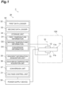
- the soil moisture sensor 1 includes a sensor unit 10 and a control unit 20.
- the sensor unit 10 is embedded in the soil 100.
- the control unit 20 is disposed outside the soil 100.
- the sensor unit 10 is electrically connected to the control unit 20 by a cable or the like.
- the sensor unit 10 includes a thermoelectric element 11 (temperature control unit), a first temperature measurement unit 12, and a second temperature measurement unit 13.
- An example of the thermoelectric element 11 is a Peltier element.
- the thermoelectric element 11 is electrically connected to the control unit 20 via a cable.
- the thermoelectric element 11 receives a predetermined voltage from the control unit 20. When a voltage is applied to the thermoelectric element 11, a temperature of one surface rises. When the voltage is applied to the thermoelectric element 11, a temperature of the other surface decreases.
- the two surfaces that operate differently from each other as described above are referred to as a first heat input/output surface 11a and a second heat input/output surface 11b.
- the thermoelectric element 11 has the first heat input/output surface 11a and the second heat input/output surface 11b.
- the first heat input/output surface 11a is a main surface.
- the second heat input/output surface 11b is a back surface. A portion of the soil 100 with which the first heat input/output surface 11a is in contact is different from another portion of the soil 100 with which the second heat input/output surface 11b is in contact.
- the thermoelectric element 11 can be switched between heating and cooling according to a polarity of an input voltage. According to the thermoelectric element 11, when the soil 100 is heated and/or cooled for measurement, a temperature of the soil 100 changes from an initial state. Therefore, a voltage having a polarity opposite to that at the time of measurement is applied to the thermoelectric element 11. A portion of the heated soil 100 is cooled. Another portion of the cooled soil 100 is heated. As a result, the temperature in the initial state can be quickly restored. An influence of the temperature of the soil 100 on crops can be suppressed.
- thermoelectric element 11 can alternately switch between a heating part and a cooling part.
- a positive current and a negative current are alternately applied to the thermoelectric element 11 for each measurement.
- a temperature of a measurement area rising greatly can be suppressed.
- a temperature of the measurement area decreasing greatly can also be suppressed.
- a cooling time of a probe after measurement is unnecessary. As a result, continuous measurement is made possible. Further, a moisture content can be measured without being affected by an ion concentration in water.
- the first temperature measurement unit 12 is fixed to the first heat input/output surface 11a.
- the first temperature measurement unit 12 obtains a temperature of the first heat input/output surface 11a. Therefore, the first temperature measurement unit 12 does not measure only the temperature of the soil 100 alone.
- the first temperature measurement unit 12 measures a temperature of a system including the thermoelectric element 11 and the soil 100 in contact with the thermoelectric element 11.
- the temperature of the first temperature measurement unit 12 includes effects of thermal properties such as a thermal capacity and thermal conductivity of the thermoelectric element 11 and, thermal properties of the soil 100. For example, as a factor affected by the thermal properties of the thermoelectric element 11, a time difference (time lag) from the start of application of electricity to the start of temperature rise can be exemplified.
- the soil 100 is in contact with the first heat input/output surface 11a. Further, the first temperature measurement unit 12 is also provided on the first heat input/output surface 11a. With such a configuration, a treatment of eliminating the influence caused by the thermal properties of the thermoelectric element 11 is possible.
- the first temperature measurement unit 12 is electrically connected to the control unit 20 via a cable.
- the first temperature measurement unit 12 outputs a signal on a temperature to the control unit 20.
- the second temperature measurement unit 13 is fixed to the second heat input/output surface 11b.
- the second temperature measurement unit 13 obtains a temperature of the second heat input/output surface 11b.
- the second temperature measurement unit 13 is electrically connected to the control unit 20 via a cable.
- the second temperature measurement unit 13 outputs a signal on a temperature to the control unit 20.
- the control unit 20 operates the sensor unit 10.
- the control unit 20 obtains a moisture content of the soil 100 by processing a signal transmitted from the sensor unit 10.
- the control unit 20 includes an arithmetic device 30 (arithmetic unit) and a power supply device 50 (power supply unit).
- the arithmetic device 30 outputs a control signal to the power supply device 50.
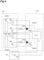
- the power supply device 50 includes a DC power supply 50a (see FIG. 4 ).
- the power supply device 50 outputs a voltage according to the control signal to the thermoelectric element 11. As a result, the thermoelectric element 11 operates.
- the power supply device 50 outputs a DC voltage to the thermoelectric element 11.
- the power supply device 50 can adjust a level of the voltage according to the control signal.
- the power supply device 50 can set a positive or negative polarity of the voltage according to the control signal. When positive and negative polarities of the voltage are reversed, for example, the first heat input/output surface, which has been a heating surface, can be switched to a cooling surface.
- the arithmetic device 30 receives a signal on a temperature from the first temperature measurement unit 12 and the second temperature measurement unit 13.
- the signal on a temperature may be, for example, a voltage signal.
- the arithmetic device 30 obtains a moisture content of the soil 100 using the voltage signal.
- FIG. 2 shows a temperature history obtained when the thermoelectric element 11 is operated to provide heat from the first heat input/output surface 11a to the soil 100 and dissipate heat of the soil 100 by the second heat input/output surface 11b.
- a graph G2a and a graph G2b are temperature histories obtained from the first temperature measurement unit 12.
- a graph G2c and a graph G2d are temperature histories obtained from the second temperature measurement unit 13.
- a moisture state of the soil 100 denoted by the graph G2a is different from a moisture state of the soil 100 denoted by the graph G2b. Specifically, a moisture content of the soil 100 denoted by the graph G2a is less than a moisture content of the soil 100 denoted by the graph G2b.
- temperatures of them during a steady state period S2 are different when the moisture states are different.
- a temperature difference that appears during the steady state period S2 is caused by a difference in thermal conductivity of the soil 100.
- the difference in thermal conductivity of the soil 100 is caused by a difference in moisture content. Therefore, the moisture content can be obtained using the temperature difference that appears during the steady state period S2.
- the inventors have found that a difference in thermal properties of the soil 100 caused by a difference in moisture content causes a difference in thermal conductivity and a difference in specific heat. Specifically, if a porosity of the soil 100 is constant, specific heat increases as a proportion of moisture increases. As a result, the thermal conductivity also increases. In thermal properties, a difference in specific heat appears in a temperature change amount per unit time.
- an "temperature change amount” is defined as a temperature change amount per unit time.
- the thermoelectric element 11 starts to provide heat, the temperature of the soil 100 in contact with the first heat input/output surface 11a rises.
- the temperature change amount per unit time appearing in the graph G2a is clearly different from the temperature change amount per unit time appearing in the graph G2b.
- the inventors have conceived that a moisture content can be obtained by using the temperature change amount per unit time.
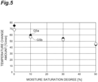
- FIG. 5 is an experiment result in which a temperature change amount was measured using a soil at a predetermined moisture saturation degree as a measurement object.
- the horizontal axis of the graph represents a moisture saturation degree. Soils with moisture saturation degrees of 0%, 10%, 30%, and 50% were used for the experiment.
- the vertical axis of the graph represents a temperature change amount.
- a plot G5a shown in FIG. 5 indicates a temperature history of a cooling side.
- a plot G5b indicates a temperature history on a heating side. As indicated by the plots G5a and G5b, it was found that a predetermined relationship could be read between the moisture saturation degree and the temperature change amount. Specifically, the temperature change amount decreased as the moisture saturation degree increased.
- the temperature change amount per unit time when the temperature of the soil 100 rises is the same as the temperature change amount per unit time when the temperature of the soil 100 decreases. Therefore, the moisture content can also be obtained using the temperature change amount when the temperature rises. The moisture content can also be obtained using the temperature change amount when the temperature decreases.
- the temperature change amount per unit time that appears during a transient period S1 has some advantages compared to the temperature change amount per unit time that appears during the steady state period S2.
- the difference in the temperature change amount per unit time is based on the difference in specific heat. Specific heat is less susceptible to factors such as an ion concentration of the soil 100. Since specific heat is less susceptible to noise, it is advantageous from the viewpoint of improving measurement accuracy.
- the transient period S1 arises.
- the steady state period S2 arises.
- the temperature change amount per unit time is obtained during the transient period S1.
- the temperature of the steady state period S2 is obtained during the steady state period S2.
- the temperature change amount per unit time obtained in the transient period S1 can be obtained at an earlier timing than that of the temperature in the steady state period S2. It is difficult to clearly determine whether or not the steady state period S2 has been reached. Compared to determining whether or not the steady state period S2 has been reached, it is easier to determine whether it is the transient period S1.
- the soil 100 that grows crops is managed under conditions suitable for growing the crops.
- the conditions suitable for growing crops include a moisture content, an ion concentration, and a temperature. It is desirable to cause the temperature of the soil 100 to fall within a predetermined range. Under such conditions, it is assumed that a temperature immediately after the start of the operation of the thermoelectric element 11 is a desired temperature. Then, the temperature in the transient period S1 deviates less from the desired temperature than the temperature in the steady state period S2. Therefore, an influence of measuring the moisture content on crops can be suppressed.
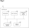
- FIG. 3 is a block diagram showing a hardware configuration of the arithmetic device 30.
- the arithmetic device 30 is a computer.
- the arithmetic device 30, which is a computer, physically includes one or more processors 30a, a storage device 30b such as a RAM (Random Access Memory) and a ROM (Read Only Memory), an input device 30c such as a keyboard, a display device 30d such as a display, and a communication device 30e serving as a communication interface for transmitting and receiving data.
- the arithmetic device 30 operates each hardware under the control of processor 30a by causing hardware such as the processor 30a to read a predetermined computer program.
- the arithmetic device 30 reads data from the storage device 30b.
- the arithmetic device 30 writes data to the storage device 30b. By these operations, each function of the arithmetic device 30 shown in FIG. 1 is realized.
- the arithmetic device 30 need not include all of these components.
- the arithmetic device 30 includes a voltage control unit 31, a first data logger 32, a second data logger 33, a storage unit 34, a gradient information acquisition unit 35, an equilibrium temperature acquisition unit 36, and a conversion unit 37.
- the voltage control unit 31 outputs a control signal to the power supply device 50.
- the control signal contains information such as a level of the voltage and a positive or negative polarity of the voltage.
- the first data logger 32 measures a voltage generated in the first temperature measurement unit 12.
- the first data logger 32 converts the voltage into temperature information.
- the first data logger 32 outputs the temperature information to the storage unit 34.
- the first data logger 32 includes a first voltmeter 32a, a first DC power supply 32b, and a first temperature converter 32c.
- the first voltmeter 32a measures a potential difference (voltage) generated in the first temperature measurement unit 12.
- the first voltmeter 32a outputs the voltage to the first temperature converter 32c.
- the first temperature converter 32c converts the voltage input from the first voltmeter 32a into a temperature.
- a relationship between the voltage and the temperature may be information acquired in advance.
- the relationship between the voltage and the temperature may have been stored in the storage unit 34.
- the information indicating the relationship between the voltage and the temperature may be a mathematical expression.
- the information indicating the relationship between the voltage and the temperature may be a conversion table.
- a configuration of the second data logger 33 is the same as that of the first data logger 32.
- the second data logger 33 also includes a second voltmeter 33a, a second DC power supply 33b, and a second temperature converter 33c. Operations of the second voltmeter 33a and the like are the same as those of the first voltmeter 32a and the like. Therefore, detailed description of the second voltmeter 33a, the second DC power supply 33b, and the second temperature converter 33c will be omitted.
- the first temperature measurement unit 12 and the first data logger 32 constitute a first temperature information acquisition unit M1.
- the second temperature measurement unit 13 and the second data logger 33 constitute a second temperature information acquisition unit M2.
- the first temperature measurement unit 12 includes a first diode 12a.
- a predetermined potential difference voltage
- the voltage generated between the input and output of the diode changes according to a temperature. For example, such a relationship that the temperature decreases as the voltage increases can be obtained by conducting a prior test. Therefore, a temperature can be obtained using the voltage. It is possible to know the temperature of the diode by measuring the voltage thereof.
- An input of the first diode 12a is connected to a positive electrode of the first DC power supply 32b via a first resistor 32d.
- the first resistor 32d is disposed between the first diode 12a and the first DC power supply 32b.
- An output of the first diode 12a is connected to a negative electrode of the first DC power supply 32b.
- the first voltmeter 32a is connected to the input of the first diode 12a and the output of the first diode 12a.
- the first voltmeter 32a outputs information on the voltage to the first temperature converter 32c.
- the conversion unit 37 converts the voltage into a temperature.
- the conversion unit 37 outputs temperature information.
- the second temperature measurement unit 13 also includes a second diode 13a.
- a connection configuration and an operation of the second diode 13a are the same as those of the first temperature information acquisition unit M1. Therefore, detailed description of the second temperature measurement unit 13 will be omitted.
- the storage unit 34 corresponds to the storage device 30b shown in FIG. 3 .
- the storage unit 34 receives first temperature information D1 from the first data logger 32.
- the storage unit 34 receives second temperature information D2 from the second data logger 33.
- the storage unit 34 is referred to by the gradient information acquisition unit 35.
- the storage unit 34 outputs the first temperature information D1 and the second temperature information D2 to the gradient information acquisition unit 35.
- the storage unit 34 is referred to by the conversion unit 37.
- the storage unit 34 outputs conversion information D3 to the storage unit 34.
- the storage unit 34 stores at least the first temperature information D1, the second temperature information D2, and the conversion information D3.
- the first temperature information D1 indicates a temporal change of a first temperature (for example, the graph G2a in FIG. 2 ).
- the first temperature information D1 is based on an output of the first temperature information acquisition unit M1.
- the second temperature information D2 indicates a temporal change of a second temperature (for example, the graph G2c in FIG. 2 ).
- the second temperature information D2 is based on an output of the second temperature information acquisition unit M2.
- the conversion information D3 is information for converting a gradient of the temperature change amount into the moisture content.
- the conversion information D3 may be a mathematical expression in which the gradient of the temperature change amount is used as an input variable and the moisture content is used as a dependent variable.
- the conversion information D3 may be a conversion table in which the moisture content corresponding to the gradient of the temperature change amount is summarized.
- the gradient information acquisition unit 35 acquires first gradient information using the first temperature information D1.
- first temperature information D1 There is no particular limitation on a specific content of processing for acquiring the first gradient information.
- the transient period S1 and the steady state period S2 are distinguished in the first temperature information D1 (graph G2a).
- a predetermined time width d1 (t2-t1) and a temperature difference d2 (T2a-T1a) occurring in the time width d1 are acquired.
- the time width d1 may be appropriately set on the basis of arbitrary conditions.
- a starting point for acquiring the gradient may be set in consideration of the time difference based on the thermal properties of the thermoelectric element 11 with a time point at which application of the current is started as a reference.
- the "starting point for acquiring the gradient" is, for example, a temperature T1a in FIG. 2 .
- a timing at which a change in temperature is detected may be set as the starting point for acquiring the gradient. It is not limited to the processing of obtaining the temperature difference d2 on the basis of the time width d1.
- the time width d1 may be obtained on the basis of the temperature difference d2.
- the first gradient information is obtained using the time width d1 and the temperature difference d2.
- the gradient information acquisition unit 35 performs the same processing.
- the gradient information acquisition unit 35 acquires the first gradient information and the second gradient information.
- the gradient information acquisition unit 35 may output the first gradient information and the second gradient information to the storage unit 34.
- the gradient information acquisition unit 35 may output the first gradient information and the second gradient information to the conversion unit 37.
- Information output by the gradient information acquisition unit 35 is not limited to the first gradient information and the second gradient information.
- the gradient information acquisition unit 35 may output a difference between the first gradient information and the second gradient information as total gradient information.
- the equilibrium temperature acquisition unit 36 acquires first equilibrium temperature information using the first temperature information D1. There is no particular limitation on a specific content of processing for acquiring the first equilibrium temperature information.
- the equilibrium temperature acquisition unit 36 acquires second equilibrium temperature information as a result of performing the same processing for the second temperature information D2.
- the equilibrium temperature acquisition unit 36 may be provided as necessary. It is also possible for the arithmetic device 30 to omit the equilibrium temperature acquisition unit 36.
- the conversion unit 37 converts the first gradient information into first moisture information.
- the conversion unit 37 converts the second gradient information into second moisture information.
- the conversion unit 37 receives the first gradient information from the gradient information acquisition unit 35 or the storage unit 34.
- the conversion unit 37 receives the conversion information D3 from the storage unit 34.
- the conversion unit 37 converts the first gradient information into the first moisture information by using the conversion information D3.
- the conversion unit 37 performs the same processing.
- the conversion unit 37 obtains total moisture information using the first moisture information and the second moisture information. There is no particular limitation on the processing of obtaining the total moisture information from the first moisture information and the second moisture information. For example, an average value of the first moisture information and the second moisture information may be used as the total moisture information.
- moisture content in the soil In the fields of agriculture and disaster prevention, it is important to measure a moisture content contained in the soil 100 (moisture content in the soil).
- a technology for measuring a moisture content in a soil there is a sensor employing a TDR method that utilizes reflection of electromagnetic waves.
- a sensor that employs a capacitance method that detects a difference in relative dielectric constant by measuring electrical impedance. All of these sensors measure a relative dielectric constant obtained from a combined capacitance of a substance. However, the relative dielectric constant is affected by a concentration of ions in water. In measuring the moisture content, differences in ion concentration result in noise.
- the soil moisture sensor 1 includes the thermoelectric element 11 disposed in the soil 100 and capable of changing a temperature of the soil 100, the first temperature information acquisition unit M1 acquiring the first temperature information D1 that indicates a temporal change in temperature of the soil 100 due to an operation of the thermoelectric element 11, a second temperature information acquisition unit M2 acquiring the second temperature information D2 that indicates a temporal change in temperature of the soil 100 due to an operation of the thermoelectric element 11, and an arithmetic device 30 obtaining moisture information on the basis of the temperature information.
- the arithmetic device 30 includes the gradient information acquisition unit 35 that acquires a temperature change amount per unit time using the first temperature information D1 and the second temperature information D2, and the conversion unit 37 that converts the temperature change amount into a moisture content using the conversion information D3 indicating a relationship between the temperature change amount and the moisture content.
- the soil moisture sensor 1 obtains a temperature change amount as information when it performs an operation of changing the temperature of the soil 100.
- the temperature change amount is related to information on moisture contained in the soil 100.
- the temperature change amount is based on specific heat of the soil 100.
- the specific heat of the soil 100 is a physical quantity. Therefore, the temperature change amount is less susceptible to a factor of a disturbance. Therefore, stable measurement results can be obtained by obtaining information on the moisture using the temperature change amount caused by specific heat.
- the soil moisture sensor 1 can obtain necessary measurement information in a short period of time. As a result, the measurement can be performed using only specific heat and thermal conductivity without generating Joule heat. According to this configuration, the moisture information can be measured without increasing an average temperature of the heating part and the cooling part.
- a sensor employing the TDR method that utilizes reflection of electromagnetic waves requires a signal with a high sampling frequency during measurement.
- the sensor employing the TDR method has a complicated and large system.
- the soil moisture sensor 1 of the first embodiment does not require a signal with a high sampling frequency as required in a device with the TDR method.
- the system can be simplified.
- the soil moisture sensor 1 can also be miniaturized. Therefore, the soil moisture sensor 1 can be suitably applied to precision agriculture in which compact sensors capable of wide-range and multi-point measurement are required.
- the embodiment of the present invention has been described above.
- the soil moisture sensor 1 of the present invention is not limited to the above-described embodiment.
- the soil moisture sensor 1 of the first embodiment is not limited to use in precision agriculture with a high nutrient concentration.
- it can be used for a soil with a high concentration of contamination and for calibrating a moisture content measurement sensor based on impedance.
- a measurement object is not limited to the soil 100.
- application to the field of skin regenerative medicine is also possible.
- it can be applied to a measurement of a moisture content under the high ion concentration such as physiological saline.
- the soil moisture sensor 1 that uses thermal properties of the measurement object may be applied to a multimodal sensor that measures a plurality of soil characteristic values such as a temperature, an ion concentration, and a pH value of the soil 100 in real time.
- the soil moisture sensor 1 may obtain the moisture content using only the temperature change amount per unit time or may obtain the moisture content by combining the temperature change amount per unit time and the temperature in a steady state.
- the first temperature measurement unit 12 does not necessarily have to be in direct contact with the first heat input/output surface 11a.
- the first temperature measurement unit 12 may be attached to the first heat input/output surface 11a via a member such as a heat transfer grease or an adhesive. Any member may be disposed between the first temperature measurement unit 12 and the first heat input/output surface 11a.
- the soil 100 which is a measurement object, may be present between the first temperature measurement unit 12 and the first heat input/output surface 11a.
- a gap may be present between the first temperature measurement unit 12 and the first heat input/output surface 11a. If the gap between the first temperature measurement unit 12 and the first heat input/output surface 11a is several centimeters (for example, 4 centimeters) or less, the same effects as the above-described soil moisture sensor 1 of the first embodiment can be obtained. The same applies to the relationship between the second temperature measurement unit 13 and the second heat input/output surface 11b.
- a soil moisture sensor according to a second embodiment will be described.
- the soil moisture sensor 1 described above utilized the fact that the moisture content contained in the soil 100 corresponded to the specific heat to measure the moisture content. Differences in specific heat corresponding to the moisture contents can be evaluated using various methods.
- the soil moisture sensor 1 of the first embodiment described above was evaluated using a degree of temperature rise (temperature change amount per unit time) when heat was applied to the soil 100. Then, the soil moisture sensor 1 of the first embodiment converted the temperature change amount per unit time into the moisture content.
- a soil moisture sensor 1A of the second embodiment also utilizes the fact that a moisture content contained in a soil 100 corresponds to specific heat to measure the moisture content.
- the soil moisture sensor 1A uses a method different from that of the soil moisture sensor 1 of the first embodiment to evaluate a difference in specific heat corresponding to the moisture content.
- the soil moisture sensor 1A will be described.
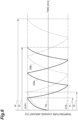
- the graph of FIG. 6 shows a temporal change of a temperature change amount of the soil 100.
- the horizontal axis of FIG. 6 represents an elapsed time with the start of heating due to a thermoelectric element 11 as a reference.
- the vertical axis in FIG. 6 represents a temperature change amount in the soil 100.
- the graph G6a shows a temporal change of a temperature change amount in the soil 100 with a low moisture content.
- the graph G6b shows a temporal change of a temperature change amount in the soil 100 with a high moisture content.
- the soil moisture sensor 1A repeats heating and cooling of the soil 100 a plurality of times.
- the soil moisture sensor 1A switches an operation of the thermoelectric element 11 from heating to cooling on condition that the temperature change amount of the soil 100 reaches a predetermined upper threshold value ⁇ 4H.
- the soil moisture sensor 1A switches the operation of the thermoelectric element 11 from cooling to heating on condition that the temperature change amount of the soil 100 reaches a predetermined lower threshold value ⁇ 4L.
- a moisture content contained in the soil 100 affects specific heat of the soil 100. Specifically, when the moisture content is low, the specific heat is low. Therefore, the soil 100 with a low moisture content has a large temperature change amount. For example, in a case of heating, a time t1 until reaching the upper threshold value ⁇ 4H is also short. On the other hand, when the moisture content is high, the specific heat is high. Therefore, the soil 100 with a high moisture content has a small temperature change amount. In a case of heating, a time t2 until reaching the upper threshold value ⁇ 4H is longer than the time t1.
- the difference in time until reaching the threshold value, that occurs according to the difference in moisture content, is integrated each time the operations of heating and cooling are repeated.
- times t3 and t4 until the given number of times of the predetermined switching operations is reached differ according to the moisture content contained in the soil 100.
- the time t4 until the given number of times is reached in a case in which the moisture content of the soil 100 is high (graph G6b) is longer than the time t3 until the given number of times is reached in a case in which the moisture content of the soil 100 is low (graph G6a). Therefore, the soil moisture sensor 1A evaluates a difference in specific heat corresponding to the moisture content using the times t3 and t4 until the given number of times of the switching operations is reached.
- the soil moisture sensor 1A includes a sensor unit 10 and a control unit 20A.
- the sensor unit 10 is the same as the sensor unit 10 of the soil moisture sensor 1 in the first embodiment. Therefore, detailed description of the sensor unit 10 will be omitted.
- the control unit 20A includes an arithmetic device 30A and a power supply device 50A.
- the arithmetic device 30A receives a first voltage ⁇ 1 output by a first temperature measurement unit 12.
- the arithmetic device 30A receives a second voltage ⁇ 1 output by a second temperature measurement unit 13.
- the arithmetic device 30A outputs a moisture content ⁇ 9 by using the first voltage ⁇ 1 and the second voltage ⁇ 1.
- the power supply device 50A provides either one of a first current ⁇ 1 and a second current ⁇ 2 to the thermoelectric element 11. A direction of the first current ⁇ 1 is opposite to a direction of the second current ⁇ 2.
- the power supply device 50A switches a direction of the current by switching a polarity of the voltage connected to the thermoelectric element 11.
- the power supply device 50A includes a switch 51, a switch 52, and a DC power supply 50s.
- the power supply device 50A switches a polarity of the DC power supply 53 connected to the thermoelectric element 11 by controlling the switch 51 and the switch 52. Terminals 53a and 53b connected to the switch 51 are switched according to control signals ⁇ 7a and ⁇ 8c.
- the switch 51 maintains connection to the terminal 53a or terminal 53b until it receives the next control signals ⁇ 7a and ⁇ 8c.
- Terminals 54a and 54b connected to the switch 52 are switched according to a control signal ⁇ 7b.
- the switch 52 maintains connection to the terminal 54a or terminal 54b until it receives the next control signal ⁇ 7b.
- the control signals ⁇ 7a, ⁇ 7b, and ⁇ 8c are provided from the arithmetic device 30A.
- a circuit configuration of the power supply device 50A shown in FIG. 7 is an example. Any circuit configuration may be employed as the circuit configuration of the power supply device 50A as long as it can switch a direction of the current supplied to the thermoelectric element 11.
- the arithmetic device 30A includes a first data logger 32A, a second data logger 33A, a storage unit 34A, and a moisture content acquisition unit 40A.
- the first data logger 32A receives the first voltage ⁇ 1.
- the first data logger 32A converts the first voltage ⁇ 1 into a first temperature change amount ⁇ 2.
- the first data logger 32A outputs the first temperature change amount ⁇ 2.
- the second data logger 33A receives the second voltage ⁇ 1.
- the second data logger 33A converts the second voltage ⁇ 1 into a second temperature change amount ⁇ 2.
- the second data logger 33A outputs the second temperature change amount ⁇ 2.
- first temperature change amount ⁇ 2 and the “second temperature change amount ⁇ 2" are each defined as a difference from a reference temperature TS when a temperature of the soil 100 immediately before the start of measurement is the reference temperature TS.
- the storage unit 34A receives the first temperature change amount ⁇ 2.
- the storage unit 34A stores the first temperature change amount ⁇ 2 in association with time.
- the storage unit 34A receives the second temperature change amount ⁇ 2.
- the storage unit 34A stores the second temperature change amount ⁇ 2 in association with time.
- the storage unit 34A has some values for processing of calculating the moisture content ⁇ 9.
- the storage unit 34A stores conversion information ⁇ 3 for converting an evaluation value into the moisture content ⁇ 9 as the value for the processing of calculating the moisture content ⁇ 9.
- the storage unit 34A has some values for controlling the sensor unit 10.
- the storage unit 34A stores a plurality of threshold values ⁇ 4 as the value for controlling the sensor unit 10.
- the storage unit 34A holds a specified number of times ⁇ 5 as the value for controlling the sensor unit 10.
- the "specified number of times ⁇ 5" is the number of switching performed in one measurement operation of the moisture content.
- the specified number of times ⁇ 5 may be defined as one switching from heating to cooling.
- the specified number of times ⁇ 5 may be defined as one switching from cooling to heating.
- one switching from heating to cooling and one switching from cooling to heating may be collectively defined as one switching of the specified number of times ⁇ 5.
- the moisture content acquisition unit 40A receives the first temperature change amount ⁇ 2 from the storage unit 34A.
- the moisture content acquisition unit 40A generates the control signals ⁇ 7a, ⁇ 7b, and ⁇ 8c for the power supply device 50A by using the first temperature change amount ⁇ 2.
- the moisture content acquisition unit 40A generates the moisture content ⁇ 9 by using the first temperature change amount ⁇ 2.
- the moisture content acquisition unit 40A includes a switching control unit 41A and a calculation processing unit 42A.
- the switching control unit 41A receives the first temperature change amount ⁇ 2 and the threshold values ⁇ 4 from the storage unit 34A.
- the switching control unit 41A generates the control signals ⁇ 7a, ⁇ 7b, and ⁇ 8c for the power supply device 50A using the first temperature change amount ⁇ 2 and the threshold values ⁇ 4.
- the calculation processing unit 42A receives an elapsed time ⁇ 8b from the switching control unit 41A. Further, the calculation processing unit 42A receives the conversion information ⁇ 3 from the storage unit 34A.
- the calculation processing unit 42A converts the elapsed time ⁇ 8b to the moisture content ⁇ 9 using the conversion information ⁇ 3.
- the switching control unit 41A includes a switching determination unit 41a, a switching instruction unit 41b, and a switching count unit 41c.
- the switching determination unit 41a receives the first temperature change amount ⁇ 2 from the storage unit 34A. Further, the switching determination unit 41a receives the threshold value ⁇ 4 from the storage unit 34A. The switching determination unit 41a determines whether or not the first temperature change amount ⁇ 2 has reached the threshold value ⁇ 4. The switching determination unit 41a outputs a determination result ⁇ 6 according to the determination result.
- the determination result ⁇ 6 is either information indicating that the first temperature change amount ⁇ 2 has reached the threshold value ⁇ 4 or information indicating that the first temperature change amount ⁇ 2 has not reached the threshold value ⁇ 4.
- the threshold values ⁇ 4 are conditions for alternately switching between heating and cooling of the thermoelectric element 11. There are some setting methods for the threshold values ⁇ 4. In the present embodiment, three setting methods are exemplified.
- a first setting method is utilized for control of only switching the first temperature change amount ⁇ 2.
- the second temperature change amount ⁇ 2 is not utilized for control of the switching.
- the graph G9a in FIG. 9(a) shows the first temperature change amount ⁇ 2.
- the first setting method employs two threshold values.
- the first setting method employs the upper threshold value ⁇ 4H and the lower threshold value ⁇ 4L.
- the upper threshold value ⁇ 4H is higher than, for example, the reference temperature TS of the soil 100 immediately before the start of measurement.
- the upper threshold value ⁇ 4H is higher than the reference temperature TS of the soil 100 immediately before the start of measurement by 4 degrees.
- the lower threshold value ⁇ 4L is lower than the reference temperature TS of the soil 100 immediately before the start of measurement.
- the lower threshold value ⁇ 4L is lower than the reference temperature TS of the soil 100 immediately before the start of measurement by 4 degrees.
- the temperature of the soil 100 with which a first heat input/output surface 11a is in contact can be reliably controlled. Specifically, the first temperature change amount ⁇ 2 of the soil 100 with which the first heat input/output surface 11a is in contact does not exceed the upper threshold value ⁇ 4H. Similarly, the first temperature change amount ⁇ 2 of the soil 100 with which the first heat input/output surface 11a is in contact does not exceed the lower threshold value ⁇ 4L.
- a second setting method is utilized for control of switching the first temperature change amount ⁇ 2 and the second temperature change amount ⁇ 2.
- the graph G9b in FIG. 9(b) shows the first temperature change amount ⁇ 2.
- the graph G9b in FIG. 9(b) shows the second temperature change amount ⁇ 2.
- the second setting method employs one upper threshold value ⁇ 4H.
- thermoelectric element 11 When the soil 100 is heated by the first heat input/output surface 11a of the thermoelectric element 11 and the first temperature change amount ⁇ 2 reaches the upper threshold value ⁇ 4H, the operation of the thermoelectric element 11 is switched (see a reference sign P1H). Due to the switching of the operation, heating of the soil 100 due to a second heat input/output surface 11b of the thermoelectric element 11 is started. That is, the second temperature change amount ⁇ 2 by the second temperature measurement unit 13 provided on the second heat input/output surface 11b starts to rise. Then, when the second temperature change amount ⁇ 2 reaches the upper threshold value ⁇ 4H, the operation of the thermoelectric element 11 is switched (see a reference sign P2H).
- the first temperature change amount ⁇ 2 of the soil 100 with which the first heat input/output surface 11a is in contact does not exceed the upper threshold value ⁇ 4H.
- the second temperature change amount ⁇ 2 of the soil 100 with which the second heat input/output surface 11b is in contact does not exceed the upper threshold value ⁇ 4H.
- the first temperature change amount ⁇ 2 and the second temperature change amount ⁇ 2 have been compared with the upper threshold value ⁇ 4H.
- the first temperature change amount ⁇ 2 and the second temperature change amount ⁇ 2 are compared with the lower threshold value ⁇ 4L as shown in FIG. 9(c) . That is, when the first temperature change amount ⁇ 2 reaches the lower threshold value ⁇ 4L (see a reference sign P1L), the operation of the thermoelectric element 11 is switched. Similarly, when the second temperature change amount ⁇ 2 reaches the lower threshold value ⁇ 4L (see a reference sign P2L), the operation of the thermoelectric element 11 is switched.
- the first temperature change amount ⁇ 2 of the soil 100 with which the first heat input/output surface 11a is in contact does not exceed the lower threshold value ⁇ 4L.
- the temperature ⁇ 2 of the soil 100 with which the second heat input/output surface 11b is in contact does not exceed the lower threshold value ⁇ 4L.
- FIG. 8 is referred to again.
- the switching instruction unit 41b receives the determination result ⁇ 6 from the switching determination unit 41a.
- the switching instruction unit 41b outputs the control signals ⁇ 7a and ⁇ 7b for switching a direction of the current to the power supply device 50A.
- the switching instruction unit 41b need not output any signal to maintain the direction of the current.
- the switching count unit 41c receives the determination result ⁇ 6 from the switching determination unit 41a.
- the switching count unit 41c updates a count value ⁇ 8a.
- the switching instruction unit 41b receives the determination result ⁇ 6 indicating that the threshold value ⁇ 4 has not been reached, the switching instruction unit 41b does not update the count value ⁇ 8a.
- the switching count unit 41c determines whether or not the count value ⁇ 8a of switching has reached the specified number of times ⁇ 5. When the count value ⁇ 8a of switching reaches the specified number of times ⁇ 5, the switching count unit 41c outputs the elapsed time ⁇ 8b until reaching the specified number of times ⁇ 5.
- the elapsed time ⁇ 8b is an evaluation value from which a difference in specific heat corresponding to the moisture content can be evaluated. Therefore, the elapsed time ⁇ 8b can be converted into the moisture content ⁇ 9. Further, when the count value ⁇ 8a of switching reaches the specified number of times ⁇ 5, the switching count unit 41c outputs the signal ⁇ 8c for stopping an output of the power supply device 50A.
- the calculation processing unit 42A includes a conversion unit 42a.
- the conversion unit 42a receives the elapsed time ⁇ 8b from the switching count unit 41c. Further, the conversion unit 42a receives the conversion information ⁇ 3 from the storage unit 34. The conversion unit 42a converts the elapsed time ⁇ 8b to the moisture content ⁇ 9 using the conversion information ⁇ 3. The conversion unit 42a outputs the moisture content ⁇ 9.
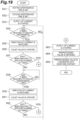
- FIG. 10 is a flowchart showing the operation of the soil moisture sensor 1A.
- the operation shown in FIG. 10 is a case in which the first setting method described above is employed.
- the threshold values ⁇ 4 are set (S11). For example, in S11, the upper threshold value ⁇ 4H and the lower threshold value ⁇ 4L are set. Next, the first temperature change amount ⁇ 2 is obtained (S12).
- the soil moisture sensor 1A can obtain stable measurement results.
- the soil moisture sensor 1A described above obtains the moisture content ⁇ 9 using the elapsed time ⁇ 8b obtained as a result of performing the switching operation a plurality of times.
- the result of performing the switching operation a plurality of times is used, it is possible to suppress an influence of variations in the time required for each heating or cooling.
- the switching control unit 41A further continues heating or cooling when the count value ⁇ 8a of switching is determined to have reached the specified number of times ⁇ 5. Then, the switching control unit 41A may stop supply of the current to the thermoelectric element 11 when the first temperature change amount ⁇ 2 is determined to have satisfied a predetermined condition.
- Such an operation may be performed by an end determination unit 41d shown in FIG.8 .
- the end determination unit 41d is an additional element and may be provided as necessary.
- the end determination unit 41d receives the first temperature change amount ⁇ 2.
- the end determination unit 41d outputs a signal ⁇ 10 for stopping an output of the current to the power supply device 50A when conditions are satisfied.
- the end determination unit 41d outputs a signal ⁇ 10 to the power supply device 50A to cause supply of the current to the thermoelectric element 11 to be stopped.
- "The case in which it can be determined that the first temperature change amount ⁇ 2 is zero" is not limited to a case in which the first temperature change amount ⁇ 2 is exactly zero.
- the end determination unit 41d is configured to set a predetermined allowable range with zero as a reference. Then, the end determination unit 41d may determine that the first temperature change amount ⁇ 2 is zero when it can be determined that the first temperature change amount ⁇ 2 is included within the allowable range.
- the soil moisture sensor 1A may be used in precision agriculture.
- roots of agricultural crops may be present in the soil 100 in the vicinity of the soil moisture sensor 1A.
- a temperature of the soil 100 affects a quality of agricultural crops. Therefore, when the soil moisture sensor 1A is used for precision agriculture, a difference between the temperature of the soil 100 before measurement and the temperature of the soil 100 after measurement is desired to be made small.
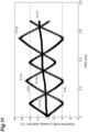
- FIG. 11 shows the first temperature change amount ⁇ 2 (graph G11a) and the second temperature change amount ⁇ 2 (graph G11b) in a case in which heating is switched to cooling when the first temperature change amount ⁇ 2 has reached the upper threshold value ⁇ 4H and a case in which cooling is switched to heating when the first temperature change amount ⁇ 2 has reached the lower threshold value ⁇ 4L.
- the graph G11a and the graph G11b are actual measured values.
- a graph G11c is a difference between the first temperature change amount ⁇ 2 and the second temperature change amount ⁇ 2. The difference indicates a temperature due to the Joule heat.
- first temperature change amount ⁇ 2 (graph G11a). Since the first temperature change amount ⁇ 2 is an object of control, it does not greatly deviate from the upper threshold value ⁇ 4H and the lower threshold value ⁇ 4L. On the other hand, the second temperature change amount ⁇ 2 (graph G11b) gradually increases in extreme values (see P11a and P11b in FIG. 11 ) during heating each time heating and cooling are repeated. As a result, the second temperature change amount ⁇ 2 may become higher than the upper threshold value ⁇ 4H.
- thermoelectric element 11 The phenomenon that the extreme values P11a and P11b of the second temperature change amount ⁇ 2 gradually increase can be explained by Joule heat generated by the thermoelectric element 11.
- thermoelectric element 11 heat based on the Peltier effect is released from the first heat input/output surface 11a. Further, when a current is supplied to the thermoelectric element 11, Joule heat based on the current is generated. The Joule heat is released from the first heat input/output surface 11a. That is, the first heat input/output surface 11a releases heat based on the Peltier effect, and Joule heat.
- thermoelectric element 11 when a current is supplied to the thermoelectric element 11, heat based on the Peltier effect is absorbed by the second heat input/output surface 11b. However, Joule heat is also released from the second heat input/output surface 11b. That is, a difference between the heat absorbed on the basis of the Peltier effect and the Joule heat is the heat actually absorbed by the second heat input/output surface 11b.
- the extreme value of the second temperature change amount ⁇ 2 which is not an object to be controlled, increases each time heating and cooling are repeated.
- the upper threshold value ⁇ 4H was a constant value. That is, the upper threshold value ⁇ 4H was one value. The same applies to the lower threshold value ⁇ 4L.
- the soil moisture sensor 1B employs a plurality of upper threshold values ⁇ 4Ha, ⁇ 4Hb, and ⁇ 4Hc different from each other. Further, the soil moisture sensor 1B employs a plurality of lower threshold values ⁇ 4La and ⁇ 4Lb different from each other.
- the soil moisture sensor 1B includes a sensor unit 10 and a control unit 20B.
- the sensor unit 10 is the same as the sensor unit 10 of the soil moisture sensor 1 in the first embodiment. Therefore, detailed description of the sensor unit 10 will be omitted.
- the control unit 20B includes an arithmetic device 30B and a power supply device 50B.
- the power supply device 50B is the same as the power supply device 50A of the soil moisture sensor 1A. Therefore, detailed description of the power supply device 50B will be omitted.
- the arithmetic device 30B includes a first data logger 32B, a second data logger 33B, a storage unit 34B, and a moisture content acquisition unit 40B.
- the first data logger 32B and the second data logger 33B are the same as the first data logger 32A and the second data logger 33A of the soil moisture sensor 1A. Therefore, detailed description of the first data logger 32B and the second data logger 33B will be omitted.
- the storage unit 34B stores a first temperature change amount ⁇ 2, a second temperature change amount ⁇ 2, conversion information ⁇ 3, and a specified number of times ⁇ 5.
- the storage unit 34B further stores a threshold value ⁇ 4B.
- the moisture content acquisition unit 40B includes a switching control unit 41B and a calculation processing unit 42B.
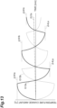
- the threshold value ⁇ 4B includes a plurality of upper threshold values ⁇ 4Ha, ⁇ 4Hb, and ⁇ 4Hc.
- three upper threshold values are exemplified, but the number of upper threshold values may be appropriately set according to the specified number of times ⁇ 5 of the switching operation.
- Information indicating that the upper threshold values ⁇ 4Ha, ⁇ 4Hb, and ⁇ 4Hc are each used for an n-th (n is an integer of 1 or more and N or less) heating operation is also contained in the reference signs.
- the upper threshold value ⁇ 4Ha is used for a first heating operation.
- the upper threshold value ⁇ 4Hb is used for a second heating operation.
- the upper threshold value ⁇ 4Hc is used for a third heating operation.
- the threshold values ⁇ 4B further includes a plurality of lower threshold values ⁇ 4La and ⁇ 4Lb.
- three lower threshold values are exemplified, but the number of lower threshold values may be appropriately set according to the specified number of times ⁇ 5 of the switching operation.
- Information indicating that the lower threshold values ⁇ 4La and ⁇ 4Lb are each used for an n-th (n is an integer of 1 or more and N or less) cooling operation is also contained in the reference signs.
- the lower threshold value ⁇ 4La is used for a first cooling operation.
- the lower threshold value ⁇ 4Lb is used for a second cooling operation.
- Heating and cooling are alternately performed. Therefore, the above-described five threshold values are used in an order of the upper threshold value ⁇ 4Ha, the lower threshold value ⁇ 4La, the upper threshold value ⁇ 4Hb, the lower threshold value ⁇ 4Lb, and the upper threshold value ⁇ 4Hc.
- threshold values are different can be rephrased as that absolute values of the threshold values are different.
- the above-described five threshold values are set so that the absolute values gradually decrease.
- an absolute value of the lower threshold value ⁇ 4La used after the upper threshold value ⁇ 4Ha is smaller than an absolute value of the upper threshold value ⁇ 4Ha. That is, in repeating heating and cooling, an absolute value of the threshold value used at the time of cooling is smaller than an absolute value of the threshold value that has been used for heating performed immediately before the cooling.
- the upper threshold value ⁇ 4Ha may, as an example, be +4 degrees
- the lower threshold value ⁇ 4La may, as an example, be -3 degrees.
- an absolute value of the upper threshold value ⁇ 4Hb used after the lower threshold value ⁇ 4La may be the same as the absolute value of the lower threshold value ⁇ 4La. That is, in repeating heating and cooling, an absolute value of the threshold value used at the time of heating may be set to be the same as an absolute value of the threshold value that has been used for cooling performed immediately before the heating.
- the lower threshold value ⁇ 4La may, as an example, be -3 degrees
- the upper threshold value ⁇ 4Hb may, as an example, be +3 degrees.
- the plurality of threshold values may be set as follows.
- the switching determination unit 41a determines whether or not to switch between heating and cooling using five threshold values and a count value ⁇ 8a.
- the count value ⁇ 8a may be used to control which of the five threshold values to use for the first temperature change amount ⁇ 2.
- Operations of a switching instruction unit 41b and a switching count unit 41c are the same as those of the second embodiment, and detailed description thereof will be omitted. Further, an operation of the calculation processing unit 42 is also the same as that of the second embodiment, and detailed description thereof will be omitted.
- FIG. 14 shows an operation flow of the soil moisture sensor 1B of the third embodiment.
- a difference from the operation flow of the second embodiment is that an operation of changing the threshold value (S15a, S21a) is added after the count value ⁇ 8a is updated (S15, S21). Since the other steps are the same as those in the operation flow of the second embodiment, detailed description thereof will be omitted.
- the above-described soil moisture sensor 1B can obtain stable measurement results.
- the soil moisture sensor 1B reduces the absolute value of the threshold value each time heating and cooling are repeated. As a result, the second temperature change amount ⁇ 2 of the second heat input/output surface 11b, which is not an object to be controlled, does not exceed the highest upper threshold value ⁇ 4Ha.
- the soil moisture sensor 1B reduces the absolute value of the threshold value each time heating and cooling are repeated. According to this operation, a time until reaching the threshold value is gradually shortened each time heating and cooling are repeated. As a result, an elapsed time ⁇ 8b until reaching the specified number of times ⁇ 5 can be shortened. Joule heat is proportional to a time during which a current flows. Therefore, a total amount of Joule heat generated by the thermoelectric element 11 during the measurement operation can be suppressed. Therefore, through the above-described two actions, the soil moisture sensor 1B can suitably maintain a temperature state of the soil 100 which is a measurement object.
- the switching control unit 41B further continues heating or cooling when the count value ⁇ 8a of switching is determined to have reached the specified number of times ⁇ 5. Then, the switching control unit 41B may stop supply of the current to the thermoelectric element 11 when the first temperature change amount ⁇ 2 and the second temperature change amount ⁇ 2 are determined to have satisfied a predetermined condition.
- Such an operation may be performed by the end determination unit 41d shown in FIG. 12 .
- the end determination unit 41d receives the first temperature change amount ⁇ 2 and the second temperature change amount ⁇ 2. For example, in a case in which the first temperature change amount ⁇ 2 and the second temperature change amount ⁇ 2 have been determined to coincide with each other, the end determination unit 41d outputs a signal ⁇ 10, which causes supply of the current to the thermoelectric element 11 to be stopped, to the power supply device 50B.
- a signal ⁇ 10 which causes supply of the current to the thermoelectric element 11 to be stopped
- the end determination unit 41d obtains a difference between the first temperature change amount ⁇ 2 and the second temperature change amount ⁇ 2. "The case in which the first temperature change amount ⁇ 2 and the second temperature change amount ⁇ 2 exactly coincide with each other" is that the difference is zero. When the difference is zero, the first temperature change amount ⁇ 2 and the second temperature change amount ⁇ 2 may be determined to coincide with each other. Further, the end determination unit 41d is configured to set a predetermined allowable range with zero as a reference.
- the end determination unit 41d may determine that the first temperature change amount ⁇ 2 and the second temperature change amount ⁇ 2 have coincided with each other.
- thermoelectric element An absolute value of a voltage applied to the thermoelectric element: 1.3 V.
- Measurement object simulated soil with the moisture content of 0%.
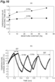
- FIG. 15(a) shows temperature histories of the first temperature change amount ⁇ 2 and the second temperature change amount ⁇ 2.
- the horizontal axis represents a measurement time.
- the vertical axis represents a temperature change amount from the reference temperature TS.
- a graph G15a indicates the first temperature change amount ⁇ 2.
- a graph G15b indicates the second temperature change amount ⁇ 2.
- the graph G15a and the graph G15b are actual measured values.
- a graph G15c indicates a temperature due to the Joule heat.
- the temperature due to the Joule heat is the difference between the first temperature change amount ⁇ 2 and the second temperature change amount ⁇ 2. Therefore, the graph G15c is a calculated value.
- the first temperature change amount ⁇ 2 (graph G15a) is an object to be controlled. Therefore, the first temperature change amount ⁇ 2 (graph G15a) did not exceed the upper threshold value ⁇ 4Ha.
- the second temperature change amount ⁇ 2 (graph G15b) is not an object to be controlled. However, the second temperature change amount ⁇ 2 also did not exceed the upper threshold value ⁇ 4Ha by changing the threshold value. Therefore, it was found that the soil moisture sensor 1B could control so that the temperature change amount, which is not an object to be controlled, did not deviate from the threshold value.
- thermoelectric element An absolute value of a voltage applied to the thermoelectric element: 1.3 V.
- thermoelectric element An absolute value of a voltage applied to the thermoelectric element: 3V.
- the horizontal axis of the graph in FIG. 15(b) represents a moisture content.
- the vertical axis of the graph in FIG. 15(b) represents a temperature TJ increased due to the Joule heat.
- a graph G15d shows results of experimental example 2.
- a graph G15e shows results of the comparative example.
- the horizontal axis of FIG. 16(a) represents a moisture content.
- the vertical axis of FIG. 16(b) represents a time until a threshold value is reached.
- the "time until the threshold value is reached” is, in other words, the elapsed time ⁇ 8b.
- the horizontal axis of FIG. 16(b) represents a measurement time.
- the vertical axis of FIG. 16(b) represents a temperature change amount.
- a graph G16c is a history of a temperature change amount in the simulated soil with the moisture content of 0%.
- a graph G16d is a history of a temperature change amount in the simulated soil with the moisture content of 50%.
- the soil moisture sensor 1A of the second embodiment employed temperature as the switching condition for alternately switching between heating and cooling. Then, the soil moisture sensor 1A obtained the moisture content by using the time required for switching between heating and cooling a specified number of times.
- a soil moisture sensor 1C of a fourth embodiment employs time as a switching condition. Then, the soil moisture sensor 1C obtains a moisture content by using extreme values of temperature caused by heating and cooling.
- the soil moisture sensor 1C includes a sensor unit 10 and a control unit 20C.
- the sensor unit 10 is the same as the sensor unit 10 of the soil moisture sensor 1 in the first embodiment. Therefore, detailed description of the sensor unit 10 will be omitted.
- the control unit 20C includes an arithmetic device 30C and a power supply device 50C.
- the power supply device 50C is the same as the power supply device 50A of the soil moisture sensor 1A. Therefore, detailed description of the power supply device 50C will be omitted.
- the arithmetic device 30C includes a first data logger 32C, a second data logger 33C, a storage unit 34C, and a moisture content acquisition unit 40C.
- the first data logger 32C and the second data logger 33C are the same as the first data logger 32A and the second data logger 33A of the soil moisture sensor 1A. Therefore, detailed description of the first data logger 32C and the second data logger 33C will be omitted.
- the storage unit 34C stores a first temperature change amount ⁇ 2, a second temperature change amount ⁇ 2, conversion information ⁇ 3C, and a specified number of times ⁇ 5.
- the storage unit 34B further stores a switching time ⁇ 4C.
- the switching time ⁇ 4C includes a heating maintenance time ⁇ 4Ca and a cooling maintenance time ⁇ 4Cb.
- the "heating maintenance time ⁇ 4Ca” is assumed to be a heating time at a second heat input/output surface 11b.
- the "cooling maintenance time ⁇ 4Cb" is assumed to be a cooling time at the second heat input/output surface 11b.
- the "heating maintenance time ⁇ 4Ca” is a cooling maintenance time from the viewpoint of the first heat input/output surface 11a.
- the "cooling maintenance time ⁇ 4Cb” is a heating maintenance time from the viewpoint of the first heat input/output surface 11a.
- the soil moisture sensor 1C converts a temperature change amount into a moisture content.
- the conversion information ⁇ 3C includes information for converting the temperature change amount into the moisture content.
- the conversion information ⁇ 3C may be, for example, a function in which the temperature change amount is used as an independent variable and the moisture content is used as a dependent variable.
- the soil moisture sensor 1C starts heating of the second heat input/output surface 11b and then switches to cooling when the heating maintenance time ⁇ 4Ca has elapsed.
- the soil moisture sensor 1C starts cooling of the second heat input/output surface 11b and then switches to heating when the cooling maintenance time ⁇ 4Cb has elapsed.
- the moisture content acquisition unit 40C includes a switching control unit 41C and a calculation processing unit 42C.
- the switching control unit 41C obtains control signals ⁇ 7a and ⁇ 7b to be provided to the power supply device 50C by using the heating maintenance time ⁇ 4Ca and the cooling maintenance time ⁇ 4Cb.
- the calculation processing unit 42C obtains a moisture content ⁇ 9 by using the first temperature change amount ⁇ 2 or the second temperature change amount ⁇ 2.
- a switching determination unit 41a of the switching control unit 41C receives the heating maintenance time ⁇ 4Ca and the cooling maintenance time ⁇ 4Cb.
- the switching determination unit 41a determines whether or not an elapsed time has reached the heating maintenance time ⁇ 4Ca at a predetermined timing during execution of the heating operation of the second heat input/output surface 11b.
- the switching determination unit 41a determines whether or not an elapsed time has reached the cooling maintenance time ⁇ 4Cb at a predetermined timing during execution of the cooling operation of the second heat input/output surface 11b.
- the switching determination unit 41a outputs a determination result ⁇ 6 when the elapsed time reaches the heating maintenance time ⁇ 4Ca or when the elapsed time reaches the cooling maintenance time ⁇ 4Cb.
- the switching instruction unit 41b and the switching count unit 41c are the same as those in the second embodiment, and detailed description thereof will be omitted. Further, the soil moisture sensor 1C does not utilize the elapsed time ⁇ 8b to obtain the moisture content. Therefore, the switching count unit 41c of the soil moisture sensor 1C may not output the elapsed time ⁇ 8b.
- the calculation processing unit 42C includes a preprocessing unit 42s and a conversion unit 42a.
- the preprocessing unit 42s receives the first temperature change amount ⁇ 2.
- the preprocessing unit 42s obtains a preprocessed value ⁇ 2s using the first temperature change amount ⁇ 2.
- the preprocessing unit 42s outputs the preprocessed value ⁇ 2s to the conversion unit 42a.
- the conversion unit 42a receives the preprocessed value ⁇ 2s and the conversion information ⁇ 3C.
- the conversion unit 42a converts the preprocessed value ⁇ 2s into the moisture content ⁇ 9 using the conversion information ⁇ 3C.
- the preprocessed value ⁇ 2s is a temperature change amount.
- FIG. 18 shows a temporal change of the temperature change amount when heating and cooling are switched each time a certain period of time elapses.
- the horizontal axis of FIG. 18 represents a time.
- the vertical axis of FIG. 18 represents a temperature change amount.
- a graph G18a indicates the first temperature change amount ⁇ 2.
- a graph G18b indicates the second temperature change amount ⁇ 2.
- the extreme values P18a and P18c of the graph G18a are temperatures of the first heat input/output surface 11a.
- the extreme value P18b of the graph G18b is a temperature of the second heat input/output surface 11b.
- a highest extreme value P18c may be used as the preprocessed value ⁇ 2s.
- a total value obtained by summing all the extreme values P18a, P18b, and P18c may be used as the preprocessed value ⁇ 2s.
- an average value of the extreme values P18a, P18b, and P18c may be used as the preprocessed value ⁇ 2s.
- the preprocessed value ⁇ 2s may be a value based on extreme values P18d, P18e, and P18f on a low temperature side present in the graph G18a and the graph G18b.
- the extreme value P18e of the graph G18a is a temperature of the first heat input/output surface 11a.
- the extreme values P18d and P18f of the graph G18b are temperatures of the second heat input/output surface 11b.
- a lowest extreme value P18d may be used as the preprocessed value ⁇ 2s.
- a total value obtained by summing all the extreme values P18d, P18e, and P18f may be used as the preprocessed value ⁇ 2s. Further, an average value of the extreme values P18d, P18e, and P18f may be used as the preprocessed value ⁇ 2s.
- the preprocessed value ⁇ 2s may be a value obtained as a difference between the first temperature change amount ⁇ 2 and the second temperature change amount ⁇ 2.
- the difference is indicated as a graph G18c.
- FIG. 19 shows an operation flow of the soil moisture sensor 1C of the fourth embodiment.
- the heating maintenance time ⁇ 4Ca is set(S51).
- a cooling maintenance time ⁇ 4Cb is set (S52).
- supply of a current is started (S53). Counting of an elapsed heating time is also started at the same time as supply of the current is started.
- S54 it is determined whether or not the elapsed heating time has reached the heating maintenance time ⁇ 4Ca (S54). If the elapsed heating time is determined to have not reached the heating maintenance time ⁇ 4Ca (S54: NO), S54 is executed again after elapse of a predetermined time. If the elapsed heating time is determined to have reached the heating maintenance time ⁇ 4Ca (S54: YES), a direction of the current is switched (S55). When the direction of the current is switched, counting of an elapsed cooling time starts as a new elapsed time. Next, the count value ⁇ 8a of switching is updated (S56). Next, it is determined whether or not the number of times of switching has reached the specified number of times ⁇ 5 (S57). If the number of times of switching is determined to have reached the specified number of times ⁇ 5 (S57: YES), the processing proceeds to processing of obtaining the moisture content (S63, S64, S65).
- the count value ⁇ 8a of switching is updated (S61).
- an end determination unit 41d may end the measurement on condition that the first temperature change amount ⁇ 2 coincides with the second temperature change amount ⁇ 2 as indicated by the point P18g in FIG. 18 .
- the first temperature change amount ⁇ 2 coinciding with the second temperature change amount ⁇ 2 does not require an exact coincidence.
- the above-described soil moisture sensor 1C can obtain stable measurement results by obtaining information on the moisture using the temperature change amount caused by specific heat.
- the soil moisture sensor 1C switches between heating and cooling each time a predetermined time elapses.
- the first temperature change amount ⁇ 2 and the second temperature change amount ⁇ 2 (see FIG. 18 ) obtained by the operation can remove an influence of temperature due to the Joule heat by correction.
- the extreme values P18a, P18b, and P18c included in the graph G18a of FIG. 18 rise substantially linearly with the elapse of time. This rise is predicted to be due to an influence of the Joule heat. Therefore, an approximate straight line connecting the extreme values P18a, P18b, and P18c is set. Then, a function representing the approximate straight line is obtained.
- the first temperature change amount ⁇ 2 is corrected using the function, it is possible to obtain information on a temperature history from which an influence of the Joule heat has been removed.
Landscapes
- Life Sciences & Earth Sciences (AREA)
- Health & Medical Sciences (AREA)
- Engineering & Computer Science (AREA)
- Chemical & Material Sciences (AREA)
- Immunology (AREA)
- Analytical Chemistry (AREA)
- Pathology (AREA)
- General Physics & Mathematics (AREA)
- General Health & Medical Sciences (AREA)
- Biochemistry (AREA)
- Physics & Mathematics (AREA)
- Soil Sciences (AREA)
- Water Supply & Treatment (AREA)
- Environmental Sciences (AREA)
- Medicinal Chemistry (AREA)
- Food Science & Technology (AREA)
- General Life Sciences & Earth Sciences (AREA)
- Environmental & Geological Engineering (AREA)
- Geology (AREA)
- Remote Sensing (AREA)
- Investigating Or Analyzing Materials Using Thermal Means (AREA)
- Investigating Or Analyzing Materials By The Use Of Electric Means (AREA)
Abstract
Description
- The present invention relates to a moisture sensor which obtains information on moisture contained in a measurement subject.
- In the field of agriculture, decrease in the number of farmers and the aging of farmers are regarded as problems. Precision agriculture has been studied as a technology for growing high-quality crops without relying on experience of farmers. In precision agriculture, various sensors are used to measure a condition of soil in which crops are grown. When a result of measuring the soil condition is utilized, it becomes possible to obtain an optimum moisture content and soil composition for crops.
- Non-Patent Literature 1 discloses a technology related to a soil moisture sensor. In the soil moisture sensor of Non-Patent
Literature 1, a probe for measurement is disposed in a soil. The probe of Non-PatentLiterature 1 includes a case formed of a porous material and a transistor accommodated in the case. - [Non-Patent Literature 1] Pedro Carvalhaes Dias et al., "Proposal of a Novel Heat Dissipation Soil Moisture Sensor," IEEE Recent Researches in Circuits, Systems and Signal Processing, July 2011, pp. 124-127.
- As indicators representing soil conditions, for example, an ion concentration, a moisture content, pH, a temperature, and the like can be mentioned. For example, a TDR method and a capacitance method have been studied as technologies for obtaining a moisture content. The TDR method utilizes reflection of electromagnetic waves. The capacitance method utilizes electrical impedance and a relative dielectric constant. In the TDR method and the capacitance method, a moisture content is obtained by utilizing a relative dielectric constant based on a combined capacitance of a measurement object. The relative dielectric constant is affected by a concentration of ions contained in water. Therefore, even if the moisture content is the same, measured values may vary due to an influence of the ion concentration.
- An objective of the present invention is to provide a moisture sensor capable of obtaining stable measurement results.
- One embodiment of the present invention is a moisture sensor which obtains moisture information on moisture contained in a measurement object. The moisture sensor includes a temperature control unit disposed in the measurement object and being able to change a temperature of the measurement object, a temperature information acquisition unit acquiring temperature information indicating a temporal change of the temperature of the measurement object due to an operation of the temperature control unit, and an arithmetic unit obtaining the moisture information on the basis of the temperature information. The arithmetic unit includes a gradient information acquisition unit acquiring a temperature change amount per unit time by utilizing the temperature information, and a conversion unit converting the temperature change amount into the moisture information by utilizing conversion information indicating a relationship between the temperature change amount and the moisture information.
- The moisture sensor obtains a temperature change amount when it performs an operation of changing a temperature of the measurement object. The temperature change amount is related to information on moisture contained in the measurement object. The temperature change amount is based on specific heat of the measurement object. The specific heat of the measurement object is a physical quantity. The specific heat, which is a physical quantity, is less susceptible to a disturbance. Therefore, stable measurement results can be obtained by obtaining information on the moisture by utilizing the temperature change amount caused by specific heat.
- The temperature control unit of the moisture sensor of one embodiment may be a thermoelectric element which converts electrical energy into thermal energy. The thermoelectric element can switch between heating and cooling by switching between positive and negative polarities of a voltage. According to this characteristic, the temperature of the measurement object can be kept within a predetermined range.
- The thermoelectric element of the moisture sensor of one embodiment may include a first heat input/output surface and a second heat input/output surface which are in contact with the measurement object and configured to provide heat to the measurement object and dissipate heat from the measurement object. The temperature information acquisition unit may include a first temperature measurement unit attached to the first heat input/output surface, and a second temperature measurement unit attached to the second heat input/output surface. According to this configuration, it is possible to obtain the temperature change amount based on two different aspects. As a result, more stable measurement results can be obtained.
- In the moisture sensor of one embodiment, the thermoelectric element may be able to perform an operation of providing heat to the measurement object from one of the first heat input/output surface and the second heat input/output surface, and dissipating heat from the measurement object by the other of the first heat input/output surface and the second heat input/output surface. The gradient information acquisition unit may acquire a first temperature change amount by utilizing first temperature information obtained from the first temperature measurement unit and may acquire a second temperature change amount by utilizing second temperature information obtained from the second temperature measurement unit. The conversion unit may obtain the moisture information by utilizing the conversion information, the first temperature change amount, and the second temperature change amount. According to this configuration, it is possible to improve an accuracy of measurement results.
- In the moisture sensor of one embodiment, the gradient information acquisition unit may acquire the temperature change amount using a difference between a first temperature and a second temperature during a transient period in a change of the temperature of the measurement object over time.
- In the moisture sensor of one embodiment, the temperature information acquisition unit may be disposed to be in contact with the measurement object.
- A moisture sensor, which is another embodiment of the present invention, obtains moisture information on moisture contained in a measurement object. The moisture sensor of another embodiment includes a thermoelectric element disposed in the measurement object and being able to change a temperature of the measurement object, a power supply unit supplying a current to the thermoelectric element and being able to switch a direction of the current supplied to the thermoelectric element, a temperature information acquisition unit acquiring the temperature of the measurement object, and a moisture content acquisition unit controlling a direction of the current supplied to the thermoelectric element from the power supply unit and acquiring the moisture information by utilizing the temperature acquired by the temperature information acquisition unit.
- In the moisture sensor of another embodiment, the moisture content acquisition unit may include a switching control unit which controls a direction of the current supplied to the thermoelectric element from the power supply unit by utilizing the temperature of the measurement object.
- In the moisture sensor of another embodiment, the switching control unit may perform a switching operation of switching a direction of the current supplied to the thermoelectric element from the power supply unit when the temperature of the measurement object has reached at least one predetermined threshold value.
- In the moisture sensor of another embodiment, the switching control unit may perform the switching operation N times (N is an integer of 1 or more). The moisture content acquisition unit may acquire the moisture information using an elapsed time required for the switching operation of N times.
- In the moisture sensor of another embodiment, the switching control unit may control a direction of the current supplied to the thermoelectric element from the power supply unit by utilizing one predetermined threshold value.
- In the moisture sensor of another embodiment, the switching control unit may control a direction of the current supplied to the thermoelectric element from the power supply unit by utilizing a plurality of predetermined threshold values different from each other.
- In the moisture sensor of another embodiment, an absolute value of the threshold value utilized when the measurement object is cooled may be smaller than an absolute value of the threshold value utilized when the measurement object is heated.
- In the moisture sensor of another embodiment, the thermoelectric element may include a first heat input/output surface and a second heat input/output surface which are in contact with the measurement object and configured to provide heat to the measurement object and dissipate heat from the measurement object. The temperature information acquisition unit may include a first temperature measurement unit attached to the first heat input/output surface. The plurality of threshold values may include one or more upper threshold values higher than the temperature of the measurement object before a start of measurement and one or more lower threshold values lower than the temperature of the measurement object before the start of measurement. The switching control unit may switch a direction of the current when a temperature acquired by the first temperature measurement unit has reached the upper threshold value or the lower threshold value.
- In the moisture sensor of another embodiment, the thermoelectric element may include a first heat input/output surface and a second heat input/output surface which are in contact with the measurement object and configured to provide heat to the measurement object and dissipate heat from the measurement object. The temperature information acquisition unit may include a first temperature measurement unit attached to the first heat input/output surface, and a second temperature measurement unit attached to the second heat input/output surface. The plurality of threshold values may include one or more upper threshold values higher than the temperature of the measurement object before a start of measurement. The switching control unit may switch a direction of the current when a temperature acquired by the first temperature measurement unit has reached the upper threshold value or when a temperature acquired by the second temperature measurement unit has reached the upper threshold value.
- In the moisture sensor of another embodiment, the temperature information acquisition unit may acquire the temperature of the measurement object before the start of measurement as a reference temperature. The switching control unit may stop supply of a current from the power supply unit to the thermoelectric element when the temperature acquired by the first temperature measurement unit is determined to have reached the reference temperature during supply of the current from the power supply unit to the thermoelectric element.
- In the moisture sensor of another embodiment, the thermoelectric element may include a first heat input/output surface and a second heat input/output surface which are in contact with the measurement object and configured to provide heat to the measurement object and dissipate heat from the measurement object. The temperature information acquisition unit may include a first temperature measurement unit attached to the first heat input/output surface, and a second temperature measurement unit attached to the second heat input/output surface on a side opposite to the first heat input/output surface. The plurality of threshold values may include one or more lower threshold values lower than the temperature of the measurement object before the start of measurement. The switching control unit may switch a direction of the current when a temperature acquired by the first temperature measurement unit has reached the lower threshold value or when a temperature acquired by the second temperature measurement unit has reached the lower threshold value.
- In the moisture sensor of another embodiment, the switching control unit may stop supply of the current from the power supply unit to the thermoelectric element when the temperature acquired by the first temperature measurement unit and the temperature acquired by the second temperature measurement unit are determined to coincide with each other.
- In the moisture sensor of another embodiment, the moisture content acquisition unit may include a switching control unit which controls a direction of the current supplied to the thermoelectric element from the power supply unit each time a predetermined switching time elapses.
- In the moisture sensor of another embodiment, the moisture content acquisition unit may acquire the moisture information by utilizing at least one extreme value of the temperature of the measurement object.
- In the moisture sensor of another embodiment, the thermoelectric element may include a first heat input/output surface and a second heat input/output surface which are in contact with the measurement object and configured to provide heat to the measurement object and dissipate heat from the measurement object. The temperature information acquisition unit may include a first temperature measurement unit attached to the first heat input/output surface, and a second temperature measurement unit attached to the second heat input/output surface. The switching control unit may stop supply of the current from the power supply unit to the thermoelectric element when a temperature acquired by the first temperature measurement unit and a temperature acquired by the second temperature measurement unit are determined to coincide with each other.
- According to the present invention, a moisture sensor capable of obtaining stable measurement results is provided.
-
-
FIG. 1 is a diagram schematically showing a configuration of a moisture sensor of a first embodiment. -
FIG. 2 is a diagram for explaining a principle of obtaining a moisture content. -
FIG. 3 is a diagram showing an example of a physical configuration of an arithmetic device. -
FIG. 4 is a diagram showing an example of an electrical configuration of a temperature acquisition unit included in the moisture sensor ofFIG. 1 . -
FIG. 5 is a graph showing an example of a relationship between a moisture saturation degree and a temperature change amount. -
FIG. 6 is a diagram for explaining a principle of measurement employed by a moisture sensor of a second embodiment. -
FIG. 7 is a diagram schematically showing a configuration of the moisture sensor of the second embodiment. -
FIG. 8 is a diagram showing a configuration of the moisture sensor shown inFIG. 7 in detail. -
FIG. 9(a) is a diagram showing a first setting method for a threshold value.FIG. 9(b) is a diagram showing a second setting method for a threshold value.FIG. 9(c) is a diagram showing a third setting method for a threshold value. -
FIG. 10 is a flowchart showing an operation of the moisture sensor shown inFIG. 7 . -
FIG. 11 shows histories of a first temperature and a second temperature when the threshold value is made constant. -
FIG. 12 is a diagram showing a configuration of a moisture sensor of a third embodiment in detail. -
FIG. 13 shows histories of a first temperature and a second temperature when the threshold value is made variable. -
FIG. 14 is a flowchart showing an operation of the moisture sensor shown inFIG. 12 . -
FIG. 15(a) is a graph showing a result of experimental example 1.FIG. 15(b) is a graph showing a result of experimental example 2. -
FIG. 16(a) is a graph showing a result of experimental example 3.FIG. 16(b) is a graph showing a result of experimental example 4. -
FIG. 17 is a diagram showing a configuration of a moisture sensor of a fourth embodiment in detail. -
FIG. 18 shows histories of a first temperature and a second temperature obtained by an operation of switching between heating and cooling at predetermined times. -
FIG. 19 is a flowchart showing an operation of the moisture sensor shown inFIG. 17 . - Hereinafter, embodiments for implementing the present invention will be described in detail with reference to the accompanying drawings. In the description of the drawings, the same elements will be denoted by the same reference signs, and duplicate description thereof will be omitted.
- As shown in
FIG. 1 , a moisture sensor obtains a moisture content contained in a measurement object. In a first embodiment, asoil 100 is exemplified as the measurement object. In the following description, the moisture sensor is referred to as asoil moisture sensor 1. Thesoil moisture sensor 1 includes asensor unit 10 and acontrol unit 20. Thesensor unit 10 is embedded in thesoil 100. Thecontrol unit 20 is disposed outside thesoil 100. Thesensor unit 10 is electrically connected to thecontrol unit 20 by a cable or the like. - The
sensor unit 10 includes a thermoelectric element 11 (temperature control unit), a firsttemperature measurement unit 12, and a secondtemperature measurement unit 13. An example of thethermoelectric element 11 is a Peltier element. Thethermoelectric element 11 is electrically connected to thecontrol unit 20 via a cable. Thethermoelectric element 11 receives a predetermined voltage from thecontrol unit 20. When a voltage is applied to thethermoelectric element 11, a temperature of one surface rises. When the voltage is applied to thethermoelectric element 11, a temperature of the other surface decreases. The two surfaces that operate differently from each other as described above are referred to as a first heat input/output surface 11a and a second heat input/output surface 11b. - The
thermoelectric element 11 has the first heat input/output surface 11a and the second heat input/output surface 11b. When thethermoelectric element 11 has a flat plate shape, the first heat input/output surface 11a is a main surface. The second heat input/output surface 11b is a back surface. A portion of thesoil 100 with which the first heat input/output surface 11a is in contact is different from another portion of thesoil 100 with which the second heat input/output surface 11b is in contact. - The
thermoelectric element 11 can be switched between heating and cooling according to a polarity of an input voltage. According to thethermoelectric element 11, when thesoil 100 is heated and/or cooled for measurement, a temperature of thesoil 100 changes from an initial state. Therefore, a voltage having a polarity opposite to that at the time of measurement is applied to thethermoelectric element 11. A portion of theheated soil 100 is cooled. Another portion of the cooledsoil 100 is heated. As a result, the temperature in the initial state can be quickly restored. An influence of the temperature of thesoil 100 on crops can be suppressed. - In other words, the
thermoelectric element 11 can alternately switch between a heating part and a cooling part. In order to exhibit a function of alternately switching between the heating part and the cooling part, a positive current and a negative current are alternately applied to thethermoelectric element 11 for each measurement. As a result, a temperature of a measurement area rising greatly can be suppressed. Further, a temperature of the measurement area decreasing greatly can also be suppressed. Moreover, a cooling time of a probe after measurement is unnecessary. As a result, continuous measurement is made possible. Further, a moisture content can be measured without being affected by an ion concentration in water. - The first
temperature measurement unit 12 is fixed to the first heat input/output surface 11a. The firsttemperature measurement unit 12 obtains a temperature of the first heat input/output surface 11a. Therefore, the firsttemperature measurement unit 12 does not measure only the temperature of thesoil 100 alone. The firsttemperature measurement unit 12 measures a temperature of a system including thethermoelectric element 11 and thesoil 100 in contact with thethermoelectric element 11. The temperature of the firsttemperature measurement unit 12 includes effects of thermal properties such as a thermal capacity and thermal conductivity of thethermoelectric element 11 and, thermal properties of thesoil 100. For example, as a factor affected by the thermal properties of thethermoelectric element 11, a time difference (time lag) from the start of application of electricity to the start of temperature rise can be exemplified. Thesoil 100 is in contact with the first heat input/output surface 11a. Further, the firsttemperature measurement unit 12 is also provided on the first heat input/output surface 11a. With such a configuration, a treatment of eliminating the influence caused by the thermal properties of thethermoelectric element 11 is possible. - The first
temperature measurement unit 12 is electrically connected to thecontrol unit 20 via a cable. The firsttemperature measurement unit 12 outputs a signal on a temperature to thecontrol unit 20. The secondtemperature measurement unit 13 is fixed to the second heat input/output surface 11b. The secondtemperature measurement unit 13 obtains a temperature of the second heat input/output surface 11b. The secondtemperature measurement unit 13 is electrically connected to thecontrol unit 20 via a cable. The secondtemperature measurement unit 13 outputs a signal on a temperature to thecontrol unit 20. - The
control unit 20 operates thesensor unit 10. Thecontrol unit 20 obtains a moisture content of thesoil 100 by processing a signal transmitted from thesensor unit 10. Thecontrol unit 20 includes an arithmetic device 30 (arithmetic unit) and a power supply device 50 (power supply unit). - The
arithmetic device 30 outputs a control signal to thepower supply device 50. Thepower supply device 50 includes aDC power supply 50a (seeFIG. 4 ). Thepower supply device 50 outputs a voltage according to the control signal to thethermoelectric element 11. As a result, thethermoelectric element 11 operates. Thepower supply device 50 outputs a DC voltage to thethermoelectric element 11. Thepower supply device 50 can adjust a level of the voltage according to the control signal. Thepower supply device 50 can set a positive or negative polarity of the voltage according to the control signal. When positive and negative polarities of the voltage are reversed, for example, the first heat input/output surface, which has been a heating surface, can be switched to a cooling surface. - The
arithmetic device 30 receives a signal on a temperature from the firsttemperature measurement unit 12 and the secondtemperature measurement unit 13. The signal on a temperature may be, for example, a voltage signal. Thearithmetic device 30 obtains a moisture content of thesoil 100 using the voltage signal. - Hereinafter, processing of obtaining a moisture content performed by the
arithmetic device 30 will be described. -
FIG. 2 shows a temperature history obtained when thethermoelectric element 11 is operated to provide heat from the first heat input/output surface 11a to thesoil 100 and dissipate heat of thesoil 100 by the second heat input/output surface 11b. A graph G2a and a graph G2b are temperature histories obtained from the firsttemperature measurement unit 12. A graph G2c and a graph G2d are temperature histories obtained from the secondtemperature measurement unit 13. A moisture state of thesoil 100 denoted by the graph G2a is different from a moisture state of thesoil 100 denoted by the graph G2b. Specifically, a moisture content of thesoil 100 denoted by the graph G2a is less than a moisture content of thesoil 100 denoted by the graph G2b. As can be understood by comparing the graph G2a and the graph G2b, temperatures of them during a steady state period S2 are different when the moisture states are different. A temperature difference that appears during the steady state period S2 is caused by a difference in thermal conductivity of thesoil 100. The difference in thermal conductivity of thesoil 100 is caused by a difference in moisture content. Therefore, the moisture content can be obtained using the temperature difference that appears during the steady state period S2. - The inventors have found that a difference in thermal properties of the
soil 100 caused by a difference in moisture content causes a difference in thermal conductivity and a difference in specific heat. Specifically, if a porosity of thesoil 100 is constant, specific heat increases as a proportion of moisture increases. As a result, the thermal conductivity also increases. In thermal properties, a difference in specific heat appears in a temperature change amount per unit time. In the following description, an "temperature change amount" is defined as a temperature change amount per unit time. When thethermoelectric element 11 starts to provide heat, the temperature of thesoil 100 in contact with the first heat input/output surface 11a rises. The temperature change amount per unit time appearing in the graph G2a is clearly different from the temperature change amount per unit time appearing in the graph G2b. The inventors have conceived that a moisture content can be obtained by using the temperature change amount per unit time. -
FIG. 5 is an experiment result in which a temperature change amount was measured using a soil at a predetermined moisture saturation degree as a measurement object. The horizontal axis of the graph represents a moisture saturation degree. Soils with moisture saturation degrees of 0%, 10%, 30%, and 50% were used for the experiment. The vertical axis of the graph represents a temperature change amount. A plot G5a shown inFIG. 5 indicates a temperature history of a cooling side. A plot G5b indicates a temperature history on a heating side. As indicated by the plots G5a and G5b, it was found that a predetermined relationship could be read between the moisture saturation degree and the temperature change amount. Specifically, the temperature change amount decreased as the moisture saturation degree increased. It was also found that there was no significant difference in the relationship between the moisture saturation degree and the temperature change amount in both cooling and heating. The temperature change amount per unit time when the temperature of thesoil 100 rises is the same as the temperature change amount per unit time when the temperature of thesoil 100 decreases. Therefore, the moisture content can also be obtained using the temperature change amount when the temperature rises. The moisture content can also be obtained using the temperature change amount when the temperature decreases. - When the moisture content is calculated, the temperature change amount per unit time that appears during a transient period S1 has some advantages compared to the temperature change amount per unit time that appears during the steady state period S2. As described above, the difference in the temperature change amount per unit time is based on the difference in specific heat. Specific heat is less susceptible to factors such as an ion concentration of the
soil 100. Since specific heat is less susceptible to noise, it is advantageous from the viewpoint of improving measurement accuracy. - When an operation of the
thermoelectric element 11 is started, the transient period S1 arises. After the transient period S1, the steady state period S2 arises. The temperature change amount per unit time is obtained during the transient period S1. The temperature of the steady state period S2 is obtained during the steady state period S2. The temperature change amount per unit time obtained in the transient period S1 can be obtained at an earlier timing than that of the temperature in the steady state period S2. It is difficult to clearly determine whether or not the steady state period S2 has been reached. Compared to determining whether or not the steady state period S2 has been reached, it is easier to determine whether it is the transient period S1. - The
soil 100 that grows crops is managed under conditions suitable for growing the crops. The conditions suitable for growing crops include a moisture content, an ion concentration, and a temperature. It is desirable to cause the temperature of thesoil 100 to fall within a predetermined range. Under such conditions, it is assumed that a temperature immediately after the start of the operation of thethermoelectric element 11 is a desired temperature. Then, the temperature in the transient period S1 deviates less from the desired temperature than the temperature in the steady state period S2. Therefore, an influence of measuring the moisture content on crops can be suppressed. -
FIG. 3 is a block diagram showing a hardware configuration of thearithmetic device 30. Thearithmetic device 30 is a computer. Thearithmetic device 30, which is a computer, physically includes one ormore processors 30a, astorage device 30b such as a RAM (Random Access Memory) and a ROM (Read Only Memory), aninput device 30c such as a keyboard, adisplay device 30d such as a display, and acommunication device 30e serving as a communication interface for transmitting and receiving data. Thearithmetic device 30 operates each hardware under the control ofprocessor 30a by causing hardware such as theprocessor 30a to read a predetermined computer program. Thearithmetic device 30 reads data from thestorage device 30b. Thearithmetic device 30 writes data to thestorage device 30b. By these operations, each function of thearithmetic device 30 shown inFIG. 1 is realized. Thearithmetic device 30 need not include all of these components. -
FIG. 1 is referred to again. Thearithmetic device 30 includes avoltage control unit 31, afirst data logger 32, asecond data logger 33, astorage unit 34, a gradientinformation acquisition unit 35, an equilibriumtemperature acquisition unit 36, and aconversion unit 37. - The
voltage control unit 31 outputs a control signal to thepower supply device 50. The control signal contains information such as a level of the voltage and a positive or negative polarity of the voltage. - As shown in
FIG. 4 , thefirst data logger 32 measures a voltage generated in the firsttemperature measurement unit 12. Thefirst data logger 32 converts the voltage into temperature information. Thefirst data logger 32 outputs the temperature information to thestorage unit 34. Thefirst data logger 32 includes afirst voltmeter 32a, a firstDC power supply 32b, and afirst temperature converter 32c. Thefirst voltmeter 32a measures a potential difference (voltage) generated in the firsttemperature measurement unit 12. Thefirst voltmeter 32a outputs the voltage to thefirst temperature converter 32c. Thefirst temperature converter 32c converts the voltage input from thefirst voltmeter 32a into a temperature. A relationship between the voltage and the temperature may be information acquired in advance. The relationship between the voltage and the temperature may have been stored in thestorage unit 34. The information indicating the relationship between the voltage and the temperature may be a mathematical expression. The information indicating the relationship between the voltage and the temperature may be a conversion table. - A configuration of the
second data logger 33 is the same as that of thefirst data logger 32. Thesecond data logger 33 also includes asecond voltmeter 33a, a secondDC power supply 33b, and asecond temperature converter 33c. Operations of thesecond voltmeter 33a and the like are the same as those of thefirst voltmeter 32a and the like. Therefore, detailed description of thesecond voltmeter 33a, the secondDC power supply 33b, and thesecond temperature converter 33c will be omitted. - The first
temperature measurement unit 12 and thefirst data logger 32 constitute a first temperature information acquisition unit M1. The secondtemperature measurement unit 13 and thesecond data logger 33 constitute a second temperature information acquisition unit M2. - The first
temperature measurement unit 12 includes afirst diode 12a. When a constant voltage is input to a diode, a predetermined potential difference (voltage) is generated between an input and an output of the diode. The voltage generated between the input and output of the diode changes according to a temperature. For example, such a relationship that the temperature decreases as the voltage increases can be obtained by conducting a prior test. Therefore, a temperature can be obtained using the voltage. It is possible to know the temperature of the diode by measuring the voltage thereof. - An input of the
first diode 12a is connected to a positive electrode of the firstDC power supply 32b via afirst resistor 32d. Thefirst resistor 32d is disposed between thefirst diode 12a and the firstDC power supply 32b. An output of thefirst diode 12a is connected to a negative electrode of the firstDC power supply 32b. Thefirst voltmeter 32a is connected to the input of thefirst diode 12a and the output of thefirst diode 12a. Thefirst voltmeter 32a outputs information on the voltage to thefirst temperature converter 32c. Theconversion unit 37 converts the voltage into a temperature. Theconversion unit 37 outputs temperature information. - Similarly to the first
temperature measurement unit 12, the secondtemperature measurement unit 13 also includes a second diode 13a. A connection configuration and an operation of the second diode 13a are the same as those of the first temperature information acquisition unit M1. Therefore, detailed description of the secondtemperature measurement unit 13 will be omitted. - The
storage unit 34 corresponds to thestorage device 30b shown inFIG. 3 . Thestorage unit 34 receives first temperature information D1 from thefirst data logger 32. Thestorage unit 34 receives second temperature information D2 from thesecond data logger 33. Thestorage unit 34 is referred to by the gradientinformation acquisition unit 35. Thestorage unit 34 outputs the first temperature information D1 and the second temperature information D2 to the gradientinformation acquisition unit 35. Thestorage unit 34 is referred to by theconversion unit 37. Thestorage unit 34 outputs conversion information D3 to thestorage unit 34. - The
storage unit 34 stores at least the first temperature information D1, the second temperature information D2, and the conversion information D3. The first temperature information D1 indicates a temporal change of a first temperature (for example, the graph G2a inFIG. 2 ). The first temperature information D1 is based on an output of the first temperature information acquisition unit M1. The second temperature information D2 indicates a temporal change of a second temperature (for example, the graph G2c inFIG. 2 ). The second temperature information D2 is based on an output of the second temperature information acquisition unit M2. The conversion information D3 is information for converting a gradient of the temperature change amount into the moisture content. The conversion information D3 may be a mathematical expression in which the gradient of the temperature change amount is used as an input variable and the moisture content is used as a dependent variable. The conversion information D3 may be a conversion table in which the moisture content corresponding to the gradient of the temperature change amount is summarized. - The gradient
information acquisition unit 35 acquires first gradient information using the first temperature information D1. There is no particular limitation on a specific content of processing for acquiring the first gradient information. For example, as shown inFIG. 2 , the transient period S1 and the steady state period S2 are distinguished in the first temperature information D1 (graph G2a). Next, in the transient period S1, a predetermined time width d1 (t2-t1) and a temperature difference d2 (T2a-T1a) occurring in the time width d1 are acquired. The time width d1 may be appropriately set on the basis of arbitrary conditions. For example, a starting point for acquiring the gradient may be set in consideration of the time difference based on the thermal properties of thethermoelectric element 11 with a time point at which application of the current is started as a reference. The "starting point for acquiring the gradient" is, for example, a temperature T1a inFIG. 2 . A timing at which a change in temperature is detected may be set as the starting point for acquiring the gradient. It is not limited to the processing of obtaining the temperature difference d2 on the basis of the time width d1. The time width d1 may be obtained on the basis of the temperature difference d2. The first gradient information is obtained using the time width d1 and the temperature difference d2. Also for the second temperature information D2, the gradientinformation acquisition unit 35 performs the same processing. As a result, the gradientinformation acquisition unit 35 acquires the first gradient information and the second gradient information. The gradientinformation acquisition unit 35 may output the first gradient information and the second gradient information to thestorage unit 34. The gradientinformation acquisition unit 35 may output the first gradient information and the second gradient information to theconversion unit 37. - Information output by the gradient
information acquisition unit 35 is not limited to the first gradient information and the second gradient information. For example, the gradientinformation acquisition unit 35 may output a difference between the first gradient information and the second gradient information as total gradient information. - The equilibrium
temperature acquisition unit 36 acquires first equilibrium temperature information using the first temperature information D1. There is no particular limitation on a specific content of processing for acquiring the first equilibrium temperature information. The equilibriumtemperature acquisition unit 36 acquires second equilibrium temperature information as a result of performing the same processing for the second temperature information D2. The equilibriumtemperature acquisition unit 36 may be provided as necessary. It is also possible for thearithmetic device 30 to omit the equilibriumtemperature acquisition unit 36. - The
conversion unit 37 converts the first gradient information into first moisture information. Theconversion unit 37 converts the second gradient information into second moisture information. Theconversion unit 37 receives the first gradient information from the gradientinformation acquisition unit 35 or thestorage unit 34. Theconversion unit 37 receives the conversion information D3 from thestorage unit 34. Theconversion unit 37 converts the first gradient information into the first moisture information by using the conversion information D3. Also for the second gradient information, theconversion unit 37 performs the same processing. Theconversion unit 37 obtains total moisture information using the first moisture information and the second moisture information. There is no particular limitation on the processing of obtaining the total moisture information from the first moisture information and the second moisture information. For example, an average value of the first moisture information and the second moisture information may be used as the total moisture information. - Hereinafter, an operation and effects of the
soil moisture sensor 1 will be described while describing a background on thesoil moisture sensor 1 of the first embodiment, problems in conventional technologies, and the like as an example. - In the fields of agriculture and disaster prevention, it is important to measure a moisture content contained in the soil 100 (moisture content in the soil). As a technology for measuring a moisture content in a soil, there is a sensor employing a TDR method that utilizes reflection of electromagnetic waves. As another technology for measuring a moisture content in a soil, there is also a sensor that employs a capacitance method that detects a difference in relative dielectric constant by measuring electrical impedance. All of these sensors measure a relative dielectric constant obtained from a combined capacitance of a substance. However, the relative dielectric constant is affected by a concentration of ions in water. In measuring the moisture content, differences in ion concentration result in noise.
- In view of the circumstances described above, the
soil moisture sensor 1 includes thethermoelectric element 11 disposed in thesoil 100 and capable of changing a temperature of thesoil 100, the first temperature information acquisition unit M1 acquiring the first temperature information D1 that indicates a temporal change in temperature of thesoil 100 due to an operation of thethermoelectric element 11, a second temperature information acquisition unit M2 acquiring the second temperature information D2 that indicates a temporal change in temperature of thesoil 100 due to an operation of thethermoelectric element 11, and anarithmetic device 30 obtaining moisture information on the basis of the temperature information. Thearithmetic device 30 includes the gradientinformation acquisition unit 35 that acquires a temperature change amount per unit time using the first temperature information D1 and the second temperature information D2, and theconversion unit 37 that converts the temperature change amount into a moisture content using the conversion information D3 indicating a relationship between the temperature change amount and the moisture content. - The
soil moisture sensor 1 obtains a temperature change amount as information when it performs an operation of changing the temperature of thesoil 100. The temperature change amount is related to information on moisture contained in thesoil 100. The temperature change amount is based on specific heat of thesoil 100. The specific heat of thesoil 100 is a physical quantity. Therefore, the temperature change amount is less susceptible to a factor of a disturbance. Therefore, stable measurement results can be obtained by obtaining information on the moisture using the temperature change amount caused by specific heat. - The
soil moisture sensor 1 can obtain necessary measurement information in a short period of time. As a result, the measurement can be performed using only specific heat and thermal conductivity without generating Joule heat. According to this configuration, the moisture information can be measured without increasing an average temperature of the heating part and the cooling part. - A sensor employing the TDR method that utilizes reflection of electromagnetic waves requires a signal with a high sampling frequency during measurement. In order to generate the signal, the sensor employing the TDR method has a complicated and large system. On the other hand, the
soil moisture sensor 1 of the first embodiment does not require a signal with a high sampling frequency as required in a device with the TDR method. As a result, the system can be simplified. Further, thesoil moisture sensor 1 can also be miniaturized. Therefore, thesoil moisture sensor 1 can be suitably applied to precision agriculture in which compact sensors capable of wide-range and multi-point measurement are required. - The embodiment of the present invention has been described above. The
soil moisture sensor 1 of the present invention is not limited to the above-described embodiment. - The
soil moisture sensor 1 of the first embodiment is not limited to use in precision agriculture with a high nutrient concentration. For example, it can be used for a soil with a high concentration of contamination and for calibrating a moisture content measurement sensor based on impedance. Further, a measurement object is not limited to thesoil 100. For example, application to the field of skin regenerative medicine is also possible. As an example, it can be applied to a measurement of a moisture content under the high ion concentration such as physiological saline. - The
soil moisture sensor 1 that uses thermal properties of the measurement object may be applied to a multimodal sensor that measures a plurality of soil characteristic values such as a temperature, an ion concentration, and a pH value of thesoil 100 in real time. - The
soil moisture sensor 1 may obtain the moisture content using only the temperature change amount per unit time or may obtain the moisture content by combining the temperature change amount per unit time and the temperature in a steady state. - In the
soil moisture sensor 1 of the first embodiment, a configuration in which the firsttemperature measurement unit 12 is directly attached to the first heat input/output surface 11a has been exemplified. The firsttemperature measurement unit 12 does not necessarily have to be in direct contact with the first heat input/output surface 11a. For example, the firsttemperature measurement unit 12 may be attached to the first heat input/output surface 11a via a member such as a heat transfer grease or an adhesive. Any member may be disposed between the firsttemperature measurement unit 12 and the first heat input/output surface 11a. Thesoil 100, which is a measurement object, may be present between the firsttemperature measurement unit 12 and the first heat input/output surface 11a. When thesensor unit 10 is taken out from thesoil 100, a gap may be present between the firsttemperature measurement unit 12 and the first heat input/output surface 11a. If the gap between the firsttemperature measurement unit 12 and the first heat input/output surface 11a is several centimeters (for example, 4 centimeters) or less, the same effects as the above-describedsoil moisture sensor 1 of the first embodiment can be obtained. The same applies to the relationship between the secondtemperature measurement unit 13 and the second heat input/output surface 11b. - A soil moisture sensor according to a second embodiment will be described. The
soil moisture sensor 1 described above utilized the fact that the moisture content contained in thesoil 100 corresponded to the specific heat to measure the moisture content. Differences in specific heat corresponding to the moisture contents can be evaluated using various methods. Thesoil moisture sensor 1 of the first embodiment described above was evaluated using a degree of temperature rise (temperature change amount per unit time) when heat was applied to thesoil 100. Then, thesoil moisture sensor 1 of the first embodiment converted the temperature change amount per unit time into the moisture content. - Similarly to the
soil moisture sensor 1 of the first embodiment, asoil moisture sensor 1A of the second embodiment also utilizes the fact that a moisture content contained in asoil 100 corresponds to specific heat to measure the moisture content. On the other hand, thesoil moisture sensor 1A uses a method different from that of thesoil moisture sensor 1 of the first embodiment to evaluate a difference in specific heat corresponding to the moisture content. Hereinafter, thesoil moisture sensor 1A will be described. - First, a principle of measuring a moisture content employed by the
soil moisture sensor 1A will be described. The graph ofFIG. 6 shows a temporal change of a temperature change amount of thesoil 100. The horizontal axis ofFIG. 6 represents an elapsed time with the start of heating due to athermoelectric element 11 as a reference. The vertical axis inFIG. 6 represents a temperature change amount in thesoil 100. The graph G6a shows a temporal change of a temperature change amount in thesoil 100 with a low moisture content. The graph G6b shows a temporal change of a temperature change amount in thesoil 100 with a high moisture content. - For example, it is necessary to focus on the graph G6a. As shown in the graph G6a, the
soil moisture sensor 1A repeats heating and cooling of the soil 100 a plurality of times. Thesoil moisture sensor 1A switches an operation of thethermoelectric element 11 from heating to cooling on condition that the temperature change amount of thesoil 100 reaches a predetermined upper threshold value φ4H. Also, thesoil moisture sensor 1A switches the operation of thethermoelectric element 11 from cooling to heating on condition that the temperature change amount of thesoil 100 reaches a predetermined lower threshold value φ4L. - A moisture content contained in the
soil 100 affects specific heat of thesoil 100. Specifically, when the moisture content is low, the specific heat is low. Therefore, thesoil 100 with a low moisture content has a large temperature change amount. For example, in a case of heating, a time t1 until reaching the upper threshold value φ4H is also short. On the other hand, when the moisture content is high, the specific heat is high. Therefore, thesoil 100 with a high moisture content has a small temperature change amount. In a case of heating, a time t2 until reaching the upper threshold value φ4H is longer than the time t1. - The difference in time until reaching the threshold value, that occurs according to the difference in moisture content, is integrated each time the operations of heating and cooling are repeated. As a result, times t3 and t4 until the given number of times of the predetermined switching operations is reached differ according to the moisture content contained in the
soil 100. For example, the time t4 until the given number of times is reached in a case in which the moisture content of thesoil 100 is high (graph G6b) is longer than the time t3 until the given number of times is reached in a case in which the moisture content of thesoil 100 is low (graph G6a). Therefore, thesoil moisture sensor 1A evaluates a difference in specific heat corresponding to the moisture content using the times t3 and t4 until the given number of times of the switching operations is reached. - As shown in
FIG. 7 , thesoil moisture sensor 1A includes asensor unit 10 and acontrol unit 20A. Thesensor unit 10 is the same as thesensor unit 10 of thesoil moisture sensor 1 in the first embodiment. Therefore, detailed description of thesensor unit 10 will be omitted. - The
control unit 20A includes anarithmetic device 30A and apower supply device 50A. Thearithmetic device 30A receives a first voltage φ1 output by a firsttemperature measurement unit 12. Thearithmetic device 30A receives a second voltage θ1 output by a secondtemperature measurement unit 13. Thearithmetic device 30A outputs a moisture content φ9 by using the first voltage φ1 and the second voltage θ1. - The
power supply device 50A provides either one of a first current π1 and a second current π2 to thethermoelectric element 11. A direction of the first current π1 is opposite to a direction of the second current π2. Thepower supply device 50A switches a direction of the current by switching a polarity of the voltage connected to thethermoelectric element 11. For example, thepower supply device 50A includes aswitch 51, aswitch 52, and aDC power supply 50s. Thepower supply device 50A switches a polarity of the DC power supply 53 connected to thethermoelectric element 11 by controlling theswitch 51 and theswitch 52.Terminals switch 51 are switched according to control signals φ7a and φ8c. Theswitch 51 maintains connection to the terminal 53a or terminal 53b until it receives the next control signals φ7a and φ8c.Terminals switch 52 are switched according to a control signal φ7b. Theswitch 52 maintains connection to the terminal 54a or terminal 54b until it receives the next control signal φ7b. The control signals φ7a, φ7b, and φ8c are provided from thearithmetic device 30A. Further, a circuit configuration of thepower supply device 50A shown inFIG. 7 is an example. Any circuit configuration may be employed as the circuit configuration of thepower supply device 50A as long as it can switch a direction of the current supplied to thethermoelectric element 11. - As shown in
FIG. 8 , thearithmetic device 30A includes afirst data logger 32A, asecond data logger 33A, astorage unit 34A, and a moisturecontent acquisition unit 40A. - The
first data logger 32A receives the first voltage φ1. Thefirst data logger 32A converts the first voltage φ1 into a first temperature change amount φ2. Thefirst data logger 32A outputs the first temperature change amount φ2. Thesecond data logger 33A receives the second voltage θ1. Thesecond data logger 33A converts the second voltage θ1 into a second temperature change amount Θ2. Thesecond data logger 33A outputs the second temperature change amount Θ2. - Further, in the following description, the "first temperature change amount φ2" and the "second temperature change amount Θ2" are each defined as a difference from a reference temperature TS when a temperature of the
soil 100 immediately before the start of measurement is the reference temperature TS. - The
storage unit 34A receives the first temperature change amount φ2. Thestorage unit 34A stores the first temperature change amount φ2 in association with time. Thestorage unit 34A receives the second temperature change amount Θ2. Thestorage unit 34A stores the second temperature change amount Θ2 in association with time. - The
storage unit 34A has some values for processing of calculating the moisture content φ9. Thestorage unit 34A stores conversion information φ3 for converting an evaluation value into the moisture content φ9 as the value for the processing of calculating the moisture content φ9. - The
storage unit 34A has some values for controlling thesensor unit 10. For example, thestorage unit 34A stores a plurality of threshold values φ4 as the value for controlling thesensor unit 10. Thestorage unit 34A holds a specified number of times φ5 as the value for controlling thesensor unit 10. The "specified number of times φ5" is the number of switching performed in one measurement operation of the moisture content. The specified number of times φ5 may be defined as one switching from heating to cooling. Similarly, the specified number of times φ5 may be defined as one switching from cooling to heating. Also, one switching from heating to cooling and one switching from cooling to heating may be collectively defined as one switching of the specified number of times φ5. - The moisture
content acquisition unit 40A receives the first temperature change amount φ2 from thestorage unit 34A. The moisturecontent acquisition unit 40A generates the control signals φ7a, φ7b, and φ8c for thepower supply device 50A by using the first temperature change amount φ2. The moisturecontent acquisition unit 40A generates the moisture content φ9 by using the first temperature change amount φ2. - The moisture
content acquisition unit 40A includes a switchingcontrol unit 41A and acalculation processing unit 42A. The switchingcontrol unit 41A receives the first temperature change amount φ2 and the threshold values φ4 from thestorage unit 34A. The switchingcontrol unit 41A generates the control signals φ7a, φ7b, and φ8c for thepower supply device 50A using the first temperature change amount φ2 and the threshold values φ4. Thecalculation processing unit 42A receives an elapsed time φ8b from the switchingcontrol unit 41A. Further, thecalculation processing unit 42A receives the conversion information φ3 from thestorage unit 34A. Thecalculation processing unit 42A converts the elapsed time φ8b to the moisture content φ9 using the conversion information φ3. - The switching
control unit 41A includes a switchingdetermination unit 41a, a switchinginstruction unit 41b, and a switchingcount unit 41c. - The switching
determination unit 41a receives the first temperature change amount φ2 from thestorage unit 34A. Further, the switchingdetermination unit 41a receives the threshold value φ4 from thestorage unit 34A. The switchingdetermination unit 41a determines whether or not the first temperature change amount φ2 has reached the threshold value φ4. The switchingdetermination unit 41a outputs a determination result φ6 according to the determination result. The determination result φ6 is either information indicating that the first temperature change amount φ2 has reached the threshold value φ4 or information indicating that the first temperature change amount φ2 has not reached the threshold value φ4. - Here, the threshold values φ4 will be described in detail. The threshold values φ4 are conditions for alternately switching between heating and cooling of the
thermoelectric element 11. There are some setting methods for the threshold values φ4. In the present embodiment, three setting methods are exemplified. - A first setting method is utilized for control of only switching the first temperature change amount φ2. In the first setting method, the second temperature change amount Θ2 is not utilized for control of the switching. The graph G9a in
FIG. 9(a) shows the first temperature change amount φ2. The first setting method employs two threshold values. The first setting method employs the upper threshold value φ4H and the lower threshold value φ4L. - The upper threshold value φ4H is higher than, for example, the reference temperature TS of the
soil 100 immediately before the start of measurement. As an example, the upper threshold value φ4H is higher than the reference temperature TS of thesoil 100 immediately before the start of measurement by 4 degrees. When thesoil 100 is heated by thethermoelectric element 11 and the first temperature change amount φ2 reaches the upper threshold value φ4H (see a reference sign P1H), the operation of thethermoelectric element 11 is switched from heating to cooling. - The lower threshold value φ4L is lower than the reference temperature TS of the
soil 100 immediately before the start of measurement. As an example, the lower threshold value φ4L is lower than the reference temperature TS of thesoil 100 immediately before the start of measurement by 4 degrees. When thesoil 100 is cooled by thethermoelectric element 11 and the first temperature change amount φ2 reaches the lower threshold value φ4L (see a reference sign P1L), the operation of thethermoelectric element 11 is switched from cooling to heating. - When the first setting method is employed, the temperature of the
soil 100 with which a first heat input/output surface 11a is in contact can be reliably controlled. Specifically, the first temperature change amount φ2 of thesoil 100 with which the first heat input/output surface 11a is in contact does not exceed the upper threshold value φ4H. Similarly, the first temperature change amount φ2 of thesoil 100 with which the first heat input/output surface 11a is in contact does not exceed the lower threshold value φ4L. - A second setting method is utilized for control of switching the first temperature change amount φ2 and the second temperature change amount Θ2. The graph G9b in
FIG. 9(b) shows the first temperature change amount φ2. The graph G9b inFIG. 9(b) shows the second temperature change amount Θ2. The second setting method employs one upper threshold value φ4H. - When the
soil 100 is heated by the first heat input/output surface 11a of thethermoelectric element 11 and the first temperature change amount φ2 reaches the upper threshold value φ4H, the operation of thethermoelectric element 11 is switched (see a reference sign P1H). Due to the switching of the operation, heating of thesoil 100 due to a second heat input/output surface 11b of thethermoelectric element 11 is started. That is, the second temperature change amount Θ2 by the secondtemperature measurement unit 13 provided on the second heat input/output surface 11b starts to rise. Then, when the second temperature change amount Θ2 reaches the upper threshold value φ4H, the operation of thethermoelectric element 11 is switched (see a reference sign P2H). - When the second setting method is employed, the first temperature change amount φ2 of the
soil 100 with which the first heat input/output surface 11a is in contact does not exceed the upper threshold value φ4H. Similarly, the second temperature change amount Θ2 of thesoil 100 with which the second heat input/output surface 11b is in contact does not exceed the upper threshold value φ4H. - In the second setting method, the first temperature change amount φ2 and the second temperature change amount Θ2 have been compared with the upper threshold value φ4H. In a third setting method, the first temperature change amount φ2 and the second temperature change amount Θ2 are compared with the lower threshold value φ4L as shown in
FIG. 9(c) . That is, when the first temperature change amount φ2 reaches the lower threshold value φ4L (see a reference sign P1L), the operation of thethermoelectric element 11 is switched. Similarly, when the second temperature change amount Θ2 reaches the lower threshold value φ4L (see a reference sign P2L), the operation of thethermoelectric element 11 is switched. - When the third setting method is employed, the first temperature change amount φ2 of the
soil 100 with which the first heat input/output surface 11a is in contact does not exceed the lower threshold value φ4L. Similarly, the temperature Θ2 of thesoil 100 with which the second heat input/output surface 11b is in contact does not exceed the lower threshold value φ4L. -
FIG. 8 is referred to again. The switchinginstruction unit 41b receives the determination result φ6 from the switchingdetermination unit 41a. When the switchinginstruction unit 41b receives the determination result φ6 indicating that the threshold value φ4 has been reached, the switchinginstruction unit 41b outputs the control signals φ7a and φ7b for switching a direction of the current to thepower supply device 50A. When the switchinginstruction unit 41b receives the determination result φ6 indicating that the threshold value φ4 has not been reached, the switchinginstruction unit 41b need not output any signal to maintain the direction of the current. - The switching
count unit 41c receives the determination result φ6 from the switchingdetermination unit 41a. When the switchingcount unit 41c receives the determination result φ6 indicating that the threshold value φ4 has been reached, the switchingcount unit 41c updates a count value φ8a. When the switchinginstruction unit 41b receives the determination result φ6 indicating that the threshold value φ4 has not been reached, the switchinginstruction unit 41b does not update the count value φ8a. - Further, the switching
count unit 41c determines whether or not the count value φ8a of switching has reached the specified number of times φ5. When the count value φ8a of switching reaches the specified number of times φ5, the switchingcount unit 41c outputs the elapsed time φ8b until reaching the specified number of times φ5. The elapsed time φ8b is an evaluation value from which a difference in specific heat corresponding to the moisture content can be evaluated. Therefore, the elapsed time φ8b can be converted into the moisture content φ9. Further, when the count value φ8a of switching reaches the specified number of times φ5, the switchingcount unit 41c outputs the signal φ8c for stopping an output of thepower supply device 50A. - The
calculation processing unit 42A includes aconversion unit 42a. Theconversion unit 42a receives the elapsed time φ8b from the switchingcount unit 41c. Further, theconversion unit 42a receives the conversion information φ3 from thestorage unit 34. Theconversion unit 42a converts the elapsed time φ8b to the moisture content φ9 using the conversion information φ3. Theconversion unit 42a outputs the moisture content φ9. - Next, an operation of the
soil moisture sensor 1A will be described.FIG. 10 is a flowchart showing the operation of thesoil moisture sensor 1A. The operation shown inFIG. 10 is a case in which the first setting method described above is employed. - First, the threshold values φ4 are set (S11). For example, in S11, the upper threshold value φ4H and the lower threshold value φ4L are set. Next, the first temperature change amount φ2 is obtained (S12).
- Next, it is determined whether or not the first temperature change amount φ2 has reached the upper threshold value φ4H (S13). As a result of executing S13, when the first temperature change amount φ2 is determined to have reached the upper threshold value φ4H (S13: YES), a direction of the current is switched (S14). When the direction of the current is switched, an operation of the first heat input/
output surface 11a is switched from heating to cooling. After S14 is executed, the count value of the switching operation is updated (S15). As a result of executing S13, when the first temperature change amount φ2 is determined to have not reached the upper threshold value φ4H (S13: NO), the direction of the current is not switched. Then, after a predetermined period of time has elapsed, S12 is executed again. - After S15 is executed, it is determined whether or not the count value φ8a has reached the specified number of times φ5 (S16). As a result of executing S16, when the count value φ8a of switching is determined to have reached the specified number of times φ5 (S16: YES), an operation of ending the measurement operation and calculating the moisture content φ9 is performed (S23, S24, S25). S23, S24, and S25 will be described later. As a result of executing S21, when the count value φ8a of switching is determined to have not reached the specified number of times φ5 (S16: NO), acquisition of the first temperature change amount φ2 is executed (S17).
- Next, it is determined whether or not the first temperature change amount φ2 has reached the lower threshold value φ4L (S18). As a result of executing S18, when the first temperature change amount φ2 is determined to have reached the lower threshold value φ4L (S18: YES), a direction of the current is switched (S19). When the direction of the current is switched, the operation of the first heat input/
output surface 11a is switched from cooling to heating. After S19 is executed, the count value of the switching operation is updated (S21). As a result of executing S18, when the first temperature change amount φ2 is determined to have not reached the lower threshold value φ4L (S18: NO), the direction of the current is not switched. Then, after a predetermined period of time has elapsed, S17 is executed again. - After S21 is executed, it is determined whether or not the count value φ8a of switching has reached the specified number of times φ5 (S22). As a result of executing S22, when the count value φ8a of switching is determined to have reached the specified number of times φ5 (S22: YES), the operation of ending the measurement operation and calculating the moisture content φ9 is performed (S23, S24, S25). As a result of executing S22, when the count value φ8a of switching is determined to have not reached the specified number of times φ5 (S22: NO), after a predetermined period of time has elapsed, the processing is executed again sequentially from S12.
- The operation of ending the measurement operation and calculating the moisture content φ9 will be described. First, supply of current is stopped (S23). Next, the elapsed time φ8b is obtained (S24). S24 is executed by the switching
count unit 41c. Then, the elapsed time φ8b is converted into the moisture content φ9 (S25). - Similarly to the
soil moisture sensor 1, thesoil moisture sensor 1A can obtain stable measurement results. - The
soil moisture sensor 1A described above obtains the moisture content φ9 using the elapsed time φ8b obtained as a result of performing the switching operation a plurality of times. When the result of performing the switching operation a plurality of times is used, it is possible to suppress an influence of variations in the time required for each heating or cooling. - Further, in the second embodiment, whether or not to end the measurement has been determined depending on whether or not the count value φ8a of switching has reached the specified number of times φ5. Further conditions may be added when determining whether or not to end the measurement. For example, the switching
control unit 41A further continues heating or cooling when the count value φ8a of switching is determined to have reached the specified number of times φ5. Then, the switchingcontrol unit 41A may stop supply of the current to thethermoelectric element 11 when the first temperature change amount φ2 is determined to have satisfied a predetermined condition. - Such an operation may be performed by an
end determination unit 41d shown inFIG.8 . Theend determination unit 41d is an additional element and may be provided as necessary. Theend determination unit 41d receives the first temperature change amount φ2. Theend determination unit 41d outputs a signal φ10 for stopping an output of the current to thepower supply device 50A when conditions are satisfied. - In a case in which the first temperature change amount φ2 is determined to be zero, the
end determination unit 41d outputs a signal φ10 to thepower supply device 50A to cause supply of the current to thethermoelectric element 11 to be stopped. "The case in which it can be determined that the first temperature change amount φ2 is zero" is not limited to a case in which the first temperature change amount φ2 is exactly zero. For example, theend determination unit 41d is configured to set a predetermined allowable range with zero as a reference. Then, theend determination unit 41d may determine that the first temperature change amount φ2 is zero when it can be determined that the first temperature change amount φ2 is included within the allowable range. - For example, the
soil moisture sensor 1A may be used in precision agriculture. When thesoil moisture sensor 1A is used for precision agriculture, roots of agricultural crops may be present in thesoil 100 in the vicinity of thesoil moisture sensor 1A. A temperature of thesoil 100 affects a quality of agricultural crops. Therefore, when thesoil moisture sensor 1A is used for precision agriculture, a difference between the temperature of thesoil 100 before measurement and the temperature of thesoil 100 after measurement is desired to be made small. - As a factor that causes the temperature of the
soil 100 to be changed before and after the measurement, Joule heat of thethermoelectric element 11 can be exemplified.FIG. 11 shows the first temperature change amount φ2 (graph G11a) and the second temperature change amount Θ2 (graph G11b) in a case in which heating is switched to cooling when the first temperature change amount φ2 has reached the upper threshold value φ4H and a case in which cooling is switched to heating when the first temperature change amount φ2 has reached the lower threshold value φ4L. The graph G11a and the graph G11b are actual measured values. InFIG. 11 , a graph G11c is a difference between the first temperature change amount φ2 and the second temperature change amount Θ2. The difference indicates a temperature due to the Joule heat. - It is necessary to focus on the first temperature change amount φ2 (graph G11a). Since the first temperature change amount φ2 is an object of control, it does not greatly deviate from the upper threshold value φ4H and the lower threshold value φ4L. On the other hand, the second temperature change amount Θ2 (graph G11b) gradually increases in extreme values (see P11a and P11b in
FIG. 11 ) during heating each time heating and cooling are repeated. As a result, the second temperature change amount Θ2 may become higher than the upper threshold value φ4H. - The phenomenon that the extreme values P11a and P11b of the second temperature change amount Θ2 gradually increase can be explained by Joule heat generated by the
thermoelectric element 11. - For example, a case in which heat is released from the first heat input/
output surface 11a and heat is absorbed by the second heat input/output surface 11b is assumed. When a current is supplied to thethermoelectric element 11, heat based on the Peltier effect is released from the first heat input/output surface 11a. Further, when a current is supplied to thethermoelectric element 11, Joule heat based on the current is generated. The Joule heat is released from the first heat input/output surface 11a. That is, the first heat input/output surface 11a releases heat based on the Peltier effect, and Joule heat. - On the other hand, when a current is supplied to the
thermoelectric element 11, heat based on the Peltier effect is absorbed by the second heat input/output surface 11b. However, Joule heat is also released from the second heat input/output surface 11b. That is, a difference between the heat absorbed on the basis of the Peltier effect and the Joule heat is the heat actually absorbed by the second heat input/output surface 11b. - Similarly to the above, a case in which heat is released from the first heat input/
output surface 11a and heat is absorbed by the second heat input/output surface 11b is assumed. Since Joule heat is also released from the first heat input/output surface 11a in addition to the heat based on the Peltier effect, the upper threshold value φ4H is reached in a short period of time. When the first temperature change amount φ2 reaches the upper threshold value φ4H, the second temperature change amount Θ2 does not reach the lower threshold value φ4L. This is because the second heat input/output surface 11b releases the Joule heat while heat is absorbed by the Peltier effect. - Then, it is assumed that the switching occurs when heat is absorbed by the first heat input/
output surface 11a and heat is released from the second heat input/output surface 11b. On the first heat input/output surface 11a, absorption of the heat based on the Peltier effect is performed while receiving release of the Joule heat. Therefore, it takes a considerable amount of time for the first temperature change amount φ2 to reach the lower threshold value φ4L. On the other hand, on the second heat input/output surface 11b, release of the Joule heat is also performed in addition to heat release based on the Peltier effect. Therefore, since an amount of heat released increases, the temperature of thesoil 100 on the second heat input/output surface 11b side tends to increase. - Therefore, the extreme value of the second temperature change amount Θ2, which is not an object to be controlled, increases each time heating and cooling are repeated.
- A
soil moisture sensor 1B to be described next realizes an operation in which an extreme value of the second temperature change amount Θ2, which is not an object to be controlled, does not exceed the upper threshold value φ4H. As a result, thesoil moisture sensor 1B can reduce a difference between a temperature of thesoil 100 before measurement and a temperature of thesoil 100 after measurement. - In the
soil moisture sensor 1A of the second embodiment, the upper threshold value φ4H was a constant value. That is, the upper threshold value φ4H was one value. The same applies to the lower threshold value φ4L. In contrast, thesoil moisture sensor 1B employs a plurality of upper threshold values φ4Ha, φ4Hb, and φ4Hc different from each other. Further, thesoil moisture sensor 1B employs a plurality of lower threshold values φ4La and φ4Lb different from each other. - As shown in
FIG. 12 , thesoil moisture sensor 1B includes asensor unit 10 and acontrol unit 20B. Thesensor unit 10 is the same as thesensor unit 10 of thesoil moisture sensor 1 in the first embodiment. Therefore, detailed description of thesensor unit 10 will be omitted. Thecontrol unit 20B includes anarithmetic device 30B and apower supply device 50B. Thepower supply device 50B is the same as thepower supply device 50A of thesoil moisture sensor 1A. Therefore, detailed description of thepower supply device 50B will be omitted. - The
arithmetic device 30B includes afirst data logger 32B, asecond data logger 33B, astorage unit 34B, and a moisturecontent acquisition unit 40B. Thefirst data logger 32B and thesecond data logger 33B are the same as thefirst data logger 32A and thesecond data logger 33A of thesoil moisture sensor 1A. Therefore, detailed description of thefirst data logger 32B and thesecond data logger 33B will be omitted. - The
storage unit 34B stores a first temperature change amount φ2, a second temperature change amount Θ2, conversion information φ3, and a specified number of times φ5. Thestorage unit 34B further stores a threshold value φ4B. The moisturecontent acquisition unit 40B includes a switchingcontrol unit 41B and acalculation processing unit 42B. - As shown in
FIG. 13 , the threshold value φ4B includes a plurality of upper threshold values φ4Ha, φ4Hb, and φ4Hc. In the present embodiment, three upper threshold values are exemplified, but the number of upper threshold values may be appropriately set according to the specified number of times φ5 of the switching operation. Information indicating that the upper threshold values φ4Ha, φ4Hb, and φ4Hc are each used for an n-th (n is an integer of 1 or more and N or less) heating operation is also contained in the reference signs. For example, the upper threshold value φ4Ha is used for a first heating operation. The upper threshold value φ4Hb is used for a second heating operation. The upper threshold value φ4Hc is used for a third heating operation. - The threshold values φ4B further includes a plurality of lower threshold values φ4La and φ4Lb. In the present embodiment, three lower threshold values are exemplified, but the number of lower threshold values may be appropriately set according to the specified number of times φ5 of the switching operation. Information indicating that the lower threshold values φ4La and φ4Lb are each used for an n-th (n is an integer of 1 or more and N or less) cooling operation is also contained in the reference signs. For example, the lower threshold value φ4La is used for a first cooling operation. The lower threshold value φ4Lb is used for a second cooling operation.
- Heating and cooling are alternately performed. Therefore, the above-described five threshold values are used in an order of the upper threshold value φ4Ha, the lower threshold value φ4La, the upper threshold value φ4Hb, the lower threshold value φ4Lb, and the upper threshold value φ4Hc.
- A provision that the threshold values are different can be rephrased as that absolute values of the threshold values are different. The above-described five threshold values are set so that the absolute values gradually decrease.
- More specifically, an absolute value of the lower threshold value φ4La used after the upper threshold value φ4Ha is smaller than an absolute value of the upper threshold value φ4Ha. That is, in repeating heating and cooling, an absolute value of the threshold value used at the time of cooling is smaller than an absolute value of the threshold value that has been used for heating performed immediately before the cooling. The upper threshold value φ4Ha may, as an example, be +4 degrees, and the lower threshold value φ4La may, as an example, be -3 degrees.
- In contrast, an absolute value of the upper threshold value φ4Hb used after the lower threshold value Φ4La may be the same as the absolute value of the lower threshold value φ4La. That is, in repeating heating and cooling, an absolute value of the threshold value used at the time of heating may be set to be the same as an absolute value of the threshold value that has been used for cooling performed immediately before the heating. The lower threshold value Φ4La may, as an example, be -3 degrees, and the upper threshold value φ4Hb may, as an example, be +3 degrees.
- In summary, the plurality of threshold values may be set as follows.
- Upper threshold value φ4Ha: +4 degrees.
- Lower threshold value φ4La: -3 degrees.
- Upper threshold value φ4Hb: +3 degrees.
- Lower threshold value φ4Lb: -2 degrees.
- Upper threshold value φ4Hc: +2 degrees.
- The switching
determination unit 41a determines whether or not to switch between heating and cooling using five threshold values and a count value φ8a. The count value φ8a may be used to control which of the five threshold values to use for the first temperature change amount φ2. - Operations of a switching
instruction unit 41b and a switchingcount unit 41c are the same as those of the second embodiment, and detailed description thereof will be omitted. Further, an operation of the calculation processing unit 42 is also the same as that of the second embodiment, and detailed description thereof will be omitted. -
FIG. 14 shows an operation flow of thesoil moisture sensor 1B of the third embodiment. A difference from the operation flow of the second embodiment is that an operation of changing the threshold value (S15a, S21a) is added after the count value φ8a is updated (S15, S21). Since the other steps are the same as those in the operation flow of the second embodiment, detailed description thereof will be omitted. - Similarly to the
soil moisture sensor 1, the above-describedsoil moisture sensor 1B can obtain stable measurement results. - The
soil moisture sensor 1B reduces the absolute value of the threshold value each time heating and cooling are repeated. As a result, the second temperature change amount θ2 of the second heat input/output surface 11b, which is not an object to be controlled, does not exceed the highest upper threshold value φ4Ha. - Further, the
soil moisture sensor 1B reduces the absolute value of the threshold value each time heating and cooling are repeated. According to this operation, a time until reaching the threshold value is gradually shortened each time heating and cooling are repeated. As a result, an elapsed time φ8b until reaching the specified number of times φ5 can be shortened. Joule heat is proportional to a time during which a current flows. Therefore, a total amount of Joule heat generated by thethermoelectric element 11 during the measurement operation can be suppressed. Therefore, through the above-described two actions, thesoil moisture sensor 1B can suitably maintain a temperature state of thesoil 100 which is a measurement object. - Further, also in the third embodiment, as in the second embodiment, whether or not to end the measurement has been determined depending on whether or not the count value φ8a of switching has reached the specified number of times φ5. Further conditions may be added when determining whether or not to end the measurement. For example, the switching
control unit 41B further continues heating or cooling when the count value φ8a of switching is determined to have reached the specified number of times φ5. Then, the switchingcontrol unit 41B may stop supply of the current to thethermoelectric element 11 when the first temperature change amount φ2 and the second temperature change amount θ2 are determined to have satisfied a predetermined condition. - Such an operation may be performed by the
end determination unit 41d shown inFIG. 12 . Theend determination unit 41d receives the first temperature change amount φ2 and the second temperature change amount θ2. For example, in a case in which the first temperature change amount φ2 and the second temperature change amount θ2 have been determined to coincide with each other, theend determination unit 41d outputs a signal φ10, which causes supply of the current to thethermoelectric element 11 to be stopped, to thepower supply device 50B. "The case in which it can be determined that the first temperature change amount φ2 and the second temperature change amount θ2 coincide with each other" is not limited to a case in which the first temperature change amount φ2 and the second temperature change amount θ2 exactly coincide with each other. For example, theend determination unit 41d obtains a difference between the first temperature change amount φ2 and the second temperature change amount θ2. "The case in which the first temperature change amount φ2 and the second temperature change amount θ2 exactly coincide with each other" is that the difference is zero. When the difference is zero, the first temperature change amount φ2 and the second temperature change amount θ2 may be determined to coincide with each other. Further, theend determination unit 41d is configured to set a predetermined allowable range with zero as a reference. Then, when it can be determined that the difference between the first temperature change amount φ2 and the second temperature change amount θ2 is included in the allowable range, theend determination unit 41d may determine that the first temperature change amount φ2 and the second temperature change amount θ2 have coincided with each other. - An experiment for ascertaining effects of the
soil moisture sensor 1B was performed. In this experiment, it was ascertained that thesoil moisture sensor 1B could control so that the temperature change amount, which is not an object to be controlled, did not deviate from the threshold value. Experimental conditions are as follows. - An absolute value of a voltage applied to the thermoelectric element: 1.3 V.
- Upper threshold value φ4Ha: +4 degrees.
- Lower threshold value φ4La: -3 degrees.
- Upper threshold value φ4Hb: +3 degrees.
- Lower threshold value φ4Lb: -2 degrees.
- Upper threshold value φ4Hc: +2 degrees.
- Measurement object: simulated soil with the moisture content of 0%.
-
FIG. 15(a) shows temperature histories of the first temperature change amount φ2 and the second temperature change amount θ2. The horizontal axis represents a measurement time. The vertical axis represents a temperature change amount from the reference temperature TS. A graph G15a indicates the first temperature change amount Φ2. A graph G15b indicates the second temperature change amount θ2. The graph G15a and the graph G15b are actual measured values. A graph G15c indicates a temperature due to the Joule heat. The temperature due to the Joule heat is the difference between the first temperature change amount φ2 and the second temperature change amount θ2. Therefore, the graph G15c is a calculated value. - The first temperature change amount Φ2 (graph G15a) is an object to be controlled. Therefore, the first temperature change amount Φ2 (graph G15a) did not exceed the upper threshold value Φ4Ha. The second temperature change amount θ2 (graph G15b) is not an object to be controlled. However, the second temperature change amount θ2 also did not exceed the upper threshold value φ4Ha by changing the threshold value. Therefore, it was found that the
soil moisture sensor 1B could control so that the temperature change amount, which is not an object to be controlled, did not deviate from the threshold value. - Another experiment (experimental example 2) for ascertaining effects of the
soil moisture sensor 1B was performed. In this experiment, it was ascertained that thesoil moisture sensor 1B could suppress the temperature rise due to the Joule heat at the end of the measurement. Experimental conditions are as follows. - An absolute value of a voltage applied to the thermoelectric element: 1.3 V.
- Upper threshold value φ4Ha: +4 degrees.
- Lower threshold value φ4La: -3 degrees.
- Upper threshold value φ4Hb: +3 degrees.
- Lower threshold value φ4Lb: -2 degrees.
- Upper threshold value φ4Hc: +2 degrees.
- Measurement object (A): Simulated soil with the moisture content of 0%.
- Measurement object (B): simulated soil with the moisture content of 10%.
- Measurement object (C): Simulated soil with the moisture content of 30%.
- Measurement object (D): Simulated soil with the moisture content of 50%.
- Further, as a comparative example, an experiment according to the following conditions was also performed.
- An absolute value of a voltage applied to the thermoelectric element: 3V.
- Upper threshold value φ4H: +4 degrees.
- Lower threshold value φ4L: -4 degrees.
- Measurement object (A): Simulated soil with the moisture content of 0%.
- Measurement object (B): simulated soil with the moisture content of 10%.
- Measurement object (C): Simulated soil with the moisture content of 30%.
- Measurement object (D): Simulated soil with the moisture content of 50%.
- The horizontal axis of the graph in
FIG. 15(b) represents a moisture content. The vertical axis of the graph inFIG. 15(b) represents a temperature TJ increased due to the Joule heat. A graph G15d shows results of experimental example 2. A graph G15e shows results of the comparative example. - Referring to the graph G15e, which is the comparative example, it was found that the temperature TJ was higher than +1 degrees regardless of the moisture content. On the other hand, referring to the graph G15d of experimental example 2, it was found that the temperature TJ was lower than +1 degrees regardless of the moisture content. Therefore, it was found that the
soil moisture sensor 1B could suppress the temperature rise due to the Joule heat at the end of the measurement. - Another experiment (experimental example 3) for ascertaining effects of the
soil moisture sensor 1B was performed. In this experiment, it was ascertained that thesoil moisture sensor 1C could improve a resolution for measuring the moisture content. Experimental conditions are the same as those in experimental example 2. - The horizontal axis of
FIG. 16(a) represents a moisture content. The vertical axis ofFIG. 16(b) represents a time until a threshold value is reached. The "time until the threshold value is reached" is, in other words, the elapsed time φ8b. - Referring to the graph G16b serving as the comparative example, it was found that a difference between a threshold value reaching time when the moisture content was 0% and a threshold value reaching time when the moisture content was 50% was about 0.1 minute (6 seconds). In contrast, referring to the graph G16a serving as experimental example 3, it was found that a difference between the threshold value reaching time when the moisture content was 0% and a threshold value reaching time when the moisture content was 50% was about 0.4 minute (24 seconds). The difference being large indicates that there is a large difference in the threshold value reaching time with respect to the difference in the moisture content. That is, even a slight difference in the moisture content can be regarded as a large change in the threshold value reaching time. Therefore, it was found that the
soil moisture sensor 1B could improve the resolution for measuring the moisture content. - Another experiment (experimental example 4) for ascertaining effects of the
soil moisture sensor 1B was performed. In this experiment, it was ascertained that a resolution of the moisture content could be improved even by increasing the number of times of switching between heating and cooling. Experimental conditions are as follows. - Absolute value of the voltage applied to the thermoelectric element: 1.3 V.
- Upper threshold value φ4Ha: +4 degrees.
- Lower threshold value φ4La: -3 degrees.
- Upper threshold value φ4Hb: +3 degrees.
- Lower threshold value φ4Lb: -2 degrees.
- Upper threshold value φ4Hc: +2 degrees.
- Measurement object (A): Simulated soil with the moisture content of 0%.
- Measurement object (D): Simulated soil with the moisture content of 50%.
- The horizontal axis of
FIG. 16(b) represents a measurement time. The vertical axis ofFIG. 16(b) represents a temperature change amount. A graph G16c is a history of a temperature change amount in the simulated soil with the moisture content of 0%. A graph G16d is a history of a temperature change amount in the simulated soil with the moisture content of 50%. - First, in a first heating, it was found that a difference (Δt1) in time until the upper threshold value φ4Ha was reached was 0.12 minutes. Then, in a third heating, it was found that a difference (Δt2) in time until the upper threshold value φ4Ha was reached was 0.42 minutes. That is, it was found that a difference in time until a specified number of times was reached could be increased by increasing the number of times of switching between heating and cooling in one measurement operation. Therefore, it was found that a resolution of the moisture content could also be improved by increasing the number of times of switching between heating and cooling.
- The
soil moisture sensor 1A of the second embodiment employed temperature as the switching condition for alternately switching between heating and cooling. Then, thesoil moisture sensor 1A obtained the moisture content by using the time required for switching between heating and cooling a specified number of times. Asoil moisture sensor 1C of a fourth embodiment employs time as a switching condition. Then, thesoil moisture sensor 1C obtains a moisture content by using extreme values of temperature caused by heating and cooling. - As shown in
FIG. 17 , thesoil moisture sensor 1C includes asensor unit 10 and acontrol unit 20C. Thesensor unit 10 is the same as thesensor unit 10 of thesoil moisture sensor 1 in the first embodiment. Therefore, detailed description of thesensor unit 10 will be omitted. Then, thecontrol unit 20C includes anarithmetic device 30C and apower supply device 50C. Thepower supply device 50C is the same as thepower supply device 50A of thesoil moisture sensor 1A. Therefore, detailed description of thepower supply device 50C will be omitted. - The
arithmetic device 30C includes a first data logger 32C, asecond data logger 33C, astorage unit 34C, and a moisturecontent acquisition unit 40C. The first data logger 32C and thesecond data logger 33C are the same as thefirst data logger 32A and thesecond data logger 33A of thesoil moisture sensor 1A. Therefore, detailed description of the first data logger 32C and thesecond data logger 33C will be omitted. - The
storage unit 34C stores a first temperature change amount φ2, a second temperature change amount θ2, conversion information φ3C, and a specified number of times φ5. Thestorage unit 34B further stores a switching time φ4C. The switching time φ4C includes a heating maintenance time φ4Ca and a cooling maintenance time φ4Cb. In the following description, the "heating maintenance time φ4Ca" is assumed to be a heating time at a second heat input/output surface 11b. Similarly, the "cooling maintenance time φ4Cb" is assumed to be a cooling time at the second heat input/output surface 11b. Further, when the second heat input/output surface 11b is in a state of heating, a first heat input/output surface 11a is in a state of cooling. Therefore, the "heating maintenance time φ4Ca" is a cooling maintenance time from the viewpoint of the first heat input/output surface 11a. Similarly, the "cooling maintenance time φ4Cb" is a heating maintenance time from the viewpoint of the first heat input/output surface 11a. - The
soil moisture sensor 1C converts a temperature change amount into a moisture content. The conversion information φ3C includes information for converting the temperature change amount into the moisture content. The conversion information φ3C may be, for example, a function in which the temperature change amount is used as an independent variable and the moisture content is used as a dependent variable. - For example, during a period in which heating and cooling are repeated, the
soil moisture sensor 1C starts heating of the second heat input/output surface 11b and then switches to cooling when the heating maintenance time φ4Ca has elapsed. Thesoil moisture sensor 1C starts cooling of the second heat input/output surface 11b and then switches to heating when the cooling maintenance time φ4Cb has elapsed. - The moisture
content acquisition unit 40C includes a switchingcontrol unit 41C and acalculation processing unit 42C. The switchingcontrol unit 41C obtains control signals φ7a and φ7b to be provided to thepower supply device 50C by using the heating maintenance time φ4Ca and the cooling maintenance time φ4Cb. Thecalculation processing unit 42C obtains a moisture content φ9 by using the first temperature change amount φ2 or the second temperature change amount θ2. - A switching
determination unit 41a of the switchingcontrol unit 41C receives the heating maintenance time φ4Ca and the cooling maintenance time φ4Cb. The switchingdetermination unit 41a determines whether or not an elapsed time has reached the heating maintenance time φ4Ca at a predetermined timing during execution of the heating operation of the second heat input/output surface 11b. Similarly, the switchingdetermination unit 41a determines whether or not an elapsed time has reached the cooling maintenance time φ4Cb at a predetermined timing during execution of the cooling operation of the second heat input/output surface 11b. The switchingdetermination unit 41a outputs a determination result φ6 when the elapsed time reaches the heating maintenance time φ4Ca or when the elapsed time reaches the cooling maintenance time φ4Cb. - The switching
instruction unit 41b and the switchingcount unit 41c are the same as those in the second embodiment, and detailed description thereof will be omitted. Further, thesoil moisture sensor 1C does not utilize the elapsed time φ8b to obtain the moisture content. Therefore, the switchingcount unit 41c of thesoil moisture sensor 1C may not output the elapsed time φ8b. - The
calculation processing unit 42C includes apreprocessing unit 42s and aconversion unit 42a. Thepreprocessing unit 42s receives the first temperature change amount Φ2. Thepreprocessing unit 42s obtains a preprocessed value φ2s using the first temperature change amount φ2. Thepreprocessing unit 42s outputs the preprocessed value φ2s to theconversion unit 42a. Theconversion unit 42a receives the preprocessed value φ2s and the conversion information φ3C. Theconversion unit 42a converts the preprocessed value φ2s into the moisture content φ9 using the conversion information φ3C. - Here, the preprocessed value φ2s will be described. The preprocessed value φ2s is a temperature change amount.
FIG. 18 shows a temporal change of the temperature change amount when heating and cooling are switched each time a certain period of time elapses. The horizontal axis ofFIG. 18 represents a time. The vertical axis ofFIG. 18 represents a temperature change amount. A graph G18a indicates the first temperature change amount φ2. A graph G18b indicates the second temperature change amount θ2. - Referring to the graphs G18a and G18b, there are extreme values P18a, P18b, and P18c on a high temperature side. The extreme values P18a and P18c of the graph G18a are temperatures of the first heat input/
output surface 11a. The extreme value P18b of the graph G18b is a temperature of the second heat input/output surface 11b. For example, of the extreme values P18a, P18b, and P18c, a highest extreme value P18c may be used as the preprocessed value φ2s. Also, a total value obtained by summing all the extreme values P18a, P18b, and P18c may be used as the preprocessed value φ2s. Further, an average value of the extreme values P18a, P18b, and P18c may be used as the preprocessed value φ2s. - The preprocessed value φ2s may be a value based on extreme values P18d, P18e, and P18f on a low temperature side present in the graph G18a and the graph G18b. The extreme value P18e of the graph G18a is a temperature of the first heat input/
output surface 11a. The extreme values P18d and P18f of the graph G18b are temperatures of the second heat input/output surface 11b. For example, of the extreme values P18d, P18e, and P18f, a lowest extreme value P18d may be used as the preprocessed value φ2s. Also, a total value obtained by summing all the extreme values P18d, P18e, and P18f may be used as the preprocessed value φ2s. Further, an average value of the extreme values P18d, P18e, and P18f may be used as the preprocessed value φ2s. - Further, the preprocessed value φ2s may be a value obtained as a difference between the first temperature change amount φ2 and the second temperature change amount θ2. In
FIG. 18 , the difference is indicated as a graph G18c. -
FIG. 19 shows an operation flow of thesoil moisture sensor 1C of the fourth embodiment. First, the heating maintenance time φ4Ca is set(S51). Next, a cooling maintenance time φ4Cb is set (S52). Next, supply of a current is started (S53). Counting of an elapsed heating time is also started at the same time as supply of the current is started. - Next, it is determined whether or not the elapsed heating time has reached the heating maintenance time φ4Ca (S54). If the elapsed heating time is determined to have not reached the heating maintenance time φ4Ca (S54: NO), S54 is executed again after elapse of a predetermined time. If the elapsed heating time is determined to have reached the heating maintenance time φ4Ca (S54: YES), a direction of the current is switched (S55). When the direction of the current is switched, counting of an elapsed cooling time starts as a new elapsed time. Next, the count value φ8a of switching is updated (S56). Next, it is determined whether or not the number of times of switching has reached the specified number of times φ5 (S57). If the number of times of switching is determined to have reached the specified number of times φ5 (S57: YES), the processing proceeds to processing of obtaining the moisture content (S63, S64, S65).
- If the number of times of switching is determined to have not reached the specified number of times φ5 (S57: NO), it is determined whether or not the elapsed cooling time has reached the cooling maintenance time φ4Cb (S54). If the elapsed cooling time is determined to have not reached the cooling maintenance time φ4Cb (S58: NO), S58 is executed again after elapse of a predetermined time. If the elapsed cooling time is determined to have reached the cooling maintenance time φ4Cb (S58: YES), a direction of the current is switched (S59). When the direction of the current is switched, counting of the elapsed heating time starts as a new elapsed time.
- Next, the count value φ8a of switching is updated (S61). Next, it is determined whether or not the number of times of switching has reached the specified number of times φ5 (S62). If the number of times of switching is determined to have reached the specified number of times φ5 (S62: YES), the processing proceeds to processing of obtaining the moisture content (S63, S64, S65). If the number of times of switching is determined to have not reached the specified number of times φ5 (S62: NO), it is determined again whether or not the elapsed heating time has reached the heating maintenance time φ4Ca (S54).
- In the processing of obtaining the moisture content φ9, supply of the current is first stopped (S63). Next, the preprocessed value φ2s is obtained. Then, the preprocessed value φ2s is converted into the moisture content φ9 (S65).
- Further, in the fourth embodiment, the same method as in the third embodiment may be used for determining whether or not to end the measurement. That is, an
end determination unit 41d may end the measurement on condition that the first temperature change amount φ2 coincides with the second temperature change amount θ2 as indicated by the point P18g inFIG. 18 . As described in the third embodiment, "the first temperature change amount φ2 coinciding with the second temperature change amount θ2" does not require an exact coincidence. When it can be determined that the difference between the first temperature change amount φ2 and the second temperature change amount θ2 is included within an allowable range, it may be determined that the first temperature change amount φ2 and the second temperature change amount θ2 coincide with each other. - Similarly to the
soil moisture sensor 1, the above-describedsoil moisture sensor 1C can obtain stable measurement results by obtaining information on the moisture using the temperature change amount caused by specific heat. - The
soil moisture sensor 1C switches between heating and cooling each time a predetermined time elapses. The first temperature change amount φ2 and the second temperature change amount θ2 (seeFIG. 18 ) obtained by the operation can remove an influence of temperature due to the Joule heat by correction. For example, the extreme values P18a, P18b, and P18c included in the graph G18a ofFIG. 18 rise substantially linearly with the elapse of time. This rise is predicted to be due to an influence of the Joule heat. Therefore, an approximate straight line connecting the extreme values P18a, P18b, and P18c is set. Then, a function representing the approximate straight line is obtained. When the first temperature change amount φ2 is corrected using the function, it is possible to obtain information on a temperature history from which an influence of the Joule heat has been removed. -
- 1, 1A, 1B, 1C Soil moisture sensor
- 10 Sensor unit
- 11 Thermoelectric element (temperature control unit)
- 11a First heat input/output surface
- 11b Second heat input/output surface
- 12 First temperature measurement unit
- 13 Second temperature measurement unit
- 20, 20A, 20B, 20C Control unit
- 30, 30A, 30B, 30C Arithmetic device (arithmetic unit)
- 31 Voltage control unit
- 32 First data logger
- 33 Second data logger
- 34 Storage unit
- 35 Gradient information acquisition unit
- 36 Equilibrium temperature acquisition unit
- 37 Conversion unit
- 40A, 40B, 40C Moisture content acquisition unit
- 41A, 41B, 41C Switching control unit
- 41a Switching determination unit
- 41b Switching instruction unit
- 41c Switching count unit
- 42A, 42B, 42C Calculation processing unit
- 42a Conversion unit
- 42s Preprocessing unit
- 50 Power supply device (power supply unit)
- M1 First temperature information acquisition unit
- M2 Second temperature information acquisition unit
- 100 Soil
Claims (21)
- A moisture sensor which obtains moisture information on moisture contained in a measurement object, the moisture sensor comprising:a temperature control unit disposed in the measurement object and being able to change a temperature of the measurement object;a temperature information acquisition unit acquiring temperature information indicating a temporal change of the temperature of the measurement object due to an operation of the temperature control unit; andan arithmetic unit obtaining the moisture information on the basis of the temperature information, whereinthe arithmetic unit includes:a gradient information acquisition unit acquiring a temperature change amount per unit time by utilizing the temperature information; anda conversion unit converting the temperature change amount into the moisture information by utilizing conversion information indicating a relationship between the temperature change amount and the moisture information.
- The moisture sensor according to claim 1, wherein the temperature control unit is a thermoelectric element which converts electrical energy into thermal energy.
- The moisture sensor according to claim 2, whereinthe thermoelectric element includes a first heat input/output surface and a second heat input/output surface which are in contact with the measurement object and configured to provide heat to the measurement object and dissipate heat from the measurement object, andthe temperature information acquisition unit includes:a first temperature measurement unit attached to the first heat input/output surface; anda second temperature measurement unit attached to the second heat input/output surface.
- The moisture sensor according to claim 3, whereinthe thermoelectric element is able to perform an operation of providing heat to the measurement object from one of the first heat input/output surface and the second heat input/output surface, and dissipating heat from the measurement object by the other of the first heat input/output surface and the second heat input/output surface,the gradient information acquisition unit acquires a first temperature change amount by utilizing first temperature information obtained from the first temperature measurement unit and acquires a second temperature change amount by utilizing second temperature information obtained from the second temperature measurement unit, andthe conversion unit obtains the moisture information by utilizing the conversion information, the first temperature change amount, and the second temperature change amount.
- The moisture sensor according to claim 1, wherein the gradient information acquisition unit acquires the temperature change amount using a difference between a first temperature and a second temperature during a transient period in a change of the temperature of the measurement object over time.
- The moisture sensor according to claim 5, wherein the temperature information acquisition unit is disposed to be in contact with the measurement object.
- A moisture sensor which obtains moisture information on moisture contained in a measurement object, the moisture sensor comprising:a thermoelectric element disposed in the measurement object and being able to change a temperature of the measurement object;a power supply unit supplying a current to the thermoelectric element and being able to switch a direction of the current supplied to the thermoelectric element;a temperature information acquisition unit acquiring the temperature of the measurement object; anda moisture content acquisition unit controlling a direction of the current supplied to the thermoelectric element from the power supply unit and acquiring the moisture information by utilizing the temperature acquired by the temperature information acquisition unit.
- The moisture sensor according to claim 7, wherein the moisture content acquisition unit includes a switching control unit which controls a direction of the current supplied to the thermoelectric element from the power supply unit by utilizing the temperature of the measurement object.
- The moisture sensor according to claim 8, wherein the switching control unit performs a switching operation of switching a direction of the current supplied to the thermoelectric element from the power supply unit when the temperature of the measurement object has reached at least one predetermined threshold value.
- The moisture sensor according to claim 9, whereinthe switching control unit performs the switching operation N times (N is an integer of 1 or more), andthe moisture content acquisition unit acquires the moisture information using an elapsed time required for the switching operation of N times.
- The moisture sensor according to any one of claims 9 to 10, wherein the switching control unit controls a direction of the current supplied to the thermoelectric element from the power supply unit by utilizing one predetermined threshold value.
- The moisture sensor according to any one of claims 9 to 10, wherein the switching control unit controls a direction of the current supplied to the thermoelectric element from the power supply unit by utilizing a plurality of predetermined threshold values different from each other.
- The moisture sensor according to any one of claims 9 to 10, wherein an absolute value of the threshold value utilized when the measurement object is cooled is smaller than an absolute value of the threshold value utilized when the measurement object is heated.
- The moisture sensor according to any one of claims 9 to 13, whereinthe thermoelectric element includes a first heat input/output surface and a second heat input/output surface which are in contact with the measurement object and configured to provide heat to the measurement object and dissipate heat from the measurement object,the temperature information acquisition unit includes a first temperature measurement unit attached to the first heat input/output surface,the plurality of threshold values include one or more upper threshold values higher than the temperature of the measurement object before a start of measurement and one or more lower threshold values lower than the temperature of the measurement object before the start of measurement, andthe switching control unit switches a direction of the current when a temperature acquired by the first temperature measurement unit has reached the upper threshold value or the lower threshold value.
- The moisture sensor according to any one of claims 9 to 13, whereinthe thermoelectric element includes a first heat input/output surface and a second heat input/output surface which are in contact with the measurement object and configured to provide heat to the measurement object and dissipate heat from the measurement object,the temperature information acquisition unit includes a first temperature measurement unit attached to the first heat input/output surface, and a second temperature measurement unit attached to the second heat input/output surface,the plurality of threshold values include one or more upper threshold values higher than the temperature of the measurement object before a start of measurement, andthe switching control unit switches a direction of the current when a temperature acquired by the first temperature measurement unit has reached the upper threshold value or when a temperature acquired by the second temperature measurement unit has reached the upper threshold value.
- The moisture sensor according to claim 15, whereinthe temperature information acquisition unit acquires the temperature of the measurement object before the start of measurement as a reference temperature, andthe switching control unit stops supply of a current from the power supply unit to the thermoelectric element when the temperature acquired by the first temperature measurement unit is determined to have reached the reference temperature during supply of the current from the power supply unit to the thermoelectric element.
- The moisture sensor according to any one of claims 9 to 13, whereinthe thermoelectric element includes a first heat input/output surface and a second heat input/output surface which are in contact with the measurement object and configured to provide heat to the measurement object and dissipate heat from the measurement object,the temperature information acquisition unit includes a first temperature measurement unit attached to the first heat input/output surface, and a second temperature measurement unit attached to the second heat input/output surface on a side opposite to the first heat input/output surface,the plurality of threshold values include one or more lower threshold values lower than the temperature of the measurement object before a start of measurement, andthe switching control unit switches a direction of the current when a temperature acquired by the first temperature measurement unit has reached the lower threshold value or when a temperature acquired by the second temperature measurement unit has reached the lower threshold value.
- The moisture sensor according to claim 17, wherein the switching control unit stops supply of the current from the power supply unit to the thermoelectric element when the temperature acquired by the first temperature measurement unit and the temperature acquired by the second temperature measurement unit are determined to coincide with each other.
- The moisture sensor according to claim 7, wherein the moisture content acquisition unit includes a switching control unit which controls a direction of the current supplied to the thermoelectric element from the power supply unit each time a predetermined switching time elapses.
- The moisture sensor according to claim 19, wherein the moisture content acquisition unit acquires the moisture information by utilizing at least one extreme value of the temperature of the measurement object.
- The moisture sensor according to claim 20, whereinthe thermoelectric element includes a first heat input/output surface and a second heat input/output surface which are in contact with the measurement object and configured to provide heat to the measurement object and dissipate heat from the measurement object,the temperature information acquisition unit includes a first temperature measurement unit attached to the first heat input/output surface, and a second temperature measurement unit attached to the second heat input/output surface, andthe switching control unit stops supply of the current from the power supply unit to the thermoelectric element when a temperature acquired by the first temperature measurement unit and a temperature acquired by the second temperature measurement unit are determined to coincide with each other.
Applications Claiming Priority (2)
| Application Number | Priority Date | Filing Date | Title |
|---|---|---|---|
| JP2020173878 | 2020-10-15 | ||
| PCT/JP2021/038081 WO2022080456A1 (en) | 2020-10-15 | 2021-10-14 | Moisture sensor |
Publications (2)
| Publication Number | Publication Date |
|---|---|
| EP4224156A1 true EP4224156A1 (en) | 2023-08-09 |
| EP4224156A4 EP4224156A4 (en) | 2025-01-22 |
Family
ID=81208126
Family Applications (1)
| Application Number | Title | Priority Date | Filing Date |
|---|---|---|---|
| EP21880191.8A Pending EP4224156A4 (en) | 2020-10-15 | 2021-10-14 | HUMIDITY SENSOR |
Country Status (5)
| Country | Link |
|---|---|
| US (1) | US12429444B2 (en) |
| EP (1) | EP4224156A4 (en) |
| JP (1) | JP7720634B2 (en) |
| CN (1) | CN116324396A (en) |
| WO (1) | WO2022080456A1 (en) |
Families Citing this family (3)
| Publication number | Priority date | Publication date | Assignee | Title |
|---|---|---|---|---|
| JP7716753B2 (en) * | 2021-11-30 | 2025-08-01 | 国立研究開発法人農業・食品産業技術総合研究機構 | Measuring device with temperature control element |
| CN116840448B (en) * | 2023-07-07 | 2026-04-21 | 广东省水利水电科学研究院 | A soil moisture detection system and method |
| CN118095635B (en) * | 2024-02-26 | 2024-09-24 | 中国农业大学 | Soil moisture content data management method based on cloud data |
Family Cites Families (23)
| Publication number | Priority date | Publication date | Assignee | Title |
|---|---|---|---|---|
| NZ223712A (en) * | 1987-03-03 | 1989-11-28 | Darryl Ross Whitford | Determining moisture content using heat conductivity probe |
| DE4331016A1 (en) * | 1993-09-13 | 1995-03-16 | Knauer Joachim Friedrich | Device for measuring moisture content in a particulate mass |
| US5792938A (en) * | 1996-12-13 | 1998-08-11 | Panametrics, Inc. | Humidity sensor with differential thermal detection and method of sensing |
| JP3035262B2 (en) * | 1998-03-28 | 2000-04-24 | 茨城県 | Moisture sensor, moisture measuring device, and water supply method using the same |
| JPH11304738A (en) * | 1998-04-16 | 1999-11-05 | Kasen Joho Center | Wetness distribution monitoring device |
| JP3497989B2 (en) * | 1998-04-16 | 2004-02-16 | 財団法人河川情報センター | Wetness distribution measurement method |
| JP2001281182A (en) * | 2000-03-30 | 2001-10-10 | Tokyo Electric Power Co Inc:The | Humidity detector |
| JP2002048742A (en) * | 2000-07-31 | 2002-02-15 | Yasusuke Yamamoto | Analyzer |
| JP4012166B2 (en) * | 2004-03-30 | 2007-11-21 | 株式会社山武 | Mirror surface dew point meter |
| US7313946B2 (en) * | 2004-07-15 | 2008-01-01 | Matsuo Electric Co., Ltd. | Moisture detector |
| JP2006194821A (en) * | 2005-01-17 | 2006-07-27 | Cti Science System Co Ltd | Method for measuring moisture content in soil |
| EP1844323B1 (en) * | 2005-02-02 | 2008-09-17 | Plantcare AG | Device and method for determining the moisture content in a medium |
| JP4984252B2 (en) * | 2007-10-15 | 2012-07-25 | 独立行政法人産業技術総合研究所 | Non-condensable gas sensor using thermoelectric element |
| GB0819053D0 (en) * | 2008-10-17 | 2008-11-26 | Ucl Business Plc | Device for moisture content measurement |
| CN101598690B (en) * | 2009-07-09 | 2011-05-11 | 北京师范大学 | Method for determining soil moisture on basis of thermal pulse |
| JP2011174767A (en) * | 2010-02-23 | 2011-09-08 | Central Res Inst Of Electric Power Ind | Method for measuring moisture content in depth direction of ground |
| CN101782542B (en) * | 2010-03-02 | 2012-10-03 | 长安大学 | System and method for testing moisture and temperature of soil mass by heat pulse method |
| JP6222443B2 (en) * | 2013-03-25 | 2017-11-01 | 木村 光照 | Absolute humidity sensor and absolute humidity sensor chip used therefor |
| CN103454309B (en) * | 2013-09-04 | 2015-07-29 | 南京大学 | A kind of soil moisture content distributed measurement method and system |
| PL3784071T3 (en) * | 2018-04-23 | 2023-03-06 | Philip Morris Products S.A. | An aerosol-generating device having temperature-based control |
| CN109324095A (en) * | 2018-04-28 | 2019-02-12 | 中国农业大学 | A soil moisture measuring sensor and soil moisture measuring system |
| CN111189878B (en) * | 2020-01-23 | 2022-08-16 | 福建省恒鼎建筑工程有限公司 | Soil water content detection system and soil slimming early warning method |
| CN111562284A (en) * | 2020-06-28 | 2020-08-21 | 西北农林科技大学 | A system and method for determining soil thermal and moisture characteristics |
-
2021
- 2021-10-14 JP JP2022557446A patent/JP7720634B2/en active Active
- 2021-10-14 EP EP21880191.8A patent/EP4224156A4/en active Pending
- 2021-10-14 US US18/248,815 patent/US12429444B2/en active Active
- 2021-10-14 WO PCT/JP2021/038081 patent/WO2022080456A1/en not_active Ceased
- 2021-10-14 CN CN202180069874.0A patent/CN116324396A/en active Pending
Also Published As
| Publication number | Publication date |
|---|---|
| JPWO2022080456A1 (en) | 2022-04-21 |
| WO2022080456A1 (en) | 2022-04-21 |
| CN116324396A (en) | 2023-06-23 |
| EP4224156A4 (en) | 2025-01-22 |
| JP7720634B2 (en) | 2025-08-08 |
| US12429444B2 (en) | 2025-09-30 |
| US20230417693A1 (en) | 2023-12-28 |
Similar Documents
| Publication | Publication Date | Title |
|---|---|---|
| US12429444B2 (en) | Moisture sensor | |
| Benepe et al. | Electronic Studies of K H 2 P O 4 | |
| JP2918062B2 (en) | Current meter | |
| KR20190127535A (en) | Battery charge system and battery charge method | |
| US20180324900A1 (en) | Dry Heat Thawing of Biological Substances | |
| AU2014209850B2 (en) | PH value measuring device comprising in situ calibration means | |
| Liu et al. | Implementation of a microfluidic conductivity sensor—A potential sweat electrolyte sensing system for dehydration detection | |
| ES2432437T3 (en) | Accurate measurement procedure for the density of a sample | |
| JP5888499B2 (en) | Temperature transmitter | |
| CN110530953A (en) | Measurement device and measuring method | |
| CA2033329A1 (en) | Precision temperature sensor | |
| EP2929834A1 (en) | Measurement device, probe portion and connection cable | |
| RU133937U1 (en) | DEVICE FOR RESEARCH OF ELECTROPHYSICAL PROPERTIES OF PLANT TISSUES | |
| Burr et al. | Millivoltmeters | |
| JP2012228183A (en) | Biological activity measuring device and method for estimating minimum growth inhibiting concentration | |
| Galiev et al. | Functional measuring generator with pulse current stabilization | |
| RU215396U1 (en) | RATE SENSOR | |
| CN121165846B (en) | Temperature control methods and devices, sequencing systems, electronic devices and storage media | |
| JPH11123027A (en) | Water level measuring device | |
| JP2003241108A (en) | Apparatus for managing inspection sample temperature for microscope observation | |
| RU2112940C1 (en) | Device measuring temperature difference | |
| WO2001075459A1 (en) | Electrical conductivity measurement circuit | |
| GB2023844A (en) | Method and apparatus for the thermally stabilised measurement of small amounts of liquid | |
| Gupta et al. | Comparative Analysis of Health Monitoring System Based on IoT | |
| CS267166B1 (en) | A method of heating and sensing the temperature of a thermoelectric cell |
Legal Events
| Date | Code | Title | Description |
|---|---|---|---|
| STAA | Information on the status of an ep patent application or granted ep patent |
Free format text: STATUS: THE INTERNATIONAL PUBLICATION HAS BEEN MADE |
|
| PUAI | Public reference made under article 153(3) epc to a published international application that has entered the european phase |
Free format text: ORIGINAL CODE: 0009012 |
|
| STAA | Information on the status of an ep patent application or granted ep patent |
Free format text: STATUS: REQUEST FOR EXAMINATION WAS MADE |
|
| 17P | Request for examination filed |
Effective date: 20230502 |
|
| AK | Designated contracting states |
Kind code of ref document: A1 Designated state(s): AL AT BE BG CH CY CZ DE DK EE ES FI FR GB GR HR HU IE IS IT LI LT LU LV MC MK MT NL NO PL PT RO RS SE SI SK SM TR |
|
| DAV | Request for validation of the european patent (deleted) | ||
| DAX | Request for extension of the european patent (deleted) | ||
| RIC1 | Information provided on ipc code assigned before grant |
Ipc: A01G 25/16 20060101ALI20240924BHEP Ipc: G01N 33/24 20060101ALI20240924BHEP Ipc: G01N 25/56 20060101AFI20240924BHEP |
|
| A4 | Supplementary search report drawn up and despatched |
Effective date: 20250103 |
|
| RIC1 | Information provided on ipc code assigned before grant |
Ipc: A01G 25/16 20060101ALI20241219BHEP Ipc: G01N 33/24 20060101ALI20241219BHEP Ipc: G01N 25/56 20060101AFI20241219BHEP |
|
| STAA | Information on the status of an ep patent application or granted ep patent |
Free format text: STATUS: EXAMINATION IS IN PROGRESS |
|
| 17Q | First examination report despatched |
Effective date: 20251121 |