EP4224079A1 - Air-conditioning and ventilation system - Google Patents
Air-conditioning and ventilation system Download PDFInfo
- Publication number
- EP4224079A1 EP4224079A1 EP21875756.5A EP21875756A EP4224079A1 EP 4224079 A1 EP4224079 A1 EP 4224079A1 EP 21875756 A EP21875756 A EP 21875756A EP 4224079 A1 EP4224079 A1 EP 4224079A1
- Authority
- EP
- European Patent Office
- Prior art keywords
- control unit
- air conditioning
- indoor
- ventilation system
- outdoor
- Prior art date
- Legal status (The legal status is an assumption and is not a legal conclusion. Google has not performed a legal analysis and makes no representation as to the accuracy of the status listed.)
- Granted
Links
Images

Classifications
-
- G—PHYSICS
- G05—CONTROLLING; REGULATING
- G05B—CONTROL OR REGULATING SYSTEMS IN GENERAL; FUNCTIONAL ELEMENTS OF SUCH SYSTEMS; MONITORING OR TESTING ARRANGEMENTS FOR SUCH SYSTEMS OR ELEMENTS
- G05B19/00—Program-control systems
- G05B19/02—Program-control systems electric
- G05B19/04—Program control other than numerical control, i.e. in sequence controllers or logic controllers
- G05B19/042—Program control other than numerical control, i.e. in sequence controllers or logic controllers using digital processors
-
- F—MECHANICAL ENGINEERING; LIGHTING; HEATING; WEAPONS; BLASTING
- F24—HEATING; RANGES; VENTILATING
- F24F—AIR-CONDITIONING; AIR-HUMIDIFICATION; VENTILATION; USE OF AIR CURRENTS FOR SCREENING
- F24F1/00—Room units for air-conditioning, e.g. separate or self-contained units or units receiving primary air from a central station
- F24F1/0007—Indoor units, e.g. fan coil units
- F24F1/0035—Indoor units, e.g. fan coil units characterised by introduction of outside air to the room
-
- F—MECHANICAL ENGINEERING; LIGHTING; HEATING; WEAPONS; BLASTING
- F24—HEATING; RANGES; VENTILATING
- F24F—AIR-CONDITIONING; AIR-HUMIDIFICATION; VENTILATION; USE OF AIR CURRENTS FOR SCREENING
- F24F11/00—Control or safety arrangements
- F24F11/0001—Control or safety arrangements for ventilation
-
- F—MECHANICAL ENGINEERING; LIGHTING; HEATING; WEAPONS; BLASTING
- F24—HEATING; RANGES; VENTILATING
- F24F—AIR-CONDITIONING; AIR-HUMIDIFICATION; VENTILATION; USE OF AIR CURRENTS FOR SCREENING
- F24F11/00—Control or safety arrangements
- F24F11/30—Control or safety arrangements for purposes related to the operation of the system, e.g. for safety or monitoring
- F24F11/48—Control or safety arrangements for purposes related to the operation of the system, e.g. for safety or monitoring prior to normal operation, e.g. pre-heating or pre-cooling
-
- F—MECHANICAL ENGINEERING; LIGHTING; HEATING; WEAPONS; BLASTING
- F24—HEATING; RANGES; VENTILATING
- F24F—AIR-CONDITIONING; AIR-HUMIDIFICATION; VENTILATION; USE OF AIR CURRENTS FOR SCREENING
- F24F11/00—Control or safety arrangements
- F24F11/50—Control or safety arrangements characterised by user interfaces or communication
- F24F11/61—Control or safety arrangements characterised by user interfaces or communication using timers
-
- F—MECHANICAL ENGINEERING; LIGHTING; HEATING; WEAPONS; BLASTING
- F24—HEATING; RANGES; VENTILATING
- F24F—AIR-CONDITIONING; AIR-HUMIDIFICATION; VENTILATION; USE OF AIR CURRENTS FOR SCREENING
- F24F11/00—Control or safety arrangements
- F24F11/62—Control or safety arrangements characterised by the type of control or by internal processing, e.g. using fuzzy logic, adaptive control or estimation of values
- F24F11/63—Electronic processing
-
- F—MECHANICAL ENGINEERING; LIGHTING; HEATING; WEAPONS; BLASTING
- F24—HEATING; RANGES; VENTILATING
- F24F—AIR-CONDITIONING; AIR-HUMIDIFICATION; VENTILATION; USE OF AIR CURRENTS FOR SCREENING
- F24F11/00—Control or safety arrangements
- F24F11/62—Control or safety arrangements characterised by the type of control or by internal processing, e.g. using fuzzy logic, adaptive control or estimation of values
- F24F11/63—Electronic processing
- F24F11/65—Electronic processing for selecting an operating mode
-
- F—MECHANICAL ENGINEERING; LIGHTING; HEATING; WEAPONS; BLASTING
- F24—HEATING; RANGES; VENTILATING
- F24F—AIR-CONDITIONING; AIR-HUMIDIFICATION; VENTILATION; USE OF AIR CURRENTS FOR SCREENING
- F24F11/00—Control or safety arrangements
- F24F11/70—Control systems characterised by their outputs; Constructional details thereof
- F24F11/72—Control systems characterised by their outputs; Constructional details thereof for controlling the supply of treated air, e.g. its pressure
- F24F11/74—Control systems characterised by their outputs; Constructional details thereof for controlling the supply of treated air, e.g. its pressure for controlling air flow rate or air velocity
- F24F11/77—Control systems characterised by their outputs; Constructional details thereof for controlling the supply of treated air, e.g. its pressure for controlling air flow rate or air velocity by controlling the speed of ventilators
-
- F—MECHANICAL ENGINEERING; LIGHTING; HEATING; WEAPONS; BLASTING
- F24—HEATING; RANGES; VENTILATING
- F24F—AIR-CONDITIONING; AIR-HUMIDIFICATION; VENTILATION; USE OF AIR CURRENTS FOR SCREENING
- F24F7/00—Ventilation
- F24F7/007—Ventilation with forced flow
-
- F—MECHANICAL ENGINEERING; LIGHTING; HEATING; WEAPONS; BLASTING
- F24—HEATING; RANGES; VENTILATING
- F24F—AIR-CONDITIONING; AIR-HUMIDIFICATION; VENTILATION; USE OF AIR CURRENTS FOR SCREENING
- F24F11/00—Control or safety arrangements
- F24F11/0008—Control or safety arrangements for air-humidification
-
- F—MECHANICAL ENGINEERING; LIGHTING; HEATING; WEAPONS; BLASTING
- F24—HEATING; RANGES; VENTILATING
- F24F—AIR-CONDITIONING; AIR-HUMIDIFICATION; VENTILATION; USE OF AIR CURRENTS FOR SCREENING
- F24F11/00—Control or safety arrangements
- F24F11/0001—Control or safety arrangements for ventilation
- F24F2011/0002—Control or safety arrangements for ventilation for admittance of outside air
-
- F—MECHANICAL ENGINEERING; LIGHTING; HEATING; WEAPONS; BLASTING
- F24—HEATING; RANGES; VENTILATING
- F24F—AIR-CONDITIONING; AIR-HUMIDIFICATION; VENTILATION; USE OF AIR CURRENTS FOR SCREENING
- F24F2110/00—Control inputs relating to air properties
- F24F2110/10—Temperature
-
- F—MECHANICAL ENGINEERING; LIGHTING; HEATING; WEAPONS; BLASTING
- F24—HEATING; RANGES; VENTILATING
- F24F—AIR-CONDITIONING; AIR-HUMIDIFICATION; VENTILATION; USE OF AIR CURRENTS FOR SCREENING
- F24F2110/00—Control inputs relating to air properties
- F24F2110/10—Temperature
- F24F2110/12—Temperature of the outside air
-
- F—MECHANICAL ENGINEERING; LIGHTING; HEATING; WEAPONS; BLASTING
- F24—HEATING; RANGES; VENTILATING
- F24F—AIR-CONDITIONING; AIR-HUMIDIFICATION; VENTILATION; USE OF AIR CURRENTS FOR SCREENING
- F24F2110/00—Control inputs relating to air properties
- F24F2110/20—Humidity
-
- F—MECHANICAL ENGINEERING; LIGHTING; HEATING; WEAPONS; BLASTING
- F24—HEATING; RANGES; VENTILATING
- F24F—AIR-CONDITIONING; AIR-HUMIDIFICATION; VENTILATION; USE OF AIR CURRENTS FOR SCREENING
- F24F2110/00—Control inputs relating to air properties
- F24F2110/20—Humidity
- F24F2110/22—Humidity of the outside air
-
- F—MECHANICAL ENGINEERING; LIGHTING; HEATING; WEAPONS; BLASTING
- F24—HEATING; RANGES; VENTILATING
- F24F—AIR-CONDITIONING; AIR-HUMIDIFICATION; VENTILATION; USE OF AIR CURRENTS FOR SCREENING
- F24F2110/00—Control inputs relating to air properties
- F24F2110/50—Air quality properties
- F24F2110/65—Concentration of specific substances or contaminants
- F24F2110/70—Carbon dioxide
-
- G—PHYSICS
- G05—CONTROLLING; REGULATING
- G05B—CONTROL OR REGULATING SYSTEMS IN GENERAL; FUNCTIONAL ELEMENTS OF SUCH SYSTEMS; MONITORING OR TESTING ARRANGEMENTS FOR SUCH SYSTEMS OR ELEMENTS
- G05B2219/00—Program-control systems
- G05B2219/20—Pc systems
- G05B2219/26—Pc applications
- G05B2219/2614—HVAC, heating, ventillation, climate control
-
- Y—GENERAL TAGGING OF NEW TECHNOLOGICAL DEVELOPMENTS; GENERAL TAGGING OF CROSS-SECTIONAL TECHNOLOGIES SPANNING OVER SEVERAL SECTIONS OF THE IPC; TECHNICAL SUBJECTS COVERED BY FORMER USPC CROSS-REFERENCE ART COLLECTIONS [XRACs] AND DIGESTS
- Y02—TECHNOLOGIES OR APPLICATIONS FOR MITIGATION OR ADAPTATION AGAINST CLIMATE CHANGE
- Y02B—CLIMATE CHANGE MITIGATION TECHNOLOGIES RELATED TO BUILDINGS, e.g. HOUSING, HOUSE APPLIANCES OR RELATED END-USER APPLICATIONS
- Y02B30/00—Energy efficient heating, ventilation or air conditioning [HVAC]
- Y02B30/70—Efficient control or regulation technologies, e.g. for control of refrigerant flow, motor or heating
Definitions
- the present disclosure relates to an air conditioning ventilation system.
- Patent Literature 1 JP H08-145432 A ) that controls an air conditioning capacity according to a temperature of supplied outdoor air when the outdoor air is supplied to the air conditioning target space.
- the air conditioning capacity is controlled when outdoor air is supplied. Therefore, the temperature and humidity of the air in the air conditioning target space temporarily change, and there is a possibility that the change may impair comfort of a user.
- An air conditioning ventilation system includes an air conditioner, a ventilator, and a control unit.
- the control unit controls operations of the air conditioner and the ventilator.
- the control unit causes the air conditioner to perform a compensation operation prior to a ventilation operation to be performed by the ventilator.
- the compensation operation is an operation for compensating for a change in indoor temperature and/or humidity due to the ventilation operation.
- the control unit of the air conditioning ventilation system performs the compensation operation for compensating for a change in the indoor temperature and/or humidity due to the ventilation operation.
- the compensation operation is performed prior to the ventilation operation.
- This configuration can adjust a temperature and/or humidity of indoor air in advance in accordance with a temperature and/or humidity of air introduced along with the ventilation operation.
- a change in the temperature and/or humidity of the indoor air becomes moderate. Therefore, comfort of a user is maintained.
- An air conditioning ventilation system is the system according to the first aspect and further includes an indoor environment sensor that detects an indoor environment.
- the control unit determines a start timing of the ventilation operation on the basis of a detection value of the indoor environment sensor.
- This configuration allows the control unit to start the ventilation operation at an appropriate timing.
- An air conditioning ventilation system is the system according to the first or second aspect and further includes an indoor environment sensor that detects an indoor environment.
- the control unit determines a start timing of the compensation operation on the basis of a detection value of the indoor environment sensor.
- This configuration allows the control unit to start the compensation operation at an appropriate timing.
- An air conditioning ventilation system is the system according to any one of the first to third aspects and further includes an outdoor sensor that detects outdoor temperature and/or humidity.
- the control unit determines a content of the compensation operation on the basis of a detection value of the outdoor sensor.
- This configuration allows the control unit to determine the content of the compensation operation on the basis of the outdoor temperature.
- An air conditioning ventilation system is the system according to the second or third aspect, in which the control unit determines the start timing of the compensation operation on the basis of the detection value of the indoor environment sensor and a change rate of the detection value of the indoor environment sensor.
- This configuration allows the control unit to start the compensation operation at an appropriate timing.
- An air conditioning ventilation system is the system according to the second or third aspect, in which the control unit starts the compensation operation when the detection value of the indoor environment sensor exceeds a second threshold value.
- the control unit starts the ventilation operation when the detection value of the indoor environment sensor exceeds a first threshold value higher than the second threshold value.
- An air conditioning ventilation system is the system according to any one of the first to sixth aspects, in which the compensation operation is a cooling operation, a dehumidifying operation, or a heating operation based on a second target temperature different by a predetermined temperature from a first target temperature set at a start of the compensation operation.
- An air conditioning ventilation system is the system according to the fifth or sixth aspect, in which the control unit ends the compensation operation on the basis of a start of the ventilation operation. Alternatively, the control unit ends the compensation operation on the basis of an elapsed time from the start of the compensation operation. Alternatively, the control unit ends the compensation operation on the basis of the detection value of the indoor environment sensor.
- An air conditioning ventilation system is the system according to any one of the first to eighth aspects and further includes a notifier that notifies a user of a start and/or end of the compensation operation.
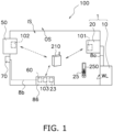
- FIG. 1 is a diagram schematically illustrating the air conditioning ventilation system 100 according to the embodiment.
- the air conditioning ventilation system 100 is a system that performs a compensation operation prior to a ventilation operation to moderate a temperature change in an indoor space IS (which corresponds to "indoor” described in the claims).
- the air conditioning ventilation system 100 mainly includes an air conditioner 1, a ventilator 50, an indoor environment sensor 60, and an outdoor sensor 70 (see FIG. 1 ).
- the air conditioner 1 is a device capable of performing the compensation operation.
- the ventilator 50 is a device capable of performing the ventilation operation.
- the indoor environment sensor 60 is a sensor unit capable of detecting environment of the indoor space IS. In the embodiment, the indoor environment sensor 60 is incorporated in a controller 86.
- the outdoor sensor 70 is a sensor unit capable of detecting an outdoor temperature.
- the air conditioner 1 includes a first wireless LAN adapter 101
- the ventilator 50 includes a second wireless LAN adapter 102
- the controller 86 includes a third wireless LAN adapter 103.
- an air conditioning control unit 9, a ventilation control unit 77, and a control unit 5 described later can perform wireless communication via a wireless LAN router 210.
- the air conditioning control unit 9, the ventilation control unit 77, and the control unit 5 can mutually transmit and receive control signals, information, and the like by performing wireless communication.
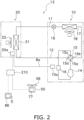
- FIG. 2 is a diagram schematically illustrating an overall configuration of the air conditioning ventilation system 100.
- the air conditioner 1 performs air conditioning of the indoor space IS by performing a cooling operation, a heating operation, or a dehumidifying operation.
- the air conditioner 1 according to the embodiment is a device capable of performing the compensation operation.
- a state in which the air conditioner 1 is performing the compensation operation may be referred to as a compensation operating mode.
- a state in which the air conditioner 1 is performing an operation other than the compensation operation may be referred to as a normal operating mode.
- the air conditioner 1 mainly includes an outdoor unit 10 installed in an outdoor space OS (which corresponds to "outdoor” in the claims), and an indoor unit 20 attached to a wall WL or the like of the indoor space IS.
- the outdoor unit 10 and the indoor unit 20 are connected by refrigerant connection pipes 11 and 12.
- the outdoor unit 10 and the indoor unit 20 are connected by the refrigerant connection pipes 11 and 12 to constitute a refrigerant circuit 13 (see FIG. 2 ).
- the air conditioner 1 performs a vapor compression refrigeration cycle in which a refrigerant sealed in the refrigerant circuit 13 is compressed, condensed, decompressed, evaporated, and then compressed again.
- the operation of the air conditioner 1 is controlled by the air conditioning control unit 9.
- the air conditioning control unit 9 is configured by connecting an outdoor-side control unit 10a and an indoor-side control unit 20a via a transmission line 8a, for example.
- the outdoor unit 10 is a device installed in the outdoor space OS.
- the outdoor unit 10 mainly includes a compressor 14, a four-way switching valve 15, an accumulator 16, an outdoor heat exchanger 17, an outdoor fan 18, an electric expansion valve 19, and the outdoor-side control unit 10a.
- the compressor 14 sucks the refrigerant from a suction pipe through a suction port, and compresses the sucked refrigerant.
- the compressed refrigerant is discharged from the compressor 14 through a discharge port.
- the refrigerant discharged from the compressor 14 is sent to a first port 15a of the four-way switching valve 15 through a discharge pipe.
- the four-way switching valve 15 is a mechanism that switches a flow direction of the refrigerant.
- the four-way switching valve 15 causes the refrigerant to flow between the first port 15a and a second port 15b and simultaneously causes the refrigerant to flow between a third port 15c and a fourth port 15d (see a solid line in FIG. 2 ).
- the four-way switching valve 15 causes the refrigerant to flow between the first port 15a and the fourth port 15d and simultaneously causes the refrigerant to flow between the second port 15b and the third port 15c (see a broken line in FIG. 2 ).
- the accumulator 16 is provided in the suction pipe connecting the third port 15c of the four-way switching valve 15 and the suction port of the compressor 14.
- the refrigerant flowing from the third port 15c of the four-way switching valve 15 to the compressor 14 is separated into a gas refrigerant and a liquid refrigerant.
- the gas refrigerant is mainly supplied from the accumulator 16 to the suction port of the compressor 14.
- the outdoor heat exchanger 17 exchanges heat between outdoor air and refrigerant.
- the outdoor heat exchanger 17 functions as a condenser for the refrigerant during the cooling operation.
- the outdoor heat exchanger 17 functions as a condenser for the refrigerant during the heating operation.
- the outdoor heat exchanger 17 according to the embodiment is, for example, a fin-and-tube heat exchanger having a plurality of heat transfer tubes and a plurality of heat transfer fins.
- the outdoor fan 18 is a fan that generates a flow of outdoor air flowing into the outdoor unit 10, passing through the outdoor heat exchanger 17, and flowing out to the outside of the outdoor unit 10.
- the outdoor fan 18 according to the embodiment is, for example, a propeller fan.
- the outdoor fan 18 is not limited to a propeller fan and may be appropriately selected.
- the electric expansion valve 19 is a valve for adjusting a refrigerant pressure between the outdoor heat exchanger 17 and the indoor heat exchanger 21, adjusting a refrigerant flow rate, and the like.
- the electric expansion valve 19 is adopted as an expansion mechanism, but the expansion mechanism is not limited to the electric expansion valve as long as being a mechanism capable of adjusting the refrigerant pressure, adjusting the refrigerant flow rate, and the like.
- the outdoor-side control unit 10a controls an operation of each component constituting the outdoor unit 10.
- the outdoor-side control unit 10a is implemented by a microcomputer, a memory, or the like.
- the microcomputer includes a control calculator and a storage.
- the control calculator may include a processor such as a central processing unit (CPU) or a graphics processing unit (GPU).
- the control calculator reads a program stored in the storage and performs predetermined calculation processing in accordance with the program.
- the control calculator can write a calculation result to the storage and read information stored in the storage in accordance with the program.
- the outdoor-side control unit 10a is electrically connected to the compressor 14, the four-way switching valve 15, the outdoor fan 18, the electric expansion valve 19, and the like included in the outdoor unit 10 so as to be able to transmit and receive control signals, information, and the like.
- the outdoor-side control unit 10a is connected to the indoor-side control unit 20a via the transmission line 8a so as to be able to transmit and receive control signals, information, and the like.
- the outdoor-side control unit 10a and the indoor-side control unit 20a are connected to constitute the air conditioning control unit 9 that controls the operation of the air conditioner 1.
- the indoor unit 20 is a wall-mounted indoor unit.
- the indoor unit 20 is not limited to this type, and the indoor unit 20 may be, for example, an indoor unit installed on a ceiling or a floor.
- the indoor unit 20 mainly includes the indoor heat exchanger 21, an indoor fan 22, and the indoor-side control unit 20a.
- the indoor heat exchanger 21 exchanges heat between indoor air and refrigerant.
- the indoor heat exchanger 21 functions as a refrigerant evaporator and cools indoor air during the cooling operation.
- the indoor heat exchanger 21 functions as a condenser for the refrigerant and heats the indoor air during the heating operation.
- the indoor heat exchanger 21 according to the embodiment is, for example, a fin-and-tube heat exchanger having a plurality of heat transfer tubes and a plurality of heat transfer fins.
- the indoor fan 22 is a fan that sucks indoor air into the indoor unit 20 and supplies air subjected to heat exchange with the refrigerant in the indoor heat exchanger 21 into the room.
- the indoor fan 22 according to the embodiment is a cross-flow fan that generates an air flow in a direction intersecting an axis by being rotationally driven.
- the indoor fan 22 is not limited to a cross-flow fan and may be appropriately selected.
- the indoor-side control unit 20a controls the operation of each component constituting the indoor unit 20.
- the indoor-side control unit 20a is implemented by a microcomputer, a memory, or the like.
- the microcomputer includes a control calculator and a storage.
- the control calculator may include a processor such as a CPU or a GPU.
- the control calculator reads a program stored in the storage and performs predetermined calculation processing in accordance with the program.
- the control calculator can write a calculation result to the storage and read information stored in the storage in accordance with the program.
- the indoor-side control unit 20a is electrically connected to the indoor fan 22 and the like so as to be able to transmit and receive control signals, information, and the like.
- the indoor-side control unit 20a is connected to the outdoor-side control unit 10a of the outdoor unit 10 via the transmission line 8a so as to be able to transmit and receive control signals, information, and the like.
- the indoor-side control unit 20a and the outdoor-side control unit 10a are connected to constitute the air conditioning control unit 9 that controls the operation of the air conditioner 1. Note that the indoor-side control unit 20a and the outdoor-side control unit 10a are not connected by the physical transmission line 8a, but may be connected to be communicable wirelessly.
- the indoor-side control unit 20a is configured to be able to receive various signals transmitted from a remote controller 25 for operating the indoor unit 20.
- the various signals include signals related to operation and stop of the indoor unit 20 and signals related to various settings.
- the signals related to the various settings include, for example, a switching signal of the operating modes and target temperatures of the cooling operation and the heating operation.
- the first wireless LAN adapter 101 is incorporated in the indoor unit 20 according to the embodiment (see FIG. 1 ).
- the indoor-side control unit 20a can communicate with the wireless LAN router 210 by using the first wireless LAN adapter 101.
- the ventilator 50 ventilates the indoor space IS by performing a ventilation operation described later. As illustrated in FIG. 1 , the ventilator 50 according to the embodiment is attached to the wall WL of the indoor space IS. However, the ventilator 50 may be installed on a ceiling, a floor surface, or the like of the indoor space IS.
- the ventilator 50 mainly includes a ventilation fan 56 that generates an air flow for supplying air, a ventilation fan motor (not shown) that drives the ventilation fan 56, and a ventilation control unit 77 that controls start, stop, and a number of rotations (air volume) of the ventilation fan motor.
- a ventilation fan 56 that generates an air flow for supplying air
- a ventilation fan motor (not shown) that drives the ventilation fan 56
- a ventilation control unit 77 that controls start, stop, and a number of rotations (air volume) of the ventilation fan motor.
- the configuration of the ventilator 50 is not limited to the above configuration, and the ventilator 50 may include, for example, a total heat exchanger or an active species generator.
- the ventilation control unit 77 includes a microcomputer, a memory, and the like for controlling the operation of each component constituting the ventilator 50.
- the second wireless LAN adapter 102 is incorporated in the ventilator 50 according to the embodiment (see FIG. 1 ).
- the ventilation control unit 77 can communicate with the wireless LAN router 210 by using the second wireless LAN adapter 102.
- the controller 86 is a device installed in the indoor space IS.
- the controller 86 mainly includes the indoor environment sensor 60, a notifier 23, and the control unit 5.
- the indoor environment sensor 60 is a sensor unit capable of detecting environment of the indoor space IS.
- the indoor environment sensor 60 according to the embodiment is a CO2 sensor capable of detecting a CO2 concentration in the indoor space IS.
- the CO2 concentration detected by the indoor environment sensor is transmitted to the control unit 5.
- the control unit 5 is implemented by a microcomputer, a memory, or the like.
- the control unit 5 includes a control calculator and a storage.
- the control calculator of the control unit 5 may include a processor such as a CPU or a GPU.
- the control calculator of the control unit 5 reads a program stored in the storage and performs predetermined calculation processing in accordance with the program.
- the control calculator can write a calculation result to the storage and read information stored in the storage in accordance with the program.
- the storage can be used as database.
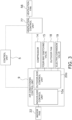
- the control unit 5 transmits and receives control signals, information, and the like to and from the air conditioning control unit 9 and the ventilation control unit 77 to control the operation of the air conditioner 1 and the ventilator 50.
- the notifier 23 is a device that notifies the user of a start and an end of the compensation operation.
- the notifier 23 according to the embodiment is, for example, a speaker incorporated in the controller 86.
- the example of the notifier 23 is not limited the speaker, and for example, the remote controller 25 including a display 250 may have a function as the notifier.
- the third wireless LAN adapter 103 is incorporated in the controller 86 according to the embodiment (see FIG. 1 ).
- the control unit 5 can communicate with the wireless LAN router 210 by using the third wireless LAN adapter 103.
- the outdoor sensor 70 is a sensor unit disposed in the outdoor space OS.
- the outdoor sensor 70 is a sensor unit capable of detecting a temperature of the outdoor space OS.
- the outdoor sensor 70 is connected to the controller 86 via a transmission line 8b so as to be able to transmit and receive various signals and information.
- the temperature of the outdoor space OS detected by the outdoor sensor 70 is transmitted to the control unit 5 of the controller 86 via the transmission line 8b.
- the ventilation operation is an operation implemented by the ventilator 50 supplying the air of the outdoor space OS to the indoor space IS.
- the ventilation operation is performed, the CO2 concentration in the indoor space IS decreases.
- a start timing of the ventilation operation is determined by the control unit 5.
- the control unit 5 determines the start timing of the ventilation operation on the basis of a detection value of the indoor environment sensor 60. For example, the control unit 5 starts the ventilation operation when the detection value detected by the indoor environment sensor 60 as a CO2 sensor exceeds a first threshold value.
- the first threshold value is a numerical value related to the CO2 concentration, and is herein, for example, 1000 ppm. Therefore, the control unit 5 according to the embodiment starts the ventilation operation when the CO2 concentration in the room exceeds 1000 ppm.
- the control unit 5 that has determined the start timing of the ventilation operation sends a control signal to the ventilation control unit 77 so as to start the ventilation operation at the start timing.
- the ventilation operation according to the embodiment is continued until the CO2 concentration in the room decreases to a predetermined concentration.
- the ventilation operation is continued until the CO2 concentration in the room becomes less than 800 ppm.
- the air (outside air) in the outdoor space OS is supplied to the indoor space IS.
- the outside air supplied to the indoor space IS may be air having a higher temperature or a lower temperature than the indoor air.
- the air conditioner 1 when the air conditioner 1 is performing the cooling operation (in a cooling season), there is a possibility that high-temperature outside air may be supplied to the indoor space IS along with the ventilation operation.
- the air conditioner 1 when the air conditioner 1 is performing the heating operation (in a heating season), there is a possibility that low-temperature outside air may be supplied to the indoor space IS along with the ventilation operation.
- high-temperature or low-temperature outside air is supplied to the indoor space IS, there is a possibility that the change may impair comfort of the user.
- the compensation operation is an operation performed prior to the ventilation operation.
- the compensation operation is an operation for compensating for a change in indoor temperature due to the ventilation operation. By performing the compensation operation, a temperature change of the indoor air accompanying the ventilation operation becomes moderate.
- a content of the compensation operation is determined by the control unit 5.
- the control unit 5 determines the content of the compensation operation on the basis of a detection value of the outdoor sensor 70.
- the control unit 5 determines a second target temperature on the basis of the detection value of the outdoor sensor 70.
- the second target temperature is a target temperature different from a first target temperature set at the start (immediately before the start) of the compensation operation by a predetermined temperature.
- the compensation operation is performed on the basis of the second target temperature.
- the first target temperature is substantially the same as a target temperature set in the normal operating mode. Therefore, it can be interpreted that the compensation operation is an operation performed prior to the ventilation operation and is an operation performed on the basis of a target temperature different by a predetermined temperature from the target temperature set in the normal operating mode.
- the outdoor temperature detected by the outdoor sensor 70 is 35°C
- the target temperature set in the air conditioner 1 at the start of the compensation operation is 27°C (the first target temperature is 27°C).
- the control unit 5 performs the compensation operation by performing the cooling operation based on the target temperature (for example, 24°C) lower than the first target temperature by a predetermined temperature.
- the outdoor temperature detected by the outdoor sensor 70 is 5°C
- the target temperature set in the air conditioner 1 at the start of the compensation operation is 20°C.
- the control unit 5 performs the compensation operation by performing the heating operation based on the target temperature (for example, 23°C) higher than the first target temperature by a predetermined temperature.
- the target temperature for example, 23°C
- a start timing of the compensation operation is determined by the control unit 5.
- the control unit 5 determines the start timing of the ventilation operation on the basis of the detection value of the indoor environment sensor 60. Specifically, the control unit 5 determines the start timing of the compensation operation on the basis of the CO2 concentration detected by the indoor environment sensor 60 as a CO2 sensor and a change rate of the CO2 concentration. For example, when it is predicted that the CO2 concentration in the indoor space IS exceeds the first threshold value after ten minutes, the control unit 5 determines to execute the compensation operation after five minutes, for example. Note that these numerical values are examples and can be changed as appropriate.
- the control unit 5 predicts after how many minutes the CO2 concentration in the room exceeds the first threshold value (after how many minutes the ventilation operation is started) on the basis of the change rate of the CO2 concentration.
- the second threshold value is a numerical value related to the CO2 concentration, and is herein, for example, 950 ppm.
- the change rate of the CO2 concentration can be calculated by confirming a transition of the CO2 concentration in the indoor space IS.
- the storage of the control unit 5 according to the embodiment stores in advance a program by which the control unit 5 confirms the detection value (CO2 concentration) of the indoor environment sensor 60 every five minutes.
- the CO2 concentration referred to by the control unit 5 is stored in the storage of the control unit 5 in chronological order.
- the storage of the control unit 5 stores the CO2 concentration 5 minutes before, the CO2 concentration 10 minutes before, and the CO2 concentration 15 minutes before, ....
- the control unit 5 can calculate the change rate of the CO2 concentration by performing predetermined calculation on the basis of the above data.
- the control unit 5 that has determined the start timing of the compensation operation sends a control signal to the air conditioning control unit 9 so as to start the compensation operation at the start timing.
- the compensation operation according to the embodiment ends on the basis of the start of the ventilation operation.
- the compensation operation ends simultaneously with the start of the ventilation operation.
- the control unit 5 may resume the normal operating mode after the end of the compensation operating mode.
- the air conditioning ventilation system 100 that has received an operation command from the user is controlled by the control unit 5 to operate in a flow as illustrated in a flowchart of FIG. 4 .
- the operation of the air conditioning ventilation system 100 will be described with reference to the flowchart illustrated in FIG. 4 .
- the flow of the flowchart illustrated in FIG. 4 is merely an example, and may be appropriately changed within a range without contradiction.
- other steps not illustrated may be included before and after each step, and the order of the steps may be appropriately changed within a range not contradictory to each other.
- step S1 the air conditioning ventilation system 100 starts the operation of the air conditioner 1. Specifically, the normal operating mode is started.
- step S2 the air conditioning ventilation system 100 confirms the detection value of the indoor environment sensor 60. Specifically, the air conditioning ventilation system 100 confirms the CO2 concentration in the indoor space IS.
- step S3 the air conditioning ventilation system 100 determines whether the CO2 concentration in the indoor space IS is greater than or equal to the second threshold value. When the CO2 concentration in the indoor space IS is greater than or equal to the second threshold value, the air conditioning ventilation system 100 proceeds to step S4. When the CO2 concentration in the indoor space IS is less than the second threshold value, the air conditioning ventilation system 100 returns to step S2.
- step S4 the air conditioning ventilation system 100 determines the start timing of the compensation operation on the basis of the change rate of the CO2 concentration in the indoor space IS.
- step S5 the air conditioning ventilation system 100 confirms the detection value of the outdoor sensor 70. Specifically, the air conditioning ventilation system 100 confirms the temperature of the outdoor air.
- step S6 the air conditioning ventilation system 100 determines the content of the compensation operation on the basis of the detection value of the outdoor sensor 70.
- step S7 the air conditioning ventilation system 100 compares the start timing determined in step S4 with a current time.
- the air conditioning ventilation system 100 starts the compensation operation when the current time coincides with the start timing determined in step S4.
- the notifier 23 notifies the user of the start of the compensation operation.
- step S8 the air conditioning ventilation system 100 determines whether the CO2 concentration in the indoor space IS is greater than or equal to the first threshold value on the basis of the detection value of the indoor environment sensor 60. When the CO2 concentration in the indoor space IS is greater than or equal to the first threshold value, the air conditioning ventilation system 100 proceeds to step S9. When the CO2 concentration in the indoor space IS is less than the first threshold value, the air conditioning ventilation system 100 continues the compensation operation until the CO2 concentration in the indoor space IS becomes greater than or equal to the first threshold value.
- step S9 the air conditioning ventilation system 100 ends the compensation operation and starts the ventilation operation.
- step S9 the notifier 23 notifies the user of the end of the compensation operation.
- step S10 the air conditioning ventilation system 100 confirms whether the CO2 concentration in the room is less than a predetermined value.
- the air conditioning ventilation system 100 proceeds to step S11.
- the air conditioning ventilation system 100 continues the ventilation operation until the CO2 concentration in the room becomes less than the predetermined value.
- step S11 the air conditioning ventilation system 100 ends the ventilation operation.
- the air conditioning ventilation system 100 that has performed the operation in step S11 may repeat the operations in steps S2 to S11 until receiving an operation end command from the user.
- Patent Literature 1 that controls an air conditioning capacity according to a temperature of supplied outdoor air when the outdoor air is supplied to the air conditioning target space.
- the air conditioning capacity is controlled when the outdoor air is supplied. Therefore, the temperature of the air conditioning target space temporarily changes, and there is a possibility that the change may impair comfort of the user. In particular, immediately after the supply of outdoor air is started, there is a possibility that the temperature of the air conditioning target space may change significantly.
- the air conditioning ventilation system 100 includes the air conditioner 1, the ventilator 50, and the control unit 5.
- the control unit 5 controls the operations of the air conditioner 1 and the ventilator 50.
- the control unit 5 causes the air conditioner 1 to perform the compensation operation prior to the ventilation operation to be performed by the ventilator 50.
- the compensation operation is an operation for compensating for a change in indoor temperature due to the ventilation operation.
- the control unit 5 of the air conditioning ventilation system 100 performs the compensation operation for compensating for a change in the indoor temperature due to the ventilation operation.
- the compensation operation is performed prior to the ventilation operation.
- This configuration can adjust the temperature of the indoor air in advance in accordance with the temperature of the air introduced along with the ventilation operation. Thus, even when the outdoor air is supplied to the indoor space IS along with the ventilation operation, the temperature change of the indoor air becomes moderate. Therefore, comfort of a user is maintained.
- the air conditioning ventilation system 100 further includes the indoor environment sensor 60 that detects an indoor environment.
- the control unit 5 determines the start timing of the ventilation operation on the basis of the detection value of the indoor environment sensor 60.
- This configuration allows the control unit 5 to start the ventilation operation at an appropriate timing. It is therefore possible to minimize a frequency at which the temperature change of the indoor air occurs. Accordingly, the temperature of the indoor air is stabilized.
- the stabilization of the temperature of the indoor air maintains the comfort of the user.
- the air conditioning ventilation system 100 further includes the indoor environment sensor 60 that detects the indoor environment.
- the control unit 5 determines the start timing of the compensation operation on the basis of the detection value of the indoor environment sensor 60.
- This configuration allows the control unit 5 to start the compensation operation at an appropriate timing.
- the air conditioning ventilation system 100 further includes the outdoor sensor 70 that detects the outdoor temperature.
- the control unit 5 determines the content of the compensation operation on the basis of a detection value of the outdoor sensor 70.
- This configuration allows the control unit 5 to determine the content of the compensation operation on the basis of the outdoor temperature.
- control unit 5 determines the start timing of the compensation operation on the basis of the detection value of the indoor environment sensor 60 and the change rate of the detection value of the indoor environment sensor 60.
- control unit 5 can start the compensation operation at an appropriate timing. Specifically, the control unit 5 can start the compensation operation at a timing at which the operation time of the compensation operation does not become excessively long. In addition, the control unit 5 can start the compensation operation at a timing at which the operation time of the compensation operation does not become insufficient.
- the compensation operation is a cooling operation or a heating operation based on the second target temperature different by a predetermined temperature from the first target temperature set at the start of the compensation operation.
- This configuration allows the compensation operation to be performed at a target temperature higher or lower than the target temperature set at the start of the compensation operation.
- control unit 5 ends the compensation operation on the basis of the start of the ventilation operation.
- the air conditioning ventilation system 100 further includes the notifier 23 that notifies the user of the start and the end of the compensation operation.
- control unit 5 causes the air conditioner 1 to perform the compensation operation to moderate the change in the temperature of the indoor air due to the ventilation operation.
- example of the compensation operation is not limited to this example.
- the following operation may be performed.
- control unit 5 may cause the air conditioner 1 to perform the compensation operation to moderate the change in the humidity of the indoor air due to the ventilation operation.
- the dehumidifying operation may be performed.
- the outdoor sensor 70 may be a sensor that detects outdoor humidity.
- the air conditioning ventilation system can moderate the change in the humidity of the indoor air. Therefore, comfort of a user is maintained.
- control unit 5 may cause the air conditioner 1 to perform the compensation operation to moderate the change in the indoor temperature and humidity due to the ventilation operation.
- the cooling operation or the heating operation and the dehumidifying operation may be performed.
- the cooling operation may be performed for a predetermined time after the dehumidifying operation is performed for a predetermined time.
- the outdoor sensor 70 may be a sensor that detects outdoor temperature and humidity.
- the air conditioning ventilation system can moderate the changes in the temperature and humidity of the indoor air. Therefore, comfort of a user is maintained.
- control unit 5 determines the start timing of the compensation operation on the basis of the detection value of the indoor environment sensor 60 and the change rate of the detection value of the indoor environment sensor 60.
- control unit 5 may start the compensation operation when the detection value of the indoor environment sensor 60 exceeds the second threshold value, and may start the ventilation operation when the detection value of the indoor environment sensor 60 exceeds the first threshold value higher than the second threshold value.
- the control unit 5 starts the compensation operation when the CO2 concentration exceeds 950 ppm, and starts the ventilation operation when the CO2 concentration exceeds 1000 ppm.
- control unit 5 ends the compensation operation simultaneously with the start of the ventilation operation.
- the example of the control by the control unit 5 is not limited to the above example, and the control unit 5 may end the compensation operation after a predetermined time has elapsed from the start of the ventilation operation.
- the control unit 5 may confirm whether the predetermined time has elapsed from the start of the ventilation operation by measuring with a timer (not shown) or the like.
- control unit 5 may end the compensation operation on the basis of the elapsed time from the start of the compensation operation. Specifically, the compensation operation may be terminated after a predetermined time has elapsed from the start of the compensation operation. In this case, the control unit 5 may confirm whether the predetermined time has elapsed from the start of the compensation operation by measuring with a timer (not shown) or the like.
- control unit 5 may end the compensation operation on the basis of the detection value of the indoor environment sensor 60.
- control unit 5 may end the compensation operation when the detection value of the indoor environment sensor 60 does not increase after a predetermined time has elapsed from the start of the compensation operation.
- the paired air conditioner 1 in which one outdoor unit and one indoor unit are connected in parallel by the refrigerant connection pipes 11 and 12 has been described.
- the configuration of the air conditioner is not limited to the above configuration.
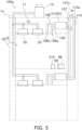
- the air conditioner may be a multi-type air conditioner 1a in which a plurality of indoor units 20 is connected to one outdoor unit 10 (see FIG. 5 ).
- the ventilator 50 communicating with the outdoor space OS has been described.
- the configuration of the ventilator is not limited to the above configuration.
- the ventilator 50 may include a device body 51 connected to an intake duct 107 connected to an intake port 107a for taking the outdoor air into the indoor space IS, an air supply duct 108 connected to an air supply port 108a for supplying the outdoor air to the indoor space IS, an extraction duct 109 connected to an extraction port 109a for extracting the indoor air from the indoor space IS, and an exhaust duct 110 connected to a discharge port 110a for discharging the indoor air to the outdoor space OS (see FIG. 5 ).
- the air conditioning ventilation system 100 includes the indoor environment sensor 60
- the control unit 5 of the air conditioning ventilation system 100 determines the start timing of the compensation operation on the basis of the detection value of the indoor environment sensor 60 and the change rate of the detection value of the indoor environment sensor 60.
- the control unit 5 starts the ventilation operation when the CO2 concentration detected by the indoor environment sensor 60 exceeds the first threshold value.
- the configuration of the air conditioning ventilation system 100 is not limited to the above configuration, and the air conditioning ventilation system is not required to include the indoor environment sensor 60, for example.
- the start timing of the compensation operation and the ventilation operation may be stored in advance in the storage of the control unit 5.
- the storage of the control unit 5 may store a program that causes the ventilator 50 to perform the ventilation operation every time a predetermined time elapses. Specifically, the storage of the control unit 5 may store a program that causes the ventilation operation to be performed once per hour. The storage of the control unit 5 may store a program that causes the compensation operation to be performed ten minutes before the ventilation operation.
- control unit 5 may store in advance an execution time (for example, ten minutes) of the ventilation operation and an execution time (for example, five minutes) of the compensation operation.
- the air conditioning ventilation system according to this modification does not include the indoor environment sensor 60. Therefore, a manufacturing cost of the air conditioning ventilation system is reduced.
- the air conditioning ventilation system 100 includes the indoor environment sensor 60, and the control unit 5 of the air conditioning ventilation system 100 determines the start timing of the compensation operation on the basis of the detection value of the indoor environment sensor 60 and the change rate of the detection value of the indoor environment sensor 60.
- the configuration of the air conditioning ventilation system 100 is not limited to the above configuration.
- the air conditioning ventilation system may include, for example, a human sensor capable of detecting the number of users present in the indoor space IS, instead of the indoor environment sensor 60.
- control unit 5 may schematically calculate the CO2 concentration in the indoor space IS on the basis of the number of users present in the indoor space IS, a staying time length of each user present in the indoor space IS, a floor area of the indoor space IS, and the like.
- the start timing of the compensation operation and the ventilation operation may be determined on the basis of the CO2 concentration in the indoor space IS calculated by the control unit 5.
- the air conditioning ventilation system may further include a human sensor in addition to the indoor environment sensor 60.
- the control unit 5 may consider the number of users present in the indoor space IS when calculating the change rate of the detection value of the indoor environment sensor 60. This configuration can correct the change rate of the detection value of the indoor environment sensor 60 in accordance with an increase or decrease of the user present in the indoor space IS. It is therefore possible to start the compensation operation at an appropriate timing.
- the ventilator 50 is installed in the indoor space IS and the ventilator 50 performs the ventilation operation.
- the configuration of the air conditioning ventilation system 100 is not limited to the above configuration.
- the ventilator 50 may be integrated with the air conditioner.
- the air conditioner according to this modification may include an outdoor unit including the ventilator 50 and an suction and exhaust hose, for example.
- the suction and exhaust hose is a hose that allows the indoor space IS and the outdoor unit to communicate with each other, and serves as a passage for an air flow generated by the ventilator 50.
- the air conditioner can supply the outdoor air to the indoor space IS through the suction and exhaust hose by driving the ventilator 50 included in the outdoor unit.
- the configuration of the air conditioning ventilation system 100 is not limited to the above configuration.
- the air conditioner 1 or the ventilator 50 may include the control unit 5.
- the control unit 5 is not required to have some or all of the functions described in the above embodiment.
- some or all of the functions of the control unit 5 described in the above embodiment may be implemented by a server or the like installed in a place different from the air conditioning ventilation system.
- the functions of the control unit 5 is not required to be executed only by the air conditioning ventilation system, and may be implemented by a server (not shown) or the like installed separately from the air conditioning ventilation system.
- the air conditioning control unit 9, the ventilation control unit 77, and the control unit 5 mutually transmit and receive control signals, information, and the like by performing wireless communication via the wireless LAN router 210.
- the air conditioning ventilation system is not limited to this example.
- the air conditioning control unit 9, the ventilation control unit 77, and the control unit 5 may be connected by physical wires (communication lines).
- the air conditioning control unit 9, the ventilation control unit 77, and the control unit 5 may mutually transmit and receive control signals, information, and the like via physical wires.
- the present disclosure is not limited to the embodiments without any change.
- the present disclosure can be embodied, upon implementation, with any modification to any constituent element within a range not departing from the gist.
- the present disclosure can be presented in various manners with appropriate combinations of a plurality of constituent elements disclosed in the respective embodiments. For example, some may be excluded from all the constituent elements according to the embodiments.
- constituent elements according to different embodiment may be combined with each other as appropriate. Therefore, it should be considered that the present embodiments are merely examples in all respects and are not limiting, and it is intended that any modification obvious to a person skilled in the art is included in the embodiments.
- Patent Literature 1 JP H08-145432 A
Landscapes
- Engineering & Computer Science (AREA)
- Chemical & Material Sciences (AREA)
- General Engineering & Computer Science (AREA)
- Mechanical Engineering (AREA)
- Combustion & Propulsion (AREA)
- Signal Processing (AREA)
- Physics & Mathematics (AREA)
- Mathematical Physics (AREA)
- Fuzzy Systems (AREA)
- Automation & Control Theory (AREA)
- General Physics & Mathematics (AREA)
- Fluid Mechanics (AREA)
- Human Computer Interaction (AREA)
- Air Conditioning Control Device (AREA)
- Ventilation (AREA)
Abstract
Description
- The present disclosure relates to an air conditioning ventilation system.
- When a ventilation operation is performed by using a ventilator, there is a possibility that outside air supplied to an air conditioning target space along with ventilation may change temperature and humidity of air in the air conditioning target space.
- To solve such a problem, there is conventionally known an air conditioner as disclosed in Patent Literature 1 (
JP H08-145432 A - In the air conditioner disclosed in
Patent Literature 1, the air conditioning capacity is controlled when outdoor air is supplied. Therefore, the temperature and humidity of the air in the air conditioning target space temporarily change, and there is a possibility that the change may impair comfort of a user. - An air conditioning ventilation system according to a first aspect includes an air conditioner, a ventilator, and a control unit. The control unit controls operations of the air conditioner and the ventilator. The control unit causes the air conditioner to perform a compensation operation prior to a ventilation operation to be performed by the ventilator. The compensation operation is an operation for compensating for a change in indoor temperature and/or humidity due to the ventilation operation.
- The control unit of the air conditioning ventilation system according to the first aspect performs the compensation operation for compensating for a change in the indoor temperature and/or humidity due to the ventilation operation. The compensation operation is performed prior to the ventilation operation. This configuration can adjust a temperature and/or humidity of indoor air in advance in accordance with a temperature and/or humidity of air introduced along with the ventilation operation. Thus, even when the outdoor air is supplied to a room along with the ventilation operation, a change in the temperature and/or humidity of the indoor air becomes moderate. Therefore, comfort of a user is maintained.
- An air conditioning ventilation system according to a second aspect is the system according to the first aspect and further includes an indoor environment sensor that detects an indoor environment. The control unit determines a start timing of the ventilation operation on the basis of a detection value of the indoor environment sensor.
- This configuration allows the control unit to start the ventilation operation at an appropriate timing.
- An air conditioning ventilation system according to a third aspect is the system according to the first or second aspect and further includes an indoor environment sensor that detects an indoor environment. The control unit determines a start timing of the compensation operation on the basis of a detection value of the indoor environment sensor.
- This configuration allows the control unit to start the compensation operation at an appropriate timing.
- An air conditioning ventilation system according to a fourth aspect is the system according to any one of the first to third aspects and further includes an outdoor sensor that detects outdoor temperature and/or humidity. The control unit determines a content of the compensation operation on the basis of a detection value of the outdoor sensor.
- This configuration allows the control unit to determine the content of the compensation operation on the basis of the outdoor temperature.
- An air conditioning ventilation system according to a fifth aspect is the system according to the second or third aspect, in which the control unit determines the start timing of the compensation operation on the basis of the detection value of the indoor environment sensor and a change rate of the detection value of the indoor environment sensor.
- This configuration allows the control unit to start the compensation operation at an appropriate timing.
- An air conditioning ventilation system according to a sixth aspect is the system according to the second or third aspect, in which the control unit starts the compensation operation when the detection value of the indoor environment sensor exceeds a second threshold value. The control unit starts the ventilation operation when the detection value of the indoor environment sensor exceeds a first threshold value higher than the second threshold value.
- An air conditioning ventilation system according to a seventh aspect is the system according to any one of the first to sixth aspects, in which the compensation operation is a cooling operation, a dehumidifying operation, or a heating operation based on a second target temperature different by a predetermined temperature from a first target temperature set at a start of the compensation operation.
- An air conditioning ventilation system according to an eighth aspect is the system according to the fifth or sixth aspect, in which the control unit ends the compensation operation on the basis of a start of the ventilation operation. Alternatively, the control unit ends the compensation operation on the basis of an elapsed time from the start of the compensation operation. Alternatively, the control unit ends the compensation operation on the basis of the detection value of the indoor environment sensor.
- An air conditioning ventilation system according to a ninth aspect is the system according to any one of the first to eighth aspects and further includes a notifier that notifies a user of a start and/or end of the compensation operation.
-
-
FIG. 1 is a schematic diagram of an air conditioning ventilation system. -
FIG. 2 is a diagram schematically illustrating an overall configuration of the air conditioning ventilation system. -
FIG. 3 is a control block diagram of the air conditioning ventilation system. -
FIG. 4 is a flowchart illustrating a flow of processing performed by a control unit during a compensation operation and a ventilation operation. -
FIG. 5 is a schematic diagram of the air conditioning ventilation system. - Hereinafter, an embodiment of an air conditioning ventilation system of the present disclosure will be described with reference to the drawings as appropriate. However, unnecessarily detailed description may be omitted. For example, a detailed description of already well-known matters and duplicate description of substantially the same configuration may be omitted. This is to avoid unnecessary redundancy of the following description and to facilitate understanding of those skilled in the art.
- Each drawing is not necessarily strictly illustrated. In each drawing, substantially the same components are denoted by the same reference signs, and duplicate description is omitted or simplified.
- First, an air
conditioning ventilation system 100 will be described with reference toFIG. 1. FIG. 1 is a diagram schematically illustrating the airconditioning ventilation system 100 according to the embodiment. The airconditioning ventilation system 100 is a system that performs a compensation operation prior to a ventilation operation to moderate a temperature change in an indoor space IS (which corresponds to "indoor" described in the claims). The airconditioning ventilation system 100 mainly includes anair conditioner 1, aventilator 50, anindoor environment sensor 60, and an outdoor sensor 70 (seeFIG. 1 ). Theair conditioner 1 is a device capable of performing the compensation operation. Theventilator 50 is a device capable of performing the ventilation operation. Theindoor environment sensor 60 is a sensor unit capable of detecting environment of the indoor space IS. In the embodiment, theindoor environment sensor 60 is incorporated in acontroller 86. Theoutdoor sensor 70 is a sensor unit capable of detecting an outdoor temperature. - In the embodiment, the
air conditioner 1 includes a firstwireless LAN adapter 101, theventilator 50 includes a secondwireless LAN adapter 102, and thecontroller 86 includes a thirdwireless LAN adapter 103. As a result, an airconditioning control unit 9, aventilation control unit 77, and acontrol unit 5 described later can perform wireless communication via awireless LAN router 210. The airconditioning control unit 9, theventilation control unit 77, and thecontrol unit 5 can mutually transmit and receive control signals, information, and the like by performing wireless communication. - The
air conditioner 1 will be described with reference toFIGS. 1 and2. FIG. 2 is a diagram schematically illustrating an overall configuration of the airconditioning ventilation system 100. Theair conditioner 1 performs air conditioning of the indoor space IS by performing a cooling operation, a heating operation, or a dehumidifying operation. Theair conditioner 1 according to the embodiment is a device capable of performing the compensation operation. Hereinafter, a state in which theair conditioner 1 is performing the compensation operation may be referred to as a compensation operating mode. Furthermore, a state in which theair conditioner 1 is performing an operation other than the compensation operation may be referred to as a normal operating mode. - As illustrated in
FIGS. 1 and2 , theair conditioner 1 mainly includes anoutdoor unit 10 installed in an outdoor space OS (which corresponds to "outdoor" in the claims), and anindoor unit 20 attached to a wall WL or the like of the indoor space IS. Theoutdoor unit 10 and theindoor unit 20 are connected byrefrigerant connection pipes air conditioner 1, theoutdoor unit 10 and theindoor unit 20 are connected by therefrigerant connection pipes FIG. 2 ). Theair conditioner 1 performs a vapor compression refrigeration cycle in which a refrigerant sealed in therefrigerant circuit 13 is compressed, condensed, decompressed, evaporated, and then compressed again. - The operation of the
air conditioner 1 is controlled by the airconditioning control unit 9. The airconditioning control unit 9 is configured by connecting an outdoor-side control unit 10a and an indoor-side control unit 20a via atransmission line 8a, for example. - The
outdoor unit 10 is a device installed in the outdoor space OS. Theoutdoor unit 10 mainly includes acompressor 14, a four-way switching valve 15, anaccumulator 16, anoutdoor heat exchanger 17, anoutdoor fan 18, anelectric expansion valve 19, and the outdoor-side control unit 10a. - The
compressor 14 sucks the refrigerant from a suction pipe through a suction port, and compresses the sucked refrigerant. The compressed refrigerant is discharged from thecompressor 14 through a discharge port. The refrigerant discharged from thecompressor 14 is sent to afirst port 15a of the four-way switching valve 15 through a discharge pipe. - The four-
way switching valve 15 is a mechanism that switches a flow direction of the refrigerant. When theair conditioner 1 performs the cooling operation, the four-way switching valve 15 causes the refrigerant to flow between thefirst port 15a and asecond port 15b and simultaneously causes the refrigerant to flow between athird port 15c and afourth port 15d (see a solid line inFIG. 2 ). When theair conditioner 1 performs the heating operation, the four-way switching valve 15 causes the refrigerant to flow between thefirst port 15a and thefourth port 15d and simultaneously causes the refrigerant to flow between thesecond port 15b and thethird port 15c (see a broken line inFIG. 2 ). - The
accumulator 16 is provided in the suction pipe connecting thethird port 15c of the four-way switching valve 15 and the suction port of thecompressor 14. In theaccumulator 16, the refrigerant flowing from thethird port 15c of the four-way switching valve 15 to thecompressor 14 is separated into a gas refrigerant and a liquid refrigerant. The gas refrigerant is mainly supplied from theaccumulator 16 to the suction port of thecompressor 14. - The
outdoor heat exchanger 17 exchanges heat between outdoor air and refrigerant. Theoutdoor heat exchanger 17 functions as a condenser for the refrigerant during the cooling operation. Theoutdoor heat exchanger 17 functions as a condenser for the refrigerant during the heating operation. Theoutdoor heat exchanger 17 according to the embodiment is, for example, a fin-and-tube heat exchanger having a plurality of heat transfer tubes and a plurality of heat transfer fins. - The
outdoor fan 18 is a fan that generates a flow of outdoor air flowing into theoutdoor unit 10, passing through theoutdoor heat exchanger 17, and flowing out to the outside of theoutdoor unit 10. Theoutdoor fan 18 according to the embodiment is, for example, a propeller fan. Theoutdoor fan 18 is not limited to a propeller fan and may be appropriately selected. - The
electric expansion valve 19 is a valve for adjusting a refrigerant pressure between theoutdoor heat exchanger 17 and theindoor heat exchanger 21, adjusting a refrigerant flow rate, and the like. In the embodiment, theelectric expansion valve 19 is adopted as an expansion mechanism, but the expansion mechanism is not limited to the electric expansion valve as long as being a mechanism capable of adjusting the refrigerant pressure, adjusting the refrigerant flow rate, and the like. - The outdoor-
side control unit 10a controls an operation of each component constituting theoutdoor unit 10. - The outdoor-
side control unit 10a is implemented by a microcomputer, a memory, or the like. The microcomputer includes a control calculator and a storage. The control calculator may include a processor such as a central processing unit (CPU) or a graphics processing unit (GPU). The control calculator reads a program stored in the storage and performs predetermined calculation processing in accordance with the program. The control calculator can write a calculation result to the storage and read information stored in the storage in accordance with the program. The outdoor-side control unit 10a is electrically connected to thecompressor 14, the four-way switching valve 15, theoutdoor fan 18, theelectric expansion valve 19, and the like included in theoutdoor unit 10 so as to be able to transmit and receive control signals, information, and the like. The outdoor-side control unit 10a is connected to the indoor-side control unit 20a via thetransmission line 8a so as to be able to transmit and receive control signals, information, and the like. The outdoor-side control unit 10a and the indoor-side control unit 20a are connected to constitute the airconditioning control unit 9 that controls the operation of theair conditioner 1. - As illustrated in
FIG. 1 , theindoor unit 20 according to the embodiment is a wall-mounted indoor unit. However, theindoor unit 20 is not limited to this type, and theindoor unit 20 may be, for example, an indoor unit installed on a ceiling or a floor. Theindoor unit 20 mainly includes theindoor heat exchanger 21, anindoor fan 22, and the indoor-side control unit 20a. - The
indoor heat exchanger 21 exchanges heat between indoor air and refrigerant. Theindoor heat exchanger 21 functions as a refrigerant evaporator and cools indoor air during the cooling operation. Theindoor heat exchanger 21 functions as a condenser for the refrigerant and heats the indoor air during the heating operation. Theindoor heat exchanger 21 according to the embodiment is, for example, a fin-and-tube heat exchanger having a plurality of heat transfer tubes and a plurality of heat transfer fins. - The
indoor fan 22 is a fan that sucks indoor air into theindoor unit 20 and supplies air subjected to heat exchange with the refrigerant in theindoor heat exchanger 21 into the room. Theindoor fan 22 according to the embodiment is a cross-flow fan that generates an air flow in a direction intersecting an axis by being rotationally driven. Theindoor fan 22 is not limited to a cross-flow fan and may be appropriately selected. - The indoor-
side control unit 20a controls the operation of each component constituting theindoor unit 20. - The indoor-
side control unit 20a is implemented by a microcomputer, a memory, or the like. The microcomputer includes a control calculator and a storage. The control calculator may include a processor such as a CPU or a GPU. The control calculator reads a program stored in the storage and performs predetermined calculation processing in accordance with the program. The control calculator can write a calculation result to the storage and read information stored in the storage in accordance with the program. The indoor-side control unit 20a is electrically connected to theindoor fan 22 and the like so as to be able to transmit and receive control signals, information, and the like. The indoor-side control unit 20a is connected to the outdoor-side control unit 10a of theoutdoor unit 10 via thetransmission line 8a so as to be able to transmit and receive control signals, information, and the like. The indoor-side control unit 20a and the outdoor-side control unit 10a are connected to constitute the airconditioning control unit 9 that controls the operation of theair conditioner 1. Note that the indoor-side control unit 20a and the outdoor-side control unit 10a are not connected by thephysical transmission line 8a, but may be connected to be communicable wirelessly. - The indoor-
side control unit 20a is configured to be able to receive various signals transmitted from aremote controller 25 for operating theindoor unit 20. The various signals include signals related to operation and stop of theindoor unit 20 and signals related to various settings. The signals related to the various settings include, for example, a switching signal of the operating modes and target temperatures of the cooling operation and the heating operation. - The first
wireless LAN adapter 101 is incorporated in theindoor unit 20 according to the embodiment (seeFIG. 1 ). The indoor-side control unit 20a can communicate with thewireless LAN router 210 by using the firstwireless LAN adapter 101. - The
ventilator 50 ventilates the indoor space IS by performing a ventilation operation described later. As illustrated inFIG. 1 , theventilator 50 according to the embodiment is attached to the wall WL of the indoor space IS. However, theventilator 50 may be installed on a ceiling, a floor surface, or the like of the indoor space IS. - The
ventilator 50 according to the embodiment mainly includes aventilation fan 56 that generates an air flow for supplying air, a ventilation fan motor (not shown) that drives theventilation fan 56, and aventilation control unit 77 that controls start, stop, and a number of rotations (air volume) of the ventilation fan motor. Note that the configuration of theventilator 50 is not limited to the above configuration, and theventilator 50 may include, for example, a total heat exchanger or an active species generator. - The
ventilation control unit 77 includes a microcomputer, a memory, and the like for controlling the operation of each component constituting theventilator 50. - The second
wireless LAN adapter 102 is incorporated in theventilator 50 according to the embodiment (seeFIG. 1 ). Theventilation control unit 77 can communicate with thewireless LAN router 210 by using the secondwireless LAN adapter 102. - The
controller 86 is a device installed in the indoor space IS. Thecontroller 86 mainly includes theindoor environment sensor 60, anotifier 23, and thecontrol unit 5. - The
indoor environment sensor 60 is a sensor unit capable of detecting environment of the indoor space IS. Theindoor environment sensor 60 according to the embodiment is a CO2 sensor capable of detecting a CO2 concentration in the indoor space IS. The CO2 concentration detected by the indoor environment sensor is transmitted to thecontrol unit 5. - The
control unit 5 is implemented by a microcomputer, a memory, or the like. Thecontrol unit 5 includes a control calculator and a storage. The control calculator of thecontrol unit 5 may include a processor such as a CPU or a GPU. The control calculator of thecontrol unit 5 reads a program stored in the storage and performs predetermined calculation processing in accordance with the program. The control calculator can write a calculation result to the storage and read information stored in the storage in accordance with the program. The storage can be used as database. Thecontrol unit 5 according to the embodiment transmits and receives control signals, information, and the like to and from the airconditioning control unit 9 and theventilation control unit 77 to control the operation of theair conditioner 1 and theventilator 50. - The
notifier 23 is a device that notifies the user of a start and an end of the compensation operation. Thenotifier 23 according to the embodiment is, for example, a speaker incorporated in thecontroller 86. However, the example of thenotifier 23 is not limited the speaker, and for example, theremote controller 25 including adisplay 250 may have a function as the notifier. - The third
wireless LAN adapter 103 is incorporated in thecontroller 86 according to the embodiment (seeFIG. 1 ). Thecontrol unit 5 can communicate with thewireless LAN router 210 by using the thirdwireless LAN adapter 103. - As illustrated in
FIG. 1 , theoutdoor sensor 70 is a sensor unit disposed in the outdoor space OS. Theoutdoor sensor 70 is a sensor unit capable of detecting a temperature of the outdoor space OS. Theoutdoor sensor 70 is connected to thecontroller 86 via atransmission line 8b so as to be able to transmit and receive various signals and information. The temperature of the outdoor space OS detected by theoutdoor sensor 70 is transmitted to thecontrol unit 5 of thecontroller 86 via thetransmission line 8b. - Hereinafter, the ventilation operation performed by the
ventilator 50 and the compensation operation performed by theair conditioner 1 will be described in detail. - The ventilation operation is an operation implemented by the
ventilator 50 supplying the air of the outdoor space OS to the indoor space IS. When the ventilation operation is performed, the CO2 concentration in the indoor space IS decreases. - In the embodiment, a start timing of the ventilation operation is determined by the
control unit 5. Thecontrol unit 5 determines the start timing of the ventilation operation on the basis of a detection value of theindoor environment sensor 60. For example, thecontrol unit 5 starts the ventilation operation when the detection value detected by theindoor environment sensor 60 as a CO2 sensor exceeds a first threshold value. The first threshold value is a numerical value related to the CO2 concentration, and is herein, for example, 1000 ppm. Therefore, thecontrol unit 5 according to the embodiment starts the ventilation operation when the CO2 concentration in the room exceeds 1000 ppm. Thecontrol unit 5 that has determined the start timing of the ventilation operation sends a control signal to theventilation control unit 77 so as to start the ventilation operation at the start timing. - The ventilation operation according to the embodiment is continued until the CO2 concentration in the room decreases to a predetermined concentration. For example, the ventilation operation is continued until the CO2 concentration in the room becomes less than 800 ppm.
- As described above, when the ventilation operation is performed, the air (outside air) in the outdoor space OS is supplied to the indoor space IS. At this time, there is a possibility that the outside air supplied to the indoor space IS may be air having a higher temperature or a lower temperature than the indoor air. For example, when the
air conditioner 1 is performing the cooling operation (in a cooling season), there is a possibility that high-temperature outside air may be supplied to the indoor space IS along with the ventilation operation. Alternatively, when theair conditioner 1 is performing the heating operation (in a heating season), there is a possibility that low-temperature outside air may be supplied to the indoor space IS along with the ventilation operation. When high-temperature or low-temperature outside air is supplied to the indoor space IS, there is a possibility that the change may impair comfort of the user. - The compensation operation is an operation performed prior to the ventilation operation. The compensation operation is an operation for compensating for a change in indoor temperature due to the ventilation operation. By performing the compensation operation, a temperature change of the indoor air accompanying the ventilation operation becomes moderate.
- In the embodiment, a content of the compensation operation is determined by the
control unit 5. Thecontrol unit 5 determines the content of the compensation operation on the basis of a detection value of theoutdoor sensor 70. For example, thecontrol unit 5 determines a second target temperature on the basis of the detection value of theoutdoor sensor 70. The second target temperature is a target temperature different from a first target temperature set at the start (immediately before the start) of the compensation operation by a predetermined temperature. The compensation operation is performed on the basis of the second target temperature. Note that the first target temperature is substantially the same as a target temperature set in the normal operating mode. Therefore, it can be interpreted that the compensation operation is an operation performed prior to the ventilation operation and is an operation performed on the basis of a target temperature different by a predetermined temperature from the target temperature set in the normal operating mode. - For example, it is assumed that the outdoor temperature detected by the
outdoor sensor 70 is 35°C, and the target temperature set in theair conditioner 1 at the start of the compensation operation is 27°C (the first target temperature is 27°C). As described above, in a case where there is a possibility that the temperature of the indoor air may rise due to the ventilation operation, thecontrol unit 5 performs the compensation operation by performing the cooling operation based on the target temperature (for example, 24°C) lower than the first target temperature by a predetermined temperature. Alternatively, it is assumed that the outdoor temperature detected by theoutdoor sensor 70 is 5°C, and the target temperature set in theair conditioner 1 at the start of the compensation operation is 20°C. As described above, in a case where there is a possibility that the temperature of the indoor air may decrease due to the ventilation operation, thecontrol unit 5 performs the compensation operation by performing the heating operation based on the target temperature (for example, 23°C) higher than the first target temperature by a predetermined temperature. Note that these numerical values are examples and can be changed as appropriate. - A start timing of the compensation operation is determined by the
control unit 5. Thecontrol unit 5 determines the start timing of the ventilation operation on the basis of the detection value of theindoor environment sensor 60. Specifically, thecontrol unit 5 determines the start timing of the compensation operation on the basis of the CO2 concentration detected by theindoor environment sensor 60 as a CO2 sensor and a change rate of the CO2 concentration. For example, when it is predicted that the CO2 concentration in the indoor space IS exceeds the first threshold value after ten minutes, thecontrol unit 5 determines to execute the compensation operation after five minutes, for example. Note that these numerical values are examples and can be changed as appropriate. - With the fact that the CO2 concentration in the room exceeds the second threshold value as a trigger, the
control unit 5 according to the embodiment predicts after how many minutes the CO2 concentration in the room exceeds the first threshold value (after how many minutes the ventilation operation is started) on the basis of the change rate of the CO2 concentration. The second threshold value is a numerical value related to the CO2 concentration, and is herein, for example, 950 ppm. The change rate of the CO2 concentration can be calculated by confirming a transition of the CO2 concentration in the indoor space IS. For example, the storage of thecontrol unit 5 according to the embodiment stores in advance a program by which thecontrol unit 5 confirms the detection value (CO2 concentration) of theindoor environment sensor 60 every five minutes. The CO2 concentration referred to by thecontrol unit 5 is stored in the storage of thecontrol unit 5 in chronological order. As a result, the storage of thecontrol unit 5 stores theCO2 concentration 5 minutes before, theCO2 concentration 10 minutes before, and theCO2 concentration 15 minutes before, .... Thecontrol unit 5 can calculate the change rate of the CO2 concentration by performing predetermined calculation on the basis of the above data. - The
control unit 5 that has determined the start timing of the compensation operation sends a control signal to the airconditioning control unit 9 so as to start the compensation operation at the start timing. - The compensation operation according to the embodiment ends on the basis of the start of the ventilation operation. For example, the compensation operation ends simultaneously with the start of the ventilation operation.
- The
control unit 5 may resume the normal operating mode after the end of the compensation operating mode. - Next, an operation of the air
conditioning ventilation system 100 according to the embodiment will be described. The airconditioning ventilation system 100 that has received an operation command from the user is controlled by thecontrol unit 5 to operate in a flow as illustrated in a flowchart ofFIG. 4 . Hereinafter, the operation of the airconditioning ventilation system 100 will be described with reference to the flowchart illustrated inFIG. 4 . Note that the flow of the flowchart illustrated inFIG. 4 is merely an example, and may be appropriately changed within a range without contradiction. For example, other steps not illustrated may be included before and after each step, and the order of the steps may be appropriately changed within a range not contradictory to each other. - In step S1, the air
conditioning ventilation system 100 starts the operation of theair conditioner 1. Specifically, the normal operating mode is started. - In step S2, the air
conditioning ventilation system 100 confirms the detection value of theindoor environment sensor 60. Specifically, the airconditioning ventilation system 100 confirms the CO2 concentration in the indoor space IS. - In step S3, the air
conditioning ventilation system 100 determines whether the CO2 concentration in the indoor space IS is greater than or equal to the second threshold value. When the CO2 concentration in the indoor space IS is greater than or equal to the second threshold value, the airconditioning ventilation system 100 proceeds to step S4. When the CO2 concentration in the indoor space IS is less than the second threshold value, the airconditioning ventilation system 100 returns to step S2. - In step S4, the air
conditioning ventilation system 100 determines the start timing of the compensation operation on the basis of the change rate of the CO2 concentration in the indoor space IS. - In step S5, the air
conditioning ventilation system 100 confirms the detection value of theoutdoor sensor 70. Specifically, the airconditioning ventilation system 100 confirms the temperature of the outdoor air. - In step S6, the air
conditioning ventilation system 100 determines the content of the compensation operation on the basis of the detection value of theoutdoor sensor 70. - In step S7, the air
conditioning ventilation system 100 compares the start timing determined in step S4 with a current time. The airconditioning ventilation system 100 starts the compensation operation when the current time coincides with the start timing determined in step S4. In step S7, thenotifier 23 notifies the user of the start of the compensation operation. - In step S8, the air
conditioning ventilation system 100 determines whether the CO2 concentration in the indoor space IS is greater than or equal to the first threshold value on the basis of the detection value of theindoor environment sensor 60. When the CO2 concentration in the indoor space IS is greater than or equal to the first threshold value, the airconditioning ventilation system 100 proceeds to step S9. When the CO2 concentration in the indoor space IS is less than the first threshold value, the airconditioning ventilation system 100 continues the compensation operation until the CO2 concentration in the indoor space IS becomes greater than or equal to the first threshold value. - In step S9, the air
conditioning ventilation system 100 ends the compensation operation and starts the ventilation operation. In step S9, thenotifier 23 notifies the user of the end of the compensation operation. - In step S10, the air
conditioning ventilation system 100 confirms whether the CO2 concentration in the room is less than a predetermined value. When the CO2 concentration in the room is less than the predetermined value, the airconditioning ventilation system 100 proceeds to step S11. When the CO2 concentration in the room is greater than or equal to the predetermined value, the airconditioning ventilation system 100 continues the ventilation operation until the CO2 concentration in the room becomes less than the predetermined value. - In step S11, the air
conditioning ventilation system 100 ends the ventilation operation. - In this manner, the operation of the air
conditioning ventilation system 100 is performed. The airconditioning ventilation system 100 that has performed the operation in step S11 may repeat the operations in steps S2 to S11 until receiving an operation end command from the user. - When a ventilation operation is performed by using a ventilator, there is a possibility that outside air supplied to an air conditioning target space along with ventilation may change temperature of air in the air conditioning target space.
- To solve such a problem, there is conventionally known an air conditioner as disclosed in
Patent Literature 1 that controls an air conditioning capacity according to a temperature of supplied outdoor air when the outdoor air is supplied to the air conditioning target space. - However, in the air conditioner disclosed in
Patent Literature 1, the air conditioning capacity is controlled when the outdoor air is supplied. Therefore, the temperature of the air conditioning target space temporarily changes, and there is a possibility that the change may impair comfort of the user. In particular, immediately after the supply of outdoor air is started, there is a possibility that the temperature of the air conditioning target space may change significantly. - (5-1)
The airconditioning ventilation system 100 according to the embodiment includes theair conditioner 1, theventilator 50, and thecontrol unit 5. Thecontrol unit 5 controls the operations of theair conditioner 1 and theventilator 50. Thecontrol unit 5 causes theair conditioner 1 to perform the compensation operation prior to the ventilation operation to be performed by theventilator 50. The compensation operation is an operation for compensating for a change in indoor temperature due to the ventilation operation. - The
control unit 5 of the airconditioning ventilation system 100 according to the embodiment performs the compensation operation for compensating for a change in the indoor temperature due to the ventilation operation. The compensation operation is performed prior to the ventilation operation. This configuration can adjust the temperature of the indoor air in advance in accordance with the temperature of the air introduced along with the ventilation operation. Thus, even when the outdoor air is supplied to the indoor space IS along with the ventilation operation, the temperature change of the indoor air becomes moderate. Therefore, comfort of a user is maintained. - (5-2)
As described above, there is a possibility that the ventilation operation may change the temperature of the indoor air. Thus, from the viewpoint of stabilizing the temperature of the indoor air, the ventilation operation is preferably performed less frequently. However, inPatent Literature 1, the timing at which the ventilation operation is performed has not been studied in detail. For this reason, in the air conditioner according toPatent Literature 1, there is a possibility that the ventilation operation may be performed at a timing at which it is supposed to be unnecessary to perform the ventilation operation. - The air
conditioning ventilation system 100 according to the embodiment further includes theindoor environment sensor 60 that detects an indoor environment. Thecontrol unit 5 determines the start timing of the ventilation operation on the basis of the detection value of theindoor environment sensor 60. - This configuration allows the
control unit 5 to start the ventilation operation at an appropriate timing. It is therefore possible to minimize a frequency at which the temperature change of the indoor air occurs. Accordingly, the temperature of the indoor air is stabilized. - The stabilization of the temperature of the indoor air maintains the comfort of the user.
- (5-3)
The airconditioning ventilation system 100 according to the embodiment further includes theindoor environment sensor 60 that detects the indoor environment. Thecontrol unit 5 determines the start timing of the compensation operation on the basis of the detection value of theindoor environment sensor 60. - This configuration allows the
control unit 5 to start the compensation operation at an appropriate timing. - (5-4)
The airconditioning ventilation system 100 according to the embodiment further includes theoutdoor sensor 70 that detects the outdoor temperature. Thecontrol unit 5 determines the content of the compensation operation on the basis of a detection value of theoutdoor sensor 70. - This configuration allows the
control unit 5 to determine the content of the compensation operation on the basis of the outdoor temperature. - (5-5)
The indoor environment changes under an influence of various factors. Therefore, when the start timing of the compensation operation is uniformly determined, operation time of the compensation operation is considered to be excessively long or insufficient. When the operation time of the compensation operation is excessively long, there is a risk of causing an increase in power consumption. In addition, when the operation time of the compensation operation is insufficient, there is a possibility that the outdoor air may be started to be supplied in a state where the adjustment of the air temperature of the indoor space IS is insufficient. - In the air
conditioning ventilation system 100 according to the embodiment, thecontrol unit 5 determines the start timing of the compensation operation on the basis of the detection value of theindoor environment sensor 60 and the change rate of the detection value of theindoor environment sensor 60. - This configuration allows the
control unit 5 to start the compensation operation at an appropriate timing. Specifically, thecontrol unit 5 can start the compensation operation at a timing at which the operation time of the compensation operation does not become excessively long. In addition, thecontrol unit 5 can start the compensation operation at a timing at which the operation time of the compensation operation does not become insufficient. - (5-6)
In the airconditioning ventilation system 100 according to the embodiment, the compensation operation is a cooling operation or a heating operation based on the second target temperature different by a predetermined temperature from the first target temperature set at the start of the compensation operation. - This configuration allows the compensation operation to be performed at a target temperature higher or lower than the target temperature set at the start of the compensation operation.
- (5-7)
In the airconditioning ventilation system 100 according to the embodiment, thecontrol unit 5 ends the compensation operation on the basis of the start of the ventilation operation. - (5-8)
The airconditioning ventilation system 100 according to the embodiment further includes thenotifier 23 that notifies the user of the start and the end of the compensation operation. - Modifications of the above embodiment will be described below. Any of the following modifications may be combined where appropriate within a range causing no contradiction.
- In the above embodiment, an example has been described in which the
control unit 5 causes theair conditioner 1 to perform the compensation operation to moderate the change in the temperature of the indoor air due to the ventilation operation. However, the example of the compensation operation is not limited to this example. For example, when there is a possibility that outdoor air having high humidity may be supplied to the indoor space IS along with the ventilation operation, the following operation may be performed. - (6-1-1)
For example, thecontrol unit 5 may cause theair conditioner 1 to perform the compensation operation to moderate the change in the humidity of the indoor air due to the ventilation operation. In the compensation operation according to this modification, the dehumidifying operation may be performed. Here, theoutdoor sensor 70 may be a sensor that detects outdoor humidity. - Even when the outdoor air is supplied to the indoor space IS along with the ventilation operation, the air conditioning ventilation system according to this modification can moderate the change in the humidity of the indoor air. Therefore, comfort of a user is maintained.
- (6-1-2)
For example, thecontrol unit 5 may cause theair conditioner 1 to perform the compensation operation to moderate the change in the indoor temperature and humidity due to the ventilation operation. In the compensation operation according to this modification, the cooling operation or the heating operation and the dehumidifying operation may be performed. For example, in the compensation operation according to this modification, the cooling operation may be performed for a predetermined time after the dehumidifying operation is performed for a predetermined time. Here, theoutdoor sensor 70 may be a sensor that detects outdoor temperature and humidity. - Even when the outdoor air is supplied to the indoor space IS along with the ventilation operation, the air conditioning ventilation system according to this modification can moderate the changes in the temperature and humidity of the indoor air. Therefore, comfort of a user is maintained.
- In the above embodiment, an example has been described in which the
control unit 5 determines the start timing of the compensation operation on the basis of the detection value of theindoor environment sensor 60 and the change rate of the detection value of theindoor environment sensor 60. However, an example of control by thecontrol unit 5 should not be limited to the above example. For example, thecontrol unit 5 may start the compensation operation when the detection value of theindoor environment sensor 60 exceeds the second threshold value, and may start the ventilation operation when the detection value of theindoor environment sensor 60 exceeds the first threshold value higher than the second threshold value. - For example, it is assumed that the second threshold value is 950 ppm and the first threshold value is 1000 ppm. In this case, the
control unit 5 starts the compensation operation when the CO2 concentration exceeds 950 ppm, and starts the ventilation operation when the CO2 concentration exceeds 1000 ppm. - In the above embodiment, an example has been described in which the
control unit 5 ends the compensation operation simultaneously with the start of the ventilation operation. However, the example of the control by thecontrol unit 5 is not limited to the above example, and thecontrol unit 5 may end the compensation operation after a predetermined time has elapsed from the start of the ventilation operation. In this case, thecontrol unit 5 may confirm whether the predetermined time has elapsed from the start of the ventilation operation by measuring with a timer (not shown) or the like. - Alternatively, the
control unit 5 may end the compensation operation on the basis of the elapsed time from the start of the compensation operation. Specifically, the compensation operation may be terminated after a predetermined time has elapsed from the start of the compensation operation. In this case, thecontrol unit 5 may confirm whether the predetermined time has elapsed from the start of the compensation operation by measuring with a timer (not shown) or the like. - Alternatively, the
control unit 5 may end the compensation operation on the basis of the detection value of theindoor environment sensor 60. For example, thecontrol unit 5 may end the compensation operation when the detection value of theindoor environment sensor 60 does not increase after a predetermined time has elapsed from the start of the compensation operation. - In the above embodiment, the paired
air conditioner 1 in which one outdoor unit and one indoor unit are connected in parallel by therefrigerant connection pipes multi-type air conditioner 1a in which a plurality ofindoor units 20 is connected to one outdoor unit 10 (seeFIG. 5 ). - In the above embodiment, the
ventilator 50 communicating with the outdoor space OS has been described. However, the configuration of the ventilator is not limited to the above configuration. For example, theventilator 50 may include adevice body 51 connected to anintake duct 107 connected to anintake port 107a for taking the outdoor air into the indoor space IS, anair supply duct 108 connected to anair supply port 108a for supplying the outdoor air to the indoor space IS, anextraction duct 109 connected to anextraction port 109a for extracting the indoor air from the indoor space IS, and an exhaust duct 110 connected to adischarge port 110a for discharging the indoor air to the outdoor space OS (seeFIG. 5 ). - In the above embodiment, an example has been described in which the air
conditioning ventilation system 100 includes theindoor environment sensor 60, and thecontrol unit 5 of the airconditioning ventilation system 100 determines the start timing of the compensation operation on the basis of the detection value of theindoor environment sensor 60 and the change rate of the detection value of theindoor environment sensor 60. In the above embodiment, an example has been described in which thecontrol unit 5 starts the ventilation operation when the CO2 concentration detected by theindoor environment sensor 60 exceeds the first threshold value. However, the configuration of the airconditioning ventilation system 100 is not limited to the above configuration, and the air conditioning ventilation system is not required to include theindoor environment sensor 60, for example. In this case, the start timing of the compensation operation and the ventilation operation may be stored in advance in the storage of thecontrol unit 5. - For example, the storage of the
control unit 5 may store a program that causes theventilator 50 to perform the ventilation operation every time a predetermined time elapses. Specifically, the storage of thecontrol unit 5 may store a program that causes the ventilation operation to be performed once per hour. The storage of thecontrol unit 5 may store a program that causes the compensation operation to be performed ten minutes before the ventilation operation. - Furthermore, the storage of the
control unit 5 may store in advance an execution time (for example, ten minutes) of the ventilation operation and an execution time (for example, five minutes) of the compensation operation. - The air conditioning ventilation system according to this modification does not include the
indoor environment sensor 60. Therefore, a manufacturing cost of the air conditioning ventilation system is reduced. - In the above embodiment, an example has been described in which the air
conditioning ventilation system 100 includes theindoor environment sensor 60, and thecontrol unit 5 of the airconditioning ventilation system 100 determines the start timing of the compensation operation on the basis of the detection value of theindoor environment sensor 60 and the change rate of the detection value of theindoor environment sensor 60. However, the configuration of the airconditioning ventilation system 100 is not limited to the above configuration. The air conditioning ventilation system may include, for example, a human sensor capable of detecting the number of users present in the indoor space IS, instead of theindoor environment sensor 60. In this case, thecontrol unit 5 may schematically calculate the CO2 concentration in the indoor space IS on the basis of the number of users present in the indoor space IS, a staying time length of each user present in the indoor space IS, a floor area of the indoor space IS, and the like. The start timing of the compensation operation and the ventilation operation may be determined on the basis of the CO2 concentration in the indoor space IS calculated by thecontrol unit 5. - Alternatively, the air conditioning ventilation system may further include a human sensor in addition to the
indoor environment sensor 60. In this case, thecontrol unit 5 may consider the number of users present in the indoor space IS when calculating the change rate of the detection value of theindoor environment sensor 60. This configuration can correct the change rate of the detection value of theindoor environment sensor 60 in accordance with an increase or decrease of the user present in the indoor space IS. It is therefore possible to start the compensation operation at an appropriate timing. - In the above embodiment, an example has been described in which the
ventilator 50 is installed in the indoor space IS and theventilator 50 performs the ventilation operation. However, the configuration of the airconditioning ventilation system 100 is not limited to the above configuration. For example, theventilator 50 may be integrated with the air conditioner. - The air conditioner according to this modification may include an outdoor unit including the
ventilator 50 and an suction and exhaust hose, for example. The suction and exhaust hose is a hose that allows the indoor space IS and the outdoor unit to communicate with each other, and serves as a passage for an air flow generated by theventilator 50. The air conditioner can supply the outdoor air to the indoor space IS through the suction and exhaust hose by driving theventilator 50 included in the outdoor unit. - In the above embodiment, an example has been described in which the
controller 86 includes thecontrol unit 5. However, the configuration of the airconditioning ventilation system 100 is not limited to the above configuration. For example, theair conditioner 1 or theventilator 50 may include thecontrol unit 5. Thecontrol unit 5 is not required to have some or all of the functions described in the above embodiment. For example, some or all of the functions of thecontrol unit 5 described in the above embodiment may be implemented by a server or the like installed in a place different from the air conditioning ventilation system. In other words, the functions of thecontrol unit 5 is not required to be executed only by the air conditioning ventilation system, and may be implemented by a server (not shown) or the like installed separately from the air conditioning ventilation system. - In the above embodiment, an example has been described in which the air
conditioning control unit 9, theventilation control unit 77, and thecontrol unit 5 mutually transmit and receive control signals, information, and the like by performing wireless communication via thewireless LAN router 210. However, an example of the air conditioning ventilation system is not limited to this example. For example, the airconditioning control unit 9, theventilation control unit 77, and thecontrol unit 5 may be connected by physical wires (communication lines). The airconditioning control unit 9, theventilation control unit 77, and thecontrol unit 5 may mutually transmit and receive control signals, information, and the like via physical wires. - The embodiments according to the present disclosure have been described above. Various modifications to modes and details will be available without departing from the object and the scope of the claims.
- The present disclosure is not limited to the embodiments without any change. The present disclosure can be embodied, upon implementation, with any modification to any constituent element within a range not departing from the gist. The present disclosure can be presented in various manners with appropriate combinations of a plurality of constituent elements disclosed in the respective embodiments. For example, some may be excluded from all the constituent elements according to the embodiments. Furthermore, constituent elements according to different embodiment may be combined with each other as appropriate. Therefore, it should be considered that the present embodiments are merely examples in all respects and are not limiting, and it is intended that any modification obvious to a person skilled in the art is included in the embodiments.
-
- 1: air conditioner
- 5: control unit
- 23: notifier
- 50: ventilator
- 60: indoor environment sensor
- 70: outdoor sensor
- 100: air conditioning ventilation system
- Patent Literature 1:
JP H08-145432 A
Claims (9)
- An air conditioning ventilation system (100) comprising:an air conditioner (1);a ventilator (50); anda control unit (5) that controls operations of the air conditioner and the ventilator, whereinthe control unit causes the air conditioner to perform a compensation operation for compensating for a change in indoor temperature and/or humidity due to a ventilation operation prior to the ventilation operation to be performed by the ventilator.
- The air conditioning ventilation system according to claim 1, further comprising an indoor environment sensor (60) that detects an indoor environment, wherein
the control unit determines a start timing of the ventilation operation based on a detection value of the indoor environment sensor. - The air conditioning ventilation system according to claim 1 or 2, further comprising an indoor environment sensor (60) that detects an indoor environment, wherein
the control unit determines a start timing of the compensation operation based on a detection value of the indoor environment sensor. - The air conditioning ventilation system according to any one of claims 1 to 3, further comprising an outdoor sensor (70) that detects outdoor temperature and/or humidity, wherein
the control unit determines a content of the compensation operation based on a detection value of the outdoor sensor. - The air conditioning ventilation system according to claim 2 or 3, wherein the control unit determines a start timing of the compensation operation based on the detection value of the indoor environment sensor and a change rate of the detection value of the indoor environment sensor.
- The air conditioning ventilation system according to claim 2 or 3, whereinthe control unit starts the compensation operation when the detection value of the indoor environment sensor exceeds a second threshold value, andthe control unit starts the ventilation operation when the detection value of the indoor environment sensor exceeds a first threshold value higher than the second threshold value.
- The air conditioning ventilation system according to any one of claims 1 to 6, wherein the compensation operation is a cooling operation, a dehumidifying operation, or a heating operation based on a second target temperature different by a predetermined temperature from a first target temperature set at a start of the compensation operation.
- The air conditioning ventilation system according to claim 5 or 6, wherein the control unit ends the compensation operation based on a start of the ventilation operation, based on an elapsed time from the start of the compensation operation, or based on the detection value of the indoor environment sensor.
- The air conditioning ventilation system according to any one of claims 1 to 8 further comprising a notifier (23) that notifies a user of a start and/or an end of the compensation operation.
Applications Claiming Priority (2)
| Application Number | Priority Date | Filing Date | Title |
|---|---|---|---|
| JP2020165292A JP7212281B2 (en) | 2020-09-30 | 2020-09-30 | air conditioning ventilation system |
| PCT/JP2021/036037 WO2022071460A1 (en) | 2020-09-30 | 2021-09-30 | Air-conditioning and ventilation system |
Publications (3)
| Publication Number | Publication Date |
|---|---|
| EP4224079A1 true EP4224079A1 (en) | 2023-08-09 |
| EP4224079A4 EP4224079A4 (en) | 2024-03-13 |
| EP4224079B1 EP4224079B1 (en) | 2025-01-29 |
Family
ID=80951640
Family Applications (1)
| Application Number | Title | Priority Date | Filing Date |
|---|---|---|---|
| EP21875756.5A Active EP4224079B1 (en) | 2020-09-30 | 2021-09-30 | Air-conditioning and ventilation system |
Country Status (6)
| Country | Link |
|---|---|
| US (1) | US12571557B2 (en) |
| EP (1) | EP4224079B1 (en) |
| JP (1) | JP7212281B2 (en) |
| CN (1) | CN116324291B (en) |
| ES (1) | ES3013901T3 (en) |
| WO (1) | WO2022071460A1 (en) |
Families Citing this family (3)
| Publication number | Priority date | Publication date | Assignee | Title |
|---|---|---|---|---|
| JP7606402B2 (en) * | 2021-04-22 | 2024-12-25 | 三菱電機株式会社 | Control device, air conditioning ventilation system, control method, and program |
| WO2023203686A1 (en) * | 2022-04-20 | 2023-10-26 | 三菱電機株式会社 | Controller and ventilation system |
| WO2025248626A1 (en) * | 2024-05-28 | 2025-12-04 | 三菱電機株式会社 | Ventilating and air conditioning control device, and ventilating and air conditioning control system |
Family Cites Families (18)
| Publication number | Priority date | Publication date | Assignee | Title |
|---|---|---|---|---|
| JPH0646106B2 (en) | 1988-11-15 | 1994-06-15 | 三菱電機株式会社 | Self-driving fan |
| JPH08145432A (en) | 1994-11-24 | 1996-06-07 | Toshiba Corp | Air conditioner |
| JP2000088320A (en) * | 1998-09-10 | 2000-03-31 | Mitsubishi Electric Building Techno Service Co Ltd | Automatic ventilation system |
| JP2000274825A (en) | 1999-03-24 | 2000-10-06 | Hitachi Hometec Ltd | Hot air heater |
| JP2001272086A (en) * | 2000-03-29 | 2001-10-05 | Mitsubishi Electric Corp | Air conditioner, air conditioning method |
| JP3551124B2 (en) * | 2000-04-19 | 2004-08-04 | ダイキン工業株式会社 | Air conditioner |
| CN100455933C (en) * | 2005-02-24 | 2009-01-28 | 松下电器产业株式会社 | Air conditioning system and its control method |
| JP5110152B2 (en) * | 2010-10-29 | 2012-12-26 | 三菱電機株式会社 | Air conditioner |
| CN203323307U (en) * | 2010-12-08 | 2013-12-04 | 三菱电机株式会社 | Ventilation and air conditioning unit |
| JP2014070827A (en) * | 2012-09-28 | 2014-04-21 | Daikin Ind Ltd | Controller for ventilation device |
| JP5988217B2 (en) | 2013-01-11 | 2016-09-07 | パナソニックIpマネジメント株式会社 | Room thermal characteristics estimation device, program |
| JP2014214905A (en) | 2013-04-23 | 2014-11-17 | 関西電力株式会社 | Energy saving system, energy saving method and energy saving program |
| JP5741723B1 (en) * | 2014-01-31 | 2015-07-01 | ダイキン工業株式会社 | Ventilation equipment |
| JP2017003203A (en) * | 2015-06-11 | 2017-01-05 | 株式会社東芝 | Estimation apparatus, estimation method, and estimation program |
| US10788225B2 (en) | 2015-07-29 | 2020-09-29 | Mitsubishi Electric Corporation | Air-conditioning system, controller, and program |
| JP6653176B2 (en) | 2016-01-08 | 2020-02-26 | 大成建設株式会社 | Natural ventilation support system |
| CN105864983B (en) * | 2016-04-27 | 2019-05-31 | 青岛海尔空调器有限总公司 | A kind of air conditioning control method |
| WO2020162306A1 (en) * | 2019-02-06 | 2020-08-13 | パナソニックIpマネジメント株式会社 | Air conditioning system and control unit |
-
2020
- 2020-09-30 JP JP2020165292A patent/JP7212281B2/en active Active
-
2021
- 2021-09-30 CN CN202180064778.7A patent/CN116324291B/en active Active
- 2021-09-30 ES ES21875756T patent/ES3013901T3/en active Active
- 2021-09-30 EP EP21875756.5A patent/EP4224079B1/en active Active
- 2021-09-30 WO PCT/JP2021/036037 patent/WO2022071460A1/en not_active Ceased
-
2023
- 2023-02-13 US US18/108,934 patent/US12571557B2/en active Active
Also Published As
| Publication number | Publication date |
|---|---|
| JP2022057180A (en) | 2022-04-11 |
| CN116324291A (en) | 2023-06-23 |
| ES3013901T3 (en) | 2025-04-15 |
| WO2022071460A1 (en) | 2022-04-07 |
| JP7212281B2 (en) | 2023-01-25 |
| CN116324291B (en) | 2025-08-19 |
| EP4224079A4 (en) | 2024-03-13 |
| EP4224079B1 (en) | 2025-01-29 |
| US12571557B2 (en) | 2026-03-10 |
| US20230194117A1 (en) | 2023-06-22 |
Similar Documents
| Publication | Publication Date | Title |
|---|---|---|
| US12571557B2 (en) | Air conditioning ventilation system | |
| CN109196287B (en) | Air conditioning system | |
| KR101502096B1 (en) | Control method of air conditioner | |
| EP2873929B1 (en) | Air conditioner | |
| JP2018071886A (en) | air conditioner | |
| US11313577B2 (en) | Air-conditioning system, machine learning apparatus, and machine learning method | |
| EP3792565B1 (en) | Air conditioning system | |
| US11402118B2 (en) | Air-conditioning system | |
| EP3961115B1 (en) | Air-conditioning system, machine learning device, and machine learning method | |
| EP2873928A1 (en) | Air conditioner | |
| CN112368517B (en) | Air conditioning system | |
| US11698203B2 (en) | Air-conditioning system | |
| KR20110013979A (en) | Air conditioner and control method | |
| EP3043119B1 (en) | Air-conditioning system | |
| US10848343B2 (en) | Communication device, communication system, communication method, and program | |
| US20240085042A1 (en) | Refrigeration cycle device and refrigerant leakage determination system | |
| US11994326B2 (en) | Refrigerant leakage detection system | |
| EP3943841A1 (en) | Air-conditioning system | |
| JP2003090585A (en) | Setting method of refrigerant system address of air conditioner | |
| JP6716024B2 (en) | Air conditioner | |
| JP7678690B2 (en) | Air conditioning system, method for controlling air conditioning system, and program for controlling air conditioning system |
Legal Events
| Date | Code | Title | Description |
|---|---|---|---|
| STAA | Information on the status of an ep patent application or granted ep patent |
Free format text: STATUS: THE INTERNATIONAL PUBLICATION HAS BEEN MADE |
|
| PUAI | Public reference made under article 153(3) epc to a published international application that has entered the european phase |
Free format text: ORIGINAL CODE: 0009012 |
|
| STAA | Information on the status of an ep patent application or granted ep patent |
Free format text: STATUS: REQUEST FOR EXAMINATION WAS MADE |
|
| 17P | Request for examination filed |
Effective date: 20230331 |
|
| AK | Designated contracting states |
Kind code of ref document: A1 Designated state(s): AL AT BE BG CH CY CZ DE DK EE ES FI FR GB GR HR HU IE IS IT LI LT LU LV MC MK MT NL NO PL PT RO RS SE SI SK SM TR |
|
| DAV | Request for validation of the european patent (deleted) | ||
| DAX | Request for extension of the european patent (deleted) | ||
| P01 | Opt-out of the competence of the unified patent court (upc) registered |
Effective date: 20231201 |
|
| A4 | Supplementary search report drawn up and despatched |
Effective date: 20240212 |
|
| RIC1 | Information provided on ipc code assigned before grant |
Ipc: F24F 1/0035 20190101ALI20240206BHEP Ipc: F24F 11/65 20180101ALI20240206BHEP Ipc: F24F 11/61 20180101ALI20240206BHEP Ipc: F24F 11/00 20180101ALI20240206BHEP Ipc: F24F 7/007 20060101ALI20240206BHEP Ipc: F24F 11/526 20180101ALI20240206BHEP Ipc: F24F 11/48 20180101AFI20240206BHEP |
|
| GRAP | Despatch of communication of intention to grant a patent |
Free format text: ORIGINAL CODE: EPIDOSNIGR1 |
|
| STAA | Information on the status of an ep patent application or granted ep patent |
Free format text: STATUS: GRANT OF PATENT IS INTENDED |
|
| INTG | Intention to grant announced |
Effective date: 20241021 |
|
| GRAS | Grant fee paid |
Free format text: ORIGINAL CODE: EPIDOSNIGR3 |
|
| GRAA | (expected) grant |
Free format text: ORIGINAL CODE: 0009210 |
|
| STAA | Information on the status of an ep patent application or granted ep patent |
Free format text: STATUS: THE PATENT HAS BEEN GRANTED |
|
| AK | Designated contracting states |
Kind code of ref document: B1 Designated state(s): AL AT BE BG CH CY CZ DE DK EE ES FI FR GB GR HR HU IE IS IT LI LT LU LV MC MK MT NL NO PL PT RO RS SE SI SK SM TR |
|
| REG | Reference to a national code |
Ref country code: GB Ref legal event code: FG4D |
|
| REG | Reference to a national code |
Ref country code: CH Ref legal event code: EP |
|
| REG | Reference to a national code |
Ref country code: DE Ref legal event code: R096 Ref document number: 602021025677 Country of ref document: DE |
|
| REG | Reference to a national code |
Ref country code: IE Ref legal event code: FG4D |
|
| REG | Reference to a national code |
Ref country code: ES Ref legal event code: FG2A Ref document number: 3013901 Country of ref document: ES Kind code of ref document: T3 Effective date: 20250415 |
|
| REG | Reference to a national code |
Ref country code: NL Ref legal event code: MP Effective date: 20250129 |
|
| PG25 | Lapsed in a contracting state [announced via postgrant information from national office to epo] |
Ref country code: NL Free format text: LAPSE BECAUSE OF FAILURE TO SUBMIT A TRANSLATION OF THE DESCRIPTION OR TO PAY THE FEE WITHIN THE PRESCRIBED TIME-LIMIT Effective date: 20250129 |
|
| PG25 | Lapsed in a contracting state [announced via postgrant information from national office to epo] |
Ref country code: RS Free format text: LAPSE BECAUSE OF FAILURE TO SUBMIT A TRANSLATION OF THE DESCRIPTION OR TO PAY THE FEE WITHIN THE PRESCRIBED TIME-LIMIT Effective date: 20250429 |
|
| PG25 | Lapsed in a contracting state [announced via postgrant information from national office to epo] |
Ref country code: FI Free format text: LAPSE BECAUSE OF FAILURE TO SUBMIT A TRANSLATION OF THE DESCRIPTION OR TO PAY THE FEE WITHIN THE PRESCRIBED TIME-LIMIT Effective date: 20250129 |
|
| PG25 | Lapsed in a contracting state [announced via postgrant information from national office to epo] |
Ref country code: PL Free format text: LAPSE BECAUSE OF FAILURE TO SUBMIT A TRANSLATION OF THE DESCRIPTION OR TO PAY THE FEE WITHIN THE PRESCRIBED TIME-LIMIT Effective date: 20250129 |
|
| REG | Reference to a national code |
Ref country code: LT Ref legal event code: MG9D |
|
| PG25 | Lapsed in a contracting state [announced via postgrant information from national office to epo] |
Ref country code: IS Free format text: LAPSE BECAUSE OF FAILURE TO SUBMIT A TRANSLATION OF THE DESCRIPTION OR TO PAY THE FEE WITHIN THE PRESCRIBED TIME-LIMIT Effective date: 20250529 Ref country code: NO Free format text: LAPSE BECAUSE OF FAILURE TO SUBMIT A TRANSLATION OF THE DESCRIPTION OR TO PAY THE FEE WITHIN THE PRESCRIBED TIME-LIMIT Effective date: 20250429 |
|
| REG | Reference to a national code |
Ref country code: AT Ref legal event code: MK05 Ref document number: 1763792 Country of ref document: AT Kind code of ref document: T Effective date: 20250129 |
|
| PG25 | Lapsed in a contracting state [announced via postgrant information from national office to epo] |
Ref country code: HR Free format text: LAPSE BECAUSE OF FAILURE TO SUBMIT A TRANSLATION OF THE DESCRIPTION OR TO PAY THE FEE WITHIN THE PRESCRIBED TIME-LIMIT Effective date: 20250129 |
|
| PG25 | Lapsed in a contracting state [announced via postgrant information from national office to epo] |
Ref country code: LV Free format text: LAPSE BECAUSE OF FAILURE TO SUBMIT A TRANSLATION OF THE DESCRIPTION OR TO PAY THE FEE WITHIN THE PRESCRIBED TIME-LIMIT Effective date: 20250129 Ref country code: PT Free format text: LAPSE BECAUSE OF FAILURE TO SUBMIT A TRANSLATION OF THE DESCRIPTION OR TO PAY THE FEE WITHIN THE PRESCRIBED TIME-LIMIT Effective date: 20250529 |
|
| PG25 | Lapsed in a contracting state [announced via postgrant information from national office to epo] |
Ref country code: GR Free format text: LAPSE BECAUSE OF FAILURE TO SUBMIT A TRANSLATION OF THE DESCRIPTION OR TO PAY THE FEE WITHIN THE PRESCRIBED TIME-LIMIT Effective date: 20250430 Ref country code: BG Free format text: LAPSE BECAUSE OF FAILURE TO SUBMIT A TRANSLATION OF THE DESCRIPTION OR TO PAY THE FEE WITHIN THE PRESCRIBED TIME-LIMIT Effective date: 20250129 |
|
| PG25 | Lapsed in a contracting state [announced via postgrant information from national office to epo] |
Ref country code: AT Free format text: LAPSE BECAUSE OF FAILURE TO SUBMIT A TRANSLATION OF THE DESCRIPTION OR TO PAY THE FEE WITHIN THE PRESCRIBED TIME-LIMIT Effective date: 20250129 |
|
| PG25 | Lapsed in a contracting state [announced via postgrant information from national office to epo] |
Ref country code: SE Free format text: LAPSE BECAUSE OF FAILURE TO SUBMIT A TRANSLATION OF THE DESCRIPTION OR TO PAY THE FEE WITHIN THE PRESCRIBED TIME-LIMIT Effective date: 20250129 |
|
| PG25 | Lapsed in a contracting state [announced via postgrant information from national office to epo] |
Ref country code: SM Free format text: LAPSE BECAUSE OF FAILURE TO SUBMIT A TRANSLATION OF THE DESCRIPTION OR TO PAY THE FEE WITHIN THE PRESCRIBED TIME-LIMIT Effective date: 20250129 |
|
| PG25 | Lapsed in a contracting state [announced via postgrant information from national office to epo] |
Ref country code: DK Free format text: LAPSE BECAUSE OF FAILURE TO SUBMIT A TRANSLATION OF THE DESCRIPTION OR TO PAY THE FEE WITHIN THE PRESCRIBED TIME-LIMIT Effective date: 20250129 |
|
| PGFP | Annual fee paid to national office [announced via postgrant information from national office to epo] |
Ref country code: DE Payment date: 20250919 Year of fee payment: 5 |
|
| PGFP | Annual fee paid to national office [announced via postgrant information from national office to epo] |
Ref country code: IT Payment date: 20250923 Year of fee payment: 5 |
|
| PGFP | Annual fee paid to national office [announced via postgrant information from national office to epo] |
Ref country code: FR Payment date: 20250922 Year of fee payment: 5 |
|
| PG25 | Lapsed in a contracting state [announced via postgrant information from national office to epo] |
Ref country code: EE Free format text: LAPSE BECAUSE OF FAILURE TO SUBMIT A TRANSLATION OF THE DESCRIPTION OR TO PAY THE FEE WITHIN THE PRESCRIBED TIME-LIMIT Effective date: 20250129 Ref country code: CZ Free format text: LAPSE BECAUSE OF FAILURE TO SUBMIT A TRANSLATION OF THE DESCRIPTION OR TO PAY THE FEE WITHIN THE PRESCRIBED TIME-LIMIT Effective date: 20250129 |
|
| PG25 | Lapsed in a contracting state [announced via postgrant information from national office to epo] |
Ref country code: RO Free format text: LAPSE BECAUSE OF FAILURE TO SUBMIT A TRANSLATION OF THE DESCRIPTION OR TO PAY THE FEE WITHIN THE PRESCRIBED TIME-LIMIT Effective date: 20250129 |
|
| PG25 | Lapsed in a contracting state [announced via postgrant information from national office to epo] |
Ref country code: SK Free format text: LAPSE BECAUSE OF FAILURE TO SUBMIT A TRANSLATION OF THE DESCRIPTION OR TO PAY THE FEE WITHIN THE PRESCRIBED TIME-LIMIT Effective date: 20250129 |
|
| REG | Reference to a national code |
Ref country code: DE Ref legal event code: R097 Ref document number: 602021025677 Country of ref document: DE |
|
| PLBE | No opposition filed within time limit |
Free format text: ORIGINAL CODE: 0009261 |
|
| STAA | Information on the status of an ep patent application or granted ep patent |
Free format text: STATUS: NO OPPOSITION FILED WITHIN TIME LIMIT |
|
| REG | Reference to a national code |
Ref country code: CH Ref legal event code: L10 Free format text: ST27 STATUS EVENT CODE: U-0-0-L10-L00 (AS PROVIDED BY THE NATIONAL OFFICE) Effective date: 20251210 |
|
| 26N | No opposition filed |
Effective date: 20251030 |
|
| PGFP | Annual fee paid to national office [announced via postgrant information from national office to epo] |
Ref country code: ES Payment date: 20251030 Year of fee payment: 5 |
|
| REG | Reference to a national code |
Ref country code: CH Ref legal event code: H13 Free format text: ST27 STATUS EVENT CODE: U-0-0-H10-H13 (AS PROVIDED BY THE NATIONAL OFFICE) Effective date: 20260504 |
|
| PG25 | Lapsed in a contracting state [announced via postgrant information from national office to epo] |
Ref country code: LU Free format text: LAPSE BECAUSE OF NON-PAYMENT OF DUE FEES Effective date: 20250930 |
|
| GBPC | Gb: european patent ceased through non-payment of renewal fee |
Effective date: 20250930 |
|
| REG | Reference to a national code |
Ref country code: BE Ref legal event code: MM Effective date: 20250930 |
|
| PG25 | Lapsed in a contracting state [announced via postgrant information from national office to epo] |
Ref country code: LT Free format text: LAPSE BECAUSE OF FAILURE TO SUBMIT A TRANSLATION OF THE DESCRIPTION OR TO PAY THE FEE WITHIN THE PRESCRIBED TIME-LIMIT Effective date: 20250129 |
|
| PG25 | Lapsed in a contracting state [announced via postgrant information from national office to epo] |
Ref country code: MC Free format text: LAPSE BECAUSE OF FAILURE TO SUBMIT A TRANSLATION OF THE DESCRIPTION OR TO PAY THE FEE WITHIN THE PRESCRIBED TIME-LIMIT Effective date: 20250129 |
|
| PG25 | Lapsed in a contracting state [announced via postgrant information from national office to epo] |
Ref country code: GB Free format text: LAPSE BECAUSE OF NON-PAYMENT OF DUE FEES Effective date: 20250930 |
|
| PG25 | Lapsed in a contracting state [announced via postgrant information from national office to epo] |
Ref country code: IE Free format text: LAPSE BECAUSE OF NON-PAYMENT OF DUE FEES Effective date: 20250930 Ref country code: BE Free format text: LAPSE BECAUSE OF NON-PAYMENT OF DUE FEES Effective date: 20250930 Ref country code: CH Free format text: LAPSE BECAUSE OF NON-PAYMENT OF DUE FEES Effective date: 20250930 |