EP4224018A1 - Fan unit - Google Patents
Fan unit Download PDFInfo
- Publication number
- EP4224018A1 EP4224018A1 EP21875696.3A EP21875696A EP4224018A1 EP 4224018 A1 EP4224018 A1 EP 4224018A1 EP 21875696 A EP21875696 A EP 21875696A EP 4224018 A1 EP4224018 A1 EP 4224018A1
- Authority
- EP
- European Patent Office
- Prior art keywords
- bell mouth
- flow volume
- air flow
- fan
- air
- Prior art date
- Legal status (The legal status is an assumption and is not a legal conclusion. Google has not performed a legal analysis and makes no representation as to the accuracy of the status listed.)
- Pending
Links
Images







Classifications
-
- F—MECHANICAL ENGINEERING; LIGHTING; HEATING; WEAPONS; BLASTING
- F04—POSITIVE - DISPLACEMENT MACHINES FOR LIQUIDS; PUMPS FOR LIQUIDS OR ELASTIC FLUIDS
- F04D—NON-POSITIVE-DISPLACEMENT PUMPS
- F04D29/00—Details, component parts, or accessories
- F04D29/40—Casings; Connections of working fluid
- F04D29/42—Casings; Connections of working fluid for radial or helico-centrifugal pumps
- F04D29/4206—Casings; Connections of working fluid for radial or helico-centrifugal pumps especially adapted for elastic fluid pumps
- F04D29/4226—Fan casings
-
- F—MECHANICAL ENGINEERING; LIGHTING; HEATING; WEAPONS; BLASTING
- F04—POSITIVE - DISPLACEMENT MACHINES FOR LIQUIDS; PUMPS FOR LIQUIDS OR ELASTIC FLUIDS
- F04D—NON-POSITIVE-DISPLACEMENT PUMPS
- F04D17/00—Radial-flow pumps, e.g. centrifugal pumps; Helico-centrifugal pumps
- F04D17/08—Centrifugal pumps
- F04D17/16—Centrifugal pumps for displacing without appreciable compression
- F04D17/162—Double suction pumps
-
- F—MECHANICAL ENGINEERING; LIGHTING; HEATING; WEAPONS; BLASTING
- F04—POSITIVE - DISPLACEMENT MACHINES FOR LIQUIDS; PUMPS FOR LIQUIDS OR ELASTIC FLUIDS
- F04D—NON-POSITIVE-DISPLACEMENT PUMPS
- F04D25/00—Pumping installations or systems
- F04D25/02—Units comprising pumps and their driving means
- F04D25/06—Units comprising pumps and their driving means the pump being electrically driven
- F04D25/0606—Units comprising pumps and their driving means the pump being electrically driven the electric motor being specially adapted for integration in the pump
- F04D25/0666—Units comprising pumps and their driving means the pump being electrically driven the electric motor being specially adapted for integration in the pump a sensor is integrated into the pump/motor design
-
- F—MECHANICAL ENGINEERING; LIGHTING; HEATING; WEAPONS; BLASTING
- F04—POSITIVE - DISPLACEMENT MACHINES FOR LIQUIDS; PUMPS FOR LIQUIDS OR ELASTIC FLUIDS
- F04D—NON-POSITIVE-DISPLACEMENT PUMPS
- F04D27/00—Control, e.g. regulation, of pumps, pumping installations or pumping systems specially adapted for elastic fluids
- F04D27/001—Testing thereof; Determination or simulation of flow characteristics; Stall or surge detection, e.g. condition monitoring
-
- F—MECHANICAL ENGINEERING; LIGHTING; HEATING; WEAPONS; BLASTING
- F04—POSITIVE - DISPLACEMENT MACHINES FOR LIQUIDS; PUMPS FOR LIQUIDS OR ELASTIC FLUIDS
- F04D—NON-POSITIVE-DISPLACEMENT PUMPS
- F04D29/00—Details, component parts, or accessories
- F04D29/40—Casings; Connections of working fluid
- F04D29/42—Casings; Connections of working fluid for radial or helico-centrifugal pumps
- F04D29/4206—Casings; Connections of working fluid for radial or helico-centrifugal pumps especially adapted for elastic fluid pumps
- F04D29/4213—Casings; Connections of working fluid for radial or helico-centrifugal pumps especially adapted for elastic fluid pumps suction ports
Definitions
- the present disclosure relates to a fan unit including a centrifugal fan that is housed in a main body casing.
- Patent Literature 1 JP 2019-167828 A discloses a fan including an air velocity sensor disposed on a blow-out duct. An air flow volume provided by this fan is calculated from an air velocity and a sectional area of the blow-out duct, as an air flow volume passing through the blow-out duct.
- a first aspect is directed to a fan unit including a centrifugal fan, an air flow volume detector, and a main body casing.
- the centrifugal fan includes a fan casing and a rotor disposed in the fan casing and rotatable about a shaft.
- the air flow volume detector includes a main body and a probe configured to detect an air flow volume-equivalent quantity that is equivalent to an air flow volume to be provided by the centrifugal fan.
- the main body casing houses the centrifugal fan and the air flow volume detector.
- the fan casing includes a bell mouth defining an air inlet through which air in the main body casing flows into the fan casing.
- the bell mouth has a surface drawing a convex curve toward the shaft as seen in a section taken along a plane covering the shaft.
- the main body is fixed to at least one of the fan casing or the bell mouth.
- the probe is located on a normal of the surface of the bell mouth in a direction toward which the surface of the bell mouth protrudes, and a distance from the probe to the surface of the bell mouth is larger than 0 and smaller than one-third of a radius of the air inlet.
- a current of air is stable in the vicinity of the bell mouth.
- the probe is located on the normal of the surface of the bell mouth in the direction toward which the surface of the bell mouth protrudes, and the distance from the probe to the surface of the bell mouth is larger than 0 and smaller than one-third of the radius of the air inlet.
- the probe is therefore capable of detecting an air flow volume-equivalent quantity in a stable current of air. Therefore, the air flow volume detector including the probe is capable of accurately detecting an air flow volume-equivalent quantity.
- a second aspect is directed to the fan unit according to the first aspect, in which the surface of the bell mouth extends inward of the fan casing from a surface of the fan casing as a distance from the surface of the bell mouth to the shaft becomes shorter, and reaches the air inlet.
- the probe is located in the space where a current of air is stable.
- the fan unit according to the second aspect which includes the probe located in the space where a current of air is stable, is capable of more accurately detecting an air flow volume-equivalent quantity, as compared with another fan unit including a probe placed at a spot different from the foregoing space.
- a third aspect is directed to the fan unit according to the first aspect, in which the surface of the bell mouth protrudes outward of the fan casing from a surface of the fan casing as a distance from the surface of the bell mouth to the shaft becomes shorter, reaches a top portion of the bell mouth, extends inward of the fan casing, and reaches the air inlet.
- the probe is located in the space where a current of air is stable.
- the fan unit according to the third aspect which includes the probe located in the space where a current of air is stable, is capable of more accurately detecting an air flow volume-equivalent quantity, as compared with another fan unit including a probe placed at a spot different from the foregoing space.
- a fourth aspect is directed to the fan unit according to any of the first to third aspects, in which the main body casing includes an intake port through which air flows into the main body casing.
- the air flow volume detector is placed in a current of air flowing into the main body casing through the intake port and flowing into the centrifugal fan through the air inlet.
- a fifth aspect is directed to the fan unit according to the fourth aspect, in which, in consideration of a virtual graphic that is line symmetric with the intake port of the main body casing with respect to the shaft defined as a symmetry axis, the bell mouth is divided into a first region near the intake port and a second region near the virtual graphic, and the air flow volume detector is placed in the second region.
- a sixth aspect is directed to the fan unit according to any of the first to fifth aspects, in which the air flow volume detector includes an air velocity sensor configured to detect, as the air flow volume-equivalent quantity, an air velocity of air flowing through the air inlet.
- the air flow volume detector includes an air velocity sensor configured to detect, as the air flow volume-equivalent quantity, an air velocity of air flowing through the air inlet.
- a fan unit 1 is, in use, connected to, for example, a first duct 100 and a second duct 200.
- FIG. 1 is a top view of the fan unit 1, the first duct 100, and the second duct 200.
- FIG. 2 is a side view of the fan unit 1, the first duct 100, and the second duct 200.
- the fan unit 1 is configured to provide air from the first duct 100 to the second duct 200.
- Each of the first duct 100 and the second duct 200 illustrated in FIGS. 1 and 2 is a round duct. Accordingly, each of the first duct 100 and the second duct 200 has a circular sectional shape taken along a plane orthogonal to a flow path.
- the fan unit 1 includes a main body casing 10.
- the main body casing 10 has a rectangular parallelepiped-base shape.
- the main body casing 10 has first to sixth faces 11 to 16 that define a housing space HS (see FIGS. 1 to 4 ).
- the first duct 100 is connected to the first face 11.
- the first face 11 has an opening to which the first duct 100 is connected, and this opening serves as an intake port 18 (see FIGS. 3 and 4 ) of the main body casing 10.
- the second duct 200 is connected to the second face 12.
- the second face 12 has an opening to which the second duct 200 is connected, and this opening serves as a blow-out port 19 (see FIG. 1 ) of the main body casing 10.
- FIGS. 1 blow-out port
- the first face 11, second face 12, third face 13, and fourth face 14 define side surfaces of the main body casing 10
- the fifth face 15 defines a top surface of the main body casing 10
- the sixth face 16 defines a bottom surface of the main body casing 10.
- the fifth face 15 is regarded as the top surface
- the sixth face 16 is regarded as the bottom surface.
- the first to sixth faces 11 to 16 are not necessarily oriented as illustrated in FIGS. 1 and 2 . The orientation of the first to sixth faces 11 to 16 of the fan unit 1 is appropriately set in use.
- the fan unit 1 also includes a centrifugal fan 30.
- the centrifugal fan 30 for use in the fan unit 1 is, for example, a sirocco fan.
- the centrifugal fan 30 is housed in the main body casing 10.
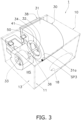
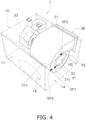
- FIGS. 3 and 4 each illustrate the centrifugal fan 30 housed in the housing space HS in the main body casing 10.
- the centrifugal fan 30 includes a fan casing 31 and a rotor 32.
- the fan casing 31 has a first air inlet 36, a second air inlet 37, and an air outlet 38.
- the rotor 32 is disposed in the fan casing 31.
- the rotor 32 includes a plurality of blades; however, FIGS. 3 and FIG. 4 do not illustrate the blades of the rotor 32.
- the rotor 32 rotates in the fan casing 31, so that the centrifugal fan 30 takes in air through the first air inlet 36 and the second air inlet 37, and blows out the air through the air outlet 38.
- the fan casing 31 includes a first bell mouth 41 defining the first air inlet 36, and a second bell mouth 42 defining the second air inlet 37.
- the air outlet 38 of the centrifugal fan 30 communicates with the opening in the second face 12 of the main body casing 10.
- the first air inlet 36 of the centrifugal fan 30 faces the third face 13, and the second air inlet 37 of the centrifugal fan 30 faces the fourth face 14.
- the fan unit 1 also includes an air flow volume detector 50 configured to detect an air flow volume-equivalent quantity that is equivalent to an air flow volume to be provided by the centrifugal fan 30.
- An air flow volume-equivalent quantity refers to a physical quantity that can be converted into an air flow volume.
- the air flow volume-equivalent quantity is, for example, an air velocity.
- a relationship between an air velocity and an air flow volume to be detected by the air flow volume detector 50 of the fan unit 1 is calculated in advance by experiment or simulation so as to convert, into an air flow volume, an air velocity of air to be provided by the fan unit 1 to which the air flow volume detector 50 is mounted.
- the air flow volume detector 50 is housed in the main body casing 10. In other words, the air flow volume detector 50 is placed in the housing space HS.
- the air flow volume detector 50 is placed on the first bell mouth 41 in order to accurately detect an air flow volume. This embodiment exemplifies the case where the air flow volume detector 50 is placed on the first bell mouth 41. Alternatively, the air flow volume detector 50 may be placed on the second bell mouth 42. Still alternatively, air flow volume detectors 50 may respectively be placed on the first bell mouth 41 and the second bell mouth 42.
- the case where the air flow volume detector 50 is placed on at least one of the first bell mouth 41 or the second bell mouth 42 enables accurate air flow volume detection as compared with, for example, a case where the air flow volume detector 50 is placed on a place different from the first bell mouth 41 and the second bell mouth 42, such as an outer surface of the fan casing 31 or an inner surface of one of the first to sixth faces 11 to 16 of the main body casing 10.
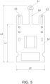
- FIG. 5 illustrates a thermal air velocity sensor which is an example of the air flow volume detector 50.
- the air flow volume detector 50 includes a probe 51, a main body 52, and two temperature measurement units 53.
- the probe 51 of the air flow volume detector 50 includes a heat generator and a temperature sensor.
- An amount of heat dissipated from the probe 51 varies depending on a velocity of air passing through the probe 51.
- the air flow volume detector 50 measures the amount of dissipated heat to detect the air velocity.
- This embodiment exemplifies a case where an amount of dissipated heat is converted into an air velocity and the air velocity is then converted into an air flow volume.
- the air flow volume detector 50 may alternatively be configured to directly convert an amount of dissipated heat into an air flow volume. In this case, the amount of dissipated heat corresponds to an air flow volume-equivalent quantity.
- the probe 51 is disposed on a distal end of an elongate portion extending from a rectangular portion of the main body 52.
- the rectangular portion of the main body 52 is formed of a rectangular plate having a longitudinal length L1 and a lateral length L2.
- the longitudinal length L1 is, for example, 20 mm while the lateral length L2 is, for example, 15 mm.
- the air flow volume detector 50 including the probe 51 has a longitudinal length L3 of, for example, 30 mm.
- the temperature measurement units 53 are located side by side with the probe 51 in between. Each temperature measurement unit 53 is configured to measure a temperature of air passing through the probe 51. An air temperature may vary an amount of heat to be dissipated from the probe 51 even at a fixed air velocity. The air flow volume detector 50 therefore compensates for a value of an air flow volume to be detected by the air flow volume detector 50, with a temperature.
- the centrifugal fan 30 also includes a fan motor 33 disposed outside the fan casing 31 and configured to drive and rotate the rotor 32.
- the fan motor 33 and the rotor 32 are coupled together with a shaft 34.
- the shaft 34 extends from the third face 13 to the fourth face 14 of the main body casing 10.
- the rotor 32 rotates about the shaft 34.
- the fan motor 33 is located nearer to the third face 13 than to the fourth face 14 of the main body casing 10.
- the fan casing 31 is located nearer to the fourth face 14 than the fan motor 33 is.
- the fan casing 31 is located closer to the fourth face 14 with respect to a midpoint between the third face 13 and the fourth face 14. Therefore, the first duct 100 and the second duct 200 are also located nearer to the fourth face 14 than to the third face 13.
- the probe 51 of the air flow volume detector 50 is placed in a current of air that flows into the main body casing 10 through the intake port 18 and then flows into the centrifugal fan 30 through the first air inlet 36. Therefore, the main body 52 of the air flow volume detector 50 is fixed to the fan casing 31.
- This embodiment exemplifies the case where the main body 52 is fixed to the fan casing 31.
- the main body 52 may be fixed to the first bell mouth 41.
- the main body 52 may be fixed to both the fan casing 31 and the first bell mouth 41.
- FIGS. 6 and 7 each illustrate the first bell mouth 41 on which the air flow volume detector 50 is placed.
- FIG. 7 is a schematic sectional view of a part of the fan casing 31, which is taken along line I-I in FIG. 6 .
- FIG. 7 also illustrates a section of the first bell mouth 41 taken along a plane covering the shaft 34.
- the first bell mouth 41 has a surface drawing a convex curve toward the shaft 34. More specifically, the surface of the first bell mouth 41 draws a convex arc toward the shaft 34.
- This embodiment exemplifies the surface of the first bell mouth 41 drawing the convex arc; however, a curve to be drawn by the surface of the first bell mouth 41 is not limited to an arc.
- the surface of the first bell mouth 41 extends inward of the fan casing 31 from a first surface 31a of the fan casing 31 as a distance from the surface of the first bell mouth 41 to the shaft 34 becomes shorter, and reaches the first air inlet 36.
- a first direction DR1 indicates a direction perpendicular to the shaft 34 in the section of the fan casing 31.
- a region AA1 indicates a region between the first air inlet 36 and a position P1 at which the first bell mouth 41 is curved inward of the fan casing 31.
- the region AA1 has an outer side extending to the position P1 and an inner side extending to a position P2 illustrated in FIG. 7 .
- the position P2 is at a boundary between the first bell mouth 41 and the first air inlet 36, and is on an inner periphery of the surface of the first bell mouth 41.
- the probe 51 is located within a range from the position P1 at which the first bell mouth 41 is curved inward of the fan casing 31 to a position corresponding to one-third of a radius R of the first air inlet 36.
- the air flow volume detector 50 is placed such that the main body 52 at least partially overlaps the region AA1 as seen along an axis of the shaft 34 (i.e., as seen in a second direction DR2 illustrated in FIG. 7 ).
- the main body 52 thus placed is fixed to the outer surface, that is, the first surface 31a of the fan casing 31.
- the main body 52 is partially fixed to the first surface 31a.
- the entire main body 52 may be fixed to the first surface 31a as long as the probe 51 is located in a measurement space MS.
- the main body 52 is placed in the region AA1 since the probe 51 is placed in the measurement space MS as illustrated in FIG. 7 .
- the measurement space MS is hatched with dots.
- the measurement space MS extends in the direction toward which the surface of the first bell mouth 41 draws the convex curve, on a normal of the surface of the first bell mouth 41.
- a given point in the measurement space MS has a distance d from the given point to the surface of the first bell mouth 41, and the distance d is larger than 0 and smaller than one-third of the radius R1 of the first air inlet 36.
- a second plane PL covers an inner face 41a of the first bell mouth 41 and extends perpendicularly to the shaft 34.
- the inner face 41a of the first bell mouth 41 belongs to an inner face of the fan casing 31 and is located within the region AA1.
- the measurement space MS extends within a range that covers a part of the second plane PL and is farther from the rotor 32 than from the second plane PL, as seen in the first direction DR1.
- a distance from a farther end edge of the measurement space MS from the rotor 32 to the position P1 is shorter than a length corresponding to one-third of the radius R1 of the first air inlet 36, as seen in the first direction DR1.
- the position P1, at which the first bell mouth 41 is curved inward of the fan casing 31, is on a top portion of the first bell mouth 41.
- the measurement space MS is limited within a range that is nearer to the shaft 34 than the position P1, at which the first bell mouth 41 is curved inward of the fan casing 31, is and is separate from the shaft 34 by a length corresponding to two-third of the radius R1 of the first air inlet 36, as seen in the second direction DR2.
- the position P1, at which the first bell mouth 41 is curved inward of the fan casing 31, is on an outer periphery of the first bell mouth 41. As illustrated in FIG.
- the measurement space MS is a donut-shaped space limited within a range from a position inward of the outer periphery of the first bell mouth 41 to a position inward of an inner periphery of the first bell mouth 41 by the length corresponding to one-third of the radius R1, as seen in the second direction DR2.
- the measurement space MS is limited to a space separate from the first bell mouth 41.
- the distance d from the surface of the first bell mouth 41 to the measurement space MS is larger than 0 and is, for example, 1 mm. Placing the probe 51 at a spot separate from the first bell mouth 41 by 1 mm or more enables accurate conversion from an air velocity into an air flow volume.
- the measurement space MS has a shape of two sectors in the vicinity of the first bell mouth 41, as seen in the section taken along the plane covering the shaft 34.
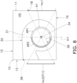
- the first bell mouth 41 is dividable into a first region AR1 (not hatched with oblique lines) and a second region AR2 (hatched with oblique lines), with respect to the intake port 18 of the main body casing 10.
- the probe 51 of the air flow volume detector 50 is located on the normal of the surface of the first bell mouth 41 in the second region AR2 where an air velocity is more stable.
- FIG. 8 illustrates a virtual graphic Fi1 that is line symmetric with the intake port 18 of the main body casing 10 with respect to the shaft 34 defined as a symmetry axis.
- the intake port 18 has a circular shape.
- the intake port 18 extends in parallel with the shaft 34.
- FIG. 8 also illustrates a semicircle hc2 that is line symmetric with the semicircle hc1 with respect to the shaft 34 defined as the symmetry axis.
- the graphic Fi1 is a circular graphic that overlaps the intake port 18 when the intake port 18 turns on the shaft 34 by 180 degrees.
- the first region AR1 is nearer to the intake port 18, and the second region AR2 is nearer to the graphic Fi1.
- FIG. 8 also illustrates a straight line ln1 that passes the shaft 34 and the first bell mouth 41 and is equally separate from the intake port 18 and the graphic Fi1.
- the first region AR1 and the second region AR2 are described with respect to the straight line ln1.
- the first region AR1 is nearer to the intake port 18 than the straight line ln1 on the first bell mouth 41 is.
- the second region AR2 is nearer to the graphic Fi1 than the straight line ln1 on the first bell mouth 41 is.
- the air flow volume detector 50 is placed on the first bell mouth 41. Also in a case where the air flow volume detector 50 is placed on the second bell mouth 42, the air flow volume detector 50 is placed on the second bell mouth 42 in a manner similar to that in the case where the air flow volume detector 50 is placed on the first bell mouth 41. In the case where the air flow volume detector 50 is placed on the second bell mouth 42, the probe 51 of the air flow volume detector 50 is placed in a current of air that flows into the main body casing 10 through the intake port 18 and then flows into the centrifugal fan 30 through the second air inlet 37.
- the main body 52 of the air flow volume detector 50 is fixed to the fan casing 31.
- the main body 52 may be fixed to the first bell mouth 41.
- the main body 52 may be fixed to both the fan casing 31 and the first bell mouth 41.
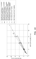
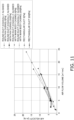
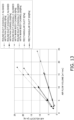
- FIGS. 9 to 13 illustrate relationships between an air velocity and an air flow volume measured with the air flow volume detector 50 mounted at different positions of the fan casing 31.
- FIG. 9 is a graph of the relationship between an air velocity and an air flow volume measured by the air flow volume detector 50 mounted at the foregoing position illustrated in FIG. 3 .
- FIG. 10 is a graph of the relationship between an air velocity and an air flow volume measured by the air flow volume detector 50 mounted at a first spot SP1 illustrated in FIG. 4 .
- FIG. 11 is a graph of the relationship between an air velocity and an air flow volume measured by the air flow volume detector 50 mounted at a second spot SP2 illustrated in FIG. 4 .
- FIG. 9 is a graph of the relationship between an air velocity and an air flow volume measured by the air flow volume detector 50 mounted at different positions of the fan casing 31.
- FIG. 9 is a graph of the relationship between an air velocity and an air flow volume measured by the air flow volume detector 50 mounted at the foregoing position illustrated in FIG. 3 .
- FIG. 12 is a graph of the relationship between an air velocity and an air flow volume measured by the air flow volume detector 50 mounted at a third spot SP3 illustrated in FIG. 3 .
- FIG. 13 is a graph of the relationship between an air velocity and an air flow volume measured by the air flow volume detector 50 mounted at a fourth spot SP4 illustrated in FIG. 4 .
- Each of the probe 51 of the air flow volume detector 50 mounted at the first spot SP1 in FIG. 4 and the probe 51 of the air flow volume detector 50 mounted at the second spot SP2 in FIG. 4 is placed in the measurement space MS, which is similar to the probe 51 of the air flow volume detector 50 illustrated in FIG. 3 in this respect.
- the foregoing position of the air flow volume detector 50 illustrated in FIG. 3 is farthest from the intake port 18 in the first bell mouth 41.
- the first spot SP1 is nearest to the intake port 18 in the second bell mouth 42.
- the second spot SP2 is nearest to the fifth face 15 in the second bell mouth 42.
- the third spot SP3 is nearest to the intake port 18 in the first surface 31a of the fan casing 31.
- the fourth spot SP4 is nearest to the intake port 18 in a second surface 31c of the fan casing 31.
- the first duct 100 used for the measurements is a rectangular duct and a round duct each having a length L11 of 500 mm.
- the round duct has a diameter of 200 mm.
- the rectangular duct is equal in size to the first face 11 of the main body casing 10. In the case where the rectangular duct is used as the first duct 100, the portion corresponding to the first face 11 where the round duct is to be mounted is wholly open when the rectangular duct is removed.
- the main body casing 10 has a length L12 of 340 mm, a width L13 of 520 mm, and a height L14 of 300 mm.
- a chain line indicates a result of measurement made on conditions that the first duct 100 is the round duct, a static pressure outside the fan unit 1 is 0 Pa, and the round duct is coaxially aligned with the fan casing 31.
- a solid line combined with square plots indicates a result of measurement made on conditions that the first duct 100 is the round duct, a static pressure outside the fan unit 1 is 200 Pa, and the round duct is coaxially aligned with the fan casing 31.
- a chain double-dashed line combined with triangular plots indicates a result of measurement made on conditions that the first duct 100 is the round duct, a static pressure outside the fan unit 1 is 0 Pa, and the round duct is coaxially aligned with the main body casing 10.
- a solid line combined with "x" plots indicates a result of measurement made on conditions that the first duct 100 is the round duct, a static pressure outside the fan unit 1 is 200 Pa, and the round duct is coaxially aligned with the main body casing 10.
- a broken line combined with asterisk plots indicates a result of measurement made on conditions that the first duct 100 is the rectangular duct and a static pressure outside the fan unit 1 is 0 Pa.
- a solid line combined with circular plots indicates a result of measurement made on conditions that the first duct 100 is the rectangular duct and a static pressure outside the fan unit 1 is 200 Pa.
- the gradients of the respective lines largely differ in the case of the round duct and in the case of the rectangular duct. Therefore, in the case where the air flow volume detector 50 is placed on the first bell mouth 41 or the second bell mouth 42, the relationship between the air velocity and the air flow volume is kept regardless of the shape of the intake port 18 (i.e., a sectional shape of the flow path in the first duct 100). In contrast to this, in the case where the air flow volume detector 50 is placed on the surface of the fan casing 31 far from the bell mouth, the relationship between the air velocity and the air flow volume is significantly affected by the shape of the intake port 18 (i.e., the sectional shape of the flow path in the first duct 100) as illustrated in FIGS. 12 and 13 .
- the air flow volume detector 50 is fixed such that the probe 51 of the air flow volume detector 50 is placed in the measurement space MS of the first bell mouth 41 or second bell mouth 42.
- This configuration allows the fan unit 1 not to change conversion conditions from an air velocity into an air flow volume even when the sectional shape of the flow path in the first duct 100 is changed.
- first bell mouth 41 and the second bell mouth 42 do not protrude from the first surface 31a and the second surface 31c of the fan casing 31, respectively, with reference to FIG. 7 .
- a first bell mouth 43 and a second bell mouth 44 may protrude from a first surface 31a and a second surface 31c of a fan casing 31, respectively.
- FIG. 14 illustrates the first bell mouth 43 (the second bell mouth 44) on which an air flow volume detector 50 is placed.
- FIG. 14 also illustrates a section of the first bell mouth 43 (the second bell mouth 44) taken along a plane covering a shaft 34.
- the first bell mouth 43 (the second bell mouth 44) has a surface drawing a convex curve toward the shaft 34. More specifically, the surface of the first bell mouth 43 (the second bell mouth 44) draws a convex arc toward the shaft 34.
- FIG. 14 illustrates the first bell mouth 43 (the second bell mouth 44) on which an air flow volume detector 50 is placed.
- FIG. 14 also illustrates a section of the first bell mouth 43 (the second bell mouth 44) taken along a plane covering a shaft 34.
- the first bell mouth 43 (the second bell mouth 44) has a surface drawing a convex curve toward the shaft 34. More specifically, the surface of the first bell mouth 43 (the second bell mouth 44) draws a convex arc toward the shaft 34.
- the surface of the first bell mouth 43 protrudes outward of the fan casing 31 from the first surface 31a (the second surface 31c) of the fan casing 31 as a distance from the surface of the first bell mouth 43 (the second bell mouth 44) to the shaft 34 becomes smaller, reaches a top portion PP of the first bell mouth 43 (the second bell mouth 44), extends inward of the fan casing 31, and reaches a first air inlet 36 (a second air inlet 37).
- a region AA2 has an outer side extending to a position P4 that is at a boundary between the surface of the first bell mouth 43 (the second bell mouth 44) and the first surface 31a of the fan casing 31, and an inner side extending to a position P3 illustrated in FIG. 14 .
- the position P4 is on an outer periphery of the first bell mouth 43 (the second bell mouth 44).
- the position P3 is at a boundary between the surface of the first bell mouth 43 (the second bell mouth 44) and the first air inlet 36 (the second air inlet 37), and on an inner periphery of the surface of the first bell mouth 43 (the second bell mouth 44). As illustrated in FIG.
- a measurement space MS is a donut-shaped space limited within a range from a position outward of the outer periphery of the first bell mouth 43 (the second bell mouth 44) by a length corresponding to one-third of a radius R1 of the first air inlet 36 (the second air inlet 37) to a position inward of the inner periphery of the first bell mouth 43 (the second bell mouth 44) by the length corresponding to one-third of the radius R1, as seen in a second direction DR2.
- the air flow volume detector 50 is placed such that a main body 52 at least partially overlaps the region AA2 as seen in the second direction DR2. It should be noted that the entire main body 52 may be fixed to the first surface 31a as long as a probe 51 is located in the measurement space MS.
- the main body 52 is placed in the region AA2 since the probe 51 is placed in the measurement space MS as illustrated in FIG. 14 .
- the measurement space MS is hatched with dots.
- the measurement space MS extends in the direction toward which the surface of the first bell mouth 41 draws the convex curve, on a normal of the surface of the first bell mouth 41.
- a given point in the measurement space MS has a distance d from the given point to the surface of the first bell mouth 41, and the distance d is larger than 0 and smaller than one-third of the radius R1 of the first air inlet 36.
- a second plane PL covers an inner face 43a (an inner face 44a) of the first bell mouth 43 (the second bell mouth 44) and extends perpendicularly to the shaft 34.
- the inner face 43a, 44a of the first bell mouth 41 belongs to an inner face of the fan casing 31 and is located within the region AA2.
- the measurement space MS extends within a range that covers a part of the second plane PL and is farther from a rotor 32 than from the second plane PL, as seen in a first direction DR1.
- a distance from a farther end edge of the measurement space MS from the rotor 32 to the top portion PP is shorter than a length corresponding to one-third of the radius R1 of the first air inlet 36 (the second air inlet 37), as seen in the first direction DR1.
- the measurement space MS is limited within a range corresponding to one-third of the radius R1 from the farther end edge of the measurement space MS from the shaft 34 to the boundary P4 between the surface of the first bell mouth 43 (the second bell mouth 44) and the fan casing 31, as seen in the second direction DR2.
- the measurement space MS is limited within a range corresponding to one-third of the radius toward the shaft 34 from a nearer end edge of the measurement space MS to the shaft 34 to the boundary P3 between the surface of the first bell mouth 43 (the second bell mouth 44) and the first air inlet 36 (the second air inlet 37), as seen in the second direction DR2.
- the measurement space MS is limited to a space separate from the first bell mouth 43 (the second bell mouth 44).
- the measurement space MS has a shape of two half rings in the vicinity of the first bell mouth 41 (the second bell mouth 44), as seen in the section taken along the plane covering the shaft 34.
- the first bell mouth 43 (the second bell mouth 44) is also dividable into a first region AR1 and a second region AR2 with respect to an intake port 18 of a main body casing 10, which is similar to the first bell mouth 41 illustrated in FIG. 8 in this respect.
- the air flow volume detector 50 is placed in the second region AR2 far from the intake port 18.
- the foregoing embodiment concerns the case where the centrifugal fan 30 includes two air inlets, that is, the first air inlet 36 and the second air inlet 37.
- the centrifugal fan 30 is not limited to that including the first air inlet 36 and the second air inlet 37.
- the technique of the foregoing embodiment is also applicable to a centrifugal fan including one air inlet.
- the foregoing embodiment concerns the case where the main body casing 10 has the rectangular parallelepiped-base shape.
- the shape of the main body casing 10 is not limited to that described in the foregoing embodiment.
- the main body casing 10 may have a cubic-base shape or a cylindrical-base shape.
- the foregoing embodiment concerns the case where the fan motor 33 is placed in the housing space HS in the main body casing 10.
- the fan motor 33 may alternatively be placed outside the main body casing 10.
- the aspect that the centrifugal fan 30 is placed in the main body casing 10 also involves a case where the fan motor 33 is placed outside the main body casing 10 and the fan casing 31 is placed in the main body casing 10.
- the fan casing 31 includes the first bell mouth 41, 43 defining the first air inlet 36 through which air in the main body casing 10 flows into the fan casing 31, and the second bell mouth 42, 44 defining the second air inlet 37 through which air in the main body casing 10 flows into the fan casing 31.
- the main body 52 of the air flow volume detector 50 is fixed to at least one of the fan casing 31, the first bell mouth 41, 43, or the second bell mouth 42, 44. In the fan unit 1, a current of air is stable in the vicinity of the first bell mouth 41 and the second bell mouth 42.
- the probe 51 is located on the normal of the surface of at least one of the first bell mouth 41 or the second bell mouth 42 in the direction toward which the surface of at least one of the first bell mouth 41 or the second bell mouth 42 draws the convex curve.
- the probe 51 has the distance d from the probe 51 to the surface of at least one of the first bell mouth 41 or the second bell mouth 42, and the distance d is larger than 0 and smaller than one-third of the radius R1 of the first air inlet 36.
- the probe 51 placed at such a spot is capable of detecting an air flow volume-equivalent quantity in a stable current of air. Therefore, the air flow volume detector 50 including the probe 51 is capable of accurately detecting an air flow volume-equivalent quantity.
- the probe 51 is located on the normal of the surface of the first bell mouth 41 (the second bell mouth 42). In addition, the probe 51 has the distance d from the probe 51 to the surface of the first bell mouth 41 (the second bell mouth 42). The distance d is larger than 0 and smaller than one-third of the radius R1 of the first air inlet 36.
- the probe 51 is placed in the measurement space MS where a current of air is stable.
- the fan unit 1 including the probe 51 placed in the measurement space MS where a current of air is stable is capable of more accurately detecting an air flow volume-equivalent quantity, as compared with another fan unit including a probe 51 placed at a spot different from the measurement space MS.
- the probe 51 is located on the normal of the surface of the first bell mouth 43 (the second bell mouth 44). In addition, the probe 51 has the distance d from the probe 51 to the surface of the first bell mouth 43 (the second bell mouth 44). The distance d is larger than 0 and smaller than one-third of the radius R1 of the first air inlet 36.
- the probe 51 is placed in the measurement space MS where a current of air is stable.
- the fan unit 1 including the probe 51 placed in the measurement space MS where a current of air is stable is capable of more accurately detecting an air flow volume-equivalent quantity, as compared with another fan unit including a probe 51 placed at a spot different from the measurement space MS.
- Patent Literature 1 JP 2019-167828 A
Landscapes
- Engineering & Computer Science (AREA)
- Mechanical Engineering (AREA)
- General Engineering & Computer Science (AREA)
- Structures Of Non-Positive Displacement Pumps (AREA)
- Control Of Positive-Displacement Air Blowers (AREA)
Abstract
Description
- The present disclosure relates to a fan unit including a centrifugal fan that is housed in a main body casing.
- Patent Literature 1 (
JP 2019-167828 A - In a case where an air flow volume is detected based on an air velocity in a duct as disclosed in
Patent Literature 1, it is necessary to allocate straight portions in front of and behind a measurement site, in order to measure the air flow volume accurately. In actual construction work, a duct is bent for installation in accordance with a situation of an attic; therefore, it is less likely to adequately allocate straight portions in front of and behind a measurement site, which may lower air flow volume measurement accuracy. On the other hand, measuring an air flow volume in a fan unit is susceptible to influences of a structural component such as a motor, a distance from a unit casing, and the like. It is consequently difficult to detect an air flow volume. - There is a need for a fan unit connected to a duct to accurately detect an air flow volume in the fan unit.
- A first aspect is directed to a fan unit including a centrifugal fan, an air flow volume detector, and a main body casing. The centrifugal fan includes a fan casing and a rotor disposed in the fan casing and rotatable about a shaft. The air flow volume detector includes a main body and a probe configured to detect an air flow volume-equivalent quantity that is equivalent to an air flow volume to be provided by the centrifugal fan. The main body casing houses the centrifugal fan and the air flow volume detector. The fan casing includes a bell mouth defining an air inlet through which air in the main body casing flows into the fan casing. The bell mouth has a surface drawing a convex curve toward the shaft as seen in a section taken along a plane covering the shaft. The main body is fixed to at least one of the fan casing or the bell mouth. The probe is located on a normal of the surface of the bell mouth in a direction toward which the surface of the bell mouth protrudes, and a distance from the probe to the surface of the bell mouth is larger than 0 and smaller than one-third of a radius of the air inlet.
- In the fan unit according to the first aspect, a current of air is stable in the vicinity of the bell mouth. The probe is located on the normal of the surface of the bell mouth in the direction toward which the surface of the bell mouth protrudes, and the distance from the probe to the surface of the bell mouth is larger than 0 and smaller than one-third of the radius of the air inlet. The probe is therefore capable of detecting an air flow volume-equivalent quantity in a stable current of air. Therefore, the air flow volume detector including the probe is capable of accurately detecting an air flow volume-equivalent quantity.
- A second aspect is directed to the fan unit according to the first aspect, in which the surface of the bell mouth extends inward of the fan casing from a surface of the fan casing as a distance from the surface of the bell mouth to the shaft becomes shorter, and reaches the air inlet.
- In the fan unit according to the second aspect, the probe is located in the space where a current of air is stable. The fan unit according to the second aspect, which includes the probe located in the space where a current of air is stable, is capable of more accurately detecting an air flow volume-equivalent quantity, as compared with another fan unit including a probe placed at a spot different from the foregoing space.
- A third aspect is directed to the fan unit according to the first aspect, in which the surface of the bell mouth protrudes outward of the fan casing from a surface of the fan casing as a distance from the surface of the bell mouth to the shaft becomes shorter, reaches a top portion of the bell mouth, extends inward of the fan casing, and reaches the air inlet.
- In the fan unit according to the third aspect, the probe is located in the space where a current of air is stable. The fan unit according to the third aspect, which includes the probe located in the space where a current of air is stable, is capable of more accurately detecting an air flow volume-equivalent quantity, as compared with another fan unit including a probe placed at a spot different from the foregoing space.
- A fourth aspect is directed to the fan unit according to any of the first to third aspects, in which the main body casing includes an intake port through which air flows into the main body casing. The air flow volume detector is placed in a current of air flowing into the main body casing through the intake port and flowing into the centrifugal fan through the air inlet.
- A fifth aspect is directed to the fan unit according to the fourth aspect, in which, in consideration of a virtual graphic that is line symmetric with the intake port of the main body casing with respect to the shaft defined as a symmetry axis, the bell mouth is divided into a first region near the intake port and a second region near the virtual graphic, and the air flow volume detector is placed in the second region.
- A sixth aspect is directed to the fan unit according to any of the first to fifth aspects, in which the air flow volume detector includes an air velocity sensor configured to detect, as the air flow volume-equivalent quantity, an air velocity of air flowing through the air inlet.
-
-
FIG. 1 is a schematic top view of a fan unit and a duct according to an embodiment. -
FIG. 2 is a schematic side view of the fan unit and the duct according to the embodiment. -
FIG. 3 is a perspective view of a centrifugal fan and an air flow volume detector in a main body casing of the fan unit. -
FIG. 4 is a perspective view of the centrifugal fan in the main body casing of the fan unit. -
FIG. 5 is a plan view of an example of the air flow volume detector. -
FIG. 6 is a schematic side view of the centrifugal fan, which illustrates a placement position of the air flow volume detector. -
FIG. 7 is a schematic sectional view of a part of the centrifugal fan, which is taken along line I-I inFIG. 6 . -
FIG. 8 is a schematic side view of the centrifugal fan, which illustrates a preferable placement position of the air flow volume detector. -
FIG. 9 is a graph of a relationship between an air velocity and an air flow volume detected by the air flow volume detector placed on a first bell mouth. -
FIG. 10 is a graph of a relationship between an air velocity and an air flow volume detected by the air flow volume detector placed on a first surface of a fan casing. -
FIG. 11 is a graph of a relationship between an air velocity and an air flow volume detected by the air flow volume detector placed on a second bell mouth. -
FIG. 12 is a graph of a relationship between an air velocity and an air flow volume detected by the air flow volume detector placed at another position of the second bell mouth. -
FIG. 13 is a graph of a relationship between an air velocity and an air flow volume detected by the air flow volume detector placed on a second surface of the fan casing. -
FIG. 14 is a schematic sectional view of a part of a centrifugal fan according to Modification A. - As illustrated in
FIGS. 1 and2 , afan unit 1 is, in use, connected to, for example, afirst duct 100 and asecond duct 200.FIG. 1 is a top view of thefan unit 1, thefirst duct 100, and thesecond duct 200.FIG. 2 is a side view of thefan unit 1, thefirst duct 100, and thesecond duct 200. Thefan unit 1 is configured to provide air from thefirst duct 100 to thesecond duct 200. Each of thefirst duct 100 and thesecond duct 200 illustrated inFIGS. 1 and2 is a round duct. Accordingly, each of thefirst duct 100 and thesecond duct 200 has a circular sectional shape taken along a plane orthogonal to a flow path. - The
fan unit 1 includes amain body casing 10. Themain body casing 10 has a rectangular parallelepiped-base shape. Themain body casing 10 has first tosixth faces 11 to 16 that define a housing space HS (seeFIGS. 1 to 4 ). Thefirst duct 100 is connected to thefirst face 11. Thefirst face 11 has an opening to which thefirst duct 100 is connected, and this opening serves as an intake port 18 (seeFIGS. 3 and4 ) of themain body casing 10. Thesecond duct 200 is connected to thesecond face 12. Thesecond face 12 has an opening to which thesecond duct 200 is connected, and this opening serves as a blow-out port 19 (seeFIG. 1 ) of themain body casing 10. In thefan unit 1 illustrated inFIGS. 1 and2 , thefirst face 11,second face 12,third face 13, andfourth face 14 define side surfaces of themain body casing 10, thefifth face 15 defines a top surface of themain body casing 10, and thesixth face 16 defines a bottom surface of themain body casing 10. For convenience of the description, thefifth face 15 is regarded as the top surface, and thesixth face 16 is regarded as the bottom surface. However, the first to sixth faces 11 to 16 are not necessarily oriented as illustrated inFIGS. 1 and2 . The orientation of the first to sixth faces 11 to 16 of thefan unit 1 is appropriately set in use. - The
fan unit 1 also includes acentrifugal fan 30. Thecentrifugal fan 30 for use in thefan unit 1 is, for example, a sirocco fan. Thecentrifugal fan 30 is housed in themain body casing 10.FIGS. 3 and4 each illustrate thecentrifugal fan 30 housed in the housing space HS in themain body casing 10. Thecentrifugal fan 30 includes afan casing 31 and arotor 32. Thefan casing 31 has afirst air inlet 36, asecond air inlet 37, and anair outlet 38. Therotor 32 is disposed in thefan casing 31. Therotor 32 includes a plurality of blades; however,FIGS. 3 andFIG. 4 do not illustrate the blades of therotor 32. Therotor 32 rotates in thefan casing 31, so that thecentrifugal fan 30 takes in air through thefirst air inlet 36 and thesecond air inlet 37, and blows out the air through theair outlet 38. Thefan casing 31 includes afirst bell mouth 41 defining thefirst air inlet 36, and asecond bell mouth 42 defining thesecond air inlet 37. In the housing space HS, theair outlet 38 of thecentrifugal fan 30 communicates with the opening in thesecond face 12 of themain body casing 10. Also in the housing space HS, thefirst air inlet 36 of thecentrifugal fan 30 faces thethird face 13, and thesecond air inlet 37 of thecentrifugal fan 30 faces thefourth face 14. - The
fan unit 1 also includes an airflow volume detector 50 configured to detect an air flow volume-equivalent quantity that is equivalent to an air flow volume to be provided by thecentrifugal fan 30. An air flow volume-equivalent quantity refers to a physical quantity that can be converted into an air flow volume. The air flow volume-equivalent quantity is, for example, an air velocity. For example, a relationship between an air velocity and an air flow volume to be detected by the airflow volume detector 50 of thefan unit 1 is calculated in advance by experiment or simulation so as to convert, into an air flow volume, an air velocity of air to be provided by thefan unit 1 to which the airflow volume detector 50 is mounted. In order to convert an air velocity of thefan unit 1 into an air flow volume, for example, a relational expression between an air velocity and an air flow volume may be established in advance or a conversion table for converting an air velocity into an air flow volume may be prepared in advance. The airflow volume detector 50 is housed in themain body casing 10. In other words, the airflow volume detector 50 is placed in the housing space HS. The airflow volume detector 50 is placed on thefirst bell mouth 41 in order to accurately detect an air flow volume. This embodiment exemplifies the case where the airflow volume detector 50 is placed on thefirst bell mouth 41. Alternatively, the airflow volume detector 50 may be placed on thesecond bell mouth 42. Still alternatively, airflow volume detectors 50 may respectively be placed on thefirst bell mouth 41 and thesecond bell mouth 42. The case where the airflow volume detector 50 is placed on at least one of thefirst bell mouth 41 or thesecond bell mouth 42 enables accurate air flow volume detection as compared with, for example, a case where the airflow volume detector 50 is placed on a place different from thefirst bell mouth 41 and thesecond bell mouth 42, such as an outer surface of thefan casing 31 or an inner surface of one of the first to sixth faces 11 to 16 of themain body casing 10. -
FIG. 5 illustrates a thermal air velocity sensor which is an example of the airflow volume detector 50. The airflow volume detector 50 includes aprobe 51, amain body 52, and twotemperature measurement units 53. Theprobe 51 of the airflow volume detector 50 includes a heat generator and a temperature sensor. An amount of heat dissipated from theprobe 51 varies depending on a velocity of air passing through theprobe 51. The airflow volume detector 50 measures the amount of dissipated heat to detect the air velocity. This embodiment exemplifies a case where an amount of dissipated heat is converted into an air velocity and the air velocity is then converted into an air flow volume. The airflow volume detector 50 may alternatively be configured to directly convert an amount of dissipated heat into an air flow volume. In this case, the amount of dissipated heat corresponds to an air flow volume-equivalent quantity. - The
probe 51 is disposed on a distal end of an elongate portion extending from a rectangular portion of themain body 52. The rectangular portion of themain body 52 is formed of a rectangular plate having a longitudinal length L1 and a lateral length L2. The longitudinal length L1 is, for example, 20 mm while the lateral length L2 is, for example, 15 mm. The airflow volume detector 50 including theprobe 51 has a longitudinal length L3 of, for example, 30 mm. - The
temperature measurement units 53 are located side by side with theprobe 51 in between. Eachtemperature measurement unit 53 is configured to measure a temperature of air passing through theprobe 51. An air temperature may vary an amount of heat to be dissipated from theprobe 51 even at a fixed air velocity. The airflow volume detector 50 therefore compensates for a value of an air flow volume to be detected by the airflow volume detector 50, with a temperature. - The
centrifugal fan 30 also includes afan motor 33 disposed outside thefan casing 31 and configured to drive and rotate therotor 32. Thefan motor 33 and therotor 32 are coupled together with ashaft 34. Theshaft 34 extends from thethird face 13 to thefourth face 14 of themain body casing 10. Therotor 32 rotates about theshaft 34. Thefan motor 33 is located nearer to thethird face 13 than to thefourth face 14 of themain body casing 10. Thefan casing 31 is located nearer to thefourth face 14 than thefan motor 33 is. Thefan casing 31 is located closer to thefourth face 14 with respect to a midpoint between thethird face 13 and thefourth face 14. Therefore, thefirst duct 100 and thesecond duct 200 are also located nearer to thefourth face 14 than to thethird face 13. - The
probe 51 of the airflow volume detector 50 is placed in a current of air that flows into the main body casing 10 through theintake port 18 and then flows into thecentrifugal fan 30 through thefirst air inlet 36. Therefore, themain body 52 of the airflow volume detector 50 is fixed to thefan casing 31. This embodiment exemplifies the case where themain body 52 is fixed to thefan casing 31. Alternatively, themain body 52 may be fixed to thefirst bell mouth 41. Still alternatively, themain body 52 may be fixed to both thefan casing 31 and thefirst bell mouth 41. -
FIGS. 6 and7 each illustrate thefirst bell mouth 41 on which the airflow volume detector 50 is placed.FIG. 7 is a schematic sectional view of a part of thefan casing 31, which is taken along line I-I inFIG. 6 .FIG. 7 also illustrates a section of thefirst bell mouth 41 taken along a plane covering theshaft 34. As illustrated inFIG. 7 , thefirst bell mouth 41 has a surface drawing a convex curve toward theshaft 34. More specifically, the surface of thefirst bell mouth 41 draws a convex arc toward theshaft 34. This embodiment exemplifies the surface of thefirst bell mouth 41 drawing the convex arc; however, a curve to be drawn by the surface of thefirst bell mouth 41 is not limited to an arc. The surface of thefirst bell mouth 41 extends inward of the fan casing 31 from afirst surface 31a of thefan casing 31 as a distance from the surface of thefirst bell mouth 41 to theshaft 34 becomes shorter, and reaches thefirst air inlet 36. - In
FIG. 7 , a first direction DR1 indicates a direction perpendicular to theshaft 34 in the section of thefan casing 31. Also inFIG. 7 , a region AA1 indicates a region between thefirst air inlet 36 and a position P1 at which thefirst bell mouth 41 is curved inward of thefan casing 31. The region AA1 has an outer side extending to the position P1 and an inner side extending to a position P2 illustrated inFIG. 7 . The position P2 is at a boundary between thefirst bell mouth 41 and thefirst air inlet 36, and is on an inner periphery of the surface of thefirst bell mouth 41. In the first direction DR1, theprobe 51 is located within a range from the position P1 at which thefirst bell mouth 41 is curved inward of thefan casing 31 to a position corresponding to one-third of a radius R of thefirst air inlet 36. The airflow volume detector 50 is placed such that themain body 52 at least partially overlaps the region AA1 as seen along an axis of the shaft 34 (i.e., as seen in a second direction DR2 illustrated inFIG. 7 ). Themain body 52 thus placed is fixed to the outer surface, that is, thefirst surface 31a of thefan casing 31. In this embodiment, themain body 52 is partially fixed to thefirst surface 31a. Alternatively, the entiremain body 52 may be fixed to thefirst surface 31a as long as theprobe 51 is located in a measurement space MS. - The
main body 52 is placed in the region AA1 since theprobe 51 is placed in the measurement space MS as illustrated inFIG. 7 . InFIG. 7 , the measurement space MS is hatched with dots. The measurement space MS extends in the direction toward which the surface of thefirst bell mouth 41 draws the convex curve, on a normal of the surface of thefirst bell mouth 41. A given point in the measurement space MS has a distance d from the given point to the surface of thefirst bell mouth 41, and the distance d is larger than 0 and smaller than one-third of the radius R1 of thefirst air inlet 36. A second plane PL covers aninner face 41a of thefirst bell mouth 41 and extends perpendicularly to theshaft 34. Theinner face 41a of thefirst bell mouth 41 belongs to an inner face of thefan casing 31 and is located within the region AA1. The measurement space MS extends within a range that covers a part of the second plane PL and is farther from therotor 32 than from the second plane PL, as seen in the first direction DR1. A distance from a farther end edge of the measurement space MS from therotor 32 to the position P1 is shorter than a length corresponding to one-third of the radius R1 of thefirst air inlet 36, as seen in the first direction DR1. The position P1, at which thefirst bell mouth 41 is curved inward of thefan casing 31, is on a top portion of thefirst bell mouth 41. The measurement space MS is limited within a range that is nearer to theshaft 34 than the position P1, at which thefirst bell mouth 41 is curved inward of thefan casing 31, is and is separate from theshaft 34 by a length corresponding to two-third of the radius R1 of thefirst air inlet 36, as seen in the second direction DR2. The position P1, at which thefirst bell mouth 41 is curved inward of thefan casing 31, is on an outer periphery of thefirst bell mouth 41. As illustrated inFIG. 7 , therefore, the measurement space MS is a donut-shaped space limited within a range from a position inward of the outer periphery of thefirst bell mouth 41 to a position inward of an inner periphery of thefirst bell mouth 41 by the length corresponding to one-third of the radius R1, as seen in the second direction DR2. In addition, the measurement space MS is limited to a space separate from thefirst bell mouth 41. The distance d from the surface of thefirst bell mouth 41 to the measurement space MS is larger than 0 and is, for example, 1 mm. Placing theprobe 51 at a spot separate from thefirst bell mouth 41 by 1 mm or more enables accurate conversion from an air velocity into an air flow volume. As illustrated inFIG. 7 , the measurement space MS has a shape of two sectors in the vicinity of thefirst bell mouth 41, as seen in the section taken along the plane covering theshaft 34. - As illustrated in
FIG. 8 , thefirst bell mouth 41 is dividable into a first region AR1 (not hatched with oblique lines) and a second region AR2 (hatched with oblique lines), with respect to theintake port 18 of themain body casing 10. Preferably, theprobe 51 of the airflow volume detector 50 is located on the normal of the surface of thefirst bell mouth 41 in the second region AR2 where an air velocity is more stable. -
FIG. 8 illustrates a virtual graphic Fi1 that is line symmetric with theintake port 18 of the main body casing 10 with respect to theshaft 34 defined as a symmetry axis. As illustrated inFIG. 3 , theintake port 18 has a circular shape. Theintake port 18 extends in parallel with theshaft 34. When theintake port 18 is seen from the third face 13 (seeFIG. 3 ) of thecentrifugal fan 30 along the axis of theshaft 34, a nearer semicircle hc1 to thethird face 13 appears.FIG. 8 also illustrates a semicircle hc2 that is line symmetric with the semicircle hc1 with respect to theshaft 34 defined as the symmetry axis. The graphic Fi1 is a circular graphic that overlaps theintake port 18 when theintake port 18 turns on theshaft 34 by 180 degrees. The first region AR1 is nearer to theintake port 18, and the second region AR2 is nearer to the graphic Fi1.FIG. 8 also illustrates a straight line ln1 that passes theshaft 34 and thefirst bell mouth 41 and is equally separate from theintake port 18 and the graphic Fi1. The first region AR1 and the second region AR2 are described with respect to the straight line ln1. The first region AR1 is nearer to theintake port 18 than the straight line ln1 on thefirst bell mouth 41 is. The second region AR2 is nearer to the graphic Fi1 than the straight line ln1 on thefirst bell mouth 41 is. - According to the foregoing exemplary description on the placement position of the air
flow volume detector 50, the airflow volume detector 50 is placed on thefirst bell mouth 41. Also in a case where the airflow volume detector 50 is placed on thesecond bell mouth 42, the airflow volume detector 50 is placed on thesecond bell mouth 42 in a manner similar to that in the case where the airflow volume detector 50 is placed on thefirst bell mouth 41. In the case where the airflow volume detector 50 is placed on thesecond bell mouth 42, theprobe 51 of the airflow volume detector 50 is placed in a current of air that flows into the main body casing 10 through theintake port 18 and then flows into thecentrifugal fan 30 through thesecond air inlet 37. In the case where the airflow volume detector 50 is placed on thesecond bell mouth 42, themain body 52 of the airflow volume detector 50 is fixed to thefan casing 31. Alternatively, themain body 52 may be fixed to thefirst bell mouth 41. Still alternatively, themain body 52 may be fixed to both thefan casing 31 and thefirst bell mouth 41. -
FIGS. 9 to 13 illustrate relationships between an air velocity and an air flow volume measured with the airflow volume detector 50 mounted at different positions of thefan casing 31.FIG. 9 is a graph of the relationship between an air velocity and an air flow volume measured by the airflow volume detector 50 mounted at the foregoing position illustrated inFIG. 3 .FIG. 10 is a graph of the relationship between an air velocity and an air flow volume measured by the airflow volume detector 50 mounted at a first spot SP1 illustrated inFIG. 4 .FIG. 11 is a graph of the relationship between an air velocity and an air flow volume measured by the airflow volume detector 50 mounted at a second spot SP2 illustrated inFIG. 4 .FIG. 12 is a graph of the relationship between an air velocity and an air flow volume measured by the airflow volume detector 50 mounted at a third spot SP3 illustrated inFIG. 3 .FIG. 13 is a graph of the relationship between an air velocity and an air flow volume measured by the airflow volume detector 50 mounted at a fourth spot SP4 illustrated inFIG. 4 . Each of theprobe 51 of the airflow volume detector 50 mounted at the first spot SP1 inFIG. 4 and theprobe 51 of the airflow volume detector 50 mounted at the second spot SP2 inFIG. 4 is placed in the measurement space MS, which is similar to theprobe 51 of the airflow volume detector 50 illustrated inFIG. 3 in this respect. - The foregoing position of the air
flow volume detector 50 illustrated inFIG. 3 is farthest from theintake port 18 in thefirst bell mouth 41. The first spot SP1 is nearest to theintake port 18 in thesecond bell mouth 42. The second spot SP2 is nearest to thefifth face 15 in thesecond bell mouth 42. The third spot SP3 is nearest to theintake port 18 in thefirst surface 31a of thefan casing 31. The fourth spot SP4 is nearest to theintake port 18 in asecond surface 31c of thefan casing 31. - Measurements are made in a state in which the
second duct 200 is removed, in order to obtain the graphs ofFIGS. 9 to 13 . Thefirst duct 100 used for the measurements is a rectangular duct and a round duct each having a length L11 of 500 mm. The round duct has a diameter of 200 mm. The rectangular duct is equal in size to thefirst face 11 of themain body casing 10. In the case where the rectangular duct is used as thefirst duct 100, the portion corresponding to thefirst face 11 where the round duct is to be mounted is wholly open when the rectangular duct is removed. Themain body casing 10 has a length L12 of 340 mm, a width L13 of 520 mm, and a height L14 of 300 mm. In each of the graphs ofFIGS. 9 to 13 , a chain line indicates a result of measurement made on conditions that thefirst duct 100 is the round duct, a static pressure outside thefan unit 1 is 0 Pa, and the round duct is coaxially aligned with thefan casing 31. A solid line combined with square plots indicates a result of measurement made on conditions that thefirst duct 100 is the round duct, a static pressure outside thefan unit 1 is 200 Pa, and the round duct is coaxially aligned with thefan casing 31. A chain double-dashed line combined with triangular plots indicates a result of measurement made on conditions that thefirst duct 100 is the round duct, a static pressure outside thefan unit 1 is 0 Pa, and the round duct is coaxially aligned with themain body casing 10. A solid line combined with "x" plots indicates a result of measurement made on conditions that thefirst duct 100 is the round duct, a static pressure outside thefan unit 1 is 200 Pa, and the round duct is coaxially aligned with themain body casing 10. A broken line combined with asterisk plots indicates a result of measurement made on conditions that thefirst duct 100 is the rectangular duct and a static pressure outside thefan unit 1 is 0 Pa. A solid line combined with circular plots indicates a result of measurement made on conditions that thefirst duct 100 is the rectangular duct and a static pressure outside thefan unit 1 is 200 Pa. - With reference to the graphs of
FIGS. 9 to 11 , the following can be found from a comparison between the case where the airflow volume detector 50 is placed on thefirst bell mouth 41 or thesecond bell mouth 42 and the case where the airflow volume detector 50 is located near theintake port 18 on thefirst surface 31a orsecond surface 31c of thefan casing 31, rather than thefirst bell mouth 41 and thesecond bell mouth 42. It is apparent from the graphs ofFIGS. 9 ,10 , and11 that the gradients of the respective lines are almost equal to one another in the case of the round duct and in the case of the rectangular duct. On the other hand, it is apparent from the graphs ofFIGS. 12 and13 that the gradients of the respective lines largely differ in the case of the round duct and in the case of the rectangular duct. Therefore, in the case where the airflow volume detector 50 is placed on thefirst bell mouth 41 or thesecond bell mouth 42, the relationship between the air velocity and the air flow volume is kept regardless of the shape of the intake port 18 (i.e., a sectional shape of the flow path in the first duct 100). In contrast to this, in the case where the airflow volume detector 50 is placed on the surface of thefan casing 31 far from the bell mouth, the relationship between the air velocity and the air flow volume is significantly affected by the shape of the intake port 18 (i.e., the sectional shape of the flow path in the first duct 100) as illustrated inFIGS. 12 and13 . Hence, the airflow volume detector 50 is fixed such that theprobe 51 of the airflow volume detector 50 is placed in the measurement space MS of thefirst bell mouth 41 orsecond bell mouth 42. This configuration allows thefan unit 1 not to change conversion conditions from an air velocity into an air flow volume even when the sectional shape of the flow path in thefirst duct 100 is changed. - The foregoing embodiment concerns the case where the
first bell mouth 41 and thesecond bell mouth 42 do not protrude from thefirst surface 31a and thesecond surface 31c of thefan casing 31, respectively, with reference toFIG. 7 . As illustrated inFIG. 14 , alternatively, afirst bell mouth 43 and asecond bell mouth 44 may protrude from afirst surface 31a and asecond surface 31c of afan casing 31, respectively. -
FIG. 14 illustrates the first bell mouth 43 (the second bell mouth 44) on which an airflow volume detector 50 is placed.FIG. 14 also illustrates a section of the first bell mouth 43 (the second bell mouth 44) taken along a plane covering ashaft 34. As illustrated inFIG. 14 , the first bell mouth 43 (the second bell mouth 44) has a surface drawing a convex curve toward theshaft 34. More specifically, the surface of the first bell mouth 43 (the second bell mouth 44) draws a convex arc toward theshaft 34. As illustrated inFIG. 14 , the surface of the first bell mouth 43 (the second bell mouth 44) protrudes outward of the fan casing 31 from thefirst surface 31a (thesecond surface 31c) of thefan casing 31 as a distance from the surface of the first bell mouth 43 (the second bell mouth 44) to theshaft 34 becomes smaller, reaches a top portion PP of the first bell mouth 43 (the second bell mouth 44), extends inward of thefan casing 31, and reaches a first air inlet 36 (a second air inlet 37). - A region AA2 has an outer side extending to a position P4 that is at a boundary between the surface of the first bell mouth 43 (the second bell mouth 44) and the
first surface 31a of thefan casing 31, and an inner side extending to a position P3 illustrated inFIG. 14 . In other words, the position P4 is on an outer periphery of the first bell mouth 43 (the second bell mouth 44). The position P3 is at a boundary between the surface of the first bell mouth 43 (the second bell mouth 44) and the first air inlet 36 (the second air inlet 37), and on an inner periphery of the surface of the first bell mouth 43 (the second bell mouth 44). As illustrated inFIG. 14 , therefore, a measurement space MS is a donut-shaped space limited within a range from a position outward of the outer periphery of the first bell mouth 43 (the second bell mouth 44) by a length corresponding to one-third of a radius R1 of the first air inlet 36 (the second air inlet 37) to a position inward of the inner periphery of the first bell mouth 43 (the second bell mouth 44) by the length corresponding to one-third of the radius R1, as seen in a second direction DR2. The airflow volume detector 50 is placed such that amain body 52 at least partially overlaps the region AA2 as seen in the second direction DR2. It should be noted that the entiremain body 52 may be fixed to thefirst surface 31a as long as aprobe 51 is located in the measurement space MS. - The
main body 52 is placed in the region AA2 since theprobe 51 is placed in the measurement space MS as illustrated inFIG. 14 . InFIG. 14 , the measurement space MS is hatched with dots. The measurement space MS extends in the direction toward which the surface of thefirst bell mouth 41 draws the convex curve, on a normal of the surface of thefirst bell mouth 41. A given point in the measurement space MS has a distance d from the given point to the surface of thefirst bell mouth 41, and the distance d is larger than 0 and smaller than one-third of the radius R1 of thefirst air inlet 36. A second plane PL covers aninner face 43a (aninner face 44a) of the first bell mouth 43 (the second bell mouth 44) and extends perpendicularly to theshaft 34. Theinner face first bell mouth 41 belongs to an inner face of thefan casing 31 and is located within the region AA2. The measurement space MS extends within a range that covers a part of the second plane PL and is farther from arotor 32 than from the second plane PL, as seen in a first direction DR1. A distance from a farther end edge of the measurement space MS from therotor 32 to the top portion PP is shorter than a length corresponding to one-third of the radius R1 of the first air inlet 36 (the second air inlet 37), as seen in the first direction DR1. The measurement space MS is limited within a range corresponding to one-third of the radius R1 from the farther end edge of the measurement space MS from theshaft 34 to the boundary P4 between the surface of the first bell mouth 43 (the second bell mouth 44) and thefan casing 31, as seen in the second direction DR2. In addition, the measurement space MS is limited within a range corresponding to one-third of the radius toward theshaft 34 from a nearer end edge of the measurement space MS to theshaft 34 to the boundary P3 between the surface of the first bell mouth 43 (the second bell mouth 44) and the first air inlet 36 (the second air inlet 37), as seen in the second direction DR2. Furthermore, the measurement space MS is limited to a space separate from the first bell mouth 43 (the second bell mouth 44). This distance is, for example, 1 mm. Placing theprobe 51 at a spot separate from the first bell mouth 43 (the second bell mouth 44) by 1 mm or more enables accurate conversion from an air velocity into an air flow volume. As illustrated inFIG. 14 , the measurement space MS has a shape of two half rings in the vicinity of the first bell mouth 41 (the second bell mouth 44), as seen in the section taken along the plane covering theshaft 34. - The first bell mouth 43 (the second bell mouth 44) is also dividable into a first region AR1 and a second region AR2 with respect to an
intake port 18 of amain body casing 10, which is similar to thefirst bell mouth 41 illustrated inFIG. 8 in this respect. Preferably, the airflow volume detector 50 is placed in the second region AR2 far from theintake port 18. - The foregoing embodiment concerns the case where the
centrifugal fan 30 includes two air inlets, that is, thefirst air inlet 36 and thesecond air inlet 37. However, thecentrifugal fan 30 is not limited to that including thefirst air inlet 36 and thesecond air inlet 37. For example, the technique of the foregoing embodiment is also applicable to a centrifugal fan including one air inlet. - The foregoing embodiment concerns the case where the
main body casing 10 has the rectangular parallelepiped-base shape. However, the shape of themain body casing 10 is not limited to that described in the foregoing embodiment. For example, the main body casing 10 may have a cubic-base shape or a cylindrical-base shape. - The foregoing embodiment concerns the case where the
fan motor 33 is placed in the housing space HS in themain body casing 10. Thefan motor 33 may alternatively be placed outside themain body casing 10. The aspect that thecentrifugal fan 30 is placed in the main body casing 10 also involves a case where thefan motor 33 is placed outside themain body casing 10 and thefan casing 31 is placed in themain body casing 10. - The
fan casing 31 includes thefirst bell mouth first air inlet 36 through which air in the main body casing 10 flows into thefan casing 31, and thesecond bell mouth second air inlet 37 through which air in the main body casing 10 flows into thefan casing 31. Themain body 52 of the airflow volume detector 50 is fixed to at least one of thefan casing 31, thefirst bell mouth second bell mouth fan unit 1, a current of air is stable in the vicinity of thefirst bell mouth 41 and thesecond bell mouth 42. Theprobe 51 is located on the normal of the surface of at least one of thefirst bell mouth 41 or thesecond bell mouth 42 in the direction toward which the surface of at least one of thefirst bell mouth 41 or thesecond bell mouth 42 draws the convex curve. Theprobe 51 has the distance d from theprobe 51 to the surface of at least one of thefirst bell mouth 41 or thesecond bell mouth 42, and the distance d is larger than 0 and smaller than one-third of the radius R1 of thefirst air inlet 36. Theprobe 51 placed at such a spot is capable of detecting an air flow volume-equivalent quantity in a stable current of air. Therefore, the airflow volume detector 50 including theprobe 51 is capable of accurately detecting an air flow volume-equivalent quantity. - In the
fan unit 1 illustrated inFIG. 7 , theprobe 51 is located on the normal of the surface of the first bell mouth 41 (the second bell mouth 42). In addition, theprobe 51 has the distance d from theprobe 51 to the surface of the first bell mouth 41 (the second bell mouth 42). The distance d is larger than 0 and smaller than one-third of the radius R1 of thefirst air inlet 36. Theprobe 51 is placed in the measurement space MS where a current of air is stable. Thefan unit 1 including theprobe 51 placed in the measurement space MS where a current of air is stable is capable of more accurately detecting an air flow volume-equivalent quantity, as compared with another fan unit including aprobe 51 placed at a spot different from the measurement space MS. - In the
fan unit 1 illustrated inFIG. 14 , theprobe 51 is located on the normal of the surface of the first bell mouth 43 (the second bell mouth 44). In addition, theprobe 51 has the distance d from theprobe 51 to the surface of the first bell mouth 43 (the second bell mouth 44). The distance d is larger than 0 and smaller than one-third of the radius R1 of thefirst air inlet 36. Theprobe 51 is placed in the measurement space MS where a current of air is stable. Thefan unit 1 including theprobe 51 placed in the measurement space MS where a current of air is stable is capable of more accurately detecting an air flow volume-equivalent quantity, as compared with another fan unit including aprobe 51 placed at a spot different from the measurement space MS. - While various embodiments of the present disclosure have been described herein above, it is to be appreciated that various changes in form and detail may be made without departing from the spirit and scope of the present disclosure presently or hereafter claimed.
-
- 1: fan unit
- 10: main body casing
- 30: centrifugal fan
- 31: fan casing
- 32: rotor
- 34: shaft
- 36: first air inlet (example of air inlet)
- 37: second air inlet (example of air inlet)
- 41, 43: first bell mouth (example of bell mouth)
- 42, 44: second bell mouth (example of bell mouth)
- 50: air flow volume detector
- 51: probe
- 52: main body
- Patent Literature 1:
JP 2019-167828 A
Claims (6)
- A fan unit (1) comprising:a centrifugal fan (30) includinga fan casing (31), anda rotor (32) disposed in the fan casing and rotatable about a shaft (34);an air flow volume detector (50) includinga main body (52), anda probe (51) configured to detect an air flow volume-equivalent quantity that is equivalent to an air flow volume to be provided by the centrifugal fan; anda main body casing (10) housing the centrifugal fan and the air flow volume detector,whereinthe fan casing includes a bell mouth (41, 42, 43, 44) defining an air inlet (36, 37) through which air in the main body casing flows into the fan casing,the bell mouth has a surface of which shape is a convex curve toward the shaft as seen in a section taken along a plane covering the shaft,the main body is fixed to at least one of the fan casing or the bell mouth, andthe probe is located on a normal of the surface of the bell mouth in a direction toward which the surface of the bell mouth protrudes, and a distance from the probe to the surface of the bell mouth is larger than 0 and smaller than one-third of a radius of the air inlet.
- The fan unit (1) according to claim 1, wherein
the surface of the bell mouth (41, 42) extends inward of the fan casing from a surface of the fan casing as a distance from the surface of the bell mouth to the shaft becomes shorter, and reaches the air inlet. - The fan unit (1) according to claim 1, wherein
the surface of the bell mouth (43, 44) protrudes outward of the fan casing from a surface of the fan casing as a distance from the surface of the bell mouth to the shaft becomes shorter, reaches a top portion of the bell mouth, extends inward of the fan casing, and reaches the air inlet. - The fan unit (1) according to any one of claims 1 to 3, whereinthe main body casing has an intake port (18) through which air flows into the main body casing, andthe air flow volume detector is placed in a current of air flowing into the main body casing through the intake port and flowing into the centrifugal fan through the air inlet.
- The fan unit (1) according to claim 4, wherein
in consideration of a virtual graphic that is line symmetric with the intake port of the main body casing with respect to the shaft defined as a symmetry axis, the bell mouth is divided into a first region (AR1) near the intake port and a second region (AR2) near the virtual graphic, and the air flow volume detector is placed in the second region. - The fan unit (1) according to any one of claims 1 to 5, wherein
the air flow volume detector includes an air velocity sensor configured to detect, as the air flow volume-equivalent quantity, an air velocity of air flowing through the air inlet.
Applications Claiming Priority (2)
| Application Number | Priority Date | Filing Date | Title |
|---|---|---|---|
| JP2020165350A JP7152677B2 (en) | 2020-09-30 | 2020-09-30 | fan unit |
| PCT/JP2021/035870 WO2022071396A1 (en) | 2020-09-30 | 2021-09-29 | Fan unit |
Publications (2)
| Publication Number | Publication Date |
|---|---|
| EP4224018A1 true EP4224018A1 (en) | 2023-08-09 |
| EP4224018A4 EP4224018A4 (en) | 2024-03-27 |
Family
ID=80950621
Family Applications (1)
| Application Number | Title | Priority Date | Filing Date |
|---|---|---|---|
| EP21875696.3A Pending EP4224018A4 (en) | 2020-09-30 | 2021-09-29 | FAN UNIT |
Country Status (5)
| Country | Link |
|---|---|
| US (1) | US11821438B2 (en) |
| EP (1) | EP4224018A4 (en) |
| JP (1) | JP7152677B2 (en) |
| CN (1) | CN116324177B (en) |
| WO (1) | WO2022071396A1 (en) |
Family Cites Families (13)
| Publication number | Priority date | Publication date | Assignee | Title |
|---|---|---|---|---|
| WO1992022790A1 (en) * | 1991-06-12 | 1992-12-23 | ABB Fläkt Aktiebolag | Method and apparatus for measurement of total flow rate in ventilation installations |
| SE500539C2 (en) * | 1991-06-12 | 1994-07-11 | Flaekt Ab | Method and apparatus for determining the flow-through flow in a ventilation system with a suction fan |
| JPH0882299A (en) * | 1994-09-14 | 1996-03-26 | Daikin Ind Ltd | Multi-blade blower |
| US6186744B1 (en) * | 1996-10-12 | 2001-02-13 | Synetics Solutions Inc. | Volumetric airflow indicator and control device |
| US8070423B2 (en) * | 2008-12-10 | 2011-12-06 | Ruskin Company | Fan air flow measurement system |
| EP2357365B1 (en) | 2010-02-01 | 2016-11-16 | Brink Climate Systems B.V. | Air movement system |
| US8366377B2 (en) * | 2010-04-09 | 2013-02-05 | Trane International Inc. | FC fan flow measurement system using a curved inlet cone and pressure sensor |
| JP6332932B2 (en) * | 2013-09-27 | 2018-05-30 | 林 泰正 | Manufacturing method of thermal flow rate / flow rate sensor and thermal flow rate / flow rate sensor |
| CN204082611U (en) * | 2014-09-28 | 2015-01-07 | 亚翔系统集成科技(苏州)股份有限公司 | The control gear of air quantity determined by a kind of blower fan |
| CN205955818U (en) * | 2016-08-26 | 2017-02-15 | 北汽福田汽车股份有限公司 | Car, cooling device and fan control system |
| TWI625092B (en) * | 2017-03-10 | 2018-05-21 | 建準電機工業股份有限公司 | A thermal sensor and a fan with thermal sensing function |
| CN106931599A (en) * | 2017-03-17 | 2017-07-07 | 中国船舶重工集团公司第七〇四研究所 | Vav terminal apparatus for measuring air quantity peculiar to vessel and scaling method |
| JP7029595B2 (en) | 2018-03-22 | 2022-03-04 | パナソニックIpマネジメント株式会社 | Blower |
-
2020
- 2020-09-30 JP JP2020165350A patent/JP7152677B2/en active Active
-
2021
- 2021-09-29 EP EP21875696.3A patent/EP4224018A4/en active Pending
- 2021-09-29 WO PCT/JP2021/035870 patent/WO2022071396A1/en not_active Ceased
- 2021-09-29 CN CN202180066557.3A patent/CN116324177B/en active Active
-
2023
- 2023-03-28 US US18/127,415 patent/US11821438B2/en active Active
Also Published As
| Publication number | Publication date |
|---|---|
| EP4224018A4 (en) | 2024-03-27 |
| CN116324177A (en) | 2023-06-23 |
| US11821438B2 (en) | 2023-11-21 |
| WO2022071396A1 (en) | 2022-04-07 |
| US20230296110A1 (en) | 2023-09-21 |
| CN116324177B (en) | 2024-04-19 |
| JP2022057216A (en) | 2022-04-11 |
| JP7152677B2 (en) | 2022-10-13 |
Similar Documents
| Publication | Publication Date | Title |
|---|---|---|
| CN111089702A (en) | Probe for measuring full parameters of subsonic three-dimensional steady-state flow field | |
| EP0933620A1 (en) | Fluid flow system, casing , and method | |
| CN111089703B (en) | A full-parameter probe for measuring the two-dimensional steady flow field of the boundary layer on the outer wall of the hub | |
| JPH0348446B2 (en) | ||
| CN108845158A (en) | Wind speed measuring device, air-valve and blast regulation system | |
| CN111140542B (en) | A tenon blade with three pressure-sensing holes on the leading edge of the primitive level | |
| US6487918B1 (en) | Airflow sensor for averaging total pressure | |
| CN111141522A (en) | A full-parameter probe for measuring high-subsonic three-dimensional steady flow field | |
| US7056085B2 (en) | Methods and apparatus for sensing parameters of air flows | |
| CN212082771U (en) | A full-parameter probe for measuring the two-dimensional steady flow field of the outer wall of the wheel hub | |
| CN108318090B (en) | Flowmeter suitable for large-caliber pipeline flow measurement | |
| CN212082824U (en) | A probe for measuring full parameters of transonic three-dimensional steady flow field | |
| US20230296110A1 (en) | Fan unit | |
| JP3615371B2 (en) | Airflow measuring device | |
| CN208367027U (en) | Wind speed measuring device, air-valve and blast regulation system | |
| CN213067758U (en) | Ultrasonic flowmeter convenient to gas rectification | |
| JP7495205B2 (en) | Air cleaner | |
| CN211696880U (en) | Probe for measuring full parameters of subsonic three-dimensional steady-state flow field | |
| CN115435958B (en) | A device for measuring the flow field at the inlet and outlet of a fan | |
| JP6849170B2 (en) | Flow control damper | |
| CN210166006U (en) | Multi-channel gas ultrasonic flowmeter | |
| EP0588901A1 (en) | Method and apparatus for measurement of total flow rate in ventilation installations | |
| CN111044111A (en) | An ultrasonic air flow meter | |
| CN214537982U (en) | Detection instrument | |
| CN216115514U (en) | Constant temperature hot air device |
Legal Events
| Date | Code | Title | Description |
|---|---|---|---|
| STAA | Information on the status of an ep patent application or granted ep patent |
Free format text: STATUS: THE INTERNATIONAL PUBLICATION HAS BEEN MADE |
|
| PUAI | Public reference made under article 153(3) epc to a published international application that has entered the european phase |
Free format text: ORIGINAL CODE: 0009012 |
|
| STAA | Information on the status of an ep patent application or granted ep patent |
Free format text: STATUS: REQUEST FOR EXAMINATION WAS MADE |
|
| 17P | Request for examination filed |
Effective date: 20230420 |
|
| AK | Designated contracting states |
Kind code of ref document: A1 Designated state(s): AL AT BE BG CH CY CZ DE DK EE ES FI FR GB GR HR HU IE IS IT LI LT LU LV MC MK MT NL NO PL PT RO RS SE SI SK SM TR |
|
| DAV | Request for validation of the european patent (deleted) | ||
| DAX | Request for extension of the european patent (deleted) | ||
| P01 | Opt-out of the competence of the unified patent court (upc) registered |
Effective date: 20231201 |
|
| A4 | Supplementary search report drawn up and despatched |
Effective date: 20240222 |
|
| RIC1 | Information provided on ipc code assigned before grant |
Ipc: F04D 29/44 20060101ALI20240216BHEP Ipc: F04D 27/00 20060101ALI20240216BHEP Ipc: F04D 29/00 20060101AFI20240216BHEP |
|
| STAA | Information on the status of an ep patent application or granted ep patent |
Free format text: STATUS: EXAMINATION IS IN PROGRESS |
|
| 17Q | First examination report despatched |
Effective date: 20241022 |
|
| REG | Reference to a national code |
Ref country code: DE Ref legal event code: R079 Free format text: PREVIOUS MAIN CLASS: F04D0029000000 Ipc: F04D0017160000 |
|
| GRAP | Despatch of communication of intention to grant a patent |
Free format text: ORIGINAL CODE: EPIDOSNIGR1 |
|
| STAA | Information on the status of an ep patent application or granted ep patent |
Free format text: STATUS: GRANT OF PATENT IS INTENDED |
|
| RIC1 | Information provided on ipc code assigned before grant |
Ipc: F04D 17/16 20060101AFI20250826BHEP Ipc: F04D 25/06 20060101ALI20250826BHEP Ipc: F04D 27/00 20060101ALI20250826BHEP Ipc: F04D 29/42 20060101ALI20250826BHEP |
|
| INTG | Intention to grant announced |
Effective date: 20250915 |
|
| STAA | Information on the status of an ep patent application or granted ep patent |
Free format text: STATUS: THE APPLICATION IS DEEMED TO BE WITHDRAWN |