EP4224014A1 - Compression apparatus - Google Patents
Compression apparatus Download PDFInfo
- Publication number
- EP4224014A1 EP4224014A1 EP21874918.2A EP21874918A EP4224014A1 EP 4224014 A1 EP4224014 A1 EP 4224014A1 EP 21874918 A EP21874918 A EP 21874918A EP 4224014 A1 EP4224014 A1 EP 4224014A1
- Authority
- EP
- European Patent Office
- Prior art keywords
- oil
- compressor
- flow rate
- separator
- discharged
- Prior art date
- Legal status (The legal status is an assumption and is not a legal conclusion. Google has not performed a legal analysis and makes no representation as to the accuracy of the status listed.)
- Withdrawn
Links
- 230000006835 compression Effects 0.000 title claims abstract description 92
- 238000007906 compression Methods 0.000 title claims abstract description 92
- 239000003507 refrigerant Substances 0.000 claims abstract description 55
- 230000007423 decrease Effects 0.000 claims description 54
- 238000000926 separation method Methods 0.000 claims description 31
- 238000009825 accumulation Methods 0.000 claims description 7
- 238000000034 method Methods 0.000 abstract description 5
- 238000011144 upstream manufacturing Methods 0.000 abstract description 2
- 230000000052 comparative effect Effects 0.000 description 32
- 238000010586 diagram Methods 0.000 description 25
- 230000003247 decreasing effect Effects 0.000 description 5
- 238000007599 discharging Methods 0.000 description 4
- 230000000694 effects Effects 0.000 description 3
- 238000004378 air conditioning Methods 0.000 description 1
- 238000010438 heat treatment Methods 0.000 description 1
- 239000007788 liquid Substances 0.000 description 1
- XLYOFNOQVPJJNP-UHFFFAOYSA-N water Substances O XLYOFNOQVPJJNP-UHFFFAOYSA-N 0.000 description 1
Images






Classifications
-
- F—MECHANICAL ENGINEERING; LIGHTING; HEATING; WEAPONS; BLASTING
- F25—REFRIGERATION OR COOLING; COMBINED HEATING AND REFRIGERATION SYSTEMS; HEAT PUMP SYSTEMS; MANUFACTURE OR STORAGE OF ICE; LIQUEFACTION SOLIDIFICATION OF GASES
- F25B—REFRIGERATION MACHINES, PLANTS OR SYSTEMS; COMBINED HEATING AND REFRIGERATION SYSTEMS; HEAT PUMP SYSTEMS
- F25B43/00—Arrangements for separating or purifying gases or liquids; Arrangements for vaporising the residuum of liquid refrigerant, e.g. by heat
- F25B43/02—Arrangements for separating or purifying gases or liquids; Arrangements for vaporising the residuum of liquid refrigerant, e.g. by heat for separating lubricants from the refrigerant
-
- F—MECHANICAL ENGINEERING; LIGHTING; HEATING; WEAPONS; BLASTING
- F04—POSITIVE - DISPLACEMENT MACHINES FOR LIQUIDS; PUMPS FOR LIQUIDS OR ELASTIC FLUIDS
- F04C—ROTARY-PISTON, OR OSCILLATING-PISTON, POSITIVE-DISPLACEMENT MACHINES FOR LIQUIDS; ROTARY-PISTON, OR OSCILLATING-PISTON, POSITIVE-DISPLACEMENT PUMPS
- F04C29/00—Component parts, details or accessories of pumps or pumping installations, not provided for in groups F04C18/00 - F04C28/00
- F04C29/02—Lubrication; Lubricant separation
- F04C29/026—Lubricant separation
-
- F—MECHANICAL ENGINEERING; LIGHTING; HEATING; WEAPONS; BLASTING
- F04—POSITIVE - DISPLACEMENT MACHINES FOR LIQUIDS; PUMPS FOR LIQUIDS OR ELASTIC FLUIDS
- F04B—POSITIVE-DISPLACEMENT MACHINES FOR LIQUIDS; PUMPS
- F04B39/00—Component parts, details, or accessories, of pumps or pumping systems specially adapted for elastic fluids, not otherwise provided for in, or of interest apart from, groups F04B25/00 - F04B37/00
- F04B39/02—Lubrication
- F04B39/0207—Lubrication with lubrication control systems
-
- F—MECHANICAL ENGINEERING; LIGHTING; HEATING; WEAPONS; BLASTING
- F04—POSITIVE - DISPLACEMENT MACHINES FOR LIQUIDS; PUMPS FOR LIQUIDS OR ELASTIC FLUIDS
- F04B—POSITIVE-DISPLACEMENT MACHINES FOR LIQUIDS; PUMPS
- F04B39/00—Component parts, details, or accessories, of pumps or pumping systems specially adapted for elastic fluids, not otherwise provided for in, or of interest apart from, groups F04B25/00 - F04B37/00
- F04B39/04—Measures to avoid lubricant contaminating the pumped fluid
-
- F—MECHANICAL ENGINEERING; LIGHTING; HEATING; WEAPONS; BLASTING
- F04—POSITIVE - DISPLACEMENT MACHINES FOR LIQUIDS; PUMPS FOR LIQUIDS OR ELASTIC FLUIDS
- F04B—POSITIVE-DISPLACEMENT MACHINES FOR LIQUIDS; PUMPS
- F04B41/00—Pumping installations or systems specially adapted for elastic fluids
- F04B41/06—Combinations of two or more pumps
-
- F—MECHANICAL ENGINEERING; LIGHTING; HEATING; WEAPONS; BLASTING
- F04—POSITIVE - DISPLACEMENT MACHINES FOR LIQUIDS; PUMPS FOR LIQUIDS OR ELASTIC FLUIDS
- F04C—ROTARY-PISTON, OR OSCILLATING-PISTON, POSITIVE-DISPLACEMENT MACHINES FOR LIQUIDS; ROTARY-PISTON, OR OSCILLATING-PISTON, POSITIVE-DISPLACEMENT PUMPS
- F04C23/00—Combinations of two or more pumps, each being of rotary-piston or oscillating-piston type, specially adapted for elastic fluids; Pumping installations specially adapted for elastic fluids; Multi-stage pumps specially adapted for elastic fluids
- F04C23/001—Combinations of two or more pumps, each being of rotary-piston or oscillating-piston type, specially adapted for elastic fluids; Pumping installations specially adapted for elastic fluids; Multi-stage pumps specially adapted for elastic fluids of similar working principle
-
- F—MECHANICAL ENGINEERING; LIGHTING; HEATING; WEAPONS; BLASTING
- F25—REFRIGERATION OR COOLING; COMBINED HEATING AND REFRIGERATION SYSTEMS; HEAT PUMP SYSTEMS; MANUFACTURE OR STORAGE OF ICE; LIQUEFACTION SOLIDIFICATION OF GASES
- F25B—REFRIGERATION MACHINES, PLANTS OR SYSTEMS; COMBINED HEATING AND REFRIGERATION SYSTEMS; HEAT PUMP SYSTEMS
- F25B1/00—Compression machines, plants or systems with non-reversible cycle
- F25B1/10—Compression machines, plants or systems with non-reversible cycle with multi-stage compression
-
- F—MECHANICAL ENGINEERING; LIGHTING; HEATING; WEAPONS; BLASTING
- F25—REFRIGERATION OR COOLING; COMBINED HEATING AND REFRIGERATION SYSTEMS; HEAT PUMP SYSTEMS; MANUFACTURE OR STORAGE OF ICE; LIQUEFACTION SOLIDIFICATION OF GASES
- F25B—REFRIGERATION MACHINES, PLANTS OR SYSTEMS; COMBINED HEATING AND REFRIGERATION SYSTEMS; HEAT PUMP SYSTEMS
- F25B31/00—Compressor arrangements
- F25B31/002—Lubrication
-
- F—MECHANICAL ENGINEERING; LIGHTING; HEATING; WEAPONS; BLASTING
- F04—POSITIVE - DISPLACEMENT MACHINES FOR LIQUIDS; PUMPS FOR LIQUIDS OR ELASTIC FLUIDS
- F04C—ROTARY-PISTON, OR OSCILLATING-PISTON, POSITIVE-DISPLACEMENT MACHINES FOR LIQUIDS; ROTARY-PISTON, OR OSCILLATING-PISTON, POSITIVE-DISPLACEMENT PUMPS
- F04C18/00—Rotary-piston pumps specially adapted for elastic fluids
- F04C18/02—Rotary-piston pumps specially adapted for elastic fluids of arcuate-engagement type, i.e. with circular translatory movement of co-operating members, each member having the same number of teeth or tooth-equivalents
- F04C18/0207—Rotary-piston pumps specially adapted for elastic fluids of arcuate-engagement type, i.e. with circular translatory movement of co-operating members, each member having the same number of teeth or tooth-equivalents both members having co-operating elements in spiral form
-
- F—MECHANICAL ENGINEERING; LIGHTING; HEATING; WEAPONS; BLASTING
- F04—POSITIVE - DISPLACEMENT MACHINES FOR LIQUIDS; PUMPS FOR LIQUIDS OR ELASTIC FLUIDS
- F04C—ROTARY-PISTON, OR OSCILLATING-PISTON, POSITIVE-DISPLACEMENT MACHINES FOR LIQUIDS; ROTARY-PISTON, OR OSCILLATING-PISTON, POSITIVE-DISPLACEMENT PUMPS
- F04C2210/00—Fluid
- F04C2210/26—Refrigerants with particular properties, e.g. HFC-134a
-
- F—MECHANICAL ENGINEERING; LIGHTING; HEATING; WEAPONS; BLASTING
- F04—POSITIVE - DISPLACEMENT MACHINES FOR LIQUIDS; PUMPS FOR LIQUIDS OR ELASTIC FLUIDS
- F04C—ROTARY-PISTON, OR OSCILLATING-PISTON, POSITIVE-DISPLACEMENT MACHINES FOR LIQUIDS; ROTARY-PISTON, OR OSCILLATING-PISTON, POSITIVE-DISPLACEMENT PUMPS
- F04C2270/00—Control; Monitoring or safety arrangements
- F04C2270/24—Level of liquid, e.g. lubricant or cooling liquid
-
- F—MECHANICAL ENGINEERING; LIGHTING; HEATING; WEAPONS; BLASTING
- F25—REFRIGERATION OR COOLING; COMBINED HEATING AND REFRIGERATION SYSTEMS; HEAT PUMP SYSTEMS; MANUFACTURE OR STORAGE OF ICE; LIQUEFACTION SOLIDIFICATION OF GASES
- F25B—REFRIGERATION MACHINES, PLANTS OR SYSTEMS; COMBINED HEATING AND REFRIGERATION SYSTEMS; HEAT PUMP SYSTEMS
- F25B2500/00—Problems to be solved
- F25B2500/16—Lubrication
-
- F—MECHANICAL ENGINEERING; LIGHTING; HEATING; WEAPONS; BLASTING
- F25—REFRIGERATION OR COOLING; COMBINED HEATING AND REFRIGERATION SYSTEMS; HEAT PUMP SYSTEMS; MANUFACTURE OR STORAGE OF ICE; LIQUEFACTION SOLIDIFICATION OF GASES
- F25B—REFRIGERATION MACHINES, PLANTS OR SYSTEMS; COMBINED HEATING AND REFRIGERATION SYSTEMS; HEAT PUMP SYSTEMS
- F25B2600/00—Control issues
- F25B2600/02—Compressor control
- F25B2600/022—Compressor control for multi-stage operation
-
- F—MECHANICAL ENGINEERING; LIGHTING; HEATING; WEAPONS; BLASTING
- F25—REFRIGERATION OR COOLING; COMBINED HEATING AND REFRIGERATION SYSTEMS; HEAT PUMP SYSTEMS; MANUFACTURE OR STORAGE OF ICE; LIQUEFACTION SOLIDIFICATION OF GASES
- F25B—REFRIGERATION MACHINES, PLANTS OR SYSTEMS; COMBINED HEATING AND REFRIGERATION SYSTEMS; HEAT PUMP SYSTEMS
- F25B2600/00—Control issues
- F25B2600/02—Compressor control
- F25B2600/025—Compressor control by controlling speed
- F25B2600/0253—Compressor control by controlling speed with variable speed
-
- F—MECHANICAL ENGINEERING; LIGHTING; HEATING; WEAPONS; BLASTING
- F25—REFRIGERATION OR COOLING; COMBINED HEATING AND REFRIGERATION SYSTEMS; HEAT PUMP SYSTEMS; MANUFACTURE OR STORAGE OF ICE; LIQUEFACTION SOLIDIFICATION OF GASES
- F25B—REFRIGERATION MACHINES, PLANTS OR SYSTEMS; COMBINED HEATING AND REFRIGERATION SYSTEMS; HEAT PUMP SYSTEMS
- F25B2700/00—Sensing or detecting of parameters; Sensors therefor
- F25B2700/03—Oil level
Definitions
- This disclosure relates to a compression apparatus provided in a refrigerant circuit.
- Patent Document 1 an oil equalization technique related to a plurality of compressors that are connected in series in a refrigerant circuit is known (see Patent Document 1).
- Patent Document 1 two compressors are connected in series, and an oil separator is provided on the discharge side of a high-stage compressor.
- An oil drain passage for discharging oil from the side surface of a low-stage compressor is connected to an intake tube of the high-stage compressor, and an oil drain passage for discharging oil from the side surface of the high-stage compressor is connected to the intake side of the oil separator.
- the oil separated by the oil separator is returned to the intake side of the low-stage compressor through an oil return passage.
- Patent Document 1 Japanese Patent Application Publication No. 2008-261227
- the present disclosure aims to provide a technique that allows a plurality of series-connected compressors in a refrigerant circuit to have equal amounts of oil in a more versatile manner.
- a compression apparatus that includes a plurality of compressors (10, 20) connected in series in a refrigerant circuit (1) that is configured to circulate a refrigerant; an oil separator (30) provided in a discharge passage of one compressor (10) of the plurality of compressors (10, 20), and configured to separate oil from the refrigerant discharged from the one compressor (10) and to cause the refrigerant separated from the oil to flow downstream; an oil return passage (70) provided with the one compressor (10) and configured to return the oil separated by the oil separator (30) to an intake passage (40) of the one compressor (10); an oil discharge outlet (10A) provided in the one compressor (10); and an oil discharge passage (60) configured to connect the oil discharge outlet (10A) to an inlet of the oil separator (30).
- the compression apparatus can cause the oil separator (30) to separate the oil contained in the refrigerant that is discharged from the one compressor (10) provided with the oil separator (30) and to return the oil to the one compressor (10) through the oil return passage (70).
- the compression apparatus can suppress a reduction in the amount of oil contained in the one compressor (10).
- the compression apparatus can also suppress an increase in the flow rate of oil received by another compressor (20) by causing the oil separator (30) to separate at least some of the oil to reduce the flow rate of oil discharged together with the refrigerant.
- the compression apparatus can cause the oil contained in the one compressor (10) to be discharged to the inlet of the oil separator (30) through the oil discharge passage (60).
- the flow rate of oil received by the one compressor (10) is higher than the flow rate of oil discharged from the one compressor (10)
- the compression apparatus can reduce the oil separation efficiency of the oil separator (30) to increase the flow rate of oil that flows downstream from the oil separator (30). This is because the flow rate of the oil return path (70) can be limited.
- the compression apparatus can equalize the respective amounts of oil contained in the plurality of compressors even in a case where the compressor (20) other than the one compressor does not include the oil discharge outlet.
- an oil discharge outlet may not be provided in the other compressor (20) that is different from the one compressor (10) of the plurality of compressors (10, 20) .
- the oil separator (30) may be configured such that the flow rate of oil discharged downstream from the oil separator (30) when no oil is accumulated in the oil separator (30) is lower than the flow rate of oil discharged from the other compressor (20).
- the oil discharge passage (60) may be configured such that the oil does not accumulate to a height that is higher than or equal to a height at which the oil discharge outlet (10A) is provided in the one compressor (10).
- the oil return passage (70) may limit the flow rate of oil such that the flow rate is less than an oil separation amount per unit time of the oil separator (30) .
- the flow rate of oil discharged from the one compressor (10) through the oil discharge passage (60) increases due to separated oil being returned to the one compressor (10) from the oil separator (30) through the oil return passage (70).
- an increase in a flow rate of oil that flows in from the one compressor (10) through the discharge passage (50) and the oil discharge passage (60) causes the oil separation amount per unit time to increase and the oil separation amount to increases relative to a flow rate of oil returned by the oil return passage (70) such that the oil is accumulated inside the oil separator.
- the accumulation of the oil in the oil separator reduces the oil separation efficiency such that the flow rate of oil discharged downstream is increased.
- the accumulation of the oil in the oil separator (30) increases the flow rate of oil that is discharged from the oil separator (30) and is received by the other compressor (20) relative to a state where the oil is not accumulated in the oil separator, and increases the flow rate of oil received by the other compressor (20) relative to the state where the oil is not accumulated in the oil separator, such that the flow rate of oil received by the other compressor (20) is in balance with the oil discharge flow rate of the other compressor (20).
- the increase in the flow rate of oil that is discharged from the other compressor (20) and is received by the one compressor (10) increases the flow rate of oil that flows into the oil separator (30) from the compressor (10) through the oil discharge passage (60).
- the increase in the flow rate of oil that flows into the oil separator (30) causes the oil in the oil separator (30) to overflow.
- the overflow of the oil in the oil separator (30) increases the flow rate of oil that is discharged from the oil separator (30) and is received by the other compressor (20).
- the increase in the flow rate of oil received by the other compressor (20) causes the flow rate of oil received by the other compressor (20) to be in balance with the flow rate of oil discharged from the other compressor (20).
- the decrease in the flow rate of oil that is discharged from the other compressor (20) and is received by the one compressor (10) decreases the flow rate of oil that flows into the oil separator (30) from the one compressor (10) through the oil discharge passage (60).
- the decrease in the flow rate of oil that flows into the oil separator (30) decreases the oil separation amount of the oil separator (30) such that the flow rate of oil returned by the oil return passage (70) increases relative to the oil separation amount.
- the increase in the flow rate of oil returned by the oil return passage (70) relative to the oil separation amount decreases the oil in the oil separator (30) such that the oil separation efficiency of the oil separator (30) is increased.
- the increase in the oil separation efficiency of the oil separator (30) decreases the flow rate of oil that is discharged from the oil separator (30) and is received by the other compressor (20).
- the decrease in the flow rate of oil received by the other compressor (20) causes the flow rate of oil received by the other compressor (20) to be in balance with the flow rate of oil discharged from the other compressor (20).
- the amounts of oil contained in a plurality of series-connected compressors in a refrigerant circuit can be equalized in a more versatile manner.
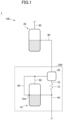
- FIG. 1 is a diagram illustrating an example of the configuration of the compression apparatus 100 according to the embodiment.
- the compression apparatus 100 is provided in a refrigerant circuit 1, which circulates a predetermined refrigerant (to be simply referred to as a "refrigerant” hereinafter) in a heat exchange system such as an air conditioning system or a water heating system, and compresses the refrigerant at a high pressure.
- a refrigerant such as an air conditioning system or a water heating system
- the refrigerant include hydrofluorocarbons (HFCs).
- the compression apparatus 100 includes, compressors 10 and 20, an oil separator 30, an intake passage 40, a discharge passage 50, an oil discharge passage 60, an oil return passage 70, an intake passage 80, and a discharge passage 90.
- the compressors 10 and 20 are connected in series in the refrigerant circuit 1.
- the compressors 10 and 20 each are, for example, a dome-type scroll compressor.
- An oil discharge outlet 10A is provided at a predetermined height position on the side surface of the housing (casing) of the compressor 10 of the compressors 10 and 20.
- the oil separator 30 is provided on the discharge side of the compressor 10 on the low-stage side in the refrigerant circuit 1.
- the oil separator 30 separates oil from an inflowing refrigerant containing the oil, and outputs the refrigerant from which the oil has been separated.
- the intake passage 40 is formed as, for example, a conduit, and is connected to an intake port of the compressor 10.
- the compressor 10 receives the refrigerant of the refrigerant circuit 1 through the intake passage 40.
- the discharge passage 50 is formed as, for example, a conduit, and connects a discharge port of the compressor 10 to an inlet of the oil separator 30.
- the compressor 10 discharges the compressed refrigerant to the discharge passage 50, and the oil separator 30 separates the oil contained in the refrigerant discharged from the compressor 10.
- the oil discharge passage 60 is formed as, for example, a conduit, and connects the oil discharge outlet 10A of the compressor 10 to the discharge passage 50.
- the cross-sectional area (inside diameter), the length, the shape, the merging point with the discharge passage 50, and the like of the oil discharge passage 60 are configured such that, for example, when the oil level inside the compressor 10 reaches the oil discharge outlet 10A, oil accumulated further is discharged outside. This configuration allows the excess oil that accumulates to a height higher than or equal to the height of the oil discharge outlet 10A to be discharged from the compressor 10 to the discharge passage 50 through the oil discharge outlet 10A and the oil discharge passage 60. Hence, the oil in the compressor 10 that is discharged to the discharge passage 50 is introduced to the oil separator 30 through the discharge passage 50.
- one end of the oil discharge passage 60 may be directly connected to the inlet of the oil separator 30 instead of being connected to the discharge passage 50.
- the oil return passage 70 is formed as, for example, a conduit, and connects the oil discharge outlet of the oil separator 30 to the intake passage 40.
- the oil return passage 70 includes a capillary tube 72.
- the intake passage 80 is formed as, for example, a conduit, and connects the outlet of the oil separator 30 with the inlet of the compressor 20.
- the compressor 10 receives the refrigerant, which is output from the oil separator 30 and has been separated from the oil, through the intake passage 80.
- the discharge passage 90 is formed as, for example, a conduit, and is connected to the discharge outlet of the compressor 20.
- the compressor 20 discharges the compressed refrigerant to the discharge passage 90.
- the components including the compressor 10, the oil separator 30, the intake passage 40, the discharge passage 50, the oil discharge passage 60, the oil return passage 70, and the like may also be formed integrally as one compressor unit 200.
- an accumulator that separates the liquid refrigerant may be provided upstream relative to the merging point with the oil return passage 70 in the intake passage 40.
- An accumulator may also be provided in a similar manner in the intake passage 80.
- compression apparatuses 100c and 100cc according to comparative examples (the first comparative example and the second comparative example) will be described with reference to FIGS. 2 to 11 .
- the compression apparatus 100c and the compression apparatus 100cc according to the first comparative example and the second comparative example, respectively, will be described below by using the same reference numerals to denote the same components as the compression apparatus 100 according to the embodiment.
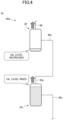
- FIG. 2 is a diagram illustrating an example of the operation of the compression apparatus 100c according to the first comparative example.
- FIGS. 3 and 4 are diagrams illustrating other examples of the operation of the compression apparatus 100c according to the first comparative example.
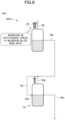
- FIGS. 5 and 6 are diagrams illustrating further examples of the operation of the compression apparatus 100c according to the first comparative example.
- Each dotted arrow in the drawings represents the flow of the oil, and the thickness of each arrow represents the flow rate of the oil.
- the compression apparatus 100c according to the first comparative example is provided in a refrigerant circuit 1c and includes a compressor 10c, the compressor 20, an intake passage 40c, a discharge passage 50c, an intake passage 80c, and the discharge passage 90.
- the compression apparatus 100c according to the first comparative example differs from the compression apparatus 100 according to the embodiment in that the compressor 10c does not include the oil discharge outlet 10A, the oil discharge passage 60 is not provided, and the discharge passage 50c does not include the merging point with the oil discharge passage 60.
- the compression apparatus 100c according to the first comparative example differs from the compression apparatus 100 according to the embodiment in that the oil separator 30 and the oil return passage 70 are absent, the discharge passage 50c is directly connected to the intake passage 80c, and the intake passage 40c does not include the merging point with the oil return passage 70.
- a description will be given hereinafter based on the premise that the characteristics of a rise in oil with respect to the operating state such as the rotational speed (the characteristics of the flow rate of oil discharged together with the refrigerant) are substantially the same between the compressor 10c and 20.
- the flow rates of oil discharged from the compressors 10c and 20 are substantially the same.
- the compressors 10c and 20 include substantially the same amount of oil.
- the oil rise rate of the compressor 20 increases in accordance with the increase in the rotational speed of the compressor 20.
- the flow rate of oil that is circulated in the refrigerant circuit 1c and is received by the compressor 10c increases.
- the oil rise rate of the compressor 10c is maintained, thus causing the flow rate of the oil received by the compressor 20 to be maintained.
- the oil level of the compressor 10c rises in accordance with the increase in the amount of oil contained in the compressor 10c, and the oil level of the compressor 20 falls in accordance with the decrease in the amount of oil contained in the compressor 20.
- the oil rise rate of the compressor 20 decreases in accordance with the reduction in the rotational speed of the compressor 20, thus reducing the flow rate of the oil received by the compressor 10c. Meanwhile, the oil rise rate of the compressor 10c is maintained, thus causing the flow rate of oil received by the compressor 20 to be maintained.
- the oil level of the compressor 10c falls due to the decrease in the amount of oil contained in the compressor 10c
- the oil level of the compressor 20 rises due to the increase in the amount of oil contained in the compressor 20.
- the respective amounts of oil contained in the compressors 10c and 20 may not be equalized because neither of the compressors 10c and 20 includes a discharge outlet capable of discharging excess oil contained therein or is provided with an oil discharge passage or the like.
- FIG. 7 is a diagram illustrating an example of the operation of the compression apparatus 100cc according to the second comparative example.
- FIGS. 8 and 9 are diagrams illustrating other examples of the operation of the compression apparatus 100cc according to the second comparative example.
- FIGS. 10 and 11 are diagrams illustrating further examples of the operation of the compression apparatus 100cc according to the second comparative example.
- Each dotted arrow in the drawings represents the flow of the oil, and the thickness of each arrow represents the flow rate of the oil.
- the compression apparatus 100cc according to the second comparative example is provided in a refrigerant circuit 1cc.
- the compression apparatus 100cc includes the compressors 10 and 20, the intake passage 40c, the discharge passage 50c, the oil discharge passage 60, the intake passage 80c, and the discharge passage 90.
- the compression apparatus 100cc according to the second comparative example differs from the compression apparatus 100 according to the embodiment in that the oil separator 30 and the oil return passage 70 are absent, the intake passage 40c does not include the merging point with the oil return passage 70, and the discharge passage 50c is directly connected to the intake passage 80c.
- a description will be given hereinafter based on the premise that the characteristics of the rise in oil with respect to the operating state such as the rotational speed are substantially the same between the compressor 10 and 20.
- the respective flow rates (oil rise rates) of the oil discharged from the compressors 10 and 20 are substantially the same.
- the compressors 10 and 20 contain substantially the same amount of oil.
- the oil rise rate of the compressor 20 increases in accordance with the increase in the rotational speed of the compressor 20.
- the flow rate of the oil circulated in the refrigerant circuit 1cc and received by the compressor 10 increases.
- the oil rise rate of the compressor 10 is maintained, but the flow rate of the oil received by the compressor 10 increases.
- the excess oil is discharged to the discharge passage 50c through the oil discharge outlet 10A and the oil discharge passage 60 in accordance with the rise of the oil level in the compressor 10. Therefore, as illustrated in FIG. 9 , the amount of oil contained in the compressor 20 remains substantially constant.
- the flow rate of oil received by the compressor 20 increases through the discharge passage 50c and the intake passage 80c.
- the flow rate of oil received by the compressor 20 increases in accordance with the increase in the oil rise rate of the compressor 20, thus causing the amount of oil contained in the compressor 20 to remain substantially constant. Therefore, the compressors 10 and 20 contain substantially the same amount of oil.
- the oil rise rate of the compressor 20 decreases along with the decrease in the rotational speed of the compressor 20.
- the flow rate of oil received by the compressor 10 decreases.
- the oil rise rate of the compressor 10 is maintained, thus causing the flow rate of oil received by the compressor 20 to be maintained.
- FIG. 11 as the oil level of the compressor 10 falls due to the decrease in the amount of oil contained in the compressor 10, the oil level of the compressor 20 rises due to the increase in the amount of oil contained in the compressor 20.
- the compression apparatus 100cc according to the second comparative example can appropriately manage a situation where the amount of oil contained in the compressor 10 increases.
- the compressor 20 does not include the oil discharge outlet and is not provided with the oil discharge passage, the compression apparatus 100cc according to the second comparative example cannot manage a situation where the amount of oil contained in the compressor 20 increases, and may not be able to equalize the respective amounts of oil contained in the compressors 10 and the compressor 20.
- FIGS. 12 and 13 are diagrams illustrating examples of the operation of the compression apparatus 100 according to the embodiment.
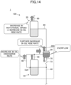
- FIG. 14 is a diagram illustrating another example of the operation of the compression apparatus 100 according to the embodiment.
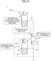
- FIG. 15 is a diagram illustrating yet another example of the operation of the compression apparatus 100 according to the embodiment.
- Each dotted arrow in the drawings represents the flow of the oil, and the thickness of each arrow represents the flow rate of the oil.
- the oil separator 30 is configured such that, in a state where there is no accumulation of oil in the oil separator 30, the flow rate (oil rise rate) of the oil contained in the refrigerant to be discharged to the intake passage 80 becomes lower than the oil rise rate of the compressor 20.
- the flow rate of oil received from the intake passage 80 decreases relative to the flow rate (oil rise rate) of oil discharged to the discharge passage 90.
- the oil separated by the oil separator 30 is returned to the intake passage 40 of the compressor 10 via the oil return passage 70.
- the oil contained in the compressor 10 is discharged to the discharge passage 50 through the compressor 10A and the oil discharge passage 60 in accordance with the increase in the amount of oil contained in the compressor 10.
- the flow rate of oil received from the intake passage 40 is in balance with the total of the flow rate of oil directly discharged to the discharge passage 50 and the flow rate of oil discharged to the oil discharge passage 60. Therefore, the amount of oil (the oil level) contained in the compressor 10 can remain substantially constant.
- the increase in the flow rate of oil that flows into the oil separator 30 reduces the efficiency (to be referred to as "separation efficiency" hereinafter) at which the oil separator 30 separates the refrigerant from the oil, thus causing the oil to accumulate in the oil separator 30.
- separation efficiency there is an upper limit to the flowrate of oil that can flow to the oil return passage 70, including the action of the capillary tube 72.
- the flow rate (oil rise rate) of the oil that is discharged from the oil separator 30 to the intake passage 80 increases in accordance with the reduction in the separation efficiency of the oil separator 30.
- the flow rate of the oil received from the intake passage 80 is in balance with the flow rate (oil rise rate) of the oil discharged to the discharge passage 90. Therefore, the amount (oil level) of oil contained in the compressor 20 can remain substantially constant.
- the compression apparatus 100 can equalize the respective amounts of oil contained in the compressors 10 and 20 in a state where there is a relative reduction in the separation efficiency of the oil separator 30 and the oil has accumulated in the oil separator 30.
- the oil rise rate of the compressor 20 increases in accordance with the increase in the rotational speed of the compressor 20.
- the flow rate of the oil received by the compressor 10 increases.
- the oil rise rate of the compressor 10 is maintained.
- the flow rate of the oil discharged from the compressor 10 to the discharge passage 50 through the oil discharge outlet 10A and the oil discharge passage 60 increases.
- the flow rate of the oil received from the intake passage 40 is in balance with the total of the flow rate of the oil directly discharged to the discharge passage 50 and the flow rate of oil discharged to the oil discharge passage 60, thus allowing the amount (oil level) of oil contained in the compressor 10 to remain substantially constant.
- the increase in the flow rate of the oil discharged from the compressor 10 to the discharge passage 50 through the oil discharge outlet 10A and the oil discharge passage 60 increases the flow rate of the oil that flows into the oil separator 30 through the discharge passage 50. This further reduces the separation efficiency of the oil separator 30, thus causing the oil to further accumulate in the oil separator 30. As a result, the oil separator 30 overflows, increasing the flow rate of the oil (oil rise rate) discharged from the oil separator 30 to the intake passage 80.
- the flow rate of the oil received from the intake passage 80 is in balance with the flow rate of oil (oil rise rate) discharged to the discharge passage 90, thus allowing the amount (oil level) of oil contained in the compressor 10 to remain substantially constant.
- the respective amounts of oil contained in the compressors 10 and 20 can be equalized by further reducing the separation efficiency of the oil separator 30.
- the oil rise rate of the compressor 20 decreases in accordance with the decrease in the rotational speed of the compressor 20.
- the flow rate of the oil received by the compressor 10 decreases.
- the oil rise rate of the compressor 10 is maintained.
- the flow rate of the oil discharged from the compressor 10 to the discharge passage 50 through the oil discharge outlet 10A and the oil discharge passage 60 decreases and, in some cases, the discharge of the oil stops.
- the flow rate of the oil received from the intake passage 40 is in balance with the total of the flow rate of the oil directly discharged to the discharge passage 50 and the flow rate of the oil discharged to the oil discharge passage 60, thus allowing the amount (oil level) of oil contained in the compressor 10 to be maintained.
- This increases (improves) the separation efficiency of the oil separator 30, thus decreasing the amount of the oil accumulated in the oil separator 30.
- the flow rate (oil rise rate) of the oil discharged from the oil separator 30 to the intake passage 80 is decreased.
- the flow rate of the oil received from the intake passage 80 is in balance with the flow rate (oil rise rate) of the oil discharged to the discharge passage 90, thus allowing the amount (oil level) of the oil contained in the compressor 10 to be maintained.
- the respective amounts of oil contained in the compressors 10 and the 20 can be equalized by increasing (improving) the separation efficiency of the oil separator 30.
- the compression apparatus 100 is able to equalize the respective amounts of oil contained in the compressors 10 and 20 in accordance with the increase and decrease of the oil rise rate of the compressor 10.
- the oil discharge outlet 10A, the oil discharge passage 60, the oil separator 30, and the oil return passage 70 corresponding to the compressor 10 on the low stage side (low pressure side) may be omitted, and an oil discharge outlet may be provided in the compressor 20 on the high stage side (high pressure side) along with an oil discharge passage, an oil separator, and an oil return passage.
- the compression apparatus 100 may also include, for example, three or more compressors that are series connected in the refrigerant circuit 1.
- the compressors of the three or more compressors may include an oil discharge outlet and be provided with an oil discharge passage, an oil separator, and an oil return passage, and the remaining compressors may neither include an oil discharge outlet nor be provided with an oil discharge passage, an oil separator, and an oil return passage.
- only two of the compressors may include an oil discharge outlet and be provided with an oil discharge passage, an oil separator, and an oil return passage.
- the respective amounts of oil contained in all of the three or more compressors, including the remaining compressors without the oil discharge outlet, can be equalized based on the action of the oil discharge passage, the oil separator, the oil return passage, and the like provided in some of the compressors.
- the compression apparatus 100 may include, in addition to two or more compressors that are series connected in the refrigerant circuit 1, another compressor that is parallel-connected with respect to one of the series-connected compressors.
- the one compressor includes an oil discharge outlet and is provided with an oil discharge passage, an oil separator, and an oil return passage
- the other compressors may also include an oil discharge passage, and be provided with an oil separator, and an oil return passage.
- a plurality of compressors are series connected in the refrigerant circuit 1 that circulates a refrigerant.
- An oil separator for example, the oil separator 30
- a discharge passage for example, the discharge passage 50
- one compressor for example, the compressor 10
- An oil discharge outlet is provided in the above-described one compressor.
- An oil discharge passage (for example, the oil discharge passage 60) is provided in the above-described one compressor, and connects the oil discharge outlet of the one compressor with an inlet of the oil separator.
- An oil return passage (for example, the oil return passage 70) is provided in the above-described one compressor, and returns the oil separated by the oil separator to an intake passage (for example, the intake passage 40) of the one compressor.
- the compression apparatus 100 can use the oil separator to separate the oil contained in the refrigerant that is discharged from the one compressor provided with the oil separator, and can return the separated oil to the one compressor through the oil return passage.
- the compression apparatus 100 can suppress the reduction in the amount of oil contained in the one compressor.
- the compression apparatus 100 can cause the oil separator to separate at least a part of the oil to reduce the flow rate of the oil discharged together with the refrigerant, and thus suppress an increase in the flow rate of the oil received by another compressor.
- the compression apparatus 100 can cause the oil contained in the one compressor to be discharged to the inlet of the oil separator through the oil discharge passage.
- the flow rate of the oil received by the one compressor is higher than the flow rate of the oil discharged from the one compressor, it is possible to suppress an increase in the amount of oil contained in the one compressor.
- the compression apparatus 100 can reduce the oil separation efficiency of the oil separator to increase the flow rate of oil that flows downstream from the oil separator. This is because the flow rate of the oil return path can be limited.
- a reduction in the flow rate of the oil received by the other compressor can be suppressed.
- the compression apparatus 100 can equalize the respective amounts of oil contained in the plurality of compressors even in a case where compressors other than the one compressor do not include the oil discharge outlet.
- the other compressor(s) different from the above-described one compressor of the plurality of compressors may not include an oil discharge outlet.
- a general compressor without an oil discharge outlet can be employed as the other compressor(s) different from the one compressor that includes the oil discharge outlet and is provided with the oil discharge passage, the oil separator, and the oil return passage.
- the oil separator may be configured such that the flow rate of the oil discharged when the oil is not accumulated inside is lower than the flow rate of the oil discharged together with the refrigerant from the other compressor different from the one compressor that is provided with the oil separator among the plurality of compressors.
- the compression apparatus 100 is able to balance the flow rate of the oil discharged from the oil separator and received by the other compressor with respect to the flow rate of the oil discharged from the other compressor. As a result, the compression apparatus 100 can maintain substantially the same amount of oil in the one compressor and the other compressor in a state where some oil has been accumulated in the oil separator.
- the compression apparatus 100 can reduce the flow rate of the oil discharged from the oil separator to relatively reduce the flow rate of the oil received by the other compressor so as to match the oil rise rate of the other compressor. This is because the flow rate of oil discharged from the one compressor to the oil separator via the oil discharge passage can be reduced. Further, for example, when the oil rise rate of the other compressor increases relative to the oil rise rate of the one compressor, the compression apparatus 100 can increase the flow rate of the oil discharged from the oil separator to relatively increase the flow rate of the oil received by the other compressor so as to match the oil rise rate of the other compressor.
- the compression apparatus 100 can specifically equalize the respective amounts of oil contained in the plurality of compressors.
- the length, the cross-sectional area (inside diameter), the shape, and the like of the oil discharge passage may be configured such that oil does not accumulate to a height that is higher than or equal to a height at which the oil discharge outlet is provided in the above-described one compressor.
- the compression apparatus 100 is able to specifically cause the one compressor including the oil discharge outlet to discharge excess oil to the oil separator.
- the oil return path may limit the flow rate of oil such that the flow rate is less than the amount of oil that can be separated per unit time by the oil separator.
- the compression apparatus 100 can cause the oil to accumulate in the oil separator when the flow rate of oil that flows into the oil separator is relatively high.
- the separated oil may be returned from the oil separator to the above-described one compressor to increase the flow rate of the oil discharged from the one compressor through the oil discharge outlet and the oil discharge passage.
- the compression apparatus 100 can ensure a relatively high flow rate for the oil that is to flow into the oil separator, thus facilitating the accumulation of oil in the oil separator.
- the amount of oil separated per unit time by the oil separator increases as the flow rate of oil that flows into the oil separator from the above-described one compressor via the discharge passage and the oil discharge passage increases. Subsequently, in the oil separator, the amount of oil separated per unit time increases relative to the flow rate of the oil returned by the oil return passage such that the oil separation efficiency decreases and the flow rate of oil discharged downstream is increased.
- the oil separator can specifically suppress a reduction in the flow rate of the oil received by the other compressor.
- the compression apparatus 100 can suppress a reduction in the amount of oil contained in the other compressor, and can equalize the respective amounts of oil contained in the plurality of compressors.
- the oil when there is no change in the flow rate of oil discharged from the above-described other compressor (see FIG. 13 ), the oil is accumulated in the oil separator such that the flow rate of the oil discharged from the oil separator and received by the other compressor increases relative to a state where the oil is not accumulated in the oil separator.
- the increase in the flow rate of the oil received by the other compressor relative to the state where the oil is not accumulated in the oil separator can cause the flow rate of oil received by the other compressor to be in balance with the flow rate of oil discharged from the other compressor.
- the compression apparatus 100 can specifically cause the amount (oil level) of the oil in the other compressor without the oil discharge outlet to remain constant to equalize the respective amounts of oil contained in the plurality of compressors.
- the flow rate of the oil discharged from the above-described other compressor increases such that the flow rate of the oil that flows into the oil separator from the one compressor through the oil discharge passage increases. Further, the increase in the flow rate of oil that flows into the oil separator causes the oil contained in the oil separator to overflow, thus increasing the flow rate of the oil that is discharged from the oil separator and is received by the other compressor. Subsequently, the increase in the flow rate of oil received by the other compressor can cause the flow rate of oil received by the other compressor to be in balance with the flow rate of oil discharged by the other compressor.
- the compression apparatus 100 can specifically cause the amount (oil level) of the oil in the other compressor without the oil discharge outlet to remain constant to equalize the respective amounts of oil contained in the plurality of compressors.
- the flow rate of the oil discharged from the above-described other compressor decreases such that the flow rate of the oil that flows into the oil separator from the one compressor through the oil discharge passage decreases.
- the decrease in the flow rate of oil that flows into the oil separator decreases the amount of oil separated per unit time by the oil separator, thus increasing the flow rate of the oil returned by the oil return passage relative to the amount of separated oil.
- the increase in flow rate of the oil returned by the oil return passage relative to the amount of oil separated per unit time by the oil separator decreases the oil contained in the oil separator, thus increasing the oil separation efficiency of the oil separator.
- the increase in the oil separation efficiency of the oil separator decreases the flow rate of the oil that is discharged from the oil separator and is received by the other compressor. Subsequently, the decrease in the flow rate of oil received by the other compressor can cause the flow rate of oil received by the other compressor to be in balance with the flow rate of oil discharged by the other compressor.
- the compression apparatus 100 can specifically cause the amount (oil level) of the oil contained in the other compressor without the oil discharge outlet to remain constant to equalize the respective amounts of oil contained in the plurality of compressors.
Landscapes
- Engineering & Computer Science (AREA)
- Mechanical Engineering (AREA)
- General Engineering & Computer Science (AREA)
- Physics & Mathematics (AREA)
- Thermal Sciences (AREA)
- Chemical & Material Sciences (AREA)
- Analytical Chemistry (AREA)
- Power Engineering (AREA)
- Compressor (AREA)
- Applications Or Details Of Rotary Compressors (AREA)
- Compressors, Vaccum Pumps And Other Relevant Systems (AREA)
Abstract
Description
- This disclosure relates to a compression apparatus provided in a refrigerant circuit.
- For example, an oil equalization technique related to a plurality of compressors that are connected in series in a refrigerant circuit is known (see Patent Document 1).
- In
Patent Document 1, two compressors are connected in series, and an oil separator is provided on the discharge side of a high-stage compressor. An oil drain passage for discharging oil from the side surface of a low-stage compressor is connected to an intake tube of the high-stage compressor, and an oil drain passage for discharging oil from the side surface of the high-stage compressor is connected to the intake side of the oil separator. The oil separated by the oil separator is returned to the intake side of the low-stage compressor through an oil return passage. As a result, the oil levels of the two series-connected compressors can be kept constant based on the actions of the oil drain passages of the two compressors, the oil separator, and the oil return path. - [Patent Document 1]
Japanese Patent Application Publication No. 2008-261227 - However, in the above-described technique, all of the compressors need to have an oil discharge outlet for discharging excess oil. Hence, the above-described technique cannot be adopted in a case where, for example, a compressor without an oil discharge outlet is included in the plurality of series-connected compressors.
- The present disclosure aims to provide a technique that allows a plurality of series-connected compressors in a refrigerant circuit to have equal amounts of oil in a more versatile manner.
- In one embodiment according to the disclosure, there is provided a compression apparatus that includes a plurality of compressors (10, 20) connected in series in a refrigerant circuit (1) that is configured to circulate a refrigerant; an oil separator (30) provided in a discharge passage of one compressor (10) of the plurality of compressors (10, 20), and configured to separate oil from the refrigerant discharged from the one compressor (10) and to cause the refrigerant separated from the oil to flow downstream; an oil return passage (70) provided with the one compressor (10) and configured to return the oil separated by the oil separator (30) to an intake passage (40) of the one compressor (10); an oil discharge outlet (10A) provided in the one compressor (10); and an oil discharge passage (60) configured to connect the oil discharge outlet (10A) to an inlet of the oil separator (30).
- According to the embodiment, the compression apparatus can cause the oil separator (30) to separate the oil contained in the refrigerant that is discharged from the one compressor (10) provided with the oil separator (30) and to return the oil to the one compressor (10) through the oil return passage (70). Hence, for example, in an operating state where the flow rate of oil discharged from the one compressor (10) is higher than the flow rate of oil received by the one compressor (10), the compression apparatus can suppress a reduction in the amount of oil contained in the one compressor (10). The compression apparatus can also suppress an increase in the flow rate of oil received by another compressor (20) by causing the oil separator (30) to separate at least some of the oil to reduce the flow rate of oil discharged together with the refrigerant. Hence, for example, in an operating state where the flow rate of oil discharged from the one compressor (10) is higher than the flow rate of oil received by the one compressor (10), it is possible to suppress an increase in the amount of oil contained in the other compressor (20). Also, when the oil level in the one compressor (10) is higher than the oil discharge outlet, the compression apparatus can cause the oil contained in the one compressor (10) to be discharged to the inlet of the oil separator (30) through the oil discharge passage (60). Hence, for example, in an operating state where the flow rate of oil received by the one compressor (10) is higher than the flow rate of oil discharged from the one compressor (10), it is possible to suppress an increase in the amount of oil contained in the one compressor (10). Furthermore, when the oil contained in the one compressor (10) is discharged through the oil discharge passage (60) and the flow rate of oil that flows into the oil separator (30) relatively increases, the compression apparatus can reduce the oil separation efficiency of the oil separator (30) to increase the flow rate of oil that flows downstream from the oil separator (30). This is because the flow rate of the oil return path (70) can be limited. Hence, for example, in an operating state where the flow rate of oil received by the one compressor (10) is higher than the flow rate of oil discharged from the one compressor (10), it is possible to suppress a reduction in the flow rate of oil received by the other compressor (20). As a result, it is possible to suppress a reduction in the amount of oil contained in the other compressor (20). Therefore, the compression apparatus can equalize the respective amounts of oil contained in the plurality of compressors even in a case where the compressor (20) other than the one compressor does not include the oil discharge outlet.
- Further, in the above-described embodiment, an oil discharge outlet may not be provided in the other compressor (20) that is different from the one compressor (10) of the plurality of compressors (10, 20) .
- Further, in the above-described embodiment, the oil separator (30) may be configured such that the flow rate of oil discharged downstream from the oil separator (30) when no oil is accumulated in the oil separator (30) is lower than the flow rate of oil discharged from the other compressor (20).
- Further, in the above-described embodiment, the oil discharge passage (60) may be configured such that the oil does not accumulate to a height that is higher than or equal to a height at which the oil discharge outlet (10A) is provided in the one compressor (10).
- Further, in the above-described embodiment, the oil return passage (70) may limit the flow rate of oil such that the flow rate is less than an oil separation amount per unit time of the oil separator (30) .
- Further, in the above-described embodiment, the flow rate of oil discharged from the one compressor (10) through the oil discharge passage (60) increases due to separated oil being returned to the one compressor (10) from the oil separator (30) through the oil return passage (70).
- Further, in the above-described embodiment, in the oil separator (30), an increase in a flow rate of oil that flows in from the one compressor (10) through the discharge passage (50) and the oil discharge passage (60) causes the oil separation amount per unit time to increase and the oil separation amount to increases relative to a flow rate of oil returned by the oil return passage (70) such that the oil is accumulated inside the oil separator. The accumulation of the oil in the oil separator reduces the oil separation efficiency such that the flow rate of oil discharged downstream is increased.
- Further, in the above-described embodiment, when there is no change in the flow rate of oil discharged from the other compressor (20), the accumulation of the oil in the oil separator (30) increases the flow rate of oil that is discharged from the oil separator (30) and is received by the other compressor (20) relative to a state where the oil is not accumulated in the oil separator, and increases the flow rate of oil received by the other compressor (20) relative to the state where the oil is not accumulated in the oil separator, such that the flow rate of oil received by the other compressor (20) is in balance with the oil discharge flow rate of the other compressor (20).
- Further, in the above-described embodiment, when the flow rate of oil discharged from the other compressor (20) increases, the increase in the flow rate of oil that is discharged from the other compressor (20) and is received by the one compressor (10) increases the flow rate of oil that flows into the oil separator (30) from the compressor (10) through the oil discharge passage (60). The increase in the flow rate of oil that flows into the oil separator (30) causes the oil in the oil separator (30) to overflow. The overflow of the oil in the oil separator (30) increases the flow rate of oil that is discharged from the oil separator (30) and is received by the other compressor (20). The increase in the flow rate of oil received by the other compressor (20) causes the flow rate of oil received by the other compressor (20) to be in balance with the flow rate of oil discharged from the other compressor (20).
- Further, in the above-described embodiment, when the flow rate of oil discharged from the other compressor (20) decreases, the decrease in the flow rate of oil that is discharged from the other compressor (20) and is received by the one compressor (10) decreases the flow rate of oil that flows into the oil separator (30) from the one compressor (10) through the oil discharge passage (60). The decrease in the flow rate of oil that flows into the oil separator (30) decreases the oil separation amount of the oil separator (30) such that the flow rate of oil returned by the oil return passage (70) increases relative to the oil separation amount. The increase in the flow rate of oil returned by the oil return passage (70) relative to the oil separation amount decreases the oil in the oil separator (30) such that the oil separation efficiency of the oil separator (30) is increased. The increase in the oil separation efficiency of the oil separator (30) decreases the flow rate of oil that is discharged from the oil separator (30) and is received by the other compressor (20). The decrease in the flow rate of oil received by the other compressor (20) causes the flow rate of oil received by the other compressor (20) to be in balance with the flow rate of oil discharged from the other compressor (20).
- According to the above-described embodiments, the amounts of oil contained in a plurality of series-connected compressors in a refrigerant circuit can be equalized in a more versatile manner.
-
- [
FIG. 1] FIG. 1 is a diagram illustrating an example of the configuration of a compression apparatus; - [
FIG. 2] FIG. 2 is a diagram illustrating an example of the operation of the compression apparatus according to the first comparative example; - [
FIG. 3] FIG. 3 is a diagram illustrating another example of the operation of the compression apparatus according to the first comparative example; - [
FIG. 4] FIG. 4 is a diagram illustrating another example of the operation of the compression apparatus according to the first comparative example; - [
FIG. 5] FIG. 5 is a diagram illustrating yet another example of the operation of the compression apparatus according to the first comparative example; - [
FIG. 6] FIG. 6 is a diagram illustrating yet another example of the operation of the compression apparatus according to the first comparative example; - [
FIG. 7] FIG. 7 is a diagram illustrating an example of the operation of the compression apparatus according to the second comparative example; - [
FIG. 8] FIG. 8 is a diagram illustrating another example of the operation of the compression apparatus according to the second comparative example; - [
FIG. 9] FIG. 9 is a diagram illustrating another example of the operation of the compression apparatus according to the second comparative example; - [
FIG. 10] FIG. 10 is a diagram illustrating yet another example of the operation of the compression apparatus according to the second comparative example; - [
FIG. 11] FIG. 11 is a diagram illustrating yet another example of the operation of the compression apparatus according to the second comparative example; - [
FIG. 12] FIG. 12 is a diagram illustrating an example of the operation of the compression apparatus according to the embodiment; - [
FIG. 13] FIG. 13 is a diagram illustrating an example of the operation of the compression apparatus according to the embodiment; - [
FIG. 14] FIG. 14 is a diagram illustrating another example of the operation of the compression apparatus according to the embodiment; and - [
FIG. 15] FIG. 15 is a diagram illustrating yet another example of the operation of the compression apparatus according to the embodiment. - Hereinafter, an embodiment of this disclosure will be described with reference to the accompanying drawings.
- The configuration of a
compression apparatus 100 will be described first with reference toFIG. 1 . -
FIG. 1 is a diagram illustrating an example of the configuration of thecompression apparatus 100 according to the embodiment. - The
compression apparatus 100 is provided in arefrigerant circuit 1, which circulates a predetermined refrigerant (to be simply referred to as a "refrigerant" hereinafter) in a heat exchange system such as an air conditioning system or a water heating system, and compresses the refrigerant at a high pressure. Examples of the refrigerant include hydrofluorocarbons (HFCs). - The
compression apparatus 100 includes,compressors oil separator 30, anintake passage 40, adischarge passage 50, anoil discharge passage 60, anoil return passage 70, anintake passage 80, and adischarge passage 90. - The
compressors refrigerant circuit 1. Thecompressors - An
oil discharge outlet 10A is provided at a predetermined height position on the side surface of the housing (casing) of thecompressor 10 of thecompressors - The
oil separator 30 is provided on the discharge side of thecompressor 10 on the low-stage side in therefrigerant circuit 1. Theoil separator 30 separates oil from an inflowing refrigerant containing the oil, and outputs the refrigerant from which the oil has been separated. - The
intake passage 40 is formed as, for example, a conduit, and is connected to an intake port of thecompressor 10. Thecompressor 10 receives the refrigerant of therefrigerant circuit 1 through theintake passage 40. - The
discharge passage 50 is formed as, for example, a conduit, and connects a discharge port of thecompressor 10 to an inlet of theoil separator 30. Thecompressor 10 discharges the compressed refrigerant to thedischarge passage 50, and theoil separator 30 separates the oil contained in the refrigerant discharged from thecompressor 10. - The
oil discharge passage 60 is formed as, for example, a conduit, and connects theoil discharge outlet 10A of thecompressor 10 to thedischarge passage 50. The cross-sectional area (inside diameter), the length, the shape, the merging point with thedischarge passage 50, and the like of theoil discharge passage 60 are configured such that, for example, when the oil level inside thecompressor 10 reaches theoil discharge outlet 10A, oil accumulated further is discharged outside. This configuration allows the excess oil that accumulates to a height higher than or equal to the height of theoil discharge outlet 10A to be discharged from thecompressor 10 to thedischarge passage 50 through theoil discharge outlet 10A and theoil discharge passage 60. Hence, the oil in thecompressor 10 that is discharged to thedischarge passage 50 is introduced to theoil separator 30 through thedischarge passage 50. - Note that one end of the
oil discharge passage 60 may be directly connected to the inlet of theoil separator 30 instead of being connected to thedischarge passage 50. - The
oil return passage 70 is formed as, for example, a conduit, and connects the oil discharge outlet of theoil separator 30 to theintake passage 40. Theoil return passage 70 includes acapillary tube 72. As a result, the oil separated by theoil separator 30 is introduced to theintake passage 40 through theoil return passage 70, and is received by thecompressor 10 together with the refrigerant from theintake passage 40. - The
intake passage 80 is formed as, for example, a conduit, and connects the outlet of theoil separator 30 with the inlet of thecompressor 20. Thecompressor 10 receives the refrigerant, which is output from theoil separator 30 and has been separated from the oil, through theintake passage 80. - The
discharge passage 90 is formed as, for example, a conduit, and is connected to the discharge outlet of thecompressor 20. Thecompressor 20 discharges the compressed refrigerant to thedischarge passage 90. - The components including the
compressor 10, theoil separator 30, theintake passage 40, thedischarge passage 50, theoil discharge passage 60, theoil return passage 70, and the like may also be formed integrally as onecompressor unit 200. - Further, an accumulator that separates the liquid refrigerant may be provided upstream relative to the merging point with the
oil return passage 70 in theintake passage 40. An accumulator may also be provided in a similar manner in theintake passage 80. - The operation of
compression apparatuses 100c and 100cc according to comparative examples (the first comparative example and the second comparative example) will be described with reference toFIGS. 2 to 11 . Thecompression apparatus 100c and the compression apparatus 100cc according to the first comparative example and the second comparative example, respectively, will be described below by using the same reference numerals to denote the same components as thecompression apparatus 100 according to the embodiment. -
FIG. 2 is a diagram illustrating an example of the operation of thecompression apparatus 100c according to the first comparative example.FIGS. 3 and4 are diagrams illustrating other examples of the operation of thecompression apparatus 100c according to the first comparative example.FIGS. 5 and6 are diagrams illustrating further examples of the operation of thecompression apparatus 100c according to the first comparative example. Each dotted arrow in the drawings represents the flow of the oil, and the thickness of each arrow represents the flow rate of the oil. - As illustrated in
FIGS. 2 to 6 , thecompression apparatus 100c according to the first comparative example is provided in arefrigerant circuit 1c and includes acompressor 10c, thecompressor 20, anintake passage 40c, adischarge passage 50c, anintake passage 80c, and thedischarge passage 90. Thecompression apparatus 100c according to the first comparative example differs from thecompression apparatus 100 according to the embodiment in that thecompressor 10c does not include theoil discharge outlet 10A, theoil discharge passage 60 is not provided, and thedischarge passage 50c does not include the merging point with theoil discharge passage 60. Furthermore, thecompression apparatus 100c according to the first comparative example differs from thecompression apparatus 100 according to the embodiment in that theoil separator 30 and theoil return passage 70 are absent, thedischarge passage 50c is directly connected to theintake passage 80c, and theintake passage 40c does not include the merging point with theoil return passage 70. A description will be given hereinafter based on the premise that the characteristics of a rise in oil with respect to the operating state such as the rotational speed (the characteristics of the flow rate of oil discharged together with the refrigerant) are substantially the same between thecompressor - Consider a case where, for example, the operating states of the
compressors - In this case, as illustrated in
FIG. 2 , the flow rates of oil discharged from thecompressors compressors - In contrast, consider a case where the rotational speed of the
compressor 20, of thecompressors FIG. 2 . - In this case, as illustrated in
FIG. 3 , the oil rise rate of thecompressor 20 increases in accordance with the increase in the rotational speed of thecompressor 20. As a result, the flow rate of oil that is circulated in therefrigerant circuit 1c and is received by thecompressor 10c increases. Meanwhile, the oil rise rate of thecompressor 10c is maintained, thus causing the flow rate of the oil received by thecompressor 20 to be maintained. Hence, as illustrated inFIG. 4 , the oil level of thecompressor 10c rises in accordance with the increase in the amount of oil contained in thecompressor 10c, and the oil level of thecompressor 20 falls in accordance with the decrease in the amount of oil contained in thecompressor 20. - Furthermore, a similar phenomenon can also occur in a case where, for example, the rotational speed of the
compressor 10c decreases and the oil rise rate of thecompressor 10c accordingly decreases. - A case where the rotational speed of the
compressor 20 of thecompressors FIG. 2 will be further considered. - In this case, as illustrated in
FIG. 5 , the oil rise rate of thecompressor 20 decreases in accordance with the reduction in the rotational speed of thecompressor 20, thus reducing the flow rate of the oil received by thecompressor 10c. Meanwhile, the oil rise rate of thecompressor 10c is maintained, thus causing the flow rate of oil received by thecompressor 20 to be maintained. Hence, as illustrated inFIG. 6 , as the oil level of thecompressor 10c falls due to the decrease in the amount of oil contained in thecompressor 10c, the oil level of thecompressor 20 rises due to the increase in the amount of oil contained in thecompressor 20. - Furthermore, a similar phenomenon can also occur in a case where, for example, the rotational speed of the
compressor 10c increases and the oil rise rate of thecompressor 10c accordingly increases. - In this manner, in the
compression apparatus 100c according to the first comparative example, the respective amounts of oil contained in thecompressors compressors -
FIG. 7 is a diagram illustrating an example of the operation of the compression apparatus 100cc according to the second comparative example.FIGS. 8 and9 are diagrams illustrating other examples of the operation of the compression apparatus 100cc according to the second comparative example.FIGS. 10 and11 are diagrams illustrating further examples of the operation of the compression apparatus 100cc according to the second comparative example. Each dotted arrow in the drawings represents the flow of the oil, and the thickness of each arrow represents the flow rate of the oil. - As illustrated in
FIGS. 7 to 11 , the compression apparatus 100cc according to the second comparative example is provided in a refrigerant circuit 1cc. The compression apparatus 100cc includes thecompressors intake passage 40c, thedischarge passage 50c, theoil discharge passage 60, theintake passage 80c, and thedischarge passage 90. The compression apparatus 100cc according to the second comparative example differs from thecompression apparatus 100 according to the embodiment in that theoil separator 30 and theoil return passage 70 are absent, theintake passage 40c does not include the merging point with theoil return passage 70, and thedischarge passage 50c is directly connected to theintake passage 80c. A description will be given hereinafter based on the premise that the characteristics of the rise in oil with respect to the operating state such as the rotational speed are substantially the same between thecompressor - Consider a case where, for example, the operating states of the
compressors - In this case, as illustrated in
FIG. 7 , the respective flow rates (oil rise rates) of the oil discharged from thecompressors compressors - Further, consider a case where, for example, the rotational speed of the
compressor 20, of thecompressors FIG. 7 . - In this case, as illustrated in
FIG. 8 , the oil rise rate of thecompressor 20 increases in accordance with the increase in the rotational speed of thecompressor 20. As a result, the flow rate of the oil circulated in the refrigerant circuit 1cc and received by thecompressor 10 increases. Further, the oil rise rate of thecompressor 10 is maintained, but the flow rate of the oil received by thecompressor 10 increases. Hence, the excess oil is discharged to thedischarge passage 50c through theoil discharge outlet 10A and theoil discharge passage 60 in accordance with the rise of the oil level in thecompressor 10. Therefore, as illustrated inFIG. 9 , the amount of oil contained in thecompressor 20 remains substantially constant. Further, as the oil that is directly discharged together with the refrigerant from thecompressor 20 merges in thedischarge passage 50c with the oil that flows in through theoil discharge passage 60, the flow rate of oil received by thecompressor 20 increases through thedischarge passage 50c and theintake passage 80c. Hence, as illustrated inFIG. 9 , the flow rate of oil received by thecompressor 20 increases in accordance with the increase in the oil rise rate of thecompressor 20, thus causing the amount of oil contained in thecompressor 20 to remain substantially constant. Therefore, thecompressors - Furthermore, a similar phenomenon can also occur in a case where, for example, the rotational speed of the
compressor 10 decreases and the oil rise rate of thecompressor 10 accordingly decreases. - A case where the rotational speed of the
compressor 20, of thecompressors FIG. 7 will be further considered. - In this case, as illustrated in
FIG. 10 , the oil rise rate of thecompressor 20 decreases along with the decrease in the rotational speed of thecompressor 20. As a result, the flow rate of oil received by thecompressor 10 decreases. Meanwhile, the oil rise rate of thecompressor 10 is maintained, thus causing the flow rate of oil received by thecompressor 20 to be maintained. Hence, as illustrated inFIG. 11 , as the oil level of thecompressor 10 falls due to the decrease in the amount of oil contained in thecompressor 10, the oil level of thecompressor 20 rises due to the increase in the amount of oil contained in thecompressor 20. - Furthermore, a similar phenomenon can also occur in a case where, for example, the rotational speed of the
compressor 10 increases and the oil rise rate of thecompressor 10 decreases. - In this manner, since the
compressor 10 of thecompressors oil discharge outlet 10A and is also provided with theoil discharge passage 60, the compression apparatus 100cc according to the second comparative example can appropriately manage a situation where the amount of oil contained in thecompressor 10 increases. However, since thecompressor 20 does not include the oil discharge outlet and is not provided with the oil discharge passage, the compression apparatus 100cc according to the second comparative example cannot manage a situation where the amount of oil contained in thecompressor 20 increases, and may not be able to equalize the respective amounts of oil contained in thecompressors 10 and thecompressor 20. - The operation of the
compression apparatus 100 according to the embodiment will be described with reference toFIGS. 12 to 15 . -
FIGS. 12 and13 are diagrams illustrating examples of the operation of thecompression apparatus 100 according to the embodiment.FIG. 14 is a diagram illustrating another example of the operation of thecompression apparatus 100 according to the embodiment.FIG. 15 is a diagram illustrating yet another example of the operation of thecompression apparatus 100 according to the embodiment. Each dotted arrow in the drawings represents the flow of the oil, and the thickness of each arrow represents the flow rate of the oil. - Consider a case where, for example, the operating states of the
compressors - In this case, as illustrated in
FIG. 12 , the flow rates of oil discharged from thecompressors - As illustrated in
FIG. 12 , theoil separator 30 is configured such that, in a state where there is no accumulation of oil in theoil separator 30, the flow rate (oil rise rate) of the oil contained in the refrigerant to be discharged to theintake passage 80 becomes lower than the oil rise rate of thecompressor 20. As a result, in thecompressor 20, in a state where there is no accumulation of oil in theoil separator 30, the flow rate of oil received from theintake passage 80 decreases relative to the flow rate (oil rise rate) of oil discharged to thedischarge passage 90. Meanwhile, the oil separated by theoil separator 30 is returned to theintake passage 40 of thecompressor 10 via theoil return passage 70. Thus, as illustrated inFIG. 13 , the oil contained in thecompressor 10 is discharged to thedischarge passage 50 through thecompressor 10A and theoil discharge passage 60 in accordance with the increase in the amount of oil contained in thecompressor 10. Hence, in thecompressor 10, the flow rate of oil received from theintake passage 40 is in balance with the total of the flow rate of oil directly discharged to thedischarge passage 50 and the flow rate of oil discharged to theoil discharge passage 60. Therefore, the amount of oil (the oil level) contained in thecompressor 10 can remain substantially constant. - The oil contained in the
compressor 10, which is discharged to thedischarge passage 50 via theoil discharge passage 60, merges with the oil directly discharged to thedischarge passage 50 from thecompressor 10 and flows into theoil separator 30. Hence, the increase in the flow rate of oil that flows into theoil separator 30 reduces the efficiency (to be referred to as "separation efficiency" hereinafter) at which theoil separator 30 separates the refrigerant from the oil, thus causing the oil to accumulate in theoil separator 30. This is because there is an upper limit to the flowrate of oil that can flow to theoil return passage 70, including the action of thecapillary tube 72. The flow rate (oil rise rate) of the oil that is discharged from theoil separator 30 to theintake passage 80 increases in accordance with the reduction in the separation efficiency of theoil separator 30. Hence, in thecompressor 20, the flow rate of the oil received from theintake passage 80 is in balance with the flow rate (oil rise rate) of the oil discharged to thedischarge passage 90. Therefore, the amount (oil level) of oil contained in thecompressor 20 can remain substantially constant. - In this manner, in a case in which the operating states of the
compressors compression apparatus 100 according to the embodiment can equalize the respective amounts of oil contained in thecompressors oil separator 30 and the oil has accumulated in theoil separator 30. - Further, consider a case where, for example, the rotational speed of the
compressor 20, of thecompressors FIG. 13 . - In this case, as illustrated in
FIG. 14 , the oil rise rate of thecompressor 20 increases in accordance with the increase in the rotational speed of thecompressor 20. As a result, the flow rate of the oil received by thecompressor 10 increases. Meanwhile, the oil rise rate of thecompressor 10 is maintained. As a result, as illustrated inFIG. 14 , the flow rate of the oil discharged from thecompressor 10 to thedischarge passage 50 through theoil discharge outlet 10A and theoil discharge passage 60 increases. Hence, in thecompressor 10, the flow rate of the oil received from theintake passage 40 is in balance with the total of the flow rate of the oil directly discharged to thedischarge passage 50 and the flow rate of oil discharged to theoil discharge passage 60, thus allowing the amount (oil level) of oil contained in thecompressor 10 to remain substantially constant. - Further, the increase in the flow rate of the oil discharged from the
compressor 10 to thedischarge passage 50 through theoil discharge outlet 10A and theoil discharge passage 60 increases the flow rate of the oil that flows into theoil separator 30 through thedischarge passage 50. This further reduces the separation efficiency of theoil separator 30, thus causing the oil to further accumulate in theoil separator 30. As a result, theoil separator 30 overflows, increasing the flow rate of the oil (oil rise rate) discharged from theoil separator 30 to theintake passage 80. Hence, in thecompressor 20, the flow rate of the oil received from theintake passage 80 is in balance with the flow rate of oil (oil rise rate) discharged to thedischarge passage 90, thus allowing the amount (oil level) of oil contained in thecompressor 10 to remain substantially constant. - In this manner, in the
compression apparatus 100 according to the embodiment, in a case where the oil rise rate of thecompressor 20 increases, the respective amounts of oil contained in thecompressors oil separator 30. - Further, a case where the rotational speed of the
compressor 20, of thecompressors FIG. 13 will be considered. - In this case, as illustrated in
FIG. 15 , the oil rise rate of thecompressor 20 decreases in accordance with the decrease in the rotational speed of thecompressor 20. As a result, the flow rate of the oil received by thecompressor 10 decreases. Meanwhile, the oil rise rate of thecompressor 10 is maintained. Thus, as illustrated inFIG. 15 , the flow rate of the oil discharged from thecompressor 10 to thedischarge passage 50 through theoil discharge outlet 10A and theoil discharge passage 60 decreases and, in some cases, the discharge of the oil stops. Hence, in thecompressor 10, the flow rate of the oil received from theintake passage 40 is in balance with the total of the flow rate of the oil directly discharged to thedischarge passage 50 and the flow rate of the oil discharged to theoil discharge passage 60, thus allowing the amount (oil level) of oil contained in thecompressor 10 to be maintained. - Furthermore, the decrease in the flow rate of the oil discharged from the
compressor 10 through theoil discharge outlet 10A and theoil discharge passage 60 decreases the flow rate of oil that flows into theoil separator 30 through thedischarge passage 50. This increases (improves) the separation efficiency of theoil separator 30, thus decreasing the amount of the oil accumulated in theoil separator 30. As a result, the flow rate (oil rise rate) of the oil discharged from theoil separator 30 to theintake passage 80 is decreased. Hence, in thecompressor 20, the flow rate of the oil received from theintake passage 80 is in balance with the flow rate (oil rise rate) of the oil discharged to thedischarge passage 90, thus allowing the amount (oil level) of the oil contained in thecompressor 10 to be maintained. - In this manner, in the
compression apparatus 100 according to the embodiment, in a case where the oil rise rate of thecompressor 20 decreases, the respective amounts of oil contained in thecompressors 10 and the 20 can be equalized by increasing (improving) the separation efficiency of theoil separator 30. - Furthermore, when the oil rise rate of the
compressor 10 increases due to, for example, the rotational speed of thecompressor 10 increasing from the operating state illustrated inFIG. 13 , the amount of oil contained in thecompressor 10 decreases, conversely, and the flow rate of the oil discharged to thedischarge passage 50 through theoil discharge outlet 10A and theoil discharge passage 60 is decreased as a result. In a similar manner, when the oil rise rate of thecompressor 10 decreases due to, for example, the rotational speed of thecompressor 10 decreasing from the operating state illustrated inFIG. 13 , the amount of oil contained in thecompressor 10 increases, conversely, and the flow rate of the oil discharged to thedischarge passage 50 through theoil discharge outlet 10A and theoil discharge passage 60 is increased as a result. Hence, even if the oil rise rate of thecompressor 10 increases or decreases from the operating state illustrated inFIG. 13 , the flow rate of the oil that flows into theoil separator 30 from thedischarge passage 50 hardly changes, thus allowing the state illustrated inFIG. 13 to be maintained. Therefore, thecompression apparatus 100 according to the embodiment is able to equalize the respective amounts of oil contained in thecompressors compressor 10. - Other embodiments will be described next.
- The above-described embodiment may be modified or changed as appropriate.
- For example, the
oil discharge outlet 10A, theoil discharge passage 60, theoil separator 30, and theoil return passage 70 corresponding to thecompressor 10 on the low stage side (low pressure side) may be omitted, and an oil discharge outlet may be provided in thecompressor 20 on the high stage side (high pressure side) along with an oil discharge passage, an oil separator, and an oil return passage. - The
compression apparatus 100 may also include, for example, three or more compressors that are series connected in therefrigerant circuit 1. In such a case, in a similar manner to the above-described embodiment, only some of the compressors of the three or more compressors may include an oil discharge outlet and be provided with an oil discharge passage, an oil separator, and an oil return passage, and the remaining compressors may neither include an oil discharge outlet nor be provided with an oil discharge passage, an oil separator, and an oil return passage. More specifically, in a case where three compressors are series connected, only two of the compressors may include an oil discharge outlet and be provided with an oil discharge passage, an oil separator, and an oil return passage. As a result, the respective amounts of oil contained in all of the three or more compressors, including the remaining compressors without the oil discharge outlet, can be equalized based on the action of the oil discharge passage, the oil separator, the oil return passage, and the like provided in some of the compressors. - Furthermore, for example, the
compression apparatus 100 may include, in addition to two or more compressors that are series connected in therefrigerant circuit 1, another compressor that is parallel-connected with respect to one of the series-connected compressors. In this case, as long as the one compressor includes an oil discharge outlet and is provided with an oil discharge passage, an oil separator, and an oil return passage, the other compressors may also include an oil discharge passage, and be provided with an oil separator, and an oil return passage. - The effects of the
compression apparatus 100 according to the embodiment will be described next. - In the embodiment, a plurality of compressors (for example, the
compressors 10 and 20) are series connected in therefrigerant circuit 1 that circulates a refrigerant. An oil separator (for example, the oil separator 30) is provided in a discharge passage (for example, the discharge passage 50) of one compressor (for example, the compressor 10) of the plurality of compressors, separates oil from the refrigerant discharged from the one compressor, and causes the refrigerant separated from the oil to flow downstream. An oil discharge outlet (for example, theoil discharge outlet 10A) is provided in the above-described one compressor. An oil discharge passage (for example, the oil discharge passage 60) is provided in the above-described one compressor, and connects the oil discharge outlet of the one compressor with an inlet of the oil separator. An oil return passage (for example, the oil return passage 70) is provided in the above-described one compressor, and returns the oil separated by the oil separator to an intake passage (for example, the intake passage 40) of the one compressor. - As a result, the
compression apparatus 100 can use the oil separator to separate the oil contained in the refrigerant that is discharged from the one compressor provided with the oil separator, and can return the separated oil to the one compressor through the oil return passage. Hence, for example, in an operating state where the flow rate of the oil discharged from the one compressor is higher than the flow rate of the oil received by the one compressor, thecompression apparatus 100 can suppress the reduction in the amount of oil contained in the one compressor. Further, thecompression apparatus 100 can cause the oil separator to separate at least a part of the oil to reduce the flow rate of the oil discharged together with the refrigerant, and thus suppress an increase in the flow rate of the oil received by another compressor. Hence, for example, in an operating state where the flow rate of the oil discharged from the one compressor is higher than the flow rate of the oil received by the one compressor, it is possible to suppress an increase in the amount of oil contained in the other compressor. In addition, when the oil level in the one compressor is higher than or equal to the oil discharge outlet, thecompression apparatus 100 can cause the oil contained in the one compressor to be discharged to the inlet of the oil separator through the oil discharge passage. Hence, for example, in an operating state where the flow rate of the oil received by the one compressor is higher than the flow rate of the oil discharged from the one compressor, it is possible to suppress an increase in the amount of oil contained in the one compressor. Furthermore, when the oil contained in the one compressor is discharged through the oil discharge passage and the flow rate of oil that flows into the oil separator relatively increases, thecompression apparatus 100 can reduce the oil separation efficiency of the oil separator to increase the flow rate of oil that flows downstream from the oil separator. This is because the flow rate of the oil return path can be limited. Hence, for example, in an operating state where the flow rate of the oil received by the one compressor is higher than the flow rate of the oil discharged from the one compressor, a reduction in the flow rate of the oil received by the other compressor can be suppressed. As a result, it is possible to suppress a reduction in the amount of oil contained in the other compressor. Therefore, thecompression apparatus 100 can equalize the respective amounts of oil contained in the plurality of compressors even in a case where compressors other than the one compressor do not include the oil discharge outlet. - Further, in the embodiment, the other compressor(s) different from the above-described one compressor of the plurality of compressors may not include an oil discharge outlet.
- As a result, a general compressor without an oil discharge outlet can be employed as the other compressor(s) different from the one compressor that includes the oil discharge outlet and is provided with the oil discharge passage, the oil separator, and the oil return passage.
- Furthermore, in the embodiment, the oil separator may be configured such that the flow rate of the oil discharged when the oil is not accumulated inside is lower than the flow rate of the oil discharged together with the refrigerant from the other compressor different from the one compressor that is provided with the oil separator among the plurality of compressors.
- Thus, in a state where some oil has been accumulated in the oil separator and the efficiency at which the oil is separated from the refrigerant has relatively decreased, the
compression apparatus 100 is able to balance the flow rate of the oil discharged from the oil separator and received by the other compressor with respect to the flow rate of the oil discharged from the other compressor. As a result, thecompression apparatus 100 can maintain substantially the same amount of oil in the one compressor and the other compressor in a state where some oil has been accumulated in the oil separator. Hence, for example, when the oil rise rate of the other compressor decreases relative to the oil rise rate of the one compressor, thecompression apparatus 100 can reduce the flow rate of the oil discharged from the oil separator to relatively reduce the flow rate of the oil received by the other compressor so as to match the oil rise rate of the other compressor. This is because the flow rate of oil discharged from the one compressor to the oil separator via the oil discharge passage can be reduced. Further, for example, when the oil rise rate of the other compressor increases relative to the oil rise rate of the one compressor, thecompression apparatus 100 can increase the flow rate of the oil discharged from the oil separator to relatively increase the flow rate of the oil received by the other compressor so as to match the oil rise rate of the other compressor. This is because the flow rate of oil discharged from the one compressor to the oil separator through the oil discharge passage can be increased, and the oil separation efficiency of the oil separator can be reduced in accordance with the limitation of the flow rate of the oil return passage. Therefore, thecompression apparatus 100 can specifically equalize the respective amounts of oil contained in the plurality of compressors. - In addition, in the embodiment, the length, the cross-sectional area (inside diameter), the shape, and the like of the oil discharge passage may be configured such that oil does not accumulate to a height that is higher than or equal to a height at which the oil discharge outlet is provided in the above-described one compressor.
- As a result, the
compression apparatus 100 is able to specifically cause the one compressor including the oil discharge outlet to discharge excess oil to the oil separator. - In addition, in the embodiment, the oil return path may limit the flow rate of oil such that the flow rate is less than the amount of oil that can be separated per unit time by the oil separator.
- As a result, the
compression apparatus 100 can cause the oil to accumulate in the oil separator when the flow rate of oil that flows into the oil separator is relatively high. - In addition, in the embodiment, the separated oil may be returned from the oil separator to the above-described one compressor to increase the flow rate of the oil discharged from the one compressor through the oil discharge outlet and the oil discharge passage.
- As a result, the
compression apparatus 100 can ensure a relatively high flow rate for the oil that is to flow into the oil separator, thus facilitating the accumulation of oil in the oil separator. - In addition, in the embodiment, the amount of oil separated per unit time by the oil separator increases as the flow rate of oil that flows into the oil separator from the above-described one compressor via the discharge passage and the oil discharge passage increases. Subsequently, in the oil separator, the amount of oil separated per unit time increases relative to the flow rate of the oil returned by the oil return passage such that the oil separation efficiency decreases and the flow rate of oil discharged downstream is increased.
- As a result, in an operating state where the flow rate of the oil received by the above-described one compressor is higher than the flow rate of the oil discharged from the one compressor, the oil separator can specifically suppress a reduction in the flow rate of the oil received by the other compressor. Hence, in an operating state where the flow rate of the oil received by the one compressor is higher than the flow rate of the oil discharged from the one compressor, the
compression apparatus 100 can suppress a reduction in the amount of oil contained in the other compressor, and can equalize the respective amounts of oil contained in the plurality of compressors. - In addition, in the embodiment, when there is no change in the flow rate of oil discharged from the above-described other compressor (see
FIG. 13 ), the oil is accumulated in the oil separator such that the flow rate of the oil discharged from the oil separator and received by the other compressor increases relative to a state where the oil is not accumulated in the oil separator. The increase in the flow rate of the oil received by the other compressor relative to the state where the oil is not accumulated in the oil separator can cause the flow rate of oil received by the other compressor to be in balance with the flow rate of oil discharged from the other compressor. - As a result, when there is no change in the flow rate of oil discharged from the other compressor, the
compression apparatus 100 can specifically cause the amount (oil level) of the oil in the other compressor without the oil discharge outlet to remain constant to equalize the respective amounts of oil contained in the plurality of compressors. - In addition, in the embodiment, when the flow rate of the oil discharged from the above-described other compressor increases, the flow rate of the oil that is discharged from the other compressor and is received by the above-described one compressor increases such that the flow rate of the oil that flows into the oil separator from the one compressor through the oil discharge passage increases. Further, the increase in the flow rate of oil that flows into the oil separator causes the oil contained in the oil separator to overflow, thus increasing the flow rate of the oil that is discharged from the oil separator and is received by the other compressor. Subsequently, the increase in the flow rate of oil received by the other compressor can cause the flow rate of oil received by the other compressor to be in balance with the flow rate of oil discharged by the other compressor.
- As a result, when the flow rate of the oil discharged from the other compressor increases, the
compression apparatus 100 can specifically cause the amount (oil level) of the oil in the other compressor without the oil discharge outlet to remain constant to equalize the respective amounts of oil contained in the plurality of compressors. - In addition, in the embodiment, when the flow rate of the oil discharged from the above-described other compressor decreases, the flow rate of the oil that is discharged from the other compressor and is received by the above-described one compressor decreases such that the flow rate of the oil that flows into the oil separator from the one compressor through the oil discharge passage decreases. Further, the decrease in the flow rate of oil that flows into the oil separator decreases the amount of oil separated per unit time by the oil separator, thus increasing the flow rate of the oil returned by the oil return passage relative to the amount of separated oil. Further, the increase in flow rate of the oil returned by the oil return passage relative to the amount of oil separated per unit time by the oil separator decreases the oil contained in the oil separator, thus increasing the oil separation efficiency of the oil separator. Further, the increase in the oil separation efficiency of the oil separator decreases the flow rate of the oil that is discharged from the oil separator and is received by the other compressor. Subsequently, the decrease in the flow rate of oil received by the other compressor can cause the flow rate of oil received by the other compressor to be in balance with the flow rate of oil discharged by the other compressor.
- As a result, when the flow rate of oil discharged from the other compressor decreases, the
compression apparatus 100 can specifically cause the amount (oil level) of the oil contained in the other compressor without the oil discharge outlet to remain constant to equalize the respective amounts of oil contained in the plurality of compressors. - Although the embodiments have been described above, it can be understood that various changes can be made to the forms and the details without departing from the spirit and the scope of the appended claims.
- Finally, this international application is based on and claims priority to
Japanese Patent Application No. 2020-165578, filed on September 30, 2020 -
- 1 refrigerant circuit
- 10, 20 compressor
- 30 oil separator
- 40 intake passage
- 50 discharge passage
- 60 oil discharge passage
- 70 oil return passage
- 80 intake passage
- 90 discharge passage
- 100 compression apparatus
- 200 compressor unit
Claims (10)
- A compression apparatus comprising:a plurality of compressors (10, 20) connected in series in a refrigerant circuit (1) that is configured to circulate a refrigerant;an oil separator (30) provided in a discharge passage of one compressor (10) of the plurality of compressors (10, 20), and configured to separate oil from the refrigerant discharged from the one compressor (10) and to cause the refrigerant separated from the oil to flow downstream;an oil return passage (70) provided with the one compressor (10) and configured to return the oil separated by the oil separator (30) to an intake passage (40) of the one compressor (10);an oil discharge outlet (10A) provided in the one compressor (10); andan oil discharge passage (60) configured to connect the oil discharge outlet (10A) to an inlet of the oil separator (30).
- The compression apparatus according to claim 1, wherein an oil discharge outlet is not provided in another compressor (20) that is different from the one compressor (10) of the plurality of compressors (10, 20).
- The compression apparatus according to claim 2, wherein the oil separator (30) is configured such that a flow rate of oil discharged downstream from the oil separator (30) when no oil is accumulated in the oil separator (30) is lower than a flow rate of oil discharged from the other compressor (20).
- The compression apparatus according to claim 3, wherein the oil discharge passage (60) is configured such that the oil does not accumulate to a height that is higher than or equal to a height at which the oil discharge outlet (10A) is provided in the one compressor (10).
- The compression apparatus according to claim 3 or 4, wherein the oil return passage (70) is configured to limit a flow rate of oil such that the flow rate is less than an oil separation amount per unit time of the oil separator (30).
- The compression apparatus according to any one of claims 3 to 5, wherein a flow rate of oil discharged from the one compressor (10) through the oil discharge passage (60) increases due to separated oil being returned to the one compressor (10) from the oil separator (30) through the oil return passage (70).
- The compression apparatus according to claim 6, wherein in the oil separator (30),an increase in a flow rate of oil that flows in from the one compressor (10) through a discharge passage (50) and the oil discharge passage (60) causes the oil separation amount per unit time to increase such that the oil separation amount increases relative to a flow rate of oil returned by the oil return passage (70) and the oil is accumulated in the oil separator, andthe accumulation of the oil in the oil separator reduces oil separation efficiency such that the flow rate of oil discharged downstream is increased.
- The compression apparatus according to claim 7, wherein in a case where there is no change in the flow rate of oil discharged from the other compressor (20), the accumulation of the oil in the oil separator (30)increases the flow rate of oil that is discharged from the oil separator (30) and is received by the other compressor (20) relative to a state where the oil is not accumulated in the oil separator, andincreases the flow rate of oil received by the other compressor (20) relative to the state where the oil is not accumulated in the oil separator, such that the flow rate of oil received by the other compressor (20) is in balance with the oil discharge flow rate of the other compressor (20).
- The compression apparatus according to claim 7 or 8, wherein in a case where the flow rate of oil discharged from the other compressor (20) increases,the increase in the flow rate of oil that is discharged from the other compressor (20) and is received by the one compressor (10) increases the flow rate of oil that flows into the oil separator (30) from the one compressor (10) through the oil discharge passage (60),the increase in the flow rate of oil that flows into the oil separator (30) causes the oil in the oil separator (30) to overflow,the overflow of the oil in the oil separator (30) increases the flow rate of oil that is discharged from the oil separator (30) and is received by the other compressor (20), andthe increase in the flow rate of oil received by the other compressor (20) causes the flow rate of oil received by the other compressor (20) to be in balance with the flow rate of oil discharged from the other compressor (20).
- The compression apparatus according to any one of claims 7 to 9, wherein in a case where the flow rate of oil discharged from the other compressor (20) decreases,the decrease in the flow rate of oil that is discharged from the other compressor (20) and is received by the one compressor (10) decreases the flow rate of oil that flows into the oil separator (30) from the one compressor (10) through the oil discharge passage (60),the decrease in the flow rate of oil that flows into the oil separator (30) decreases the oil separation amount of the oil separator (30) such that the flow rate of oil returned by the oil return passage (70) increases relative to the oil separation amount,the increase in the flow rate of oil returned by the oil return passage (70) relative to the oil separation amount decreases the oil in the oil separator (30) such that the oil separation efficiency of the oil separator (30) is increased,the increase in the oil separation efficiency of the oil separator (30) decreases the flow rate of oil that is discharged from the oil separator (30) and is received by the other compressor (20), andthe decrease in the flow rate of oil received by the other compressor (20) causes the flow rate of oil received by the other compressor (20) to be in balance with the flow rate of oil discharged from the other compressor (20).
Applications Claiming Priority (2)
| Application Number | Priority Date | Filing Date | Title |
|---|---|---|---|
| JP2020165578A JP6970363B1 (en) | 2020-09-30 | 2020-09-30 | Compressor |
| PCT/JP2021/029389 WO2022070615A1 (en) | 2020-09-30 | 2021-08-06 | Compression apparatus |
Publications (2)
| Publication Number | Publication Date |
|---|---|
| EP4224014A1 true EP4224014A1 (en) | 2023-08-09 |
| EP4224014A4 EP4224014A4 (en) | 2024-01-24 |
Family
ID=78605710
Family Applications (1)
| Application Number | Title | Priority Date | Filing Date |
|---|---|---|---|
| EP21874918.2A Withdrawn EP4224014A4 (en) | 2020-09-30 | 2021-08-06 | Compression apparatus |
Country Status (5)
| Country | Link |
|---|---|
| US (1) | US11953246B2 (en) |
| EP (1) | EP4224014A4 (en) |
| JP (1) | JP6970363B1 (en) |
| CN (1) | CN116324164A (en) |
| WO (1) | WO2022070615A1 (en) |
Cited By (1)
| Publication number | Priority date | Publication date | Assignee | Title |
|---|---|---|---|---|
| WO2025056623A1 (en) * | 2023-09-13 | 2025-03-20 | TEKO Gesellschaft für Kältetechnik mbH | Coolant circuit and method for operating a cooling system |
Family Cites Families (29)
| Publication number | Priority date | Publication date | Assignee | Title |
|---|---|---|---|---|
| JP4454323B2 (en) * | 2004-01-29 | 2010-04-21 | 三洋電機株式会社 | Refrigeration system |
| KR100592955B1 (en) * | 2005-01-10 | 2006-06-26 | 삼성전자주식회사 | Refrigeration system and its control method |
| KR100700545B1 (en) * | 2005-08-10 | 2007-03-28 | 엘지전자 주식회사 | Apparatus and method for controlling operation of an air conditioner having a plurality of compressors |
| CN100570238C (en) * | 2005-08-26 | 2009-12-16 | 三菱电机株式会社 | Refrigeration and air conditioning unit |
| KR100710368B1 (en) * | 2005-08-31 | 2007-04-23 | 엘지전자 주식회사 | Multi air conditioner |
| JP4967435B2 (en) * | 2006-04-20 | 2012-07-04 | ダイキン工業株式会社 | Refrigeration equipment |
| JP2008261227A (en) * | 2007-04-10 | 2008-10-30 | Daikin Ind Ltd | Compression device |
| CN101779039B (en) * | 2008-05-23 | 2013-01-16 | 松下电器产业株式会社 | Fluid machine and refrigeration cycle device |
| JP2010014349A (en) * | 2008-07-03 | 2010-01-21 | Mayekawa Mfg Co Ltd | Refrigeration cycle and oil-cooled refrigerating machine |
| JP2010139155A (en) * | 2008-12-11 | 2010-06-24 | Fujitsu General Ltd | Refrigeration apparatus |
| US9146046B2 (en) * | 2010-07-28 | 2015-09-29 | Lg Electronics Inc. | Refrigerator and driving method thereof |
| EP2532991B1 (en) * | 2011-06-08 | 2019-10-30 | LG Electronics Inc. | Refrigerating cycle apparatus and method for operating the same |
| JP2013024447A (en) * | 2011-07-19 | 2013-02-04 | Daikin Industries Ltd | Refrigerating device |
| JP2013053757A (en) * | 2011-08-31 | 2013-03-21 | Mitsubishi Heavy Ind Ltd | Refrigerant circuit system |
| JP2014196874A (en) * | 2013-03-29 | 2014-10-16 | 三菱電機株式会社 | Refrigeration cycle device and air conditioner including the same |
| JP6057871B2 (en) * | 2013-09-30 | 2017-01-11 | 三菱重工業株式会社 | Heat pump system and heat pump type water heater |
| CN107270570A (en) * | 2013-09-30 | 2017-10-20 | 三菱重工业株式会社 | Heat pump and heat-pump-type hot-warer supplying machine |
| KR20150050710A (en) * | 2013-10-30 | 2015-05-11 | 엘지전자 주식회사 | Air conditioner and control method of the same |
| KR102198326B1 (en) * | 2013-12-26 | 2021-01-05 | 엘지전자 주식회사 | Air conditioner |
| JP2016166719A (en) * | 2015-03-10 | 2016-09-15 | 株式会社富士通ゼネラル | Air conditioning device |
| CN104848599B (en) * | 2015-05-26 | 2017-06-13 | 珠海格力电器股份有限公司 | Air conditioning system and control method thereof |
| EP3312526B1 (en) * | 2015-06-16 | 2026-03-04 | Guangdong Meizhi Compressor Co., Ltd. | Refrigeration cycle device |
| CN204787380U (en) * | 2015-06-16 | 2015-11-18 | 广东美芝制冷设备有限公司 | Refrigeration cycle device |
| US10337766B2 (en) * | 2015-09-01 | 2019-07-02 | Denso Corporation | Two-stage compression refrigeration cycle |
| JP6615030B2 (en) | 2016-03-28 | 2019-12-04 | 三菱重工サーマルシステムズ株式会社 | Multistage compressor, refrigeration cycle provided with the same, and operation method of multistage compressor |
| CN106440521A (en) * | 2016-12-22 | 2017-02-22 | 广东申菱环境系统股份有限公司 | Safety oil level operation device for compressors connected in parallel |
| KR20180121141A (en) * | 2017-04-28 | 2018-11-07 | 엘지전자 주식회사 | Refrigeration system and Controlling method therefor |
| JP6769472B2 (en) | 2018-11-27 | 2020-10-14 | ダイキン工業株式会社 | Multi-stage compression system |
| JP2020165578A (en) | 2019-03-29 | 2020-10-08 | パナソニックIpマネジメント株式会社 | Heat exchanger shunt |
-
2020
- 2020-09-30 JP JP2020165578A patent/JP6970363B1/en active Active
-
2021
- 2021-08-06 EP EP21874918.2A patent/EP4224014A4/en not_active Withdrawn
- 2021-08-06 US US18/246,747 patent/US11953246B2/en active Active
- 2021-08-06 CN CN202180066359.7A patent/CN116324164A/en active Pending
- 2021-08-06 WO PCT/JP2021/029389 patent/WO2022070615A1/en not_active Ceased
Cited By (1)
| Publication number | Priority date | Publication date | Assignee | Title |
|---|---|---|---|---|
| WO2025056623A1 (en) * | 2023-09-13 | 2025-03-20 | TEKO Gesellschaft für Kältetechnik mbH | Coolant circuit and method for operating a cooling system |
Also Published As
| Publication number | Publication date |
|---|---|
| US20230272951A1 (en) | 2023-08-31 |
| JP6970363B1 (en) | 2021-11-24 |
| EP4224014A4 (en) | 2024-01-24 |
| WO2022070615A1 (en) | 2022-04-07 |
| JP2022057365A (en) | 2022-04-11 |
| CN116324164A (en) | 2023-06-23 |
| US11953246B2 (en) | 2024-04-09 |
Similar Documents
| Publication | Publication Date | Title |
|---|---|---|
| EP1574794B1 (en) | A freezing apparatus | |
| US10760831B2 (en) | Oil distribution in multiple-compressor systems utilizing variable speed | |
| US20130255308A1 (en) | Chiller or heat pump with a falling film evaporator and horizontal oil separator | |
| KR101480546B1 (en) | Air conditioner | |
| KR20090068136A (en) | Air conditioner | |
| JP2003130474A (en) | Refrigeration equipment | |
| US20230384008A1 (en) | Refrigeration system | |
| US11953246B2 (en) | Compression apparatus | |
| WO2004076945A1 (en) | Refrigeration cycle apparatus | |
| CN104848599A (en) | Air conditioning system and control method thereof | |
| US11255587B2 (en) | Oil separator and air conditioner including the same | |
| CN112629076A (en) | Oil return system, air conditioner and control method of oil return system | |
| US10330363B2 (en) | Lubricant separator for a heating, ventilation, and air conditioning system | |
| AU2024201902B2 (en) | Oil management system for multiple compressors | |
| CN105683686B (en) | With the separated refrigerating circuit of oil | |
| CN114526566A (en) | Multi-compressor oil return balance structure, control method thereof and air conditioning system | |
| US7231783B2 (en) | Oil control system for a refrigeration system | |
| JP2005283067A (en) | Air conditioner | |
| KR101854233B1 (en) | Compressor system | |
| KR20140008680A (en) | Air conditioner and control method thereof | |
| JP4176694B2 (en) | Air conditioner | |
| US20250116442A1 (en) | Condenser vessel, system, and method for separating oil from an oil-refrigerant mixture | |
| JP2004205175A (en) | Refrigeration equipment | |
| CN121898029A (en) | Parallel compressor unit | |
| JP2002022294A (en) | Refrigeration device |
Legal Events
| Date | Code | Title | Description |
|---|---|---|---|
| STAA | Information on the status of an ep patent application or granted ep patent |
Free format text: STATUS: THE INTERNATIONAL PUBLICATION HAS BEEN MADE |
|
| PUAI | Public reference made under article 153(3) epc to a published international application that has entered the european phase |
Free format text: ORIGINAL CODE: 0009012 |
|
| STAA | Information on the status of an ep patent application or granted ep patent |
Free format text: STATUS: REQUEST FOR EXAMINATION WAS MADE |
|
| 17P | Request for examination filed |
Effective date: 20230327 |
|
| AK | Designated contracting states |
Kind code of ref document: A1 Designated state(s): AL AT BE BG CH CY CZ DE DK EE ES FI FR GB GR HR HU IE IS IT LI LT LU LV MC MK MT NL NO PL PT RO RS SE SI SK SM TR |
|
| DAV | Request for validation of the european patent (deleted) | ||
| DAX | Request for extension of the european patent (deleted) | ||
| P01 | Opt-out of the competence of the unified patent court (upc) registered |
Effective date: 20231201 |
|
| A4 | Supplementary search report drawn up and despatched |
Effective date: 20240102 |
|
| RIC1 | Information provided on ipc code assigned before grant |
Ipc: F04C 18/02 20060101ALI20231219BHEP Ipc: F04B 39/04 20060101ALI20231219BHEP Ipc: F04C 29/02 20060101ALI20231219BHEP Ipc: F04C 23/00 20060101ALI20231219BHEP Ipc: F04B 41/06 20060101ALI20231219BHEP Ipc: F04B 39/02 20060101AFI20231219BHEP |
|
| STAA | Information on the status of an ep patent application or granted ep patent |
Free format text: STATUS: THE APPLICATION IS DEEMED TO BE WITHDRAWN |
|
| 18D | Application deemed to be withdrawn |
Effective date: 20240720 |