EP4224010B1 - Rotor für eine vertikale windkraftanlage - Google Patents
Rotor für eine vertikale windkraftanlage Download PDFInfo
- Publication number
- EP4224010B1 EP4224010B1 EP23154889.2A EP23154889A EP4224010B1 EP 4224010 B1 EP4224010 B1 EP 4224010B1 EP 23154889 A EP23154889 A EP 23154889A EP 4224010 B1 EP4224010 B1 EP 4224010B1
- Authority
- EP
- European Patent Office
- Prior art keywords
- rotor
- flap
- rotor blade
- blade
- rotor according
- Prior art date
- Legal status (The legal status is an assumption and is not a legal conclusion. Google has not performed a legal analysis and makes no representation as to the accuracy of the status listed.)
- Active
Links
Images

Classifications
-
- F—MECHANICAL ENGINEERING; LIGHTING; HEATING; WEAPONS; BLASTING
- F03—MACHINES OR ENGINES FOR LIQUIDS; WIND, SPRING, OR WEIGHT MOTORS; PRODUCING MECHANICAL POWER OR A REACTIVE PROPULSIVE THRUST, NOT OTHERWISE PROVIDED FOR
- F03D—WIND MOTORS
- F03D3/00—Wind motors with rotation axis substantially perpendicular to the air flow entering the rotor
- F03D3/06—Rotors
-
- F—MECHANICAL ENGINEERING; LIGHTING; HEATING; WEAPONS; BLASTING
- F03—MACHINES OR ENGINES FOR LIQUIDS; WIND, SPRING, OR WEIGHT MOTORS; PRODUCING MECHANICAL POWER OR A REACTIVE PROPULSIVE THRUST, NOT OTHERWISE PROVIDED FOR
- F03D—WIND MOTORS
- F03D3/00—Wind motors with rotation axis substantially perpendicular to the air flow entering the rotor
- F03D3/06—Rotors
- F03D3/062—Rotors characterised by their construction elements
-
- F—MECHANICAL ENGINEERING; LIGHTING; HEATING; WEAPONS; BLASTING
- F03—MACHINES OR ENGINES FOR LIQUIDS; WIND, SPRING, OR WEIGHT MOTORS; PRODUCING MECHANICAL POWER OR A REACTIVE PROPULSIVE THRUST, NOT OTHERWISE PROVIDED FOR
- F03D—WIND MOTORS
- F03D3/00—Wind motors with rotation axis substantially perpendicular to the air flow entering the rotor
- F03D3/005—Wind motors with rotation axis substantially perpendicular to the air flow entering the rotor the axis being vertical
- F03D3/011—Wind motors with rotation axis substantially perpendicular to the air flow entering the rotor the axis being vertical of the lift type, e.g. Darrieus or Musgrove
-
- F—MECHANICAL ENGINEERING; LIGHTING; HEATING; WEAPONS; BLASTING
- F05—INDEXING SCHEMES RELATING TO ENGINES OR PUMPS IN VARIOUS SUBCLASSES OF CLASSES F01-F04
- F05B—INDEXING SCHEME RELATING TO WIND, SPRING, WEIGHT, INERTIA OR LIKE MOTORS, TO MACHINES OR ENGINES FOR LIQUIDS COVERED BY SUBCLASSES F03B, F03D AND F03G
- F05B2240/00—Components
- F05B2240/20—Rotors
- F05B2240/30—Characteristics of rotor blades, i.e. of any element transforming dynamic fluid energy to or from rotational energy and being attached to a rotor
- F05B2240/305—Flaps, slats or spoilers
- F05B2240/3052—Flaps, slats or spoilers adjustable
-
- Y—GENERAL TAGGING OF NEW TECHNOLOGICAL DEVELOPMENTS; GENERAL TAGGING OF CROSS-SECTIONAL TECHNOLOGIES SPANNING OVER SEVERAL SECTIONS OF THE IPC; TECHNICAL SUBJECTS COVERED BY FORMER USPC CROSS-REFERENCE ART COLLECTIONS [XRACs] AND DIGESTS
- Y02—TECHNOLOGIES OR APPLICATIONS FOR MITIGATION OR ADAPTATION AGAINST CLIMATE CHANGE
- Y02E—REDUCTION OF GREENHOUSE GAS [GHG] EMISSIONS, RELATED TO ENERGY GENERATION, TRANSMISSION OR DISTRIBUTION
- Y02E10/00—Energy generation through renewable energy sources
- Y02E10/70—Wind energy
- Y02E10/74—Wind turbines with rotation axis perpendicular to the wind direction
Definitions
- the invention relates to a rotor for a vertical wind turbine.
- Wind turbine rotors are well known and are widely used today as horizontally rotating wind turbines, i.e. with a horizontally arranged axis of rotation. Although horizontal wind turbines have a considerable level of efficiency, they also have known disadvantages, such as wind direction tracking, noise, and severe one-sided wear on the bearings due to their horizontal position and weight.
- Drag rotors are limited in their speed because they can only move as fast as the wind that drives them.
- the rotors are designed as lift rotors and are moved by the principle of aerodynamic lift.
- air is guided above and below the blade.
- the flow is diverted downwards. This creates a negative pressure above the blade (suction side) and an overpressure below the blade (pressure side).
- This pressure difference generates a lift force FA that is perpendicular to the flow, drives the rotor blade and thus sets the rotor in rotation.
- the Darrieus rotor is a version of a lift rotor for vertical wind turbines.
- lift rotors have poor starting properties, which is why they have to be driven briefly to start up. In stronger winds, however, they reach considerable speeds and do not brake themselves like drag rotors. Examples of wind turbines with rotors designed as lift rotors are in CN104314752A and JP2007270746A revealed.
- the present invention is based on the object of providing a wind turbine rotor and a wind turbine which starts independently, delivers power over a wide speed range and overcomes other disadvantages of the prior art.
- a rotor according to the invention is designed for a vertical wind turbine and comprises a rotor hub and at least one rotor blade connected to the rotor hub via struts.
- the rotor blade is essentially designed as a lift rotor.
- the rotor blade preferably has an essentially airfoil-shaped cross section.
- the rotor blade has at least one pivotable flap on a side facing the rotor hub, wherein a folding mechanism is provided which opens the flap at low rotor speeds and closes the flap when the rotor speed increases.
- the folding mechanism can be designed such that the flap folds into the rotor blade when a speed threshold is exceeded.
- the flap When unfolded, the flap forms a resistance rotor that facilitates starting, and thus switches itself off automatically as the speed increases through centrifugal force, thus eliminating the need for complicated control technology.
- the present invention combines the advantages of the resistance rotor, which has good starting behavior, and the lift rotor, which has a high degree of efficiency, and thus enables optimal power conversion over a large speed range.
- the flap can be pivoted from a folded-out position into a folded-in position by an angle range of approximately 30° to 45°.
- the flap in the folded-out position can have an angle of approximately 30° to 45° to the outer surface of the rotor blade, so that the rotor blade acts as a drag rotor when the flap is in the folded-out state.
- the folding mechanism exerts a force on the flap which is directed against the centrifugal force of the flap during operation and folds the flap out in the rest state, wherein the force is less than the centrifugal force acting on the flap at a predetermined speed of the rotor.
- the folding mechanism can comprise one or more magnetic elements, spring elements or the like arranged in the rotor blade and/or in the flap, wherein preferably interacting magnetic elements are provided in the rotor blade and in the flap.
- the rotor blade has a receiving chamber for receiving the flap in the folded state, wherein the magnetic elements are arranged on an inner leg of the flap and on an inner surface of the receiving chamber.
- the rotor blade has a receiving chamber for receiving the flap in the folded-in state, wherein the magnetic elements are arranged on an outer leg of the flap and on an outer surface of the receiving chamber.
- a gap is formed between the rotor blade and the flap when the flap is unfolded.
- a deflection chamber is provided in the rotor blade, which deflects the air flowing in via the flap in the rotor blade and allows it to flow out of the deflection chamber through nozzles in the opposite direction.
- the magnetic elements are electromagnets and/or permanent magnets.
- the magnetic interaction between the magnetic elements in the rotor blade and the flap can be designed to be controllable by an electromagnet in the rotor blade.
- the rotor blade has a central segment and two outer segments, wherein the flap is arranged on the central segment.
- the rotor blades may include winglets.
- the outer segments may have an interlacing and/or a sweep.
- Three, four, five or six substantially identical rotor blades may be provided.
- the rotor blades may have a substantially symmetrical profile shape. However, the rotor blades may also have a substantially asymmetrical profile shape.
- the invention relates in particular to a rotor for a vertical wind turbine comprising at least one rotor blade which is designed as a lift rotor, wherein the rotor blade has at least one flap on the inside, wherein there are magnets in the rotor blade as well as in the flap which open the flap at low speeds due to the magnetic interaction and close it as the speed increases due to the centrifugal force acting on the flap.
- a gap can form between the rotor blade and the flap when the flap is open.
- a deflection chamber is provided which deflects the air masses flowing in from behind in the rotor blade and allows them to flow out through nozzles in the rear area of the rotor blade.
- the magnets can be electromagnets and/or permanent magnets. It can be provided that the magnetic repulsion between the magnets in the rotor blade and the flap can be controlled by an electromagnet in the rotor blade.
- the flap can be attached to only part of the rotor blade as a central segment.
- the rotor blades can be designed with winglets. It can be provided that outer segments are provided on the rotor blade that have an angle of inclination and/or sweep.
- the rotor blades can have a symmetrical or asymmetrical profile shape.
- the invention also relates to a wind power plant with a rotor according to the invention, in particular a vertical wind power plant comprising a rotor according to the invention rotatably arranged on a bearing.
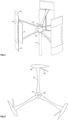
- Fig. 1 shows an isometric view of an embodiment of a vertically mounted rotor of a vertical wind turbine according to the invention.
- the rotor hub 10 is located in the middle.
- the rotor hub 10 is firmly connected to the rotor shaft 20.
- the rotor shaft 20 is rotatably mounted in a vertical bearing 60.
- a generator is driven under the rotor either directly or via a transmission gear.
- the material of the rotor can preferably be light and weather-resistant. Plastics, aluminum or composite materials can be used for this purpose. Low-resistance bearings are used to support the rotor.
- the rotor comprises three vertically extending rotor blades 40, each of which is connected to the centrally arranged rotor hub 10 by means of two struts 30a, 30b.
- the rotor blades 40 are essentially designed as lift rotors, i.e. have a cross-section similar to that of an airfoil profile.
- the rotor blades 40 preferably comprise an inner tube for stiffening.
- a rotor blade 40 comprises an upper outer segment 40a, a lower outer segment 40c and a middle segment 40b.
- the outer segments 40a, 40c function purely as lift rotors.
- the middle segment 40b comprises a flap 50 on its side facing the rotor hub 10, which is open at low rotor speeds, so that the middle segment 40b acts as a drag rotor. As the rotor speed increases, the flap 50 folds in due to the centrifugal force.
- FIG. 2 an embodiment of a rotor according to the invention with three rotor blades 40 is shown.
- the rotor blades 40 are connected to the rotor hub 10 via the struts 30.
- the rotor hub 10 is mounted on the rotor shaft 20.
- Each rotor blade 40 has a flap 50 on its side facing the rotor hub 10, which is open in this illustration.
- the rotor shown is a hybrid of a drag rotor and a lift rotor. It starts up with the flaps 50 extended, i.e. as a drag rotor. As the speed increases, the flaps 50 retract. As soon as the flaps 50 are fully retracted, the rotor works as a lift rotor.
- the ends of the outer segments 40a, 40c are cut straight.
- the ends of the rotor blades 40 can be designed with winglets in order to minimize the formation of edge vortices.
- the angle of attack of the rotor blades 40 can vary or be variable.
- the rotor blades 40 can be interlaced and/or swept. Interlacing is understood to mean the structural twisting of airfoils. Sweep refers to a non-parallel arrangement of the airfoil to the rotor axis.
- the rotor blades 40 taper towards their ends.
- the rotor outer segments 40a, 40c are twisted towards the ends and form a helix shape.
- one rotor outer segment 40a, 40c When twisting, one rotor outer segment 40a, 40c has a positive sweep and the other a negative sweep, but the profile chord of the airfoil is tangential to the rotor circumference.
- the number of rotor blades 40 can vary, but two, three or four rotor blades 40 are preferably provided.
- Fig. 3 shows a rotor according to the invention in a cross section.
- the rotor blades 40 are connected to the rotor hub 10 via the struts 30.
- the rotor hub 10 is mounted on the rotor shaft 20.
- the middle segment 40b of each rotor blade 40 has a flap 50, which are each open in this illustration.
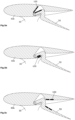
- Fig. 4 shows an enlarged view of the middle segment 40b of a rotor blade 40 of a rotor according to the invention. Shown are the flap 50 in the middle segment 40b and the air gap 70 formed between the middle segment 40b and the flap 50.
- a deflection chamber 80 is provided inside the middle segment 40b, from which a nozzle 90 leads outwards in order to direct an incoming air flow from the flap 50 outwards through the deflection chamber 80.
- the nozzle ends on the side of the middle segment 40b facing away from the rotor hub 10.
- Fig. 5a to Fig. 5c show enlarged sectional views of three embodiments of the middle segment 40b of a rotor blade 40 of a rotor.
- the flap 50 is opened in each case by magnetic interaction using magnetic elements 100.
- opposing magnetic elements 100 are arranged in the middle segment 40b and in the flap 50, which are polarized in such a way that the flap 50 is open when the rotor is at rest.
- the flap 50 comprises an inner leg pivotably mounted in a receiving chamber of the middle segment 40b and an outer leg protruding outward from the receiving chamber.
- the receiving chamber has two inner surfaces arranged at an angle of approximately 30° to limit the position of the inner leg, as well as an outer surface.
- Magnetic elements 100 are arranged on the inner leg and interact with magnetic elements 100 on a first inner surface of the receiving chamber.
- the magnetic elements are polarized such that the inner leg is repelled by the first inner surface of the receiving chamber and rests against the second inner surface of the receiving chamber in the resting state.
- Magnetic elements 100 are arranged on the opposite side of the inner leg and interact with magnetic elements 100 on the second inner surface of the receiving chamber.
- the magnetic elements are polarized in such a way that the inner leg is attracted to the second inner surface of the receiving chamber, so that in the resting state it also rests against the second inner surface of the inner chamber.
- Magnetic elements 100 are arranged on the outer leg and interact with magnetic elements 100 on the outer surface of the receiving chamber.
- the magnetic elements are polarized in such a way that the outer leg is repelled by the outer surface of the receiving chamber, so that the inner leg also rests against the second inner surface of the receiving chamber in the resting state.
Landscapes
- Engineering & Computer Science (AREA)
- Life Sciences & Earth Sciences (AREA)
- Sustainable Development (AREA)
- Sustainable Energy (AREA)
- Chemical & Material Sciences (AREA)
- Combustion & Propulsion (AREA)
- Mechanical Engineering (AREA)
- General Engineering & Computer Science (AREA)
- Wind Motors (AREA)
Description
- Die Erfindung betrifft einen Rotor für eine vertikale Windkraftanlage.
- Windkraftrotoren sind bekannt und heute als horizontal rotierende Windräder, d. h. mit horizontal angeordneter Rotationsachse vielfach im Einsatz. Die horizontalen Windräder weisen zwar einen beachtlichen Wirkungsgrad auf, haben aber auch bekannte Nachteile, wie Windrichtungsnachführung, Geräuschentwicklung, starke einseitige Verschleißerscheinungen der Lager durch ihre horizontale Lage und Gewicht.
- Aus diesem Grunde wurden vertikal rotierende Windräder mit vertikaler Achse konzipiert. Sie machen so gut wie keine Laufgeräusche, haben keine einseitige Lagerbelastung, es ist keine Windrichtungsnachführung notwendig und das Gewicht ist wesentlich geringer als beim horizontalen Windrad.
- Vertikale Windräder umfassen in der Regel Rotoren, die als Widerstandsläufer oder als Auftriebsläufer ausgebildet sind. Ein Widerstandsläufer entnimmt dem Wind Leistung nach dem Widerstandsprinzip und wandelt diese in mechanische Leistung um. Dem Wind wird eine Fläche A entgegengestellt. Diese vermindert die Windströmung, somit entsteht eine Kraft, die die Fläche in Windrichtung schiebt. Widerstandläufer sind in ihren Drehzahlen begrenzt, denn sie können sich nur so schnell bewegen wie der Wind, der sie antreibt.
- Bei modernen Windkraftanlagen sind die Rotoren als Auftriebsläufer ausgebildet und werden durch das Prinzip des aerodynamischen Auftriebs bewegt. Wenn der Wind auf ein Rotorblatt trifft, so wird Luft oberhalb und unterhalb des Blattes entlanggeführt. Die Strömung wird nach unten umgelenkt. Dabei entsteht oberhalb des Blattes ein Unterdruck (Saugseite) und unterhalb des Blattes ein Überdruck (Druckseite). Durch diese Druckdifferenz wird eine Auftriebskraft FA erzeugt, die senkrecht zur Anströmung steht, das Rotorblatt antreibt und somit den Rotor in Drehung versetzt. Der Darrieusrotor ist eine Ausführung eines Auftriebsläufers für vertikale Windkraftanlagen. Derartige Auftriebsläufer haben jedoch schlechte Anlaufeigenschaften, weswegen sie zum Anlaufen kurzzeitig angetrieben werden müssen. Bei stärkerem Wind erreichten sie allerdings beachtliche Drehzahlen und bremsen sich nicht aus wie Widerstandläufer. Beispiele für Windkraftanlagen mit Rotoren, die als Auftriebsläufer ausgebildet sind, sind in
CN104314752A undJP2007270746A - Der vorliegenden Erfindung liegt die Aufgabe zugrunde, einen Windkraftrotor und eine Windkraftanlage zur Verfügung zu stellen, welcher eigenständig anläuft, über einen großen Drehzahlbereich Leistung liefert, sowie weitere Nachteile des Standes der Technik überwindet.
- Erfindungsgemäß wird diese Aufgabe durch einen Rotor mit den Merkmalen des unabhängigen Anspruchs 1 gelöst.
- Ein erfindungsgemäßer Rotor ist für eine vertikale Windkraftanlage ausgebildet und umfasst eine Rotornabe und mindestens einen, mit der Rotornabe über Streben verbundenen Rotorflügel. Der Rotorflügel ist im Wesentlichen als Auftriebsläufer ausgebildet. Vorzugsweise hat der Rotorflügel einen im Wesentlichen tragflügelförmigen Querschnitt.
- Erfindungsgemäß weist der Rotorflügel auf einer zur Rotornabe gerichteten Seite mindestens eine schwenkbare Klappe auf, wobei ein Ausklappmechanismus vorgesehen ist, der bei niedrigen Drehzahlen des Rotors die Klappe öffnet und bei steigender Drehzahl des Rotors die Klappe schließt. Insbesondere kann der Ausklappmechanismus derart ausgebildet sein, dass die Klappe beim Überschreiten eines Drehzahl-Schwellwerts in den Rotorflügel einklappt.
- Die Klappe bildet im ausgeklappten Zustand einen Widerstandsläufer, der als Anlauferleichterung dient, und schaltet sich somit selbständig mit steigender Drehzahl durch Fliehkraft weg, wodurch das Verwenden von komplizierter Regelungstechnik wegfällt.
- Mit dem erfindungsgemäßen Windkraftrotor sowie dem erfindungsgemäßen Rotorflügel ist es möglich, die Windenergie besonders effektiv zu nutzen. Die vorliegende Erfindung vereint die Vorteile des Widerstandsläufer, welcher ein gutes Anlaufverhalten aufweist, und des Auftriebsläufer, der einen hohen Wirkungsgrad hat, und ermöglicht somit eine optimale Leistungsumwandlung über einen große Drehzahlbereich.
- Erfindungsgemäß kann vorgesehen sein, dass die Klappe von einer ausgeklappten Stellung um einen Winkelbereich von etwa 30° bis 45° in eine eingeklappte Stellung schwenkbar ist. Insbesondere kann die Klappe in der ausgeklappten Stellung etwa einen Winkel von 30° bis 45° zur Außenfläche des Rotorflügels aufweisen, sodass der Rotorflügel im ausgeklappten Zustand der Klappe als Widerstandsläufer wirkt.
- Erfindungsgemäß kann vorgesehen sein, dass der Ausklappmechanismus auf die Klappe eine Kraft ausübt, welche entgegen der Fliehkraft der Klappe im Betrieb gerichtet ist und die Klappe im Ruhezustand ausklappt, wobei die Kraft geringer ist als die auf die Klappe bei einer vorgegebenen Drehzahl des Rotors einwirkende Fliehkraft.
- Erfindungsgemäß kann der Ausklappmechanismus ein oder mehrere, im Rotorflügel und/oder in der Klappe angeordnete Magnetelemente, Federelemente oder dergleichen umfassen, wobei vorzugsweise im Rotorflügel und in der Klappe miteinander wechselwirkende Magnetelemente vorgesehen sind.
- Erfindungsgemäß kann vorgesehen sein, dass der Rotorflügel eine Aufnahmekammer zur Aufnahme der Klappe im eingeklappten Zustand aufweist, wobei die Magnetelemente an einem Innenschenkel der Klappe und an einer Innenfläche der Aufnahmekammer angeordnet sind.
- Erfindungsgemäß kann vorgesehen sein, dass der Rotorflügel eine Aufnahmekammer zur Aufnahme der Klappe im eingeklappten Zustand aufweist, wobei die Magnetelemente an einem Außenschenkel der Klappe und an einer Außenfläche der Aufnahmekammer angeordnet sind.
- Erfindungsgemäß kann vorgesehen sein, dass zwischen dem Rotorflügel und der Klappe ein Spalt gebildet ist, wenn die Klappe ausgeklappt ist.
- Erfindungsgemäß ist im Rotorflügel eine Umlenkkammer vorgesehen, welche die über die Klappe einströmende Luft im Rotorflügel umlenkt und durch Düsen in entgegengesetzter Richtung aus der Umlenkkammer ausströmen lässt.
- Erfindungsgemäß kann vorgesehen sein, dass die Magnetelemente Elektromagnete und/oder Dauermagnete sind. Die magnetische Wechselwirkung zwischen den Magnetelementen im Rotorflügel und der Klappe kann durch einen Elektromagneten im Rotorflügel regelbar ausgestaltet sein.
- Erfindungsgemäß kann vorgesehen sein, dass der Rotorflügel ein Mittelsegment und zwei Außensegmente aufweist, wobei die Klappe am Mittelsegment angeordnet ist.
- Die Rotorflügeln können Winglets umfassen. Die Außensegmente können eine Verschränkung und/oder eine Pfeilung aufweisen. Es können drei, vier, fünf oder sechs im Wesentlichen identische Rotorflügel vorgesehen sein. Die Rotorflügel können eine im Wesentlichen symmetrische Profilform haben. Die Rotorflügel können jedoch auch eine im Wesentlichen asymmetrische Profilform haben.
- Die Erfindung betrifft insbesondere einen Rotor für eine vertikale Windkraftanlage umfassend mindestens einen Rotorflügel, der als Auftriebsläufer ausgebildet ist, wobei der Rotorflügel über mindestens eine Klappe auf der Innenseite verfügt, wobei sich im Rotorflügel als auch in der Klappe Magnete befinden, welche bei niedrigen Drehzahlen aufgrund der magnetischen Wechselwirkung die Klappe öffnen und bei sich mit steigender Drehzahl aufgrund der Fliehkraft, welche auf die Klappe wirkt, schließen.
- Zwischen Rotorflügel und Klappe kann ein Spalt entstehen, wenn die Klappe geöffnet ist. Es ist eine Umlenkkammer vorgesehen, welche die von hinten einströmenden Luftmassen im Rotorflügel umgelenkt und durch Düsen im hinteren Bereich des Rotorflügels ausströmen lässt.
- Die Magnete können Elektromagnete und/oder Dauermagnete sein. Es kann vorgesehen sein, dass die magnetische Abstoßung zwischen den Magneten im Rotorflügel und der Klappe durch einen Elektromagneten im Rotorflügel geregelt werden kann.
- Die Klappe kann nur an einem Teil des Rotorflügels als Mittelsegment angebracht sein. Die Rotorflügeln können mit Winglets ausgeführt sein. Es kann vorgesehen sein, dass Außensegmente am Rotorflügel vorgesehen sind, die eine Verschränkung und/oder Pfeilung haben. Die Rotorflügel können eine symmetrische oder asymmetrische Profilform haben.
- Die Erfindung betrifft auch ein Windkraftwerk mit einem erfindungsgemäßen Rotor, insbesondere eine vertikale Windkraftanlage, umfassend einen, auf einer Lagerung drehbar angeordneten erfindungsgemäßen Rotor.
- Weitere Vorteile, Besonderheiten und zweckmäßige Weiterbildungen der Erfindung ergeben sich aus den Unteransprüchen und der nachfolgenden Darstellung bevorzugter Ausführungsbeispiele anhand der Abbildungen.
- Von den Abbildungen zeigt:
-
Fig. 1 eine isometrische Ansicht auf den erfindungsgemäßen Rotor, -
Fig. 2 eine Draufsicht auf den erfindungsgemäßen Rotor -
Fig. 3 eine Aufsicht auf den Querschnitt des erfindungsgemäßen Rotors, -
Fig. 4 eine vergrößerte Aufsicht auf den Querschnitt des erfindungsgemäßen Rotorflügels, -
Fig. 5a bis Fig. 5c vergrößerte Aufsichten auf die Gelenkverbindung eines Rotorflügels. -
Fig. 1 zeigt eine isometrische Ansicht einer Ausführungsform eines erfindungsgemäßen vertikal montierten Rotors einer vertikalen Windkraftanlage. In der Mitte befindet sich die Rotornabe 10. Die Rotornabe 10 ist mit der Rotorwelle 20 fest verbunden. Die Rotorwelle 20 ist in einer vertikalen Lagerung 60 drehbar gelagert. Zum Umwandeln der Rotationsenergie des Rotors in elektrische Energie wird unter dem Rotor ein Generator entweder direkt oder über ein Übersetzungsgetriebe angetrieben. Hierzu können verschiedene Generatortypen eingesetzt werden. Das Material des Rotors kann vorzugsweise leicht und witterungsbeständig sein. Zu diesem Zweck können Kunststoffe, Aluminium oder Verbundwerkstoffe zum Einsatz kommen. Zur Lagerung des Rotors kommen widerstandsarme Lager zum Einsatz. - In dieser Ausführungsform umfasst der Rotor drei vertikal verlaufende Rotorflügel 40, die jeweils mittels zwei Streben 30a, 30b mit der zentral angeordneten Rotornabe 10 verbunden sind. Die Rotorflügel 40 sind im Wesentlichen als Auftriebsläufer ausgebildet, haben also einen Querschnitt ähnlich dem eines Tragflügelprofils. Vorzugsweise umfassen die Rotorflügel 40 ein Innenrohr zur Versteifung.
- Ein Rotorflügel 40 umfasst jeweils ein oberes Außensegment 40a, ein unteres Außensegment 40c und ein Mittelsegment 40b. Die Außensegmente 40a, 40c fungieren als reine Auftriebsläufer. Das Mittelsegment 40b umfasst auf seiner zur Rotornabe 10 gerichteten Seite eine Klappe 50, die bei niedrigen Drehzahlen des Rotors geöffnet ist, sodass das Mittelsegment 40b als Widerstandsläufer wirkt. Bei steigender Drehzahl des Rotors klappt sich die Klappe 50 aufgrund der Fliehkraft ein.
- In
Fig. 2 wird eine Ausführungsform eines erfindungsgemäßen Rotors mit drei Rotorflügeln 40 gezeigt. Die Rotorflügel 40 sind über die Streben 30 mit der Rotornabe 10 verbunden. Die Rotornabe 10 ist auf der Rotorwelle 20 angebracht. Jeder Rotorflügel 40 weist auf seiner zur Rotornabe 10 gerichteten Seite eine Klappe 50 auf, die in dieser Darstellung geöffnet ist. - Der dargestellte Rotor ist ein Hybrid aus Widerstandläufer und Auftriebsläufer. Das Anlaufen erfolgt mit ausgefahrenen Klappen 50, also als Widerstandsläufer. Mit steigender Drehzahl fahren die Klappen 50 ein. Sobald die Klappen 50 vollständig eingefahren sind, arbeitet der Rotor als Auftriebsläufer.
- In dieser Ausführungsform sind die Enden der Außensegmente 40a, 40c gerade abgeschnitten. Die Enden der Rotorflügel 40 können in alternativen Ausführungsformen mit Winglets ausgeführt sein, um die Randwirbelbildung zu minimieren. In einer weiteren Ausführungsform können die Anstellwinkel der Rotorflügel 40 variieren oder variabel sein.
- In weiteren Ausführungsformen können die Rotorflügel 40 verschränkt und/oder gepfeilt werden. Unter Verschränkung versteht man das konstruktive Verwinden von Tragflächen. Als Pfeilung bezeichnet man eine nicht-parallele Anordnung des Tragflügels zur Rotorachse. In einer weiteren Ausführungsform verjüngen sich die Rotorflügel 40 zu ihrem Ende hin. In einer weiteren Ausführungsform sind die Rotoraußensegmente 40a, 40c zu den Enden hin verdrillt und bilden eine Helix-Form.
- Beim Verdrillen weist ein Rotoraußensegment 40a, 40c eine positive und das andere eine negative Pfeilung auf, jedoch steht die Profilsehne des Tragflügels tangential zum Rotorumfang. Die Anzahl der Rotorflügel 40 kann variieren, bevorzugt sind jedoch zwei, drei oder vier Rotorflügel 40 vorgesehen.
-
Fig. 3 zeigt einen erfindungsgemäßen Rotor in einem Querschnitt. Die Rotorflügel 40 sind über die Streben 30 mit der Rotornabe 10 verbunden. Die Rotornabe 10 ist auf der Rotorwelle 20 angebracht. Das Mittelsegment 40b jedes Rotorflügels 40 weist eine Klappe 50 auf, die in dieser Darstellung jeweils geöffnet sind. -
Fig. 4 zeigt eine vergrößerte Ansicht des Mittelsegments 40b eines Rotorflügels 40 eines erfindungsgemäßen Rotors. Gezeigt ist die Klappe 50 im Mittelsegment 40b sowie der zwischen dem Mittelsegment 40b und der Klappe 50 gebildete Luftspalt 70. - Im Inneren des Mittelsegments 40b ist eine Umlenkkammer 80 vorgesehen, aus der eine Düse 90 nach außen führt, um eine eintreffende Luftströmung von der Klappe 50 durch die Umlenkkammer 80 nach außen zu lenken. Die Düse endet auf der Rotornabe 10 abgewandten Seite des Mittelsegments 40b.
-
Fig. 5a bis Fig. 5c zeigen vergrößerte Schnittdarstellungen dreier Ausführungsformen des Mittelsegments 40b eines Rotorflügels 40 eines Rotors. Die Klappe 50 wird dabei jeweils durch magnetische Wechselwirkung unter Verwendung von Magnetelementen 100 geöffnet. Zu diesem Zweck sind im Mittelsegment 40b und in der Klappe 50 gegenüberliegende Magnetelemente 100 abgeordnet, die derart gepolt sind, dass die Klappe 50 im Ruhezustand des Rotors geöffnet ist. Mit steigenden Drehzahlen wird die Wechselwirkung der Magnetelemente 100 durch die Fliehkraft der Klappen 50 überwunden und die Klappen 50 schließen sich. In diesen Ausführungsbeispielen umfasst die Klappe 50 jeweils einen schwenkbar in einer Aufnahmekammer des Mittelsegments 40b gelagerten Innenschenkel und einen aus der Aufnahmekammer nach außen ragenden Außenschenkel. Die Aufnahmekammer weist zwei in einem Winkel von etwa 30° angeordnete Innenflächen zur Positionsbegrenzung des Innenschenkels sowie eine Außenfläche auf. - Gemäß
Fig. 5a sind Magnetelemente 100 am Innenschenkel angeordnet und wirken mit Magnetelementen 100 an einer ersten Innenfläche der Aufnahmekammer zusammen. In dieser Ausführungsform sind die Magnetelemente derart gepolt, dass der Innenschenkel von der ersten Innenfläche der Aufnahmekammer abgestoßen wird und im Ruhezustand an der zweiten Innenfläche der Aufnahmekammer anliegt. - Gemäß
Fig. 5b sind Magnetelemente 100 auf der gegenüberliegenden Seite des Innenschenkels angeordnet und wirken mit Magnetelementen 100 an der zweiten Innenfläche der Aufnahmekammer zusammen. In dieser Ausführungsform sind die Magnetelemente derart gepolt, dass der Innenschenkel von der zweiten Innenfläche der Aufnahmekammer angezogen wird, sodass er im Ruhezustand ebenfalls an der zweiten Innenfläche der Innenkammer anliegt. - Gemäß
Fig. 5c sind Magnetelemente 100 am Außenschenkel angeordnet und wirken mit Magnetelementen 100 an der Außenfläche der Aufnahmekammer zusammen. In dieser Ausführungsform sind die Magnetelemente derart gepolt, dass der Außenschenkel von der Außenfläche der Aufnahmekammer abgestoßen wird, sodass der Innenschenkel im Ruhezustand ebenfalls an der zweiten Innenfläche der Aufnahmekammer anliegt. - Selbstverständlich können auch andere magnetische Anordnungen im Rahmen der vorliegenden Erfindung vorgesehen sein, um zu gewährleisten, dass die Klappe 50 im Ruhezustand des Rotors in einem aus dem Rotorflügel 40 ausgeklappten Zustand verbleibt. Neben magnetischen Mitteln können zu diesem Zweck auch mechanische Mittel, beispielsweise Klammern oder Feder, oder elektrische Mittel, beispielsweise Elektromagnete, erfindungsgemäß vorgesehen sein.
- Die Erfindung beschränkt sich nicht auf die dargestellten Ausführungsbeispiele, sondern umfasst auch alternative Rotoren und Windkraftanlagen im Rahmen der nachfolgenden Patentansprüche.
-
- 10
- Rotornabe
- 20
- Rotorwelle
- 30, 30a, 30b
- Strebe
- 40
- Rotorflügel
- 40a
- oberes Außensegment
- 40b
- Mittelsegment
- 40c
- unteres Außensegment
- 50
- Klappe
- 60
- Lagerung
- 70
- Luftspalt
- 80
- Umlenkkammer
- 90
- Düse
- 100
- Magnetelement
Claims (14)
- Rotor für eine vertikale Windkraftanlage, umfassend mindestens einen Rotorflügel (40), der im Wesentlichen als Auftriebsläufer ausgebildet ist,wobei der Rotorflügel (40) über mindestens eine Klappe (50) auf der Innenseite verfügt, wobei ein Ausklappmechanismus, vorzugsweise in Form von Magneten (100), insbesondere Elektromagnete und/oder Dauermagnete, im Rotorflügel (40) und in der Klappe (50), vorgesehen ist, wodurch bei niedrigen Drehzahlen die Klappe (50) geöffnet und bei steigender Drehzahl aufgrund der Fliehkraft, welche auf die Klappe (50) wirkt, die Klappe (50) geschlossen wird,dadurch gekennzeichnet, dassim Rotorflügel (40) eine Umlenkkammer (80) vorgesehen ist, welche die von hinten einströmenden Luftmassen im Rotorflügel (40) umlenkt und durch Düsen (90) im hinteren Bereich des Rotorflügels (40) ausströmen lässt.
- Rotor nach Anspruch 1, dadurch gekennzeichnet, dass zwischen Rotorflügel (40) und Klappe (50) ein Spalt (70) entsteht, wenn die Klappe (50) geöffnet ist.
- Rotor nach einem der Ansprüche 1 bis 2, dadurch gekennzeichnet, dass die magnetische Abstoßung zwischen den Magneten (100) im Rotorflügel (40) und der Klappe (50) durch einen Elektromagneten im Rotorflügel (40) geregelt werden kann.
- Rotor nach einem der Ansprüche 1 bis 3, dadurch gekennzeichnet, dass die Klappe (50) nur an einem Teil des Rotorflügels (40) als Mittelsegment (40b) angebracht ist.
- Rotor nach einem der Ansprüche 1 bis 4, dadurch gekennzeichnet, dass die Rotorflügeln (40) mit Winglets ausgeführt werden.
- Rotor nach einem der Ansprüche 1 bis 5, dadurch gekennzeichnet, dass der Rotorflügel (40) ein Mittelsegment (40b) und zwei Außensegmente (40a, 40c) aufweist, wobei die Außensegmente (40a, 40c) eine Verschränkung und/oder eine Pfeilung aufweisen.
- Rotor nach einem der Ansprüche 1 bis 6, dadurch gekennzeichnet, dass der Rotorflügel (40) über Streben (30, 30a, 30b) mit einer Rotornabe (10) verbunden ist, wobei die Klappe (50) schwenkbar auf der zur Rotornabe (10) gerichteten Seite angeordnet ist, und wobei der Ausklappmechanismus dazu ausgebildet ist, bei niedrigen Drehzahlen des Rotors die Klappe (50) zu öffnen und bei steigender Drehzahl des Rotors die Klappe (50) zu schließen.
- Rotor nach einem der Ansprüche 1 bis 7, dadurch gekennzeichnet, dass die Klappe (50) von einer ausgeklappten Stellung um einen Winkelbereich von etwa 30° bis 45° in eine eingeklappte Stellung schwenkbar ist.
- Rotor nach einem der Ansprüche 1 bis 8, dadurch gekennzeichnet, dass der Ausklappmechanismus auf die Klappe (50) eine Kraft ausübt, welche entgegen der Fliehkraft der Klappe (50) im Betrieb gerichtet ist und die Klappe (50) im Ruhezustand ausklappt, wobei die Kraft geringer ist als die auf die Klappe (50) bei einer vorgegebenen Drehzahl des Rotors (40) einwirkende Fliehkraft.
- Rotor nach einem der Ansprüche 1 bis 9, dadurch gekennzeichnet, dass der Ausklappmechanismus ein oder mehrere, im Rotorflügel (40) und/oder in der Klappe (50) angeordnete Magnetelemente (100), Federelemente oder dergleichen umfasst, wobei vorzugsweise im Rotorflügel (40) und in der Klappe (50) miteinander wechselwirkende Magnetelemente (100) vorgesehen sind.
- Rotor nach Anspruch 10, dadurch gekennzeichnet, dass der Rotorflügel (40) eine Aufnahmekammer zur Aufnahme der Klappe im eingeklappten Zustand aufweist, wobei die Magnetelemente (100) an einem Innenschenkel der Klappe (50) und an einer Innenfläche der Aufnahmekammer angeordnet sind.
- Rotor nach Anspruch 10, dadurch gekennzeichnet, dass der Rotorflügel (40) eine Aufnahmekammer zur Aufnahme der Klappe im eingeklappten Zustand aufweist, wobei die Magnetelemente (100) an einem Außenschenkel der Klappe (50) und an einer Außenfläche der Aufnahmekammer angeordnet sind.
- Rotor nach einem der Ansprüche 1 bis 12, dadurch gekennzeichnet, dass der Rotorflügel (40) ein Mittelsegment (40b) und zwei Außensegmente (40a, 40c) aufweist, wobei die Klappe (50) am Mittelsegment (40b) angeordnet ist.
- Vertikale Windkraftanlage, umfassend einen, auf einer Lagerung (60) drehbar angeordneten Rotor gemäß einem der Ansprüche 1 bis 13.
Applications Claiming Priority (1)
| Application Number | Priority Date | Filing Date | Title |
|---|---|---|---|
| ATA32/2022A AT525831B1 (de) | 2022-02-04 | 2022-02-04 | Vertikale Windturbine mit integrierten Fliehkraftklappen |
Publications (3)
| Publication Number | Publication Date |
|---|---|
| EP4224010A1 EP4224010A1 (de) | 2023-08-09 |
| EP4224010B1 true EP4224010B1 (de) | 2025-01-29 |
| EP4224010C0 EP4224010C0 (de) | 2025-01-29 |
Family
ID=85174137
Family Applications (1)
| Application Number | Title | Priority Date | Filing Date |
|---|---|---|---|
| EP23154889.2A Active EP4224010B1 (de) | 2022-02-04 | 2023-02-03 | Rotor für eine vertikale windkraftanlage |
Country Status (2)
| Country | Link |
|---|---|
| EP (1) | EP4224010B1 (de) |
| AT (1) | AT525831B1 (de) |
Families Citing this family (1)
| Publication number | Priority date | Publication date | Assignee | Title |
|---|---|---|---|---|
| US11952979B2 (en) * | 2012-08-16 | 2024-04-09 | Zhaotai Wang | Double-layer reverse rotation vertical shaft power machine adopting horizontal combined movable wing |
Family Cites Families (5)
| Publication number | Priority date | Publication date | Assignee | Title |
|---|---|---|---|---|
| JP2007270746A (ja) * | 2006-03-31 | 2007-10-18 | Univ Nihon | 可変翼を有する垂直軸形風水車 |
| JP2011027054A (ja) * | 2009-07-28 | 2011-02-10 | Global Energy Co Ltd | 風車のブレード |
| TWI431194B (zh) * | 2011-09-22 | 2014-03-21 | Hi Vawt Technology Corp | 垂直軸風車利用葉片旋轉離心力控制葉片轉速之方法及裝置 |
| WO2016019467A1 (en) * | 2014-08-05 | 2016-02-11 | Ryan Church | Structure with rigid winglet adapted to traverse a fluid environment |
| CN104314752A (zh) * | 2014-10-09 | 2015-01-28 | 东南大学 | 低速启动升阻互变式叶片垂直轴风机风轮系统 |
-
2022
- 2022-02-04 AT ATA32/2022A patent/AT525831B1/de active
-
2023
- 2023-02-03 EP EP23154889.2A patent/EP4224010B1/de active Active
Also Published As
| Publication number | Publication date |
|---|---|
| AT525831B1 (de) | 2024-02-15 |
| AT525831A1 (de) | 2023-08-15 |
| EP4224010A1 (de) | 2023-08-09 |
| EP4224010C0 (de) | 2025-01-29 |
Similar Documents
| Publication | Publication Date | Title |
|---|---|---|
| DE102011014476B4 (de) | Windturbine | |
| EP2235365B1 (de) | Windkraftanlage | |
| DE19920560A1 (de) | Windkraftanlage mit Vertikalrotor | |
| WO2009036713A1 (de) | Strömungsenergieanlage, insbesondere windkraftanlage | |
| EP2655874B1 (de) | Windkraft-rotor und verfahren zur energieerzeugung damit | |
| EP1923567A2 (de) | Rotorblatt und Windkraftanlage | |
| EP2594784A2 (de) | Vertikalwindturbine und Rotorblatt hierfür | |
| WO1987007328A1 (en) | Wind force plant | |
| DE3315439A1 (de) | Einrichtung zur umformung der natuerlichen stroemungsenergie von wasser bzw. luft | |
| EP4224010A1 (de) | Rotor für eine vertikale windkraftanlage | |
| DE112017004377B4 (de) | Windturbinenanlage | |
| DE892130C (de) | Windmotor | |
| WO2014154199A1 (de) | Rotorblatt einer windenergieanlage mit winglet | |
| EP1789677A1 (de) | Windenergieanlage mit elastisch biegsamen rotorblättern | |
| EP2425124A2 (de) | Unterwasserkraftwerk mit einer bidirektional anströmbaren, gleichsinnig umlaufenden wasserturbine | |
| EP3981981A1 (de) | Rotorblatt für eine windenergieanlage, windenergieanlage und verfahren zur auslegung eines rotorblatts | |
| DE202004017309U1 (de) | Windkraftrotor | |
| EP2920454B1 (de) | Vorrichtung zur nutzbarmachung kinetischer energie eines strömenden mediums | |
| EP3969743A1 (de) | Rotorblatt und windenergieanlage | |
| AT510238B1 (de) | Rotor für ein windrad | |
| DE19807193C1 (de) | Windkraftanlage in Schnelläuferausführung | |
| EP2636892A2 (de) | Windkraftanlage und Verfahren zum Erzeugen von rotatorischer Energie durch Wind | |
| DE8228078U1 (de) | Vertikalachsenrotor | |
| DE202012000907U1 (de) | Strömungskraftanlage | |
| DE202007014366U1 (de) | Blattverstellung für Vertikalwindkraftanlagen |
Legal Events
| Date | Code | Title | Description |
|---|---|---|---|
| PUAI | Public reference made under article 153(3) epc to a published international application that has entered the european phase |
Free format text: ORIGINAL CODE: 0009012 |
|
| STAA | Information on the status of an ep patent application or granted ep patent |
Free format text: STATUS: THE APPLICATION HAS BEEN PUBLISHED |
|
| AK | Designated contracting states |
Kind code of ref document: A1 Designated state(s): AL AT BE BG CH CY CZ DE DK EE ES FI FR GB GR HR HU IE IS IT LI LT LU LV MC ME MK MT NL NO PL PT RO RS SE SI SK SM TR |
|
| STAA | Information on the status of an ep patent application or granted ep patent |
Free format text: STATUS: REQUEST FOR EXAMINATION WAS MADE |
|
| 17P | Request for examination filed |
Effective date: 20240125 |
|
| RBV | Designated contracting states (corrected) |
Designated state(s): AL AT BE BG CH CY CZ DE DK EE ES FI FR GB GR HR HU IE IS IT LI LT LU LV MC ME MK MT NL NO PL PT RO RS SE SI SK SM TR |
|
| REG | Reference to a national code |
Ref country code: DE Free format text: PREVIOUS MAIN CLASS: F03D0003060000 Ref country code: DE Ref legal event code: R079 Ref document number: 502023000493 Country of ref document: DE Free format text: PREVIOUS MAIN CLASS: F03D0003060000 Ipc: F03D0003000000 |
|
| GRAP | Despatch of communication of intention to grant a patent |
Free format text: ORIGINAL CODE: EPIDOSNIGR1 |
|
| STAA | Information on the status of an ep patent application or granted ep patent |
Free format text: STATUS: GRANT OF PATENT IS INTENDED |
|
| RIC1 | Information provided on ipc code assigned before grant |
Ipc: F03D 3/06 20060101ALI20240805BHEP Ipc: F03D 3/00 20060101AFI20240805BHEP |
|
| INTG | Intention to grant announced |
Effective date: 20240822 |
|
| GRAS | Grant fee paid |
Free format text: ORIGINAL CODE: EPIDOSNIGR3 |
|
| GRAA | (expected) grant |
Free format text: ORIGINAL CODE: 0009210 |
|
| STAA | Information on the status of an ep patent application or granted ep patent |
Free format text: STATUS: THE PATENT HAS BEEN GRANTED |
|
| AK | Designated contracting states |
Kind code of ref document: B1 Designated state(s): AL AT BE BG CH CY CZ DE DK EE ES FI FR GB GR HR HU IE IS IT LI LT LU LV MC ME MK MT NL NO PL PT RO RS SE SI SK SM TR |
|
| REG | Reference to a national code |
Ref country code: GB Ref legal event code: FG4D Free format text: NOT ENGLISH |
|
| REG | Reference to a national code |
Ref country code: CH Ref legal event code: EP |
|
| REG | Reference to a national code |
Ref country code: DE Ref legal event code: R096 Ref document number: 502023000493 Country of ref document: DE |
|
| REG | Reference to a national code |
Ref country code: IE Ref legal event code: FG4D Free format text: LANGUAGE OF EP DOCUMENT: GERMAN |
|
| U01 | Request for unitary effect filed |
Effective date: 20250226 |
|
| U07 | Unitary effect registered |
Designated state(s): AT BE BG DE DK EE FI FR IT LT LU LV MT NL PT RO SE SI Effective date: 20250304 |
|
| U20 | Renewal fee for the european patent with unitary effect paid |
Year of fee payment: 3 Effective date: 20250226 |
|
| PG25 | Lapsed in a contracting state [announced via postgrant information from national office to epo] |
Ref country code: RS Free format text: LAPSE BECAUSE OF FAILURE TO SUBMIT A TRANSLATION OF THE DESCRIPTION OR TO PAY THE FEE WITHIN THE PRESCRIBED TIME-LIMIT Effective date: 20250429 |
|
| PG25 | Lapsed in a contracting state [announced via postgrant information from national office to epo] |
Ref country code: PL Free format text: LAPSE BECAUSE OF FAILURE TO SUBMIT A TRANSLATION OF THE DESCRIPTION OR TO PAY THE FEE WITHIN THE PRESCRIBED TIME-LIMIT Effective date: 20250129 |
|
| PG25 | Lapsed in a contracting state [announced via postgrant information from national office to epo] |
Ref country code: ES Free format text: LAPSE BECAUSE OF FAILURE TO SUBMIT A TRANSLATION OF THE DESCRIPTION OR TO PAY THE FEE WITHIN THE PRESCRIBED TIME-LIMIT Effective date: 20250129 |
|
| PG25 | Lapsed in a contracting state [announced via postgrant information from national office to epo] |
Ref country code: IS Free format text: LAPSE BECAUSE OF FAILURE TO SUBMIT A TRANSLATION OF THE DESCRIPTION OR TO PAY THE FEE WITHIN THE PRESCRIBED TIME-LIMIT Effective date: 20250529 Ref country code: NO Free format text: LAPSE BECAUSE OF FAILURE TO SUBMIT A TRANSLATION OF THE DESCRIPTION OR TO PAY THE FEE WITHIN THE PRESCRIBED TIME-LIMIT Effective date: 20250429 |
|
| PG25 | Lapsed in a contracting state [announced via postgrant information from national office to epo] |
Ref country code: HR Free format text: LAPSE BECAUSE OF FAILURE TO SUBMIT A TRANSLATION OF THE DESCRIPTION OR TO PAY THE FEE WITHIN THE PRESCRIBED TIME-LIMIT Effective date: 20250129 |
|
| PG25 | Lapsed in a contracting state [announced via postgrant information from national office to epo] |
Ref country code: GR Free format text: LAPSE BECAUSE OF FAILURE TO SUBMIT A TRANSLATION OF THE DESCRIPTION OR TO PAY THE FEE WITHIN THE PRESCRIBED TIME-LIMIT Effective date: 20250430 |
|
| PG25 | Lapsed in a contracting state [announced via postgrant information from national office to epo] |
Ref country code: SM Free format text: LAPSE BECAUSE OF FAILURE TO SUBMIT A TRANSLATION OF THE DESCRIPTION OR TO PAY THE FEE WITHIN THE PRESCRIBED TIME-LIMIT Effective date: 20250129 |
|
| PG25 | Lapsed in a contracting state [announced via postgrant information from national office to epo] |
Ref country code: MC Free format text: LAPSE BECAUSE OF FAILURE TO SUBMIT A TRANSLATION OF THE DESCRIPTION OR TO PAY THE FEE WITHIN THE PRESCRIBED TIME-LIMIT Effective date: 20250129 |
|
| PG25 | Lapsed in a contracting state [announced via postgrant information from national office to epo] |
Ref country code: CZ Free format text: LAPSE BECAUSE OF FAILURE TO SUBMIT A TRANSLATION OF THE DESCRIPTION OR TO PAY THE FEE WITHIN THE PRESCRIBED TIME-LIMIT Effective date: 20250129 |
|
| PG25 | Lapsed in a contracting state [announced via postgrant information from national office to epo] |
Ref country code: SK Free format text: LAPSE BECAUSE OF FAILURE TO SUBMIT A TRANSLATION OF THE DESCRIPTION OR TO PAY THE FEE WITHIN THE PRESCRIBED TIME-LIMIT Effective date: 20250129 |
|
| PLBE | No opposition filed within time limit |
Free format text: ORIGINAL CODE: 0009261 |
|
| STAA | Information on the status of an ep patent application or granted ep patent |
Free format text: STATUS: NO OPPOSITION FILED WITHIN TIME LIMIT |
|
| REG | Reference to a national code |
Ref country code: CH Ref legal event code: L10 Free format text: ST27 STATUS EVENT CODE: U-0-0-L10-L00 (AS PROVIDED BY THE NATIONAL OFFICE) Effective date: 20251210 |
|
| 26N | No opposition filed |
Effective date: 20251030 |
|
| U20 | Renewal fee for the european patent with unitary effect paid |
Year of fee payment: 4 Effective date: 20251211 |
|
| PG25 | Lapsed in a contracting state [announced via postgrant information from national office to epo] |
Ref country code: IE Free format text: LAPSE BECAUSE OF NON-PAYMENT OF DUE FEES Effective date: 20250203 |
|
| REG | Reference to a national code |
Ref country code: CH Ref legal event code: U11 Free format text: ST27 STATUS EVENT CODE: U-0-0-U10-U11 (AS PROVIDED BY THE NATIONAL OFFICE) Effective date: 20260301 |
|
| PGFP | Annual fee paid to national office [announced via postgrant information from national office to epo] |
Ref country code: CH Payment date: 20260301 Year of fee payment: 4 |