EP4223593B1 - Stereokamerasystem für rückansicht - Google Patents
Stereokamerasystem für rückansicht Download PDFInfo
- Publication number
- EP4223593B1 EP4223593B1 EP22155749.9A EP22155749A EP4223593B1 EP 4223593 B1 EP4223593 B1 EP 4223593B1 EP 22155749 A EP22155749 A EP 22155749A EP 4223593 B1 EP4223593 B1 EP 4223593B1
- Authority
- EP
- European Patent Office
- Prior art keywords
- cameras
- camera system
- camera
- pair
- utility vehicle
- Prior art date
- Legal status (The legal status is an assumption and is not a legal conclusion. Google has not performed a legal analysis and makes no representation as to the accuracy of the status listed.)
- Active
Links
Images
Classifications
-
- G—PHYSICS
- G06—COMPUTING OR CALCULATING; COUNTING
- G06V—IMAGE OR VIDEO RECOGNITION OR UNDERSTANDING
- G06V20/00—Scenes; Scene-specific elements
- G06V20/50—Context or environment of the image
- G06V20/56—Context or environment of the image exterior to a vehicle by using sensors mounted on the vehicle
-
- B—PERFORMING OPERATIONS; TRANSPORTING
- B60—VEHICLES IN GENERAL
- B60R—VEHICLES, VEHICLE FITTINGS, OR VEHICLE PARTS, NOT OTHERWISE PROVIDED FOR
- B60R1/00—Optical viewing arrangements; Real-time viewing arrangements for drivers or passengers using optical image capturing systems, e.g. cameras or video systems specially adapted for use in or on vehicles
- B60R1/20—Real-time viewing arrangements for drivers or passengers using optical image capturing systems, e.g. cameras or video systems specially adapted for use in or on vehicles
- B60R1/31—Real-time viewing arrangements for drivers or passengers using optical image capturing systems, e.g. cameras or video systems specially adapted for use in or on vehicles providing stereoscopic vision
-
- B—PERFORMING OPERATIONS; TRANSPORTING
- B60—VEHICLES IN GENERAL
- B60R—VEHICLES, VEHICLE FITTINGS, OR VEHICLE PARTS, NOT OTHERWISE PROVIDED FOR
- B60R1/00—Optical viewing arrangements; Real-time viewing arrangements for drivers or passengers using optical image capturing systems, e.g. cameras or video systems specially adapted for use in or on vehicles
- B60R1/20—Real-time viewing arrangements for drivers or passengers using optical image capturing systems, e.g. cameras or video systems specially adapted for use in or on vehicles
- B60R1/22—Real-time viewing arrangements for drivers or passengers using optical image capturing systems, e.g. cameras or video systems specially adapted for use in or on vehicles for viewing an area outside the vehicle, e.g. the exterior of the vehicle
- B60R1/23—Real-time viewing arrangements for drivers or passengers using optical image capturing systems, e.g. cameras or video systems specially adapted for use in or on vehicles for viewing an area outside the vehicle, e.g. the exterior of the vehicle with a predetermined field of view
- B60R1/25—Real-time viewing arrangements for drivers or passengers using optical image capturing systems, e.g. cameras or video systems specially adapted for use in or on vehicles for viewing an area outside the vehicle, e.g. the exterior of the vehicle with a predetermined field of view to the sides of the vehicle
-
- B—PERFORMING OPERATIONS; TRANSPORTING
- B60—VEHICLES IN GENERAL
- B60R—VEHICLES, VEHICLE FITTINGS, OR VEHICLE PARTS, NOT OTHERWISE PROVIDED FOR
- B60R11/00—Arrangements for holding or mounting articles, not otherwise provided for
- B60R11/04—Mounting of cameras operative during drive; Arrangement of controls thereof relative to the vehicle
-
- G—PHYSICS
- G06—COMPUTING OR CALCULATING; COUNTING
- G06T—IMAGE DATA PROCESSING OR GENERATION, IN GENERAL
- G06T7/00—Image analysis
- G06T7/20—Analysis of motion
-
- G—PHYSICS
- G06—COMPUTING OR CALCULATING; COUNTING
- G06V—IMAGE OR VIDEO RECOGNITION OR UNDERSTANDING
- G06V10/00—Arrangements for image or video recognition or understanding
- G06V10/70—Arrangements for image or video recognition or understanding using pattern recognition or machine learning
- G06V10/74—Image or video pattern matching; Proximity measures in feature spaces
- G06V10/761—Proximity, similarity or dissimilarity measures
-
- H—ELECTRICITY
- H04—ELECTRIC COMMUNICATION TECHNIQUE
- H04N—PICTORIAL COMMUNICATION, e.g. TELEVISION
- H04N13/00—Stereoscopic video systems; Multi-view video systems; Details thereof
- H04N13/20—Image signal generators
- H04N13/204—Image signal generators using stereoscopic image cameras
-
- B—PERFORMING OPERATIONS; TRANSPORTING
- B60—VEHICLES IN GENERAL
- B60R—VEHICLES, VEHICLE FITTINGS, OR VEHICLE PARTS, NOT OTHERWISE PROVIDED FOR
- B60R2300/00—Details of viewing arrangements using cameras and displays, specially adapted for use in a vehicle
- B60R2300/80—Details of viewing arrangements using cameras and displays, specially adapted for use in a vehicle characterised by the intended use of the viewing arrangement
- B60R2300/8046—Details of viewing arrangements using cameras and displays, specially adapted for use in a vehicle characterised by the intended use of the viewing arrangement for replacing a rear-view mirror system
-
- G—PHYSICS
- G06—COMPUTING OR CALCULATING; COUNTING
- G06T—IMAGE DATA PROCESSING OR GENERATION, IN GENERAL
- G06T2207/00—Indexing scheme for image analysis or image enhancement
- G06T2207/10—Image acquisition modality
- G06T2207/10004—Still image; Photographic image
- G06T2207/10012—Stereo images
-
- G—PHYSICS
- G06—COMPUTING OR CALCULATING; COUNTING
- G06T—IMAGE DATA PROCESSING OR GENERATION, IN GENERAL
- G06T2207/00—Indexing scheme for image analysis or image enhancement
- G06T2207/20—Special algorithmic details
- G06T2207/20084—Artificial neural networks [ANN]
-
- G—PHYSICS
- G06—COMPUTING OR CALCULATING; COUNTING
- G06T—IMAGE DATA PROCESSING OR GENERATION, IN GENERAL
- G06T2207/00—Indexing scheme for image analysis or image enhancement
- G06T2207/20—Special algorithmic details
- G06T2207/20228—Disparity calculation for image-based rendering
-
- G—PHYSICS
- G06—COMPUTING OR CALCULATING; COUNTING
- G06T—IMAGE DATA PROCESSING OR GENERATION, IN GENERAL
- G06T2207/00—Indexing scheme for image analysis or image enhancement
- G06T2207/30—Subject of image; Context of image processing
- G06T2207/30248—Vehicle exterior or interior
- G06T2207/30252—Vehicle exterior; Vicinity of vehicle
-
- G—PHYSICS
- G06—COMPUTING OR CALCULATING; COUNTING
- G06V—IMAGE OR VIDEO RECOGNITION OR UNDERSTANDING
- G06V2201/00—Indexing scheme relating to image or video recognition or understanding
- G06V2201/07—Target detection
Definitions
- the present invention relates generally to the field of camera systems. More specifically, the invention relates to a rear-view stereo camera system providing information of the left and right side areas and a back area behind a utility vehicle.
- Stereo camera systems in automotive applications are already known in order to provide image information of the scene in front of the ego-vehicle.
- the cameras are typically used in a horizontal arrangement, i.e. the cameras are arranged next to each other at a horizontal distance. Therefore, stereo cameras for automobile applications are usually optimized for a wide horizontal baseline.
- the invention refers to a camera system for a utility vehicle.
- the camera system comprises two pairs of cameras.
- a first pair of cameras is arranged at the left side portion of the cabin of the utility vehicle, preferably at the front portion in the transition area between the front window and the left side window.
- a second pair of cameras is arranged at the right side portion of the cabin of the utility vehicle, preferably at the front portion in the transition area between the front window and the right side window.
- the cameras of the first and second pair of cameras are arranged one above the other in a vertical direction.
- the first pair of cameras builds a rear-viewing stereo camera system for providing image information and distance information of an area on the left side of the utility vehicle.
- the second pair of cameras builds a rear-viewing stereo camera system for providing image information and distance information of an area on the right side of the utility vehicle.
- the cameras of the first and second pair of cameras are arranged by means of one or more spacers at the cabin of the utility vehicle.
- the spacers provide a lateral distance of the cameras to the cabin, e.g. a distance of 10cm or more.
- the cameras of each pair of cameras have a vertical distance of at least 0.5m.
- Said camera system is advantageous because it provides image and distance information of objects besides and behind the utility vehicle independent of a potential trailer arranged at the utility vehicle and additionally reduces the occlusion caused by a trailer of the utility vehicle.
- a first camera of the pairs of cameras is arranged as an upper camera in a height area between the top of the cabin and the upper edge of a side window of the cabin.
- the upper camera provides image information from the top or essentially the top of the cabin which is advantageous for observing objects behind the utility vehicle and for obtaining a large distance between the upper and lower camera of the pair of cameras.
- a second camera of the pairs of cameras is arranged as a lower camera in a height area between the upper edge of the side window and the lower edge of the side window.
- the lower camera provides image information in a height which is advantageous for observing pedestrians or cyclists.
- a large distance between the upper and lower camera of the pair of cameras can be obtained.
- a first camera of the pairs of cameras is arranged as an upper camera in a height range between 3.5m and 4m.
- the first cameras can provide an improved overview over the scene next to and behind the utility vehicle.
- a second camera of the pairs of cameras is arranged as a lower camera in a height range between 2m and 3m.
- a sufficient distance to the upper cameras can be provided and the perspective of the second camera is different to the perspective of the first camera which is advantageous for observing the area next to and behind the utility vehicle.
- the cameras comprise a rectangular or essentially rectangular field of view and the cameras are positioned to provide portrait view.
- the height of the field of view is greater than the width of the field of view.
- the cameras are of greyscale type. Thereby it is possible to improve the sensitivity of the camera system and the operability at poor ambient light, e.g. in the evening or during the night because, in contrary to front-viewing cameras, there is no illumination of the area next to and behind the utility vehicle.
- the cameras may be infrared cameras or cameras of greyscale type which have a sensitivity in the infrared wavelength region. Thereby the sensitivity at night can be increased.
- the first pair of cameras is configured to provide image information to a left rear view monitor and the second pair of cameras is configured to provide image information to a right rear view monitor for rear-view mirror replacement.
- the cameras comprise a nonlinear optic with a higher magnification in the center portion of the field of view than in the peripheral area of the field of view.
- the camera system comprises a control unit configured to compensate the magnification difference between the center portion and the peripheral area of the field of view. Thereby it is possible to remove the nonlinearity of the camera optic and provide image information at a display or monitor with equal magnification in order to ease perceiving of image information for a human driver of the utility vehicle.
- the camera system comprises a control unit configured to provide information regarding object speed and/or object distance of one or more objects arranged behind the camera system.
- the camera system provides information which are useful for a human driver and/or a driving assistance system for taking driving decisions.
- the camera system comprises a left rear view monitor and a right rear view monitor and/or a display unit configured to display rear view images.
- the control unit is configured to highlight objects provided at the left rear view monitor, the right rear view monitor and/or the display unit based on information regarding object speed and/or object distances of one or more objects arranged behind the camera system.
- the camera system comprises a control unit which implements a trained neural network for calculating a disparity map and distance information to objects included in the image information provided by the cameras.
- a control unit which implements a trained neural network for calculating a disparity map and distance information to objects included in the image information provided by the cameras.
- a utility vehicle comprising a camera system according to anyone of the preceding embodiments is disclosed.
- utility vehicle as used in the present disclosure may refer to a truck or any other vehicle designed to carry out a specific task. Specifically utility vehicle may refer to a semi which comprises a towing vehicle and a trailer.
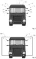
- Fig. 1 shows a schematic front view of a utility vehicle V, specifically of a truck.
- the utility vehicle V may comprise a towing vehicle V1 and a trailer V2.
- the utility vehicle V comprises a camera system 1 for providing image information of the area at the left and right side next to the utility vehicle V and behind the trailer V2 of the utility vehicle V.
- the camera system 1 comprises two pairs of cameras 2, 3, namely a first pair of cameras 2 arranged at the left side of the utility vehicle V and a second pair of cameras 3 arranged at the right side of the utility vehicle V.
- the first and second pair of cameras 2, 3 comprise rear-viewing cameras, i.e. the main capturing direction of the cameras is opposite to the forward driving direction.
- the first pair of cameras 2 provides image information of the left area next to and behind the utility vehicle V and the second pair of cameras 3 provides image information of the right area next to and behind the utility vehicle V.
- the images provided by the two pairs of cameras 2, 3 provide information of the space at the left and right side of the utility vehicle V and the space behind the utility vehicle V which is not occluded by the towing vehicle V1 or the trailer V2.
- Each pair of cameras 2, 3 comprises a first camera 2.1, 3.1 and a second camera 2.2, 3.2.
- the cameras of the pair of cameras 2, 3 are arranged one above the other, as shown in Fig. 1 .
- the first cameras 2.1, 3.1 build upper cameras which are arranged above and at a distance to the second cameras 2.2, 3.2, i.e. the second cameras 2.2, 3.2 build lower cameras, each second camera 2.2, 3.2 being arranged below a first camera 2.1, 3.1.
- the first cameras 2.1, 3.1 are arranged at the left, respectively, right side of the cabin 4 at a height level equal or near to (e.g. 5 cm, 10cm or 20 cm lower) the top outer edge 4.1 of the cabin 4.
- the first cameras 2.1, 3.1 arranged at the left and right side may be arranged at the same height level.
- the height of the first cameras 2.1, 3.1 may be in the range of 3.5m to 4m.
- the second cameras 2.2, 3.2 are arranged at a height level equal or near to (e.g. 5 cm, 10cm or 20 cm lower) the lower edge 4.1 of the side window SW of the cabin 4.
- the second cameras 2.2, 3.2 may be arranged at the height at which the lower edge of a rear view mirror is arranged.
- the second cameras 2.2, 3.2 arranged at the left and right side may be arranged at the same height level.
- the height of the second cameras 2.2, 3.2 may be in the range of 2m to 2.5m, specifically at 2.1m, 2.2m, 2.3m or 2.4m.
- the cameras 2.1, 2.2, 3.1, 3.2 are arranged by means of spacers 5 at the cabin 4.
- the spacers 5 are configured to provide a horizontal distance between the outer cabin wall and the respective camera. Thereby, the occlusion due to the trailer can be reduced and the coverage range of the cameras 2.1, 2.2, 3.1, 3.2 can be increased.
- Each pair of cameras 2, 3 forms a stereo camera system which is configured to determine distance information of detected objects by calculating a disparity map based on the pictures captured from both cameras and thereby developing a 3D point cloud.
- each stereo camera system may be configured to determine the speed of an object moving behind or at the respective side of the utility vehicle V.
- the cameras of the pair of cameras 2, 3 have a vertical distance of at least 0.5m in order to obtain reliable distance information by the respective stereo camera system.
- the cameras 2.1, 2.2, 3.1, 3.2 comprise a rectangular field of view FOV, i.e. the width of the field of view is smaller than the height of the field of view FOV.
- the cameras 2.1, 2.2, 3.1, 3.2 provide image information in portrait view
- the vertical coverage is higher than the horizontal coverage which is suitable in most cases for monitoring the side and back area of the utility vehicle V.
- the cameras 2.1, 2.2, 3.1, 3.2 may provide image information in landscape orientation, i.e. the width of the field of view may be greater than the height of the field of view FOV. Thereby a wider sideway field of view can be obtained which is beneficial for more narrow curve radii to be driven.
- the cameras may provide grayscale-type image information.
- grayscale-type image information instead of coloured image information improves sensitivity and the possibility to use information of the camera system 1 also during night which is useful because in the side and back area there is no illumination by lamps of the ego-vehicle.
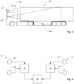
- Fig. 3 shows a lateral view of a utility vehicle comprising the proposed camera system 1.
- the horizontal aperture angle of the cameras 2.1, 2.2, 3.1, 3.2 may be between 15° and 25°, specifically 20° or essentially 20°.
- the vertical aperture angle of the cameras 2.1, 2.2, 3.1, 3.2 may be between 25° and 35°, specifically 30° or essentially 30°.
- the cameras 2.1, 2.2, 3.1, 3.2 may be aligned such that the inner image edge of the field of view FOV shows the side wall of the trailer V2 and field of view fans out laterally, as shown in Fig. 2 .
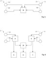
- Fig. 4 shows a schematic block diagram of a camera system 1.
- the first pair of cameras 2 is coupled with a first control unit 8 which is configured to provide a disparity map and a 3D point cloud of the left side area and back area next to the utility vehicle V.
- the second pair of cameras 3 is coupled with a second control unit 9 which is configured to provide a disparity map and a 3D point cloud of the right side area and back area next to the utility vehicle V.
- the first and second control units 8, 9 are coupled with a central control unit 10.
- the central control unit 10 may combine information provided by the first and second control units 8, 9 and may derive information and/or may provide decisions based on information of the first and second control units 8, 9.
- the central control unit 10 may be configured to perform object detection, extract obstacles and/or may determine driving decisions for autonomous driving functions.
- the camera system 1 may only comprise a central control unit 10 and the functionality of the first and second control units 8, 9 may be integrated in said central control unit 10.
- the central control unit 10 and/or the first and second control units 8, 9 implement a neural network for calculating stereo image information specifically a disparity map and 3D point cloud based on image information provided by the respective pair of cameras 2, 3.
- the neural network is a trained neural network which has been trained by labelled training data.
- the training data may be derived from real data, i.e. data captured in real driving situations and/or may be artificial training data.
- Fig. 6 shows a camera system 1 configured to replace rear view mirrors of the utility vehicle attached at the at the outer side walls of the cabin 4.
- the first control unit 8 may be coupled with a left rear view monitor 6 and the and second control unit 9 may be coupled with a right rear view monitor 7.
- the left rear view monitor 6 is configured to display image information of the left side area and the left back area of the utility vehicle V thereby being able to remove the left rear view mirror.
- the right rear view monitor 7 is configured to display image information of the right side area and the right back area of the utility vehicle V thereby being able to remove the right rear view mirror.
- the camera system 1 may comprise a central display unit 11 for providing information obtained by the cameras 2.1, 2.2, 3.1, 3.2 to the driver.
- the detection range of the system might be reduced.
- nonlinear optics that implement a higher magnification in the centre of the image and lower magnification towards the border might be used in the cameras 2.1, 2.2, 3.1, 3.2.
- the central control unit 10 may be configured to compensate said nonlinear magnification, i.e. calculate an image with equal magnification. Thereby, the viewing of images provided by the camera system is eased for human drives. However, an automated driving function might not require such equalization of magnification.
- the information regarding object distance and/or object speed derived by the stereo camera system can be used to highlight and/or apply such information to the respective objects in the respective rear view monitors 6, 7 and/or the display unit 11.
Landscapes
- Engineering & Computer Science (AREA)
- Multimedia (AREA)
- Theoretical Computer Science (AREA)
- Physics & Mathematics (AREA)
- General Physics & Mathematics (AREA)
- Computer Vision & Pattern Recognition (AREA)
- Mechanical Engineering (AREA)
- Artificial Intelligence (AREA)
- Health & Medical Sciences (AREA)
- Computing Systems (AREA)
- Databases & Information Systems (AREA)
- Evolutionary Computation (AREA)
- General Health & Medical Sciences (AREA)
- Medical Informatics (AREA)
- Software Systems (AREA)
- Signal Processing (AREA)
- Closed-Circuit Television Systems (AREA)
- Studio Devices (AREA)
Claims (13)
- Kamerasystem für ein Nutzfahrzeug (V) mit einer Kabine (4), wobei das Kamerasystem (1) zwei Paare von Kameras (2, 3) aufweist, wobei ein erstes Paar von Kameras (2) am linken Seitenabschnitt der Kabine (4) des Nutzfahrzeugs (V) angeordnet ist und ein zweites Paar von Kameras (3) am rechten Seitenabschnitt der Kabine (4) des Nutzfahrzeugs (V) angeordnet ist, wobei die Kameras (2.1, 2.2, 3.1, 3.2) des ersten und zweiten Paars von Kameras (2, 3) in einer vertikalen Richtung übereinander angeordnet sind, wobei das erste Paar von Kameras (2) ein Rückblick-Stereokamerasystem zum Bereitstellen von Bildinformationen und Abstandsinformationen eines Bereichs auf der linken Seite des Nutzfahrzeugs (V) ausbildet und das zweite Paar von Kameras (3) ein Rückblick-Stereokamerasystem zum Bereitstellen von Bildinformationen und Abstandsinformationen eines Bereichs auf der rechten Seite des Nutzfahrzeugs (V) ausbildet, wobei die Kameras (2.1, 2.2, 3.1, 3.2) des ersten und zweiten Paars von Kameras (2, 3) mittels eines oder mehrerer Abstandshalter (5) an der Kabine (4) des Nutzfahrzeugs (V) angeordnet sind, wobei die Abstandshalter (5) einen seitlichen Abstand der Kameras (2.1, 2.2, 3.1, 3.2) zur Kabine (4) bereitstellen und wobei die Kameras (2.1, 2.2, 3.1, 3.2) jedes Paars von Kameras (2, 3) einen vertikalen Abstand von mindestens 0,5 m aufweisen,
dadurch gekennzeichnet, dassdie Kameras (2.1, 2.2, 3.1, 3.2) ein rechteckiges oder im Wesentlichen rechteckiges Sichtfeld aufweisen und dadurch, dassdie Kameras (2.1, 2.2, 3.1, 3.2) so positioniert sind, dass sie ein Hochformat bereitstellen, und dadurch, dass es Folgendes aufweisteine Steuereinheit (8, 9, 10), die ein trainiertes neuronales Netzwerk zum Berechnen einer Disparitätskarte und von Abstandsinformationen zu Objekten implementiert, die in den durch die Kameras (2.1, 2.2, 3.1, 3.2) bereitgestellten Bildinformationen enthalten sind. - Kamerasystem nach Anspruch 1, wobei eine erste Kamera (2.1, 3.1) der Paare von Kameras (2, 3) als eine obere Kamera in einem Höhenbereich zwischen der Oberseite der Kabine (4) und der Oberkante eines Seitenfensters (SW) der Kabine (4) angeordnet ist.
- Kamerasystem nach Anspruch 1 oder 2, wobei eine zweite Kamera (2.2, 3.2) der Paare von Kameras (2, 3) als eine untere Kamera in einem Höhenbereich zwischen der Oberkante eines Seitenfensters (SW) und der Unterkante eines Seitenfensters (SW) angeordnet ist.
- Kamerasystem nach einem der vorhergehenden Ansprüche, wobei eine erste Kamera (2.1, 3.1) der Paare von Kameras (2, 3) als eine obere Kamera in einem Höhenbereich zwischen 3,5 m und 4 m angeordnet ist.
- Kamerasystem nach einem der vorhergehenden Ansprüche, wobei eine zweite Kamera (2.2, 3.3) der Paare von Kameras (2, 3) als eine untere Kamera in einem Höhenbereich zwischen 2 m und 3 m angeordnet ist.
- Kamerasystem nach einem der vorhergehenden Ansprüche, wobei die Kameras (2.1, 2.2, 3.1, 3.2) ein Sichtfeld mit einem vertikalen Aperturwinkel im Bereich zwischen 25° und 35° und einem horizontalen Aperturwinkel im Bereich zwischen 15° und 25° bereitstellen.
- Kamerasystem nach einem der vorhergehenden Ansprüche, wobei die Kameras (2.1, 2.2, 3.1, 3.2) vom Graustufentyp sind.
- Kamerasystem nach einem der vorhergehenden Ansprüche, wobei das erste Paar von Kameras (2) dazu ausgebildet ist, Bildinformationen zu einem linken Rückblickmonitor (6) bereitzustellen, und das zweite Paar von Kameras (3) dazu ausgebildet ist, Bildinformationen zu einem rechten Rückblickmonitor (7) als Ersatz für Rückspiegel bereitzustellen.
- Kamerasystem nach einem der vorhergehenden Ansprüche, wobei die Kameras (2.1, 2.2, 3.1, 3.2) eine nichtlineare Optik mit einer höheren Vergrößerung im mittleren Abschnitt des Sichtfeldes (FOV) als im Randbereich des Sichtfeldes (FOV) aufweisen.
- Kamerasystem nach Anspruch 9, wobei das Kamerasystem (1) eine Steuereinheit (8, 9, 10) aufweist, die dazu ausgebildet ist, die Vergrößerungsdifferenz zwischen dem mittleren Abschnitt und dem Randbereich des Sichtfeldes (FOV) auszugleichen.
- Kamerasystem nach einem der vorhergehenden Ansprüche, wobei das Kamerasystem (1) eine Steuereinheit (8, 9, 10) aufweist, die dazu ausgebildet ist, Informationen in Bezug auf eine Objektgeschwindigkeit und/oder Objektabstände eines oder mehrerer hinter dem Kamerasystem (1) angeordneter Objekte bereitzustellen.
- Kamerasystem nach Anspruch 11, wobei das Kamerasystem (1) einen linken Rückblickmonitor (6) und einen rechten Rückblickmonitor (7) und/oder eine Anzeigeeinheit (11) aufweist, die dazu ausgebildet sind, Rückblickbilder anzuzeigen, und wobei die Steuereinheit (8, 9, 10) dazu ausgebildet ist, an dem linken Rückblickmonitor (6), dem rechten Rückblickmonitor (7) und/oder der Anzeigeeinheit (11) bereitgestellte Objekte basierend auf Informationen in Bezug auf eine Objektgeschwindigkeit und/oder Objektabstände eines oder mehrerer hinter dem Kamerasystem angeordneter Objekte (1) hervorzuheben.
- Nutzfahrzeug, das ein Kamerasystem (1) nach einem der vorhergehenden Ansprüche aufweist.
Priority Applications (2)
| Application Number | Priority Date | Filing Date | Title |
|---|---|---|---|
| EP22155749.9A EP4223593B1 (de) | 2022-02-08 | 2022-02-08 | Stereokamerasystem für rückansicht |
| US18/166,293 US12469301B2 (en) | 2022-02-08 | 2023-02-08 | Rear-view stereo camera system |
Applications Claiming Priority (1)
| Application Number | Priority Date | Filing Date | Title |
|---|---|---|---|
| EP22155749.9A EP4223593B1 (de) | 2022-02-08 | 2022-02-08 | Stereokamerasystem für rückansicht |
Publications (2)
| Publication Number | Publication Date |
|---|---|
| EP4223593A1 EP4223593A1 (de) | 2023-08-09 |
| EP4223593B1 true EP4223593B1 (de) | 2025-01-01 |
Family
ID=80446570
Family Applications (1)
| Application Number | Title | Priority Date | Filing Date |
|---|---|---|---|
| EP22155749.9A Active EP4223593B1 (de) | 2022-02-08 | 2022-02-08 | Stereokamerasystem für rückansicht |
Country Status (2)
| Country | Link |
|---|---|
| US (1) | US12469301B2 (de) |
| EP (1) | EP4223593B1 (de) |
Families Citing this family (1)
| Publication number | Priority date | Publication date | Assignee | Title |
|---|---|---|---|---|
| CN117237393B (zh) * | 2023-11-06 | 2024-05-17 | 深圳金语科技有限公司 | 基于流媒体后视镜的图像处理方法、装置及计算机设备 |
Family Cites Families (13)
| Publication number | Priority date | Publication date | Assignee | Title |
|---|---|---|---|---|
| DE10008520A1 (de) | 1999-02-24 | 2000-08-31 | Schoenherr Hans Joerg | Vorrichtung und Verfahren zur Gewinnung von Stereobildpaaren mit einer Rotationspanoramakamera für Anwendungen der Photogrammetrie und der Visualisierung |
| DE10343866A1 (de) | 2003-09-23 | 2005-04-21 | Daimler Chrysler Ag | Stereokameraanordnung |
| US8199975B2 (en) * | 2006-12-12 | 2012-06-12 | Cognex Corporation | System and method for side vision detection of obstacles for vehicles |
| US9235990B2 (en) * | 2011-11-25 | 2016-01-12 | Honda Motor Co., Ltd. | Vehicle periphery monitoring device |
| EP3010761B1 (de) * | 2013-06-21 | 2019-07-24 | Magna Electronics Inc. | Fahrzeugsichtsystem |
| MA36097B1 (fr) * | 2013-07-08 | 2016-01-29 | Mascir Morrocan Foundation For Advanced Science Innovation & Res | Système mono-caméra d'estimation de vitesse de véhicule par traitement vidéo avec calibration multi-caméra par effet stéréoscopique |
| US20160026881A1 (en) * | 2014-07-22 | 2016-01-28 | Vislab S.R.L. | Lateral obstacle detection apparatus for a motor vehicle, motor vehicle comprising that apparatus and process for detecting lateral obstacles during the travel of a motor vehicle |
| DE102017006176A1 (de) | 2017-06-29 | 2017-12-21 | Daimler Ag | Stereokamera zur Umgebungserfassung für ein Fahrzeug |
| JP2020051942A (ja) * | 2018-09-27 | 2020-04-02 | 株式会社Subaru | 車両の走行環境検出装置及び走行制御システム |
| DE102019213607A1 (de) * | 2019-09-06 | 2021-03-11 | Continental Automotive Gmbh | 3D-Darstellung in digitalem Fahrzeugrückspiegel |
| KR102785227B1 (ko) * | 2020-01-22 | 2025-03-25 | 노다르 인크. | 비-강성 스테레오 비전 카메라 시스템 |
| US12456046B2 (en) * | 2020-04-20 | 2025-10-28 | Nvidia Corporation | Distance determinations using one or more neural networks |
| US11343485B1 (en) * | 2020-08-24 | 2022-05-24 | Ambarella International Lp | Virtual horizontal stereo camera |
-
2022
- 2022-02-08 EP EP22155749.9A patent/EP4223593B1/de active Active
-
2023
- 2023-02-08 US US18/166,293 patent/US12469301B2/en active Active
Also Published As
| Publication number | Publication date |
|---|---|
| US20230252793A1 (en) | 2023-08-10 |
| US12469301B2 (en) | 2025-11-11 |
| EP4223593A1 (de) | 2023-08-09 |
Similar Documents
| Publication | Publication Date | Title |
|---|---|---|
| US11794647B2 (en) | Vehicular vision system having a plurality of cameras | |
| US12001213B2 (en) | Vehicle and trailer maneuver assist system | |
| US11505123B2 (en) | Vehicular camera monitoring system with stereographic display | |
| US11472338B2 (en) | Method for displaying reduced distortion video images via a vehicular vision system | |
| US10183621B2 (en) | Vehicular image processing apparatus and vehicular image processing system | |
| US20200148114A1 (en) | Vehicular vision system with reduced distortion display | |
| US8537221B2 (en) | Lane change control system | |
| US20070206835A1 (en) | Method of Processing Images Photographed by Plural Cameras And Apparatus For The Same | |
| US20160094808A1 (en) | All-round view monitoring system for a motor vehicle | |
| US11584299B2 (en) | Driver-assisting system for an industrial vehicle | |
| US20170347036A1 (en) | Driver Assistance System | |
| JP7028536B2 (ja) | 表示システム | |
| EP4395356A1 (de) | Bilderfassungsvorrichtung, bewegliche vorrichtung und speichermedium | |
| US11377027B2 (en) | Image processing apparatus, imaging apparatus, driving assistance apparatus, mobile body, and image processing method | |
| EP4223593B1 (de) | Stereokamerasystem für rückansicht | |
| US11400861B2 (en) | Camera monitoring system | |
| US20080198227A1 (en) | Night Vision System | |
| EP2902262B1 (de) | Kameraanordnung, System mit einer Kameraanordnung und Fahrzeug mit einer Kameraanordnung | |
| US10889245B2 (en) | Vehicle imaging system | |
| KR20220161611A (ko) | 시점변경 기능을 갖는 avm 시스템 | |
| KR20250069426A (ko) | 트레일러의 위치를 결정하고 검증하는 카메라 기반 시스템 및 방법 |
Legal Events
| Date | Code | Title | Description |
|---|---|---|---|
| PUAI | Public reference made under article 153(3) epc to a published international application that has entered the european phase |
Free format text: ORIGINAL CODE: 0009012 |
|
| STAA | Information on the status of an ep patent application or granted ep patent |
Free format text: STATUS: THE APPLICATION HAS BEEN PUBLISHED |
|
| AK | Designated contracting states |
Kind code of ref document: A1 Designated state(s): AL AT BE BG CH CY CZ DE DK EE ES FI FR GB GR HR HU IE IS IT LI LT LU LV MC MK MT NL NO PL PT RO RS SE SI SK SM TR |
|
| STAA | Information on the status of an ep patent application or granted ep patent |
Free format text: STATUS: REQUEST FOR EXAMINATION WAS MADE |
|
| STAA | Information on the status of an ep patent application or granted ep patent |
Free format text: STATUS: EXAMINATION IS IN PROGRESS |
|
| 17P | Request for examination filed |
Effective date: 20240209 |
|
| RBV | Designated contracting states (corrected) |
Designated state(s): AL AT BE BG CH CY CZ DE DK EE ES FI FR GB GR HR HU IE IS IT LI LT LU LV MC MK MT NL NO PL PT RO RS SE SI SK SM TR |
|
| 17Q | First examination report despatched |
Effective date: 20240304 |
|
| GRAP | Despatch of communication of intention to grant a patent |
Free format text: ORIGINAL CODE: EPIDOSNIGR1 |
|
| STAA | Information on the status of an ep patent application or granted ep patent |
Free format text: STATUS: GRANT OF PATENT IS INTENDED |
|
| INTG | Intention to grant announced |
Effective date: 20240731 |
|
| GRAS | Grant fee paid |
Free format text: ORIGINAL CODE: EPIDOSNIGR3 |
|
| GRAA | (expected) grant |
Free format text: ORIGINAL CODE: 0009210 |
|
| STAA | Information on the status of an ep patent application or granted ep patent |
Free format text: STATUS: THE PATENT HAS BEEN GRANTED |
|
| AK | Designated contracting states |
Kind code of ref document: B1 Designated state(s): AL AT BE BG CH CY CZ DE DK EE ES FI FR GB GR HR HU IE IS IT LI LT LU LV MC MK MT NL NO PL PT RO RS SE SI SK SM TR |
|
| REG | Reference to a national code |
Ref country code: GB Ref legal event code: FG4D |
|
| REG | Reference to a national code |
Ref country code: CH Ref legal event code: EP |
|
| REG | Reference to a national code |
Ref country code: DE Ref legal event code: R096 Ref document number: 602022009204 Country of ref document: DE |
|
| REG | Reference to a national code |
Ref country code: IE Ref legal event code: FG4D |
|
| PGFP | Annual fee paid to national office [announced via postgrant information from national office to epo] |
Ref country code: DE Payment date: 20250228 Year of fee payment: 4 |
|
| PGFP | Annual fee paid to national office [announced via postgrant information from national office to epo] |
Ref country code: AT Payment date: 20250417 Year of fee payment: 4 |
|
| REG | Reference to a national code |
Ref country code: LT Ref legal event code: MG9D |
|
| REG | Reference to a national code |
Ref country code: NL Ref legal event code: MP Effective date: 20250101 |
|
| REG | Reference to a national code |
Ref country code: AT Ref legal event code: MK05 Ref document number: 1755937 Country of ref document: AT Kind code of ref document: T Effective date: 20250101 |
|
| PG25 | Lapsed in a contracting state [announced via postgrant information from national office to epo] |
Ref country code: NL Free format text: LAPSE BECAUSE OF FAILURE TO SUBMIT A TRANSLATION OF THE DESCRIPTION OR TO PAY THE FEE WITHIN THE PRESCRIBED TIME-LIMIT Effective date: 20250101 |
|
| PG25 | Lapsed in a contracting state [announced via postgrant information from national office to epo] |
Ref country code: FI Free format text: LAPSE BECAUSE OF FAILURE TO SUBMIT A TRANSLATION OF THE DESCRIPTION OR TO PAY THE FEE WITHIN THE PRESCRIBED TIME-LIMIT Effective date: 20250101 |
|
| PG25 | Lapsed in a contracting state [announced via postgrant information from national office to epo] |
Ref country code: PL Free format text: LAPSE BECAUSE OF FAILURE TO SUBMIT A TRANSLATION OF THE DESCRIPTION OR TO PAY THE FEE WITHIN THE PRESCRIBED TIME-LIMIT Effective date: 20250101 |
|
| PG25 | Lapsed in a contracting state [announced via postgrant information from national office to epo] |
Ref country code: ES Free format text: LAPSE BECAUSE OF FAILURE TO SUBMIT A TRANSLATION OF THE DESCRIPTION OR TO PAY THE FEE WITHIN THE PRESCRIBED TIME-LIMIT Effective date: 20250101 |
|
| REG | Reference to a national code |
Ref country code: DE Ref legal event code: R081 Ref document number: 602022009204 Country of ref document: DE Owner name: AUMOVIO AUTONOMOUS MOBILITY GERMANY GMBH, DE Free format text: FORMER OWNER: CONTINENTAL AUTONOMOUS MOBILITY GERMANY GMBH, 85057 INGOLSTADT, DE |
|
| PG25 | Lapsed in a contracting state [announced via postgrant information from national office to epo] |
Ref country code: IS Free format text: LAPSE BECAUSE OF FAILURE TO SUBMIT A TRANSLATION OF THE DESCRIPTION OR TO PAY THE FEE WITHIN THE PRESCRIBED TIME-LIMIT Effective date: 20250501 Ref country code: NO Free format text: LAPSE BECAUSE OF FAILURE TO SUBMIT A TRANSLATION OF THE DESCRIPTION OR TO PAY THE FEE WITHIN THE PRESCRIBED TIME-LIMIT Effective date: 20250401 |
|
| PG25 | Lapsed in a contracting state [announced via postgrant information from national office to epo] |
Ref country code: HR Free format text: LAPSE BECAUSE OF FAILURE TO SUBMIT A TRANSLATION OF THE DESCRIPTION OR TO PAY THE FEE WITHIN THE PRESCRIBED TIME-LIMIT Effective date: 20250101 |
|
| PG25 | Lapsed in a contracting state [announced via postgrant information from national office to epo] |
Ref country code: LV Free format text: LAPSE BECAUSE OF FAILURE TO SUBMIT A TRANSLATION OF THE DESCRIPTION OR TO PAY THE FEE WITHIN THE PRESCRIBED TIME-LIMIT Effective date: 20250101 Ref country code: PT Free format text: LAPSE BECAUSE OF FAILURE TO SUBMIT A TRANSLATION OF THE DESCRIPTION OR TO PAY THE FEE WITHIN THE PRESCRIBED TIME-LIMIT Effective date: 20250502 |
|
| PG25 | Lapsed in a contracting state [announced via postgrant information from national office to epo] |
Ref country code: BG Free format text: LAPSE BECAUSE OF FAILURE TO SUBMIT A TRANSLATION OF THE DESCRIPTION OR TO PAY THE FEE WITHIN THE PRESCRIBED TIME-LIMIT Effective date: 20250101 Ref country code: GR Free format text: LAPSE BECAUSE OF FAILURE TO SUBMIT A TRANSLATION OF THE DESCRIPTION OR TO PAY THE FEE WITHIN THE PRESCRIBED TIME-LIMIT Effective date: 20250402 |
|
| PG25 | Lapsed in a contracting state [announced via postgrant information from national office to epo] |
Ref country code: AT Free format text: LAPSE BECAUSE OF FAILURE TO SUBMIT A TRANSLATION OF THE DESCRIPTION OR TO PAY THE FEE WITHIN THE PRESCRIBED TIME-LIMIT Effective date: 20250101 |
|
| PG25 | Lapsed in a contracting state [announced via postgrant information from national office to epo] |
Ref country code: CZ Free format text: LAPSE BECAUSE OF FAILURE TO SUBMIT A TRANSLATION OF THE DESCRIPTION OR TO PAY THE FEE WITHIN THE PRESCRIBED TIME-LIMIT Effective date: 20250101 |
|
| RAP4 | Party data changed (patent owner data changed or rights of a patent transferred) |
Owner name: AUMOVIO AUTONOMOUS MOBILITY GERMANY GMBH |
|
| PG25 | Lapsed in a contracting state [announced via postgrant information from national office to epo] |
Ref country code: SE Free format text: LAPSE BECAUSE OF FAILURE TO SUBMIT A TRANSLATION OF THE DESCRIPTION OR TO PAY THE FEE WITHIN THE PRESCRIBED TIME-LIMIT Effective date: 20250101 |
|
| REG | Reference to a national code |
Ref country code: CH Ref legal event code: PL |
|
| REG | Reference to a national code |
Ref country code: DE Ref legal event code: R097 Ref document number: 602022009204 Country of ref document: DE |
|
| PG25 | Lapsed in a contracting state [announced via postgrant information from national office to epo] |
Ref country code: SM Free format text: LAPSE BECAUSE OF FAILURE TO SUBMIT A TRANSLATION OF THE DESCRIPTION OR TO PAY THE FEE WITHIN THE PRESCRIBED TIME-LIMIT Effective date: 20250101 |
|
| PG25 | Lapsed in a contracting state [announced via postgrant information from national office to epo] |
Ref country code: DK Free format text: LAPSE BECAUSE OF FAILURE TO SUBMIT A TRANSLATION OF THE DESCRIPTION OR TO PAY THE FEE WITHIN THE PRESCRIBED TIME-LIMIT Effective date: 20250101 |
|
| PG25 | Lapsed in a contracting state [announced via postgrant information from national office to epo] |
Ref country code: MC Free format text: LAPSE BECAUSE OF FAILURE TO SUBMIT A TRANSLATION OF THE DESCRIPTION OR TO PAY THE FEE WITHIN THE PRESCRIBED TIME-LIMIT Effective date: 20250101 |
|
| PG25 | Lapsed in a contracting state [announced via postgrant information from national office to epo] |
Ref country code: LU Free format text: LAPSE BECAUSE OF NON-PAYMENT OF DUE FEES Effective date: 20250208 Ref country code: IT Free format text: LAPSE BECAUSE OF FAILURE TO SUBMIT A TRANSLATION OF THE DESCRIPTION OR TO PAY THE FEE WITHIN THE PRESCRIBED TIME-LIMIT Effective date: 20250101 |
|
| PG25 | Lapsed in a contracting state [announced via postgrant information from national office to epo] |
Ref country code: CH Free format text: LAPSE BECAUSE OF NON-PAYMENT OF DUE FEES Effective date: 20250228 |
|
| PG25 | Lapsed in a contracting state [announced via postgrant information from national office to epo] |
Ref country code: EE Free format text: LAPSE BECAUSE OF FAILURE TO SUBMIT A TRANSLATION OF THE DESCRIPTION OR TO PAY THE FEE WITHIN THE PRESCRIBED TIME-LIMIT Effective date: 20250101 |
|
| PG25 | Lapsed in a contracting state [announced via postgrant information from national office to epo] |
Ref country code: RO Free format text: LAPSE BECAUSE OF FAILURE TO SUBMIT A TRANSLATION OF THE DESCRIPTION OR TO PAY THE FEE WITHIN THE PRESCRIBED TIME-LIMIT Effective date: 20250101 |
|
| PG25 | Lapsed in a contracting state [announced via postgrant information from national office to epo] |
Ref country code: SK Free format text: LAPSE BECAUSE OF FAILURE TO SUBMIT A TRANSLATION OF THE DESCRIPTION OR TO PAY THE FEE WITHIN THE PRESCRIBED TIME-LIMIT Effective date: 20250101 |
|
| PLBE | No opposition filed within time limit |
Free format text: ORIGINAL CODE: 0009261 |
|
| STAA | Information on the status of an ep patent application or granted ep patent |
Free format text: STATUS: NO OPPOSITION FILED WITHIN TIME LIMIT |
|
| REG | Reference to a national code |
Ref country code: BE Ref legal event code: MM Effective date: 20250228 |
|
| 26N | No opposition filed |
Effective date: 20251002 |
|
| PG25 | Lapsed in a contracting state [announced via postgrant information from national office to epo] |
Ref country code: FR Free format text: LAPSE BECAUSE OF NON-PAYMENT OF DUE FEES Effective date: 20250301 |
|
| PG25 | Lapsed in a contracting state [announced via postgrant information from national office to epo] |
Ref country code: BE Free format text: LAPSE BECAUSE OF NON-PAYMENT OF DUE FEES Effective date: 20250228 |
|
| PG25 | Lapsed in a contracting state [announced via postgrant information from national office to epo] |
Ref country code: IE Free format text: LAPSE BECAUSE OF NON-PAYMENT OF DUE FEES Effective date: 20250208 |