EP4223430A1 - Container manufacturing method and container manufacturing device - Google Patents
Container manufacturing method and container manufacturing device Download PDFInfo
- Publication number
- EP4223430A1 EP4223430A1 EP21874881.2A EP21874881A EP4223430A1 EP 4223430 A1 EP4223430 A1 EP 4223430A1 EP 21874881 A EP21874881 A EP 21874881A EP 4223430 A1 EP4223430 A1 EP 4223430A1
- Authority
- EP
- European Patent Office
- Prior art keywords
- diameter
- container
- manufacturing
- tapered
- cylindrical portion
- Prior art date
- Legal status (The legal status is an assumption and is not a legal conclusion. Google has not performed a legal analysis and makes no representation as to the accuracy of the status listed.)
- Withdrawn
Links
- 238000004519 manufacturing process Methods 0.000 title claims abstract description 72
- 238000000034 method Methods 0.000 claims abstract description 46
- 238000003825 pressing Methods 0.000 claims abstract description 37
- 229910052751 metal Inorganic materials 0.000 claims abstract description 26
- 239000002184 metal Substances 0.000 claims abstract description 26
- 230000002093 peripheral effect Effects 0.000 claims description 16
- 235000013361 beverage Nutrition 0.000 description 8
- 238000010586 diagram Methods 0.000 description 6
- 239000000463 material Substances 0.000 description 6
- 239000004033 plastic Substances 0.000 description 6
- 229920003023 plastic Polymers 0.000 description 6
- 239000000853 adhesive Substances 0.000 description 3
- 230000001070 adhesive effect Effects 0.000 description 3
- 230000004323 axial length Effects 0.000 description 3
- 239000011324 bead Substances 0.000 description 3
- 230000036544 posture Effects 0.000 description 3
- 229910000838 Al alloy Inorganic materials 0.000 description 2
- 239000012790 adhesive layer Substances 0.000 description 2
- 230000005484 gravity Effects 0.000 description 2
- 239000010410 layer Substances 0.000 description 2
- 238000000465 moulding Methods 0.000 description 2
- 229920000139 polyethylene terephthalate Polymers 0.000 description 2
- 239000005020 polyethylene terephthalate Substances 0.000 description 2
- 238000004064 recycling Methods 0.000 description 2
- 238000000926 separation method Methods 0.000 description 2
- 239000002699 waste material Substances 0.000 description 2
- 230000037303 wrinkles Effects 0.000 description 2
- 239000004831 Hot glue Substances 0.000 description 1
- 229910052782 aluminium Inorganic materials 0.000 description 1
- XAGFODPZIPBFFR-UHFFFAOYSA-N aluminium Chemical compound [Al] XAGFODPZIPBFFR-UHFFFAOYSA-N 0.000 description 1
- 238000007796 conventional method Methods 0.000 description 1
- 230000000694 effects Effects 0.000 description 1
- 238000003912 environmental pollution Methods 0.000 description 1
- 239000011888 foil Substances 0.000 description 1
- 239000004922 lacquer Substances 0.000 description 1
- 239000002648 laminated material Substances 0.000 description 1
- 230000007774 longterm Effects 0.000 description 1
- 239000007769 metal material Substances 0.000 description 1
- 239000000203 mixture Substances 0.000 description 1
- -1 polyethylene terephthalate Polymers 0.000 description 1
- 239000011347 resin Substances 0.000 description 1
- 229920005989 resin Polymers 0.000 description 1
- 239000000565 sealant Substances 0.000 description 1
- 238000007789 sealing Methods 0.000 description 1
- 238000003860 storage Methods 0.000 description 1
- 238000009966 trimming Methods 0.000 description 1
- 238000004804 winding Methods 0.000 description 1
Images





Classifications
-
- B—PERFORMING OPERATIONS; TRANSPORTING
- B21—MECHANICAL METAL-WORKING WITHOUT ESSENTIALLY REMOVING MATERIAL; PUNCHING METAL
- B21D—WORKING OR PROCESSING OF SHEET METAL OR METAL TUBES, RODS OR PROFILES WITHOUT ESSENTIALLY REMOVING MATERIAL; PUNCHING METAL
- B21D22/00—Shaping without cutting, by stamping, spinning, or deep-drawing
- B21D22/20—Deep-drawing
- B21D22/26—Deep-drawing for making peculiarly, e.g. irregularly, shaped articles
-
- B—PERFORMING OPERATIONS; TRANSPORTING
- B21—MECHANICAL METAL-WORKING WITHOUT ESSENTIALLY REMOVING MATERIAL; PUNCHING METAL
- B21D—WORKING OR PROCESSING OF SHEET METAL OR METAL TUBES, RODS OR PROFILES WITHOUT ESSENTIALLY REMOVING MATERIAL; PUNCHING METAL
- B21D51/00—Making hollow objects
- B21D51/16—Making hollow objects characterised by the use of the objects
- B21D51/26—Making hollow objects characterised by the use of the objects cans or tins; Closing same in a permanent manner
- B21D51/2646—Of particular non cylindrical shape, e.g. conical, rectangular, polygonal, bulged
-
- A—HUMAN NECESSITIES
- A47—FURNITURE; DOMESTIC ARTICLES OR APPLIANCES; COFFEE MILLS; SPICE MILLS; SUCTION CLEANERS IN GENERAL
- A47G—HOUSEHOLD OR TABLE EQUIPMENT
- A47G19/00—Table service
-
- B—PERFORMING OPERATIONS; TRANSPORTING
- B21—MECHANICAL METAL-WORKING WITHOUT ESSENTIALLY REMOVING MATERIAL; PUNCHING METAL
- B21D—WORKING OR PROCESSING OF SHEET METAL OR METAL TUBES, RODS OR PROFILES WITHOUT ESSENTIALLY REMOVING MATERIAL; PUNCHING METAL
- B21D22/00—Shaping without cutting, by stamping, spinning, or deep-drawing
- B21D22/02—Stamping using rigid devices or tools
- B21D22/025—Stamping using rigid devices or tools for tubular articles
-
- B—PERFORMING OPERATIONS; TRANSPORTING
- B21—MECHANICAL METAL-WORKING WITHOUT ESSENTIALLY REMOVING MATERIAL; PUNCHING METAL
- B21D—WORKING OR PROCESSING OF SHEET METAL OR METAL TUBES, RODS OR PROFILES WITHOUT ESSENTIALLY REMOVING MATERIAL; PUNCHING METAL
- B21D22/00—Shaping without cutting, by stamping, spinning, or deep-drawing
- B21D22/20—Deep-drawing
- B21D22/28—Deep-drawing of cylindrical articles using consecutive dies
-
- B—PERFORMING OPERATIONS; TRANSPORTING
- B21—MECHANICAL METAL-WORKING WITHOUT ESSENTIALLY REMOVING MATERIAL; PUNCHING METAL
- B21D—WORKING OR PROCESSING OF SHEET METAL OR METAL TUBES, RODS OR PROFILES WITHOUT ESSENTIALLY REMOVING MATERIAL; PUNCHING METAL
- B21D22/00—Shaping without cutting, by stamping, spinning, or deep-drawing
- B21D22/20—Deep-drawing
- B21D22/30—Deep-drawing to finish articles formed by deep-drawing
-
- B—PERFORMING OPERATIONS; TRANSPORTING
- B21—MECHANICAL METAL-WORKING WITHOUT ESSENTIALLY REMOVING MATERIAL; PUNCHING METAL
- B21D—WORKING OR PROCESSING OF SHEET METAL OR METAL TUBES, RODS OR PROFILES WITHOUT ESSENTIALLY REMOVING MATERIAL; PUNCHING METAL
- B21D51/00—Making hollow objects
- B21D51/16—Making hollow objects characterised by the use of the objects
- B21D51/18—Making hollow objects characterised by the use of the objects vessels, e.g. tubs, vats, tanks, sinks, or the like
-
- B—PERFORMING OPERATIONS; TRANSPORTING
- B21—MECHANICAL METAL-WORKING WITHOUT ESSENTIALLY REMOVING MATERIAL; PUNCHING METAL
- B21D—WORKING OR PROCESSING OF SHEET METAL OR METAL TUBES, RODS OR PROFILES WITHOUT ESSENTIALLY REMOVING MATERIAL; PUNCHING METAL
- B21D51/00—Making hollow objects
- B21D51/16—Making hollow objects characterised by the use of the objects
- B21D51/26—Making hollow objects characterised by the use of the objects cans or tins; Closing same in a permanent manner
-
- B—PERFORMING OPERATIONS; TRANSPORTING
- B21—MECHANICAL METAL-WORKING WITHOUT ESSENTIALLY REMOVING MATERIAL; PUNCHING METAL
- B21D—WORKING OR PROCESSING OF SHEET METAL OR METAL TUBES, RODS OR PROFILES WITHOUT ESSENTIALLY REMOVING MATERIAL; PUNCHING METAL
- B21D51/00—Making hollow objects
- B21D51/16—Making hollow objects characterised by the use of the objects
- B21D51/26—Making hollow objects characterised by the use of the objects cans or tins; Closing same in a permanent manner
- B21D51/2669—Transforming the shape of formed can bodies; Forming can bodies from flattened tubular blanks; Flattening can bodies
-
- B—PERFORMING OPERATIONS; TRANSPORTING
- B65—CONVEYING; PACKING; STORING; HANDLING THIN OR FILAMENTARY MATERIAL
- B65D—CONTAINERS FOR STORAGE OR TRANSPORT OF ARTICLES OR MATERIALS, e.g. BAGS, BARRELS, BOTTLES, BOXES, CANS, CARTONS, CRATES, DRUMS, JARS, TANKS, HOPPERS, FORWARDING CONTAINERS; ACCESSORIES, CLOSURES, OR FITTINGS THEREFOR; PACKAGING ELEMENTS; PACKAGES
- B65D21/00—Nestable, stackable or joinable containers; Containers of variable capacity
- B65D21/02—Containers specially shaped, or provided with fittings or attachments, to facilitate nesting, stacking, or joining together
- B65D21/0209—Containers specially shaped, or provided with fittings or attachments, to facilitate nesting, stacking, or joining together stackable or joined together one-upon-the-other in the upright or upside-down position
- B65D21/0212—Containers presenting local stacking elements protruding from the upper or lower edge of a side wall, e.g. handles, lugs, ribs, grooves
-
- B—PERFORMING OPERATIONS; TRANSPORTING
- B65—CONVEYING; PACKING; STORING; HANDLING THIN OR FILAMENTARY MATERIAL
- B65D—CONTAINERS FOR STORAGE OR TRANSPORT OF ARTICLES OR MATERIALS, e.g. BAGS, BARRELS, BOTTLES, BOXES, CANS, CARTONS, CRATES, DRUMS, JARS, TANKS, HOPPERS, FORWARDING CONTAINERS; ACCESSORIES, CLOSURES, OR FITTINGS THEREFOR; PACKAGING ELEMENTS; PACKAGES
- B65D1/00—Rigid or semi-rigid containers having bodies formed in one piece, e.g. by casting metallic material, by moulding plastics, by blowing vitreous material, by throwing ceramic material, by moulding pulped fibrous material or by deep-drawing operations performed on sheet material
- B65D1/22—Boxes or like containers with side walls of substantial depth for enclosing contents
- B65D1/26—Thin-walled containers, e.g. formed by deep-drawing operations
- B65D1/265—Drinking cups
-
- B—PERFORMING OPERATIONS; TRANSPORTING
- B65—CONVEYING; PACKING; STORING; HANDLING THIN OR FILAMENTARY MATERIAL
- B65D—CONTAINERS FOR STORAGE OR TRANSPORT OF ARTICLES OR MATERIALS, e.g. BAGS, BARRELS, BOTTLES, BOXES, CANS, CARTONS, CRATES, DRUMS, JARS, TANKS, HOPPERS, FORWARDING CONTAINERS; ACCESSORIES, CLOSURES, OR FITTINGS THEREFOR; PACKAGING ELEMENTS; PACKAGES
- B65D7/00—Containers having bodies formed by interconnecting or uniting two or more rigid, or substantially rigid, components made wholly or mainly of metal
- B65D7/02—Containers having bodies formed by interconnecting or uniting two or more rigid, or substantially rigid, components made wholly or mainly of metal characterised by shape
- B65D7/04—Containers having bodies formed by interconnecting or uniting two or more rigid, or substantially rigid, components made wholly or mainly of metal characterised by shape of curved cross-section, e.g. cans of circular or elliptical cross-section
Definitions
- the present invention relates to a method for manufacturing a container made of metal, open on an upper face side, and including a bottom portion and a body portion and to an apparatus for manufacturing a container.
- containers open on an upper face side, containers made of metal that are washed and used many times, such as those used for tableware, are well known.
- a certain plate thickness is necessary to increase strength, resulting in higher material costs and molding costs and a heavier weight, thus making the container a highly problematic alternative to containers made of paper, plastic, or the like.
- a container made of metal and having an open upper face side is not suitable in shape or structure for being stored and transported while empty and being used by a user while open.
- An object of the present invention is to solve the problems described above, and to provide a method for manufacturing a container and an apparatus for manufacturing a container, by which it is possible to easily manufacture a container having a body portion with a shape that expands outward toward an upper face side of the body portion.
- a method for manufacturing a container according to the present invention is a method for manufacturing a container made of metal, including a bottom portion and a body portion, being open on an upper face side, and having a shape in which the body portion expands outward toward the upper face side.
- the problem is solved by including a stretch forming step of expanding a diameter of a stepped cup body made of metal and having a small-diameter cylindrical portion having a bottomed cylindrical shape and a large-diameter cylindrical portion with an opening on an upper face side and contiguous to an upper end of the small-diameter cylindrical portion via a step portion by operating a diameter expanding punch having a tapered pressing portion that is smaller in diameter than an inner diameter of the large-diameter cylindrical portion and larger in diameter than an inner diameter of the small-diameter cylindrical portion of the stepped cup body along a cylindrical axis direction from an opening side of the large-diameter cylindrical portion, and performing the stretch forming step at least once.
- An apparatus for manufacturing a container according to the present invention is an apparatus for manufacturing a container made of metal, including a bottom portion and a body portion, being open on an upper face side, and having a shape in which the body portion expands outward toward the upper face side.
- the apparatus includes at least one stretch forming die, each stretch forming die including a diameter expanding punch having a tapered pressing portion that is configured to expand a diameter of a stepped cup body made of metal and having a small-diameter cylindrical portion having a bottomed cylindrical shape and a large-diameter cylindrical portion with an opening on an upper face side and contiguous to an upper end of the small-diameter cylindrical portion via a step portion by pressing along a cylindrical axis direction from an opening side of the large-diameter cylindrical portion and that is smaller in diameter than an inner diameter of the large-diameter cylindrical portion and larger in diameter than an inner diameter of the small-diameter cylindrical portion of the stepped cup body.
- the diameter of the stepped cup body can be expanded without causing damage to the cup body, such as wrinkles or cracks.
- the manufacturing facility can be downsized, and the manufacturing process can be sped up.
- the body portion of the container can be reliably formed into the tapered shape over the wide height range.
- the stretch forming step from 2 to 10 times, the body portion of the container can be more reliably formed into the tapered shape over the wide height range.
- an angle of the step portion of the stepped cup body to a plane perpendicular to an axial direction of the stepped cup body (horizontal plane) is from 0° to 60°, the stepped cup body can be easily formed into the tapered shape over the wide height range while suppressing the occurrence of wrinkles or the like.
- a diameter of a tapered pressing portion of a diameter expanding punch used in a stretch forming step performed earlier and a diameter of a tapered pressing portion of a diameter expanding punch used in a stretch forming step performed subsequently are different from each other, so that the body portion of the container can be reliably formed into a tapered shape over a wide height range.
- the container by forming the body portion so that a line connecting an outer peripheral face at 10% height and an outer peripheral face at 90% height from a lowermost portion expands outward at an angle of from 2° to 15°, preferably from 3° to 10° (body taper angle) when a total height of the container is 100%, the container can be manufactured with a shape that has high strength, is easy to stack, and is easy for a user to hold, while suppressing toppling when the center of gravity is raised by containing beverages or the like.
- Containers formed with the body taper angle of more than 15° increase the distance between adjacent containers when arranged in upright postures, resulting in inefficient storage.
- containers formed with the body taper angle of less than 2° are difficult to separate when stacked containers are separated because the stacked containers stick to each other or the like.
- a projecting portion of the container placed above projecting from the container placed below has a height of 20 mm or less from an upper end of the container placed below, so that the height of a plurality of stacked containers can be reduced.
- the containers when transporting and transferring containers to a facility for filling beverages, food, or the like, a lid attachment facility, or the like, the containers can be transported and transferred in a stacked state, thereby improving efficiency in cans manufacturing, or the like by filling beverages, food, or the like, and then sealing the filled cans.
- the containers can be manufactured with good self-standing stability.
- the thickness of the bottom portion is 0.35 mm or less
- the thickness of the body portion is from 0.10 to 0.22 mm in a height range of 50 ⁇ 10% when the total height of the container is 100%. This makes it possible to reduce the material costs and the forming costs and lighten the weight, and obtain a container that is formed into a shape in which a line connecting an outer peripheral face at 10% height and an outer peripheral face at 90% height from the lowermost portion expands upward and outward at an angle of from 3° to 10° when the total height of the container is 100% (a more suitable shape).
- a ratio of the projecting portion to a height of the container is preferably 5% to 9%.
- the body portion by making the body portion have a contact portion that prevents the body portion from coming into close contact with another container by reducing the contact area with the other container, it is possible to obtain containers in which the body portions are reliably prevented from coming into close contact with each other when a plurality of containers are stacked, and that are further improved in ease of separation because the portions other than the contact portion are non-contact and circulation of air between the containers can be ensured when individually separating the stacked plurality of containers.
- a container manufactured by a method for manufacturing a container according to the present invention will be described below.
- the container manufactured by the method for manufacturing a container according to the present invention is a container 100 that includes a bottom portion 120 and a body portion 110, is made of metal, has an upper opening 101 open on an upper face side, and can be replaced in shape with a well-known paper cup or plastic cup.
- the body portion 110 of the container 100 has a tapered portion 111 having an inverted truncated cone shape (tapered shape) that expands outward toward an upper side (upper opening 101 side), an upper side portion 113 that is continuous between the tapered portion 111 and the upper opening 101, and a lower side portion 114 that is continuous between the tapered portion 111 and the bottom portion 120.
- the tapered portion 111 of the body portion 110 has, for example, a linear and uniform tapered shape in a cross-sectional view, and an angle ⁇ thereof is 5°.
- the upper side portion 113 and the lower side portion 114 do not expand outward and have an approximately cylindrical shape.
- the tapered portion 111 of the container 100 is formed with a uniform outward expanding angle from 10% height to 90% height from a horizontal plane with a total height of the container being 100%, for example, when the container 100 is placed on the horizontal plane with the bottom portion 120 facing downward, so the outward expanding angle of a line connecting an outer peripheral face at the 10% height and an outer peripheral face at the 90% height from the lowermost portion (body taper angle), with a total height of the container being 100% is approximately 5°, which is substantially the same as ⁇ .
- the bottom portion 120 is formed into a similar shape to that of well-known two-piece beverage cans.
- a fringe of the upper opening 101 that is, the upper end portion of the body portion 110 is formed into a shape in which a sharp edge thereof does not come into direct contact with a mouth, for example, a curled shape, for use as a cup.
- the container 100 includes a stepped cup body forming step of forming a metal sheet (blank) into a stepped shape having a bottom and two cylindrical portions with a large diameter and a small diameter to obtain a stepped cup body 200, and a stretch forming step of forming a tapered portion 111 that expands outward toward an upper opening 101 side by stretching the small-diameter cylindrical portion of the obtained stepped cup body 200 so that the diameter expands toward an open end portion 201 side.
- a curl forming step of curling an upper end portion of the body portion 110 into a round shape is performed. Note that the curl forming step may be performed before the stretch forming step or in the middle of a plurality of stretch forming steps.
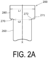
- the stepped cup body 200 has two cylindrical portions 260 and 280, one with a small diameter and the other with a large diameter, connected by a step portion 270, as illustrated in FIG. 2A .
- the small-diameter cylindrical portion 260 has a bottomed cylindrical shape, and the large-diameter cylindrical portion 280 is contiguous to an upper end of the small-diameter cylindrical portion 260 via the step portion 270 and is open on an upper face side.
- An inner diameter of the small-diameter cylindrical portion 260 is equal to the minimum inner diameter of the tapered portion 111 of the body portion 110 of the container 100 desired.
- An inner diameter of the large-diameter cylindrical portion 280 is equal to the maximum inner diameter of the tapered portion 111 of the body portion 110 of the container 100 desired.
- Heights of the small-diameter cylindrical portion 260 and the large-diameter cylindrical portion 280 in a direction of a cylindrical axis X may be the same as or different from each other.
- the step portion 270 is provided over the entire circumference of the stepped cup body 200 and has a step face 271 with an angle of approximately 0° to a horizontal plane perpendicular to the direction of the cylindrical axis X (i.e., parallel to the horizontal plane).
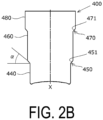
- the stepped cup body may have, as a step face, an inclined face with an angle ⁇ of more than 0° and 60° or less to the horizontal plane perpendicular to the direction of the cylindrical axis X.
- a stepped cup body 400 has three cylindrical portions 440, 460, and 480 of a small diameter, medium diameter, and large diameter, respectively, connected by two step portions 450 and 470 spaced in a height direction.
- the smallest diameter cylindrical portion 440 has a bottomed cylindrical shape
- the medium-diameter cylindrical portion 460 is contiguous to an upper end of the small-diameter cylindrical portion 440 via the step portion 450
- the large-diameter cylindrical portion 480 is contiguous to an upper end of the medium-diameter cylindrical portion 460 via the step portion 470 and is open on an upper face side.
- both step faces 451 and 471 of the two steps 450 and 470, respectively, are inclined faces inclined at an angle ⁇ radially inward and downward in the direction of the cylindrical axis X.
- An inner diameter of the small-diameter cylindrical portion 440 is equal to the minimum inner diameter of the tapered portion 111 of the body portion 110 of the container 100 desired.
- An inner diameter of the large-diameter cylindrical portion 480 is equal to the maximum inner diameter of the tapered portion 111 of the body portion 110 of the container 100 desired.
- the number of step portions of the stepped cup body 200 may be one as in the example in FIG. 2A (step portion 270), or two or more as in the example in FIG. 2B (step portions 450 and 470).
- a height position at which the step portion 270 (step portions 450 and 470) is formed is not limited to the position illustrated in FIG. 2A or 2B and can be determined as appropriate.
- the stretch forming step is performed at least once, and may be repeated a plurality of times.
- the number of repetitions of the stretch forming step varies depending on the size of the container 100 desired, the body taper angle, and the thickness of the sheet metal from which the stepped cup body 200 is formed, and is preferably from 2 to 10 times, more preferably from 2 to 5 times, still more preferably from 2 to 4 times, and particularly preferably 3 times.
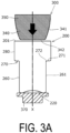
- a manufacturing apparatus in the stretch forming step, includes a forming die including a diameter expanding punch 300 having a tapered pressing portion 340 with a diameter larger than the inner diameter of the small-diameter cylindrical portion 260 and an outer holding tool (not illustrated) having an inner face shape that matches an outer peripheral face (tapered face 341) of the tapered pressing portion 340 of the diameter expanding punch 300 with a peripheral wall 261 of the small-diameter cylindrical portion 260 interposed therebetween.
- the diameter expanding punch 300 has, for example, a cylindrical portion 350 having a right circular cylindrical shape that is contiguous to an upper portion of the tapered pressing portion 340.
- the outer peripheral face of the tapered pressing portion 340 is the tapered face 341 with the same taper angle over the entire circumference that serves as a working face for diameter expansion.
- the taper angle of the tapered face 341 is set to match the desired body taper angle of the tapered portion 111 of the container 100, which is 5° in this embodiment.
- the tapered face 341 may be convex or concave so as to match the body taper angle of the tapered portion 111 of the container 100 desired.
- the maximum outer diameter of the diameter expanding punch 300 is smaller than the inner diameter of the large-diameter cylindrical portion 280.
- the diameter expanding punch 300 has an outer contour shape such that the diameter expanding punch 300 can be loosely inserted into the large-diameter cylindrical portion 280, that is, a slight gap exists between the inner face of the large-diameter cylindrical portion 280 and the outer peripheral face of the cylindrical portion 350 of the diameter expanding punch 300.
- the diameter expanding punch 300 can be reciprocated with a predetermined stroke length by a drive mechanism (not illustrated).
- the apparatus for manufacturing a container according to the present invention includes a plurality of stretch forming dies with the diameter expanding punches 300 having the tapered pressing portions 340 with different outer diameters from each other.
- the diameter expanding punches 300 having the tapered pressing portions 340 with different outer diameters from each other are used.
- the maximum outer diameters of the tapered pressing portions 340 of the diameter expanding punches 300 used for the first, second, ..., nth stretch forming steps are d1, d2, ..., dn, respectively, d1 > d2 > ... > dn.
- taper angles of the tapered faces 341 of the tapered pressing portions 340 of the diameter expanding punches 300 used in the individual stretch forming steps are substantially the same.
- the minimum outer diameter of the tapered pressing portion 340 of the diameter expanding punch 300 used in the (n-1)th stretch forming step is smaller than the maximum outer diameter of the tapered pressing portion 340 of the diameter expanding punch 300 used in the nth stretch forming step following the (n-1)th stretch forming step.
- the lengths of the tapered pressing portions 340 of the diameter expanding punches 300 used in the individual stretch forming steps are substantially the same, and a specific length is determined by the height of the tapered portion 111 in the body portion 110 of the container 100 desired and the number of repetitions of the stretch forming step.
- the taper angles and the axial lengths of the tapered faces 341 of the tapered pressing portions 340 in the individual diameter expanding punches 300 are not limited to the same dimensions and need only be set to dimensions suitable for the specific cup shape of the container 100 desired, respectively.
- the tapered face 341 may be curved.
- the minimum outer diameters and the maximum outer diameters of the tapered pressing portions 340 of the individual diameter expanding punches 300 also need only be set to dimensions suitable for the specific cup shape of the container 100 desired, respectively.
- the stepped cup body 200 is first placed on a base 370 with an open end portion 201 side facing the base 370 side, then the diameter expanding punch 300 is coaxially placed in such a posture that the tapered face 341 narrows toward the open end portion 201 of the stepped cup body 200 (inverted truncated cone shape). Subsequently, as illustrated in FIG. 3B , the diameter expanding punch 300 is relatively moved along the direction of the cylindrical axis X from the side of the open end portion 201 of the stepped cup body 200 to a predetermined position (moved downward in FIG.
- the tapered face 341 of the tapered pressing portion 340 begins to come into contact with a corner portion 272 of the step portion 270, and the step portion 270 and part of the peripheral wall 261 are expanded in an inverted truncated cone shape, and the step portion 270 disappears.
- an upper end of the tapered pressing portion 340 of the diameter expanding punch 300 is moved to a level position to be the upper end of the tapered portion 111, the movement of the diameter expanding punch 300 is stopped, and as illustrated in FIG.
- a new bent portion 262 is formed in the small-diameter cylindrical portion 260 at a position corresponding to a lower end of the moved tapered pressing portion 340, and a tapered cylindrical portion 251 having a tapered shape corresponding to the tapered face 341 of the tapered pressing portion 340 of the diameter expanding punch 300 and the outer holding tool is formed. Further, a part of the stepped cup body 200 that was in contact with the cylindrical portion 350 of the diameter expanding punch 300 on the open end portion 201 side, or a part of the stepped cup body 200 that was not in contact with the diameter expanding punch 300, becomes the upper side portion 113 of the container 100.
- a new tapered cylindrical portion is formed in a state in which the bent portion 262 formed in the preceding stretch forming step is expanded to overlap or to be adjacent to the tapered cylindrical portion 251 formed in the preceding stretch forming step on the bottom portion 220 side so as to be smoothly connected to each other in a tapered shape.
- a plurality of tapered cylindrical portions 251 are smoothly connected to form the tapered portion 111, thereby obtaining the container 100 with the body portion 110 having the tapered portion 111 formed with a uniform outward expanding angle.
- the stretch ratio in the stretch forming step varies depending on the body taper angle of the tapered portion 111 of the container 100 to be manufactured, and is preferably from 2% to 15%, more preferably from 3% to 7%, and 5% in this embodiment at a height position corresponding to the top part of the tapered portion 111.
- the stretch ratio in the stretch forming step is, preferably from 1% to 10%, more preferably from 2% to 5%, and 3% in this embodiment.
- the stretch ratio at the height position corresponding to the top part of the tapered portion 111 is defined by (A1 - L1)/L1 ⁇ 100(%) (Expression (1)), where L1 is a diameter at the height position to be the top part of the tapered portion 111 in the stepped cup body 200 prior to the first stretch forming step (can to be processed), and A1 is a diameter at the top part of tapered portion 111 of the container 100 after the last (nth) stretch forming step (maximum diameter of the tapered portion 111).
- the stretch ratio at the height position corresponding to just below the step portion 270 of the stepped cup body 200 is defined by (A2 - L2)/L2 x 100(%) (Expression (2)), where L2 is a diameter at the top part of the small-diameter cylindrical portion 260 in the stepped cup body 200 prior to the first stretch forming step (can to be processed), and A2 is a diameter at the height position of the container 100, which was the top part of the small-diameter cylindrical portion 260, after the last (nth) stretch forming step.
- the stretch ratio in the stretch forming step be in a range of 2% to 7% at any height position of the stepped cup body 200.
- the stretch ratio is excessive, there is a risk that the stress applied to the metal material due to processing will exceed the limit of plastic deformation and break the tapered portion 111 of the container 100.
- a sheet metal similar to well-known two-piece beverage cans made of an aluminum alloy, a sheet metal of an aluminum alloy having a thickness of from 0.20 mm to 0.35 mm laminated with polyethylene terephthalate (PET) films having a thickness of approximately 0.01 mm on both sides is used.
- PET polyethylene terephthalate
- the thickness of the bottom portion in which the thickness of the material is substantially maintained is from 0.20 mm to 0.35 mm, and the thickness of the body portion 110 in the height range of 50 ⁇ 10%, when the total height of the container is 100%, has a thickness of from 0.10 to 0.22 mm.
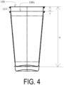
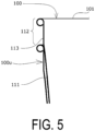
- a projecting portion 112 projects from an upper end side of the container 100u below, and a projecting height T of the projecting portion 112 is determined by a height of the upper side portion 113, a height of the lower side portion 114, a shape of the bottom portion 120, and the like.
- the projecting height T is 8.0 mm
- the ratio of the height T of the projecting portion to a height H of the container 100 is 7.1%.
- the upper side portion 113 and the lower side portion 114 may be formed so as to expand outward at angles different from the angle of the tapered portion 111, or only one of them may be provided, or neither may be provided.
- the upper side portion 113 and the lower side portion 114 may be tapered oppositely to the tapered portion 111 so as to narrow inward.
- a bead which is an independent contact portion that projects to an inner face side of the body portion 110 and comes into contact with an outer face of the container stacked above, may be provided, thereby preventing the outer face of the body portion 110 of the container 100 placed above and the inner face of the body portion 110 of the container 100u placed below from coming into close contact with each other.
- the bead may be of any shape, direction, quantity, and location, may project to the inner face side, may project to the outer face side, or a mixture of the inner and outer faces may exist.
- the projecting portion may be a point or a face projecting from the tapered portion 111 rather than the bead shape.
- the container 100 may be used as a can filled with a beverage or the like and subsequently provided with a lid member.
- the lid member may be any stay-on-tab lid made of metal, a sheet made of a layered body, a screw lid, or the like.
- the lid member In a case in which the lid member is wound and tightened on the upper end of the body portion as a stay-on-tab lid, the upper end of the body portion of the container need only be subjected to trimming for the winding and tightening and subsequently subjected to flanging that forms a face portion.
- the lid member is bonded by heat or other means to the upper end of the body portion as a sheet composed of a layered body
- the upper end of the body portion of the container may be imparted with a shape that includes a face portion to ensure the bonding area.
- the sheet composed of a layered body include aluminum foil, paper, a resin film, and a laminate material obtained by layering two or more of these, and a thermal adhesive layer (heat-sealed layer) may be further layered.
- a layer composed of an adhesive such as a known sealant film, a lacquer type adhesive, an easy peel adhesive, or a hot melt adhesive can be employed.
- the projecting portion 112 of the upper side portion 113 or the like of the upper end of the body portion of the container may include screw threads, or a lid member with a spout including separate screw threads may be wound and tightened around the upper end of the body portion of the container to screw-fix the screw lid.
- a container in the method for manufacturing a container according to the present invention, not only the container in which the tapered portion of the body portion is formed into the shape that expands outward at the body taper angle of from 2° to 15° at any location, but also following containers can be manufactured: a container partially having a portion outside the range of from 2° to 15° similar to the upper side portion and the lower side portion in the present embodiment, a curved container in which the outward expanding angle of the body portion gradually changes in a cross-sectional view, and a container having a plurality of stepped portions on the body portion, and a container having a body portion with a combination of linear expanding, curved expanding, stepped portions, and the like.
- the body portion 110 it is not limited to forming the body portion 110 by dividing the body portion 110 in the height direction in the individual stretch forming steps as in the first embodiment, but the body portion 110 may be formed to gradually expand in the lateral direction in the individual stretch forming steps by dividing the desired final body taper angle.
- a method for manufacturing a container according to a second embodiment will be described below.
- diameter expanding punches are used that include tapered pressing portions having inverted truncated cone shapes that have lengths (axial lengths of the tapered pressing portions) equivalent to a height of the tapered portion 111 of the body portion 110 of the container 100 desired, and that have tapered faces with different taper angles from each other, and that have different outer diameters from each other.
- the taper angles of the diameter expanding punches used for the first, second, ..., nth stretch forming steps are ⁇ 1, ⁇ 2, ..., ⁇ n, respectively, ⁇ 1 ⁇ ⁇ 2 ⁇ ... ⁇ ⁇ n is satisfied.
- An angle difference between the taper angle ⁇ (n-1) of the diameter expanding punch used in the (n-1) stretch forming step and the taper angle ⁇ n of the diameter expanding punch used in the subsequent nth stretch forming step is, for example, approximately 2.5°.
- the taper angle of the diameter expanding punch used in the first stretch forming step is 2.5°
- the taper angle of the diameter expanding punch used in the second (last) stretch forming step is 5°.
- a stepped cup body 500 having one step portion 570 with an inclined step face 571 is placed on a base (not illustrated) with an open end portion 501 side facing the base 370 side, then the diameter expanding punch (not illustrated) is coaxially placed in such a posture that the tapered face narrows toward the open end portion 501 of the stepped cup body 500 (inverted truncated cone shape). Then, the diameter expanding punch is relatively moved along the direction of the cylindrical axis X from the open end portion 501 side of the stepped cup body 500 (moved downward in FIG.
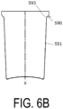
- the tapered face of the tapered pressing portion of the diameter expanding punch begins to come into contact with a corner portion 573 on the inner side of the step portion 570, part of the corner portion 573 on the inner side of the step portion 570 is expanded in diameter and disappears as the diameter expanding punch moves, a new step portion 590 is formed by a remaining corner portion 593, and a tapered cylindrical portion 551 is formed by being expanded in an inverted truncated cone shape that matches a taper angle (taper angle ⁇ 1) of the tapered face of the diameter expanding punch used.
- a subsequent stretch forming step by performing the similar operation using a diameter expanding punch having a tapered pressing portion with a large tapered angle (taper angle ⁇ 2), as illustrated in FIG. 6C , the corner portion 593 of the step portion 590, which is part of the corner portion remaining in the preceding stretch forming step, is expanded and disappears, and the tapered cylindrical portion 551 formed in the preceding stretch forming step is further expanded in diameter to form a new tapered cylindrical portion 552 (the body portion 110) having a larger taper angle (taper angle ⁇ 2) matching the taper angle of the tapered face of the diameter expanding punch used (taper angle ⁇ 2).
- the body portion 110 is gradually expanded laterally in diameter to form the tapered portion 111, thereby obtaining the container 100 with the body portion 110 having the tapered portion 111 having a tapered shape with a uniform outward expanding angle.
Landscapes
- Engineering & Computer Science (AREA)
- Mechanical Engineering (AREA)
- Containers Having Bodies Formed In One Piece (AREA)
- Shaping Metal By Deep-Drawing, Or The Like (AREA)
- Making Paper Articles (AREA)
- Supplying Of Containers To The Packaging Station (AREA)
- Table Devices Or Equipment (AREA)
Abstract
Description
- The present invention relates to a method for manufacturing a container made of metal, open on an upper face side, and including a bottom portion and a body portion and to an apparatus for manufacturing a container.
- In recent years, in order to conserve resources, reduce waste, and the like, there has been a growing demand for a lightweight, inexpensive, and easily recyclable container that can be used as an alternative to a container made of paper, plastic, or the like.
- It is conceivable to adapt a well-known container made of metal and open on an upper face side, which is used as tableware or as a container for filling beverages, food, or the like (refer to Patent Document 1, etc.).
- As known containers open on an upper face side, containers made of metal that are washed and used many times, such as those used for tableware, are well known. However, because of the need to increase durability in consideration of long-term use, a certain plate thickness is necessary to increase strength, resulting in higher material costs and molding costs and a heavier weight, thus making the container a highly problematic alternative to containers made of paper, plastic, or the like.
- In recent years, the recycling capabilities for metal can containers have improved, and using metal containers made of thin materials, such as the one in Patent Document 1, can now reduce material costs and molding costs and has a lighter weight, while saving resources and reducing waste, even if used only once as tableware.
- Nevertheless, there is a problem in that a container made of metal and having an open upper face side is not suitable in shape or structure for being stored and transported while empty and being used by a user while open.
- Further, the growing global awareness of the need to prevent environmental pollution, such as the ongoing pollution of the oceans caused by plastics, has led to a demand for containers made of a material that can be easily recovered for recycling.
- On the other hand, manufacturing a container made of metal and open on an upper face side requires a technique for forming a body portion into a tapered shape as disclosed in Patent Document 2 and the like. However, the conventional method for manufacturing beverage cans is to form a tapered shape only in a partial range in a height direction of the body portion, such as a neck and chime, and no method has been established to form a smooth tapered shape over a wide height range of approximately from 70% to 90% of the body portion of the container.
-
- Patent Document 1:
JP 2003-128060 A - Patent Document 2:
JP 2006-224113 A - An object of the present invention is to solve the problems described above, and to provide a method for manufacturing a container and an apparatus for manufacturing a container, by which it is possible to easily manufacture a container having a body portion with a shape that expands outward toward an upper face side of the body portion.
- A method for manufacturing a container according to the present invention is a method for manufacturing a container made of metal, including a bottom portion and a body portion, being open on an upper face side, and having a shape in which the body portion expands outward toward the upper face side. The problem is solved by including a stretch forming step of expanding a diameter of a stepped cup body made of metal and having a small-diameter cylindrical portion having a bottomed cylindrical shape and a large-diameter cylindrical portion with an opening on an upper face side and contiguous to an upper end of the small-diameter cylindrical portion via a step portion by operating a diameter expanding punch having a tapered pressing portion that is smaller in diameter than an inner diameter of the large-diameter cylindrical portion and larger in diameter than an inner diameter of the small-diameter cylindrical portion of the stepped cup body along a cylindrical axis direction from an opening side of the large-diameter cylindrical portion, and performing the stretch forming step at least once.
- An apparatus for manufacturing a container according to the present invention is an apparatus for manufacturing a container made of metal, including a bottom portion and a body portion, being open on an upper face side, and having a shape in which the body portion expands outward toward the upper face side. The apparatus includes at least one stretch forming die, each stretch forming die including a diameter expanding punch having a tapered pressing portion that is configured to expand a diameter of a stepped cup body made of metal and having a small-diameter cylindrical portion having a bottomed cylindrical shape and a large-diameter cylindrical portion with an opening on an upper face side and contiguous to an upper end of the small-diameter cylindrical portion via a step portion by pressing along a cylindrical axis direction from an opening side of the large-diameter cylindrical portion and that is smaller in diameter than an inner diameter of the large-diameter cylindrical portion and larger in diameter than an inner diameter of the small-diameter cylindrical portion of the stepped cup body.
- According to the method for manufacturing a container according to claim 1 and the apparatus for manufacturing a container according to claim 11, by performing the stretch forming step of expanding the diameter of the stepped cup body made of metal and having the bottomed cylindrical shape at least once, the diameter of the stepped cup body can be expanded without causing damage to the cup body, such as wrinkles or cracks. Thus, even when a wide height range of the body portion of the container is tapered, it is possible to easily manufacture a container with a desired smooth tapered body portion that expands outward toward the upper face side and is made of metal and easily recycled. In addition, since it is not necessary to operate the diameter expanding punch with a long stroke, the manufacturing facility can be downsized, and the manufacturing process can be sped up.
- According to the method for manufacturing a container according to claim 2 and the apparatus for manufacturing a container according to claim 12, by repeating the stretch forming step a plurality of times, the body portion of the container can be reliably formed into the tapered shape over the wide height range. By repeating the stretch forming step from 2 to 10 times, the body portion of the container can be more reliably formed into the tapered shape over the wide height range.
- According to the method for manufacturing a container according to claim 4 and the apparatus for manufacturing a container according to claim 14, since an angle of the step portion of the stepped cup body to a plane perpendicular to an axial direction of the stepped cup body (horizontal plane) is from 0° to 60°, the stepped cup body can be easily formed into the tapered shape over the wide height range while suppressing the occurrence of wrinkles or the like.
- According to the method for manufacturing a container according to claim 5 and the apparatus for manufacturing a container according to claim 15, a diameter of a tapered pressing portion of a diameter expanding punch used in a stretch forming step performed earlier and a diameter of a tapered pressing portion of a diameter expanding punch used in a stretch forming step performed subsequently are different from each other, so that the body portion of the container can be reliably formed into a tapered shape over a wide height range.
- According to the method for manufacturing a container according to claim 6, by forming the body portion so that a line connecting an outer peripheral face at 10% height and an outer peripheral face at 90% height from a lowermost portion expands outward at an angle of from 2° to 15°, preferably from 3° to 10° (body taper angle) when a total height of the container is 100%, the container can be manufactured with a shape that has high strength, is easy to stack, and is easy for a user to hold, while suppressing toppling when the center of gravity is raised by containing beverages or the like. Containers formed with the body taper angle of more than 15° increase the distance between adjacent containers when arranged in upright postures, resulting in inefficient storage. On the other hand, containers formed with the body taper angle of less than 2° are difficult to separate when stacked containers are separated because the stacked containers stick to each other or the like.
- Further, according to the container manufactured in this way, when the two containers are stacked, a projecting portion of the container placed above projecting from the container placed below has a height of 20 mm or less from an upper end of the container placed below, so that the height of a plurality of stacked containers can be reduced.
- Furthermore, when transporting and transferring containers to a facility for filling beverages, food, or the like, a lid attachment facility, or the like, the containers can be transported and transferred in a stacked state, thereby improving efficiency in cans manufacturing, or the like by filling beverages, food, or the like, and then sealing the filled cans.
- According to the configuration described in claim 7, by making the thickness of the bottom portion 0.20 mm or greater, the center of gravity can be lowered. Thus, the containers can be manufactured with good self-standing stability.
- Further, the thickness of the bottom portion is 0.35 mm or less, and the thickness of the body portion is from 0.10 to 0.22 mm in a height range of 50 ± 10% when the total height of the container is 100%. This makes it possible to reduce the material costs and the forming costs and lighten the weight, and obtain a container that is formed into a shape in which a line connecting an outer peripheral face at 10% height and an outer peripheral face at 90% height from the lowermost portion expands upward and outward at an angle of from 3° to 10° when the total height of the container is 100% (a more suitable shape).
- According to the configuration described in claim 8, by setting a ratio of the projecting portion to a height of the container to be from 4% to 15%, the volume can be reduced while ensuring ease of separation by preventing the containers from sticking or the like when a plurality of containers are stacked, thereby improving efficiency when storing and transporting empty containers. The ratio of the above-described projecting portion to the height of the container is preferably 5% to 9%.
- According to the configuration described in
claim 10, by making the body portion have a contact portion that prevents the body portion from coming into close contact with another container by reducing the contact area with the other container, it is possible to obtain containers in which the body portions are reliably prevented from coming into close contact with each other when a plurality of containers are stacked, and that are further improved in ease of separation because the portions other than the contact portion are non-contact and circulation of air between the containers can be ensured when individually separating the stacked plurality of containers. -
-
FIG. 1 is a side view of a container manufactured by a method for manufacturing a container according to an embodiment of the present invention. -
FIG. 2A is a side view of a stepped cup body used in a method for manufacturing a container of the present invention. -
FIG. 2B is a side view of another stepped cup body used in the method for manufacturing a container of the present invention. -
FIG. 3A is a schematic diagram for describing a method for manufacturing a container according to the embodiment of the present invention. -
FIG. 3B is a schematic diagram for describing the method for manufacturing the container illustrated inFIG. 3A according to the embodiment. -
FIG. 3C is a schematic diagram for describing the method for manufacturing the container illustrated inFIG. 3A according to the embodiment. -
FIG. 4 is a side view of two containers, one being illustrated inFIG. 1 , stacked on top of each other. -
FIG. 5 is a partially enlarged cross-sectional view of the two containers stacked on top of each other illustrated inFIG. 4 . -
FIG. 6A is a schematic diagram for describing a method for manufacturing a container according to another embodiment of the present invention. -
FIG. 6B is a schematic diagram for describing the method for manufacturing the container illustrated inFIG. 6A according to the other embodiment. -
FIG. 6C is a schematic diagram for describing the method for manufacturing the container illustrated inFIG. 6A according to the other embodiment. - A container manufactured by a method for manufacturing a container according to the present invention will be described below.
- As illustrated in
FIG. 1 , the container manufactured by the method for manufacturing a container according to the present invention is acontainer 100 that includes abottom portion 120 and abody portion 110, is made of metal, has anupper opening 101 open on an upper face side, and can be replaced in shape with a well-known paper cup or plastic cup. - The
body portion 110 of thecontainer 100 has a taperedportion 111 having an inverted truncated cone shape (tapered shape) that expands outward toward an upper side (upper opening 101 side), anupper side portion 113 that is continuous between thetapered portion 111 and theupper opening 101, and alower side portion 114 that is continuous between thetapered portion 111 and thebottom portion 120. The taperedportion 111 of thebody portion 110 has, for example, a linear and uniform tapered shape in a cross-sectional view, and an angle θ thereof is 5°. - Further, the
upper side portion 113 and thelower side portion 114 do not expand outward and have an approximately cylindrical shape. - The tapered
portion 111 of thecontainer 100 is formed with a uniform outward expanding angle from 10% height to 90% height from a horizontal plane with a total height of the container being 100%, for example, when thecontainer 100 is placed on the horizontal plane with thebottom portion 120 facing downward, so the outward expanding angle of a line connecting an outer peripheral face at the 10% height and an outer peripheral face at the 90% height from the lowermost portion (body taper angle), with a total height of the container being 100% is approximately 5°, which is substantially the same as θ. - In the present embodiment, the
bottom portion 120 is formed into a similar shape to that of well-known two-piece beverage cans. - A fringe of the
upper opening 101, that is, the upper end portion of thebody portion 110 is formed into a shape in which a sharp edge thereof does not come into direct contact with a mouth, for example, a curled shape, for use as a cup. - An embodiment (first embodiment) of the method for manufacturing a container according to the present invention will be described below.
- The
container 100 includes a stepped cup body forming step of forming a metal sheet (blank) into a stepped shape having a bottom and two cylindrical portions with a large diameter and a small diameter to obtain a steppedcup body 200, and a stretch forming step of forming atapered portion 111 that expands outward toward anupper opening 101 side by stretching the small-diameter cylindrical portion of the obtained steppedcup body 200 so that the diameter expands toward anopen end portion 201 side. After the stretch forming step, a curl forming step of curling an upper end portion of thebody portion 110 into a round shape is performed. Note that the curl forming step may be performed before the stretch forming step or in the middle of a plurality of stretch forming steps. - The stepped
cup body 200 has twocylindrical portions step portion 270, as illustrated inFIG. 2A . The small-diametercylindrical portion 260 has a bottomed cylindrical shape, and the large-diametercylindrical portion 280 is contiguous to an upper end of the small-diametercylindrical portion 260 via thestep portion 270 and is open on an upper face side. - An inner diameter of the small-diameter
cylindrical portion 260 is equal to the minimum inner diameter of the taperedportion 111 of thebody portion 110 of thecontainer 100 desired. An inner diameter of the large-diametercylindrical portion 280 is equal to the maximum inner diameter of the taperedportion 111 of thebody portion 110 of thecontainer 100 desired. - Heights of the small-diameter
cylindrical portion 260 and the large-diametercylindrical portion 280 in a direction of a cylindrical axis X may be the same as or different from each other. - The
step portion 270 is provided over the entire circumference of the steppedcup body 200 and has astep face 271 with an angle of approximately 0° to a horizontal plane perpendicular to the direction of the cylindrical axis X (i.e., parallel to the horizontal plane). - The stepped cup body may have, as a step face, an inclined face with an angle α of more than 0° and 60° or less to the horizontal plane perpendicular to the direction of the cylindrical axis X. Specifically, as illustrated in
FIG. 2B , a steppedcup body 400 has threecylindrical portions step portions cylindrical portion 440 has a bottomed cylindrical shape, and the medium-diametercylindrical portion 460 is contiguous to an upper end of the small-diametercylindrical portion 440 via thestep portion 450, and the large-diametercylindrical portion 480 is contiguous to an upper end of the medium-diametercylindrical portion 460 via thestep portion 470 and is open on an upper face side. Then, both step faces 451 and 471 of the twosteps cylindrical portion 440 is equal to the minimum inner diameter of the taperedportion 111 of thebody portion 110 of thecontainer 100 desired. An inner diameter of the large-diametercylindrical portion 480 is equal to the maximum inner diameter of the taperedportion 111 of thebody portion 110 of thecontainer 100 desired. - The number of step portions of the stepped
cup body 200 may be one as in the example inFIG. 2A (step portion 270), or two or more as in the example inFIG. 2B (step portions 450 and 470). - Further, a height position at which the step portion 270 (
step portions 450 and 470) is formed is not limited to the position illustrated inFIG. 2A or2B and can be determined as appropriate. - In the present invention, the stretch forming step is performed at least once, and may be repeated a plurality of times.
- When the stretch forming step is performed a plurality of times, the number of repetitions of the stretch forming step varies depending on the size of the
container 100 desired, the body taper angle, and the thickness of the sheet metal from which the steppedcup body 200 is formed, and is preferably from 2 to 10 times, more preferably from 2 to 5 times, still more preferably from 2 to 4 times, and particularly preferably 3 times. - When the number of repetitions of the stretch forming step is excessive, an increase in the number of steps may increase the manufacturing load and manufacturing costs, and a large influence of forming heat may cause non-negligible variations in finished dimensions, resulting in low yields and low productivity. On the other hand, when the number of repetitions of the stretch forming step is not sufficient, manufacturing a
container 100 having a large size or a large body taper angle requires a large stretch ratio in one stretch forming step, which may cause damage such as breakage in thebody portion 110. - In the stretch forming step, a manufacturing apparatus is used that includes a forming die including a
diameter expanding punch 300 having a taperedpressing portion 340 with a diameter larger than the inner diameter of the small-diametercylindrical portion 260 and an outer holding tool (not illustrated) having an inner face shape that matches an outer peripheral face (tapered face 341) of the taperedpressing portion 340 of thediameter expanding punch 300 with aperipheral wall 261 of the small-diametercylindrical portion 260 interposed therebetween. - The
diameter expanding punch 300 has, for example, acylindrical portion 350 having a right circular cylindrical shape that is contiguous to an upper portion of the taperedpressing portion 340. The outer peripheral face of the taperedpressing portion 340 is the taperedface 341 with the same taper angle over the entire circumference that serves as a working face for diameter expansion. The taper angle of the taperedface 341 is set to match the desired body taper angle of the taperedportion 111 of thecontainer 100, which is 5° in this embodiment. Thetapered face 341 may be convex or concave so as to match the body taper angle of the taperedportion 111 of thecontainer 100 desired. - The maximum outer diameter of the
diameter expanding punch 300 is smaller than the inner diameter of the large-diametercylindrical portion 280. Specifically, thediameter expanding punch 300 has an outer contour shape such that thediameter expanding punch 300 can be loosely inserted into the large-diametercylindrical portion 280, that is, a slight gap exists between the inner face of the large-diametercylindrical portion 280 and the outer peripheral face of thecylindrical portion 350 of thediameter expanding punch 300. - The
diameter expanding punch 300 can be reciprocated with a predetermined stroke length by a drive mechanism (not illustrated). - The apparatus for manufacturing a container according to the present invention includes a plurality of stretch forming dies with the
diameter expanding punches 300 having the taperedpressing portions 340 with different outer diameters from each other. In the individual stretch forming steps according to the method for manufacturing a container of the first embodiment, thediameter expanding punches 300 having the taperedpressing portions 340 with different outer diameters from each other are used. When the maximum outer diameters of the taperedpressing portions 340 of thediameter expanding punches 300 used for the first, second, ..., nth stretch forming steps are d1, d2, ..., dn, respectively, d1 > d2 > ... > dn. - The taper angles of the tapered faces 341 of the tapered
pressing portions 340 of thediameter expanding punches 300 used in the individual stretch forming steps are substantially the same. - The minimum outer diameter of the tapered
pressing portion 340 of thediameter expanding punch 300 used in the (n-1)th stretch forming step is smaller than the maximum outer diameter of the taperedpressing portion 340 of thediameter expanding punch 300 used in the nth stretch forming step following the (n-1)th stretch forming step. - The lengths of the tapered
pressing portions 340 of thediameter expanding punches 300 used in the individual stretch forming steps (axial lengths of the tapered pressing portions 340) are substantially the same, and a specific length is determined by the height of the taperedportion 111 in thebody portion 110 of thecontainer 100 desired and the number of repetitions of the stretch forming step. - The taper angles and the axial lengths of the tapered faces 341 of the tapered
pressing portions 340 in the individualdiameter expanding punches 300 are not limited to the same dimensions and need only be set to dimensions suitable for the specific cup shape of thecontainer 100 desired, respectively. For example, the taperedface 341 may be curved. The minimum outer diameters and the maximum outer diameters of the taperedpressing portions 340 of the individualdiameter expanding punches 300 also need only be set to dimensions suitable for the specific cup shape of thecontainer 100 desired, respectively. - In the stretch forming step according to the method for manufacturing a container of the first embodiment, as illustrated in
FIG. 3A , the steppedcup body 200 is first placed on a base 370 with anopen end portion 201 side facing the base 370 side, then thediameter expanding punch 300 is coaxially placed in such a posture that thetapered face 341 narrows toward theopen end portion 201 of the stepped cup body 200 (inverted truncated cone shape). Subsequently, as illustrated inFIG. 3B , thediameter expanding punch 300 is relatively moved along the direction of the cylindrical axis X from the side of theopen end portion 201 of the steppedcup body 200 to a predetermined position (moved downward inFIG. 3B ) with the outer holding tool (not illustrated) arranged outside the steppedcup body 200. When thediameter expanding punch 300 is moved, the taperedface 341 of the taperedpressing portion 340 begins to come into contact with acorner portion 272 of thestep portion 270, and thestep portion 270 and part of theperipheral wall 261 are expanded in an inverted truncated cone shape, and thestep portion 270 disappears. Then, when an upper end of the taperedpressing portion 340 of thediameter expanding punch 300 is moved to a level position to be the upper end of the taperedportion 111, the movement of thediameter expanding punch 300 is stopped, and as illustrated inFIG. 3C , a newbent portion 262 is formed in the small-diametercylindrical portion 260 at a position corresponding to a lower end of the moved taperedpressing portion 340, and a taperedcylindrical portion 251 having a tapered shape corresponding to the taperedface 341 of the taperedpressing portion 340 of thediameter expanding punch 300 and the outer holding tool is formed. Further, a part of the steppedcup body 200 that was in contact with thecylindrical portion 350 of thediameter expanding punch 300 on theopen end portion 201 side, or a part of the steppedcup body 200 that was not in contact with thediameter expanding punch 300, becomes theupper side portion 113 of thecontainer 100. - In the subsequent stretch forming step, by performing the similar operation using a diameter expanding punch having a tapered pressing portion with a smaller diameter, a new tapered cylindrical portion is formed in a state in which the
bent portion 262 formed in the preceding stretch forming step is expanded to overlap or to be adjacent to the taperedcylindrical portion 251 formed in the preceding stretch forming step on thebottom portion 220 side so as to be smoothly connected to each other in a tapered shape. - A lower part of the small-diameter
cylindrical portion 260 of the steppedcup body 200 that remains unprocessed due to non-contact with thediameter expanding punch 300 in the final stretch forming step becomes thelower side portion 114 of thecontainer 100. - By repeating the above-described stretch forming step, a plurality of tapered
cylindrical portions 251 are smoothly connected to form the taperedportion 111, thereby obtaining thecontainer 100 with thebody portion 110 having the taperedportion 111 formed with a uniform outward expanding angle. - The stretch ratio in the stretch forming step varies depending on the body taper angle of the tapered
portion 111 of thecontainer 100 to be manufactured, and is preferably from 2% to 15%, more preferably from 3% to 7%, and 5% in this embodiment at a height position corresponding to the top part of the taperedportion 111. At a height position corresponding to just below thestep portion 270 of the stepped cup body 200 (the top part of the small-diameter cylindrical portion 260), the stretch ratio in the stretch forming step is, preferably from 1% to 10%, more preferably from 2% to 5%, and 3% in this embodiment. - The stretch ratio at the height position corresponding to the top part of the tapered
portion 111 is defined by (A1 - L1)/L1 × 100(%) (Expression (1)), where L1 is a diameter at the height position to be the top part of the taperedportion 111 in the steppedcup body 200 prior to the first stretch forming step (can to be processed), and A1 is a diameter at the top part of taperedportion 111 of thecontainer 100 after the last (nth) stretch forming step (maximum diameter of the tapered portion 111). The stretch ratio at the height position corresponding to just below thestep portion 270 of the steppedcup body 200 is defined by (A2 - L2)/L2 x 100(%) (Expression (2)), where L2 is a diameter at the top part of the small-diametercylindrical portion 260 in the steppedcup body 200 prior to the first stretch forming step (can to be processed), and A2 is a diameter at the height position of thecontainer 100, which was the top part of the small-diametercylindrical portion 260, after the last (nth) stretch forming step. - It is preferable that the stretch ratio in the stretch forming step be in a range of 2% to 7% at any height position of the stepped
cup body 200. - The smaller the stretch ratio, the smaller the degree of plastic deformation, and thus the tapered
portion 111 having a desired tapered shape can be obtained without damage. When the stretch ratio is excessive, there is a risk that the stress applied to the metal material due to processing will exceed the limit of plastic deformation and break the taperedportion 111 of thecontainer 100. - As a sheet metal, similar to well-known two-piece beverage cans made of an aluminum alloy, a sheet metal of an aluminum alloy having a thickness of from 0.20 mm to 0.35 mm laminated with polyethylene terephthalate (PET) films having a thickness of approximately 0.01 mm on both sides is used.
- By using such a sheet metal, after forming the container, the thickness of the bottom portion in which the thickness of the material is substantially maintained is from 0.20 mm to 0.35 mm, and the thickness of the
body portion 110 in the height range of 50 ± 10%, when the total height of the container is 100%, has a thickness of from 0.10 to 0.22 mm. - When the
containers 100 according to the present invention are stacked as illustrated inFIGS. 4 and5 , at least one of the following areas (1) and (2) overlaps in contact: (1) a vicinity of an upper end of the outer face of the taperedportion 111 of thecontainer 100 placed above and a vicinity of an upper end of the inner face of theupper side portion 113 of acontainer 100u placed below, and (2) a vicinity of a lower end of the outer face of thelower side portion 114 of thecontainer 100 placed above and a vicinity of a lower end of the inner face of the taperedportion 111 of thecontainer 100u placed below, and the outer face of the taperedportion 111 of thecontainer 100 placed above and the inner face of the taperedportion 111 of thecontainer 100u placed below do not come into close contact with each other by face. - On an upper end side of the
container 100 above, a projectingportion 112 projects from an upper end of thecontainer 100u below, and a projecting height T of the projectingportion 112 is determined by a height of theupper side portion 113, a height of thelower side portion 114, a shape of thebottom portion 120, and the like. - In the example in
FIG. 4 , the projecting height T is 8.0 mm, and the ratio of the height T of the projecting portion to a height H of thecontainer 100 is 7.1%. - Note that the
upper side portion 113 and thelower side portion 114 may be formed so as to expand outward at angles different from the angle of the taperedportion 111, or only one of them may be provided, or neither may be provided. - Further, the
upper side portion 113 and thelower side portion 114 may be tapered oppositely to the taperedportion 111 so as to narrow inward. - In a case in which the
upper side portion 113 and thelower side portion 114 do not exist, or are extremely small so that when stacked, the outer face of thebottom portion 120 of thecontainer 100 placed above and the inner face of thebottom portion 120 of thecontainer 100u placed below can be in close contact, a bead, which is an independent contact portion that projects to an inner face side of thebody portion 110 and comes into contact with an outer face of the container stacked above, may be provided, thereby preventing the outer face of thebody portion 110 of thecontainer 100 placed above and the inner face of thebody portion 110 of thecontainer 100u placed below from coming into close contact with each other. - The bead may be of any shape, direction, quantity, and location, may project to the inner face side, may project to the outer face side, or a mixture of the inner and outer faces may exist.
- Further, as long as a projecting portion functions as a contact portion, the projecting portion may be a point or a face projecting from the tapered
portion 111 rather than the bead shape. - Further, the
container 100 may be used as a can filled with a beverage or the like and subsequently provided with a lid member. - The lid member may be any stay-on-tab lid made of metal, a sheet made of a layered body, a screw lid, or the like.
- In a case in which the lid member is wound and tightened on the upper end of the body portion as a stay-on-tab lid, the upper end of the body portion of the container need only be subjected to trimming for the winding and tightening and subsequently subjected to flanging that forms a face portion.
- In a case in which the lid member is bonded by heat or other means to the upper end of the body portion as a sheet composed of a layered body, the upper end of the body portion of the container may be imparted with a shape that includes a face portion to ensure the bonding area. Examples of the sheet composed of a layered body include aluminum foil, paper, a resin film, and a laminate material obtained by layering two or more of these, and a thermal adhesive layer (heat-sealed layer) may be further layered. As the thermal adhesive layer, a layer composed of an adhesive such as a known sealant film, a lacquer type adhesive, an easy peel adhesive, or a hot melt adhesive can be employed.
- In a case in which the lid member is screw-fixed to the upper end of the body portion as a screw lid, the projecting
portion 112 of theupper side portion 113 or the like of the upper end of the body portion of the container may include screw threads, or a lid member with a spout including separate screw threads may be wound and tightened around the upper end of the body portion of the container to screw-fix the screw lid. - By matching the projecting
portion 112 to the attachment form of the lid member, it is possible to improve efficiency when storing and transporting the container portion regardless of the type of lid member. - The method for manufacturing a container and the apparatus for manufacturing a container according to the first embodiment of the present invention have been described in detail above, but the present invention is not limited to the embodiment described above, and various changes can be made within the scope of the present invention described in the claims.
- For example, in the method for manufacturing a container according to the present invention, not only the container in which the tapered portion of the body portion is formed into the shape that expands outward at the body taper angle of from 2° to 15° at any location, but also following containers can be manufactured: a container partially having a portion outside the range of from 2° to 15° similar to the upper side portion and the lower side portion in the present embodiment, a curved container in which the outward expanding angle of the body portion gradually changes in a cross-sectional view, and a container having a plurality of stepped portions on the body portion, and a container having a body portion with a combination of linear expanding, curved expanding, stepped portions, and the like.
- For example, it is not limited to forming the
body portion 110 by dividing thebody portion 110 in the height direction in the individual stretch forming steps as in the first embodiment, but thebody portion 110 may be formed to gradually expand in the lateral direction in the individual stretch forming steps by dividing the desired final body taper angle. A method for manufacturing a container according to a second embodiment will be described below. - In individual stretch forming steps according to the method for manufacturing a container of the second embodiment, diameter expanding punches are used that include tapered pressing portions having inverted truncated cone shapes that have lengths (axial lengths of the tapered pressing portions) equivalent to a height of the tapered
portion 111 of thebody portion 110 of thecontainer 100 desired, and that have tapered faces with different taper angles from each other, and that have different outer diameters from each other. When the taper angles of the diameter expanding punches used for the first, second, ..., nth stretch forming steps are θ1, θ2, ..., θn, respectively, θ1 < θ2 < ... < θn is satisfied. When the maximum outer diameters of the tapered pressing portions of the diameter expanding punches used for the first, second, ..., nth stretch forming steps are d1, d2, ..., dn, respectively, d1 < d2 < ... < dn is satisfied. - An angle difference between the taper angle θ(n-1) of the diameter expanding punch used in the (n-1) stretch forming step and the taper angle θn of the diameter expanding punch used in the subsequent nth stretch forming step is, for example, approximately 2.5°. In the method for manufacturing a container according to the second embodiment, the taper angle of the diameter expanding punch used in the first stretch forming step is 2.5°, and the taper angle of the diameter expanding punch used in the second (last) stretch forming step is 5°.
- In the stretch forming step according to the method for manufacturing a container of the second embodiment, as illustrated in
FIG. 6A , first, a steppedcup body 500 having onestep portion 570 with aninclined step face 571 is placed on a base (not illustrated) with anopen end portion 501 side facing the base 370 side, then the diameter expanding punch (not illustrated) is coaxially placed in such a posture that the tapered face narrows toward theopen end portion 501 of the stepped cup body 500 (inverted truncated cone shape). Then, the diameter expanding punch is relatively moved along the direction of the cylindrical axis X from theopen end portion 501 side of the stepped cup body 500 (moved downward inFIG. 6A ) with an outer holding tool (not illustrated) arranged outside the steppedcup body 500, and the movement of the diameter expanding punch is stopped when the diameter expanding punch is moved to a level position in which the diameter of the entire face to be the taperedportion 111 is expanded by the tapered face of the diameter expanding punch. When the diameter expanding punch is moved, as illustrated inFIG. 6B , the tapered face of the tapered pressing portion of the diameter expanding punch begins to come into contact with acorner portion 573 on the inner side of thestep portion 570, part of thecorner portion 573 on the inner side of thestep portion 570 is expanded in diameter and disappears as the diameter expanding punch moves, anew step portion 590 is formed by a remainingcorner portion 593, and a taperedcylindrical portion 551 is formed by being expanded in an inverted truncated cone shape that matches a taper angle (taper angle θ1) of the tapered face of the diameter expanding punch used. - In a subsequent stretch forming step, by performing the similar operation using a diameter expanding punch having a tapered pressing portion with a large tapered angle (taper angle θ2), as illustrated in
FIG. 6C , thecorner portion 593 of thestep portion 590, which is part of the corner portion remaining in the preceding stretch forming step, is expanded and disappears, and the taperedcylindrical portion 551 formed in the preceding stretch forming step is further expanded in diameter to form a new tapered cylindrical portion 552 (the body portion 110) having a larger taper angle (taper angle θ2) matching the taper angle of the tapered face of the diameter expanding punch used (taper angle θ2). - By repeating the above-described stretch forming step until the step portion disappears, the
body portion 110 is gradually expanded laterally in diameter to form the taperedportion 111, thereby obtaining thecontainer 100 with thebody portion 110 having the taperedportion 111 having a tapered shape with a uniform outward expanding angle. -
- 100, 100u Container
- 101 Upper opening
- 110 Body portion
- 111 Tapered portion
- 112 Projecting portion
- 113 Upper side portion
- 114 Lower side portion
- 120 Bottom portion
- 200 Stepped cup body
- 201 Open end portion
- 251 Tapered cylindrical portion
- 260 Small-diameter cylindrical portion
- 261 Peripheral wall
- 262 Bent portion
- 270 Step portion
- 271 Step face
- 272 Corner portion
- 280 Large-diameter cylindrical portion
- 300 Diameter expanding punch
- 340 Tapered pressing portion
- 341 Tapered face
- 342 Lower end face
- 350 Cylindrical portion
- 370 Base
- 400 Stepped cup body
- 440 Small-diameter cylindrical portion
- 450 Step portion
- 451 Step face
- 460 Medium-diameter cylindrical portion
- 470 Step portion
- 471 Step face
- 480 Large-diameter cylindrical portion
- 500 Stepped cup body
- 501 Open end portion
- 551, 552 Tapered cylindrical portion
- 570, 590 Step portion
- 571 Step face
- 573, 593 Corner portion
- θ Angle of tapered portion
- H Height of container
- T Projecting portion height
- X Cylindrical axis
Claims (15)
- A method for manufacturing a container made of metal, including a bottom portion and a body portion, being open on an upper face side, and having a shape in which the body portion expands outward toward the upper face side, the method comprising:(a) expanding a diameter of a stepped cup body made of metal and having a small-diameter cylindrical portion having a bottomed cylindrical shape and a large-diameter cylindrical portion with an opening on an upper face side and contiguous to an upper end of the small-diameter cylindrical portion via a step portion by operating a diameter expanding punch having a tapered pressing portion that is smaller in diameter than an inner diameter of the large-diameter cylindrical portion and larger in diameter than an inner diameter of the small-diameter cylindrical portion of the stepped cup body along a cylindrical axis direction from an opening side of the large-diameter cylindrical portion, whereinstep (a) is performed at least once.
- The method for manufacturing a container according to claim 1, wherein step (a) is repeated a plurality of times.
- The method for manufacturing a container according to claim 2, wherein step (a) is repeated from 2 to 10 times.
- The method for manufacturing a container according to any one of claims 1 to 3, wherein an angle of the step portion of the stepped cup body to a plane perpendicular to an axial direction of the stepped cup body is from 0° to 60°.
- The method for manufacturing a container according to any one of claims 1 to 4, wherein a diameter of a tapered pressing portion of a diameter expanding punch used in step (a) performed earlier and a diameter of a tapered pressing portion of a diameter expanding punch used in step (a) performed subsequently are different from each other.
- The method for manufacturing a container according to any one of claims 1 to 5, wherein the body portion of the container is formed into a shape in which a line connecting an outer peripheral face at 10% height and an outer peripheral face at 90% height from a lowermost portion expands outward at an angle of from 2° to 15° when a total height of the container is 100%, and
when the two containers are stacked, a projecting portion of the container placed above projecting upward has a height of 20 mm or less from an upper end of the container placed below. - The method for manufacturing a container according to claim 6, whereinthe bottom portion has a thickness of from 0.20 mm to 0.35 mm,the body portion has a thickness of from 0.10 to 0.22 mm in a height range of 50 ± 10% when the total height of the container is 100%, andthe body portion is formed into a shape in which the line connecting the outer peripheral face at 10% height and the outer peripheral face at 90% height from the lowermost portion expands outward at an angle of from 3° to 10° when the total height of the container is 100%.
- The method for manufacturing a container according to claim 6 or 7, wherein a ratio of the projecting portion to a height of the container is from 4% to 15%.
- The method for manufacturing a container according to claim 6 or 7, wherein a ratio of the projecting portion to a height of the container is from 5% to 9%.
- The method for manufacturing a container according to any one of claims 6 to 9, wherein the body portion includes a contact portion with a less area configured to avoid close contact with another container when the container is stacked with the other container.
- An apparatus for manufacturing a container made of metal, including a bottom portion and a body portion, being open on an upper face side, and having a shape in which the body portion expands outward toward the upper face side, the apparatus comprising:
at least one stretch forming die, each of the stretch forming die including a diameter expanding punch having a tapered pressing portion that is configured to expand a diameter of a stepped cup body made of metal and having a small-diameter cylindrical portion having a bottomed cylindrical shape and a large-diameter cylindrical portion with an opening on an upper face side and contiguous to an upper end of the small-diameter cylindrical portion via a step portion by pressing along a cylindrical axis direction from an opening side of the large-diameter cylindrical portion and that is smaller in diameter than an inner diameter of the large-diameter cylindrical portion and larger in diameter than an inner diameter of the small-diameter cylindrical portion of the stepped cup body. - The apparatus for manufacturing a container according to claim 11, wherein the at least one forming die is a plurality of stretch forming dies.
- The apparatus for manufacturing a container according to claim 12, wherein the number of the plurality of stretch forming dies is from 2 to 10.
- The apparatus for manufacturing a container according to any one of claims 11 to 13, wherein an angle of the step portion of the stepped cup body to a plane perpendicular to an axial direction of the stepped cup body is from 0° to 60°.
- The apparatus for manufacturing a container according to any one of claims 11 to 14, wherein diameters of the tapered pressing portions of the diameter expanding punches included in the plurality of stretch forming dies are different from each other.
Applications Claiming Priority (2)
| Application Number | Priority Date | Filing Date | Title |
|---|---|---|---|
| JP2020165813A JP2022057514A (en) | 2020-09-30 | 2020-09-30 | Container manufacturing method and container manufacturing device |
| PCT/JP2021/028057 WO2022070577A1 (en) | 2020-09-30 | 2021-07-29 | Container manufacturing method and container manufacturing device |
Publications (1)
| Publication Number | Publication Date |
|---|---|
| EP4223430A1 true EP4223430A1 (en) | 2023-08-09 |
Family
ID=80951295
Family Applications (1)
| Application Number | Title | Priority Date | Filing Date |
|---|---|---|---|
| EP21874881.2A Withdrawn EP4223430A1 (en) | 2020-09-30 | 2021-07-29 | Container manufacturing method and container manufacturing device |
Country Status (8)
| Country | Link |
|---|---|
| US (1) | US20230211403A1 (en) |
| EP (1) | EP4223430A1 (en) |
| JP (1) | JP2022057514A (en) |
| KR (1) | KR20230044499A (en) |
| CN (1) | CN116133559A (en) |
| CA (1) | CA3191752A1 (en) |
| TW (1) | TWI780864B (en) |
| WO (1) | WO2022070577A1 (en) |
Families Citing this family (1)
| Publication number | Priority date | Publication date | Assignee | Title |
|---|---|---|---|---|
| CN117816826A (en) * | 2023-03-31 | 2024-04-05 | 厦门市锐研机械设备有限公司 | A method for forming a conical aluminum cup |
Family Cites Families (9)
| Publication number | Priority date | Publication date | Assignee | Title |
|---|---|---|---|---|
| GB2114031B (en) * | 1982-02-02 | 1985-10-09 | Metal Box Plc | Method of forming containers |
| US4782685A (en) * | 1987-12-07 | 1988-11-08 | Redicon Corporation | Apparatus for forming tall tapered containers |
| JPH02104423A (en) * | 1988-10-13 | 1990-04-17 | Asia Kinzoku Kogyo Kk | Manufacture of metallic vessel |
| TW252961B (en) * | 1994-02-15 | 1995-08-01 | Toyo Seikan Kaisha Ltd | Method of producing seamless cans |
| JP2003128060A (en) | 2001-10-29 | 2003-05-08 | Toyo Seikan Kaisha Ltd | Deformed seamless can and method for producing the same |
| JP2004202541A (en) * | 2002-12-25 | 2004-07-22 | Jfe Steel Kk | Container molding method |
| JP2006224113A (en) * | 2005-02-15 | 2006-08-31 | Jfe Steel Kk | Manufacturing method of metal can having straight shape portion and taper shape portion in can body |
| JP5466982B2 (en) * | 2010-04-08 | 2014-04-09 | 出光ユニテック株式会社 | Container body, method for manufacturing the same, and packaging container |
| US11370579B2 (en) * | 2017-02-07 | 2022-06-28 | Ball Corporation | Tapered metal cup and method of forming the same |
-
2020
- 2020-09-30 JP JP2020165813A patent/JP2022057514A/en active Pending
-
2021
- 2021-07-29 CN CN202180057867.9A patent/CN116133559A/en active Pending
- 2021-07-29 WO PCT/JP2021/028057 patent/WO2022070577A1/en not_active Ceased
- 2021-07-29 KR KR1020237007191A patent/KR20230044499A/en not_active Withdrawn
- 2021-07-29 CA CA3191752A patent/CA3191752A1/en active Pending
- 2021-07-29 EP EP21874881.2A patent/EP4223430A1/en not_active Withdrawn
- 2021-08-20 TW TW110130790A patent/TWI780864B/en not_active IP Right Cessation
-
2023
- 2023-03-17 US US18/123,039 patent/US20230211403A1/en not_active Abandoned
Also Published As
| Publication number | Publication date |
|---|---|
| US20230211403A1 (en) | 2023-07-06 |
| CA3191752A1 (en) | 2022-04-07 |
| WO2022070577A1 (en) | 2022-04-07 |
| TWI780864B (en) | 2022-10-11 |
| KR20230044499A (en) | 2023-04-04 |
| TW202218946A (en) | 2022-05-16 |
| CN116133559A (en) | 2023-05-16 |
| JP2022057514A (en) | 2022-04-11 |
Similar Documents
| Publication | Publication Date | Title |
|---|---|---|
| US12370595B2 (en) | Method for manufacturing container and apparatus for manufacturing container | |
| EP4117887B1 (en) | Methods of making a pulp bottle with molded interior lining | |
| US6015062A (en) | Resealable beverage container and top therefor | |
| US20220388717A1 (en) | Container | |
| JP3044211B2 (en) | Pressure-resistant wide-mouth container made of synthetic resin and method for manufacturing the container | |
| US20230211403A1 (en) | Method for manufacturing container and apparatus for manufacturing container | |
| JP7206046B2 (en) | Bottle can and method for manufacturing bottle can | |
| EP1007426B1 (en) | Resealable beverage container and top therefor | |
| JP2002263745A (en) | Manufacturing method of bottle cans | |
| WO2023047737A1 (en) | Metal cup | |
| JP2004202541A (en) | Container molding method | |
| CN212606557U (en) | PET hot-fill container preform with integral structural handle | |
| JPH0457733A (en) | Lid-sealed type plastic container and its manufacture | |
| JP7746665B2 (en) | metal molded body | |
| EP2576369A1 (en) | Packaging | |
| JP7072380B2 (en) | How to make a bottle can | |
| JP2006035225A (en) | Method for forming metal container having inclined side wall | |
| KR100646262B1 (en) | Method of manufacturing a metal container capable of reseal | |
| KR20040059946A (en) | Manufacturing method for light weight high intensity steel two fiece drawing and ironing can |
Legal Events
| Date | Code | Title | Description |
|---|---|---|---|
| STAA | Information on the status of an ep patent application or granted ep patent |
Free format text: STATUS: THE INTERNATIONAL PUBLICATION HAS BEEN MADE |
|
| PUAI | Public reference made under article 153(3) epc to a published international application that has entered the european phase |
Free format text: ORIGINAL CODE: 0009012 |
|
| STAA | Information on the status of an ep patent application or granted ep patent |
Free format text: STATUS: REQUEST FOR EXAMINATION WAS MADE |
|
| 17P | Request for examination filed |
Effective date: 20230329 |
|
| AK | Designated contracting states |
Kind code of ref document: A1 Designated state(s): AL AT BE BG CH CY CZ DE DK EE ES FI FR GB GR HR HU IE IS IT LI LT LU LV MC MK MT NL NO PL PT RO RS SE SI SK SM TR |
|
| DAV | Request for validation of the european patent (deleted) | ||
| DAX | Request for extension of the european patent (deleted) | ||
| STAA | Information on the status of an ep patent application or granted ep patent |
Free format text: STATUS: THE APPLICATION HAS BEEN WITHDRAWN |
|
| 18W | Application withdrawn |
Effective date: 20240730 |