EP4223429A1 - Method for processing metal strip, mark application method, and mark printing device - Google Patents
Method for processing metal strip, mark application method, and mark printing device Download PDFInfo
- Publication number
- EP4223429A1 EP4223429A1 EP21874838.2A EP21874838A EP4223429A1 EP 4223429 A1 EP4223429 A1 EP 4223429A1 EP 21874838 A EP21874838 A EP 21874838A EP 4223429 A1 EP4223429 A1 EP 4223429A1
- Authority
- EP
- European Patent Office
- Prior art keywords
- mark
- processing
- metal strip
- processing line
- position specification
- Prior art date
- Legal status (The legal status is an assumption and is not a legal conclusion. Google has not performed a legal analysis and makes no representation as to the accuracy of the status listed.)
- Granted
Links
Images


Classifications
-
- B—PERFORMING OPERATIONS; TRANSPORTING
- B21—MECHANICAL METAL-WORKING WITHOUT ESSENTIALLY REMOVING MATERIAL; PUNCHING METAL
- B21C—MANUFACTURE OF METAL SHEETS, WIRE, RODS, TUBES, PROFILES OR LIKE SEMI-MANUFACTURED PRODUCTS OTHERWISE THAN BY ROLLING; AUXILIARY OPERATIONS USED IN CONNECTION WITH METAL-WORKING WITHOUT ESSENTIALLY REMOVING MATERIAL
- B21C51/00—Measuring, gauging, indicating, counting, or marking devices specially adapted for use in the production or manipulation of material in accordance with subclasses B21B - B21F
- B21C51/005—Marking devices
-
- B—PERFORMING OPERATIONS; TRANSPORTING
- B21—MECHANICAL METAL-WORKING WITHOUT ESSENTIALLY REMOVING MATERIAL; PUNCHING METAL
- B21C—MANUFACTURE OF METAL SHEETS, WIRE, RODS, TUBES, PROFILES OR LIKE SEMI-MANUFACTURED PRODUCTS OTHERWISE THAN BY ROLLING; AUXILIARY OPERATIONS USED IN CONNECTION WITH METAL-WORKING WITHOUT ESSENTIALLY REMOVING MATERIAL
- B21C51/00—Measuring, gauging, indicating, counting, or marking devices specially adapted for use in the production or manipulation of material in accordance with subclasses B21B - B21F
-
- B—PERFORMING OPERATIONS; TRANSPORTING
- B21—MECHANICAL METAL-WORKING WITHOUT ESSENTIALLY REMOVING MATERIAL; PUNCHING METAL
- B21B—ROLLING OF METAL
- B21B38/00—Methods or devices for measuring, detecting or monitoring specially adapted for metal-rolling mills, e.g. position detection, inspection of the product
Definitions
- the present invention relates to a technology for sequentially applying processing to a metal strip in a plurality of processing lines, such as a processing line of manufacturing a cold-rolled steel sheet.
- the present invention particularly relates to a technology having a feature in a position tracking method between a plurality of processing lines.
- Patent Literature 1 As conventional position tracking processing, there is a technology described in Patent Literature 1, for example.
- Patent Literature 1 uses, in a thin steel sheet continuous processing line, a point tracking system using welding points and a method for calculating the conveyance position and the coil length based on detection values of the number of rotations of a roll using a PLG (pulse generator).
- PLG pulse generator
- Patent Literature 1 JPH07-32017 A
- the tracking by the PLG has a risk of the occurrence of a deviation (error) due to slippage or the like between the steel sheet to be conveyed and a detection roll. Therefore, there is a risk that a deviation occurs between a measured value by one processing line and a measured value by another processing line, i.e., a deviation occurs in the tracking position.
- Patent Literature 1 corrects the deviation caused by the slippage of the metal strip at the welding point. However, when a coil length deviation occurs, the deviation remains until the welding point with the next coil. Therefore, in Patent Literature 1, even when the amount of each deviation is small, the deviation of the tracking position becomes large when the slip occurs several times. This poses a problem of the occurrence of a longitudinal direction error exceeding the allowable length at the tracking position in the next processing line.
- the reprinting is not required.
- the required accuracy for edge printing is 2 mm, for example, which is stricter than the meandering amount in the processing line.
- the printing to the edge can be always put on standby at the edge of the metal strip with the accuracy within 2 mm by moving a mark printing apparatus body using an edge following device.
- a trimmer body cannot be moved. Therefore, it is considered that, after cutting the edge with the trimmer, the reprinting to the edge can be performed.
- a method for leaving defective printing before the trimming is not realistic. Therefore, under present circumstances, the reprinting is carried out after the cutting of the edge.
- the present invention has been made focusing on the above-described points. It is an object of the present invention to carry out the reprinting of a mark with high accuracy in a processing line different from a processing line in which the printing has been performed.
- one aspect of the present invention is a method for processing a metal strip for sequentially applying processing to the same metal strip in a plurality of processing lines including: applying a first position specification mark to the metal strip in a first processing line selected from the plurality of processing lines; applying a plurality of reference marks arranged with a predetermined regularity along the longitudinal direction to the metal strip in the first processing line or in a processing line upstream of the first processing line; cutting a portion of the metal strip, to which the first position specification mark has been applied, in a second processing line as a processing line downstream of the first processing line;, after the cutting, applying a second position specification mark to the metal strip at the same longitudinal position as the longitudinal position of the first position specification mark; and, before applying the second position specification mark, detecting at least one of the plurality of reference marks and calibrating tracking information for applying the second position specification mark based on position information of the detected reference mark in the second processing line.
- An aspect of the present invention is a method for processing a metal strip for sequentially applying processing to the same metal strip in a plurality of processing lines including: applying a first position specification mark to the metal strip in a first processing line selected from the plurality of processing lines; applying a plurality of reference marks arranged with a predetermined regularity along the longitudinal direction to the metal strip in the first processing line or in a processing line upstream of the first processing line; cutting a portion of the metal strip, to which the first position specification mark has been applied, in a second processing line as a processing line downstream of the first processing line; and, after the cutting, applying a second position specification mark to the metal strip at the same longitudinal position as the longitudinal position of the first position specification mark, in which the longitudinal position of the first position specification mark is associated with a reference mark selected from the plurality of reference marks, and, in the second processing line, the longitudinal position of the first position specification mark is specified based on position information of the selected reference mark, and the application position of the second position specification mark is determined.
- An aspect of the present invention is a mark application method for applying a mark to a metal strip in sequentially applying processing to the same metal strip in a plurality of processing lines including: applying a first position specification mark specifying the position to the metal strip in a first processing line selected from the plurality of processing lines; applying a plurality of reference marks arranged with a predetermined regularity along the longitudinal direction to the metal strip in the first processing line or in a processing line upstream of the first processing line; applying a second position specification mark at the same longitudinal position as the longitudinal position of the first position specification mark in a second processing line as a processing line downstream of the first processing line; and, in applying the second position specification mark, determining a position at which the second position specification mark is applied by specifying the longitudinal position of the first position specification mark based on the position of a reference mark selected from the plurality of reference marks.
- An aspect of the present invention is a mark application device for applying, in a second processing line selected from a plurality of processing lines in sequentially applying processing to the same metal strip in the plurality of processing lines, a second position specification mark at the same longitudinal position of the metal strip as the longitudinal position of a first position specification mark which has been applied in a first processing line upstream of the second processing line including: a printing device for reference marks arranged in the first processing line or in a processing line upstream of the first processing line and printing a reference mark to the metal strip; a reference mark printing processing unit carrying out processing of printing a plurality of reference marks arranged with a predetermined regularity along the longitudinal direction to the metal strip via the printing device for reference marks; an associated information acquisition unit obtaining associated information in which the reference mark selected from the plurality of reference marks is associated with the first position specification mark; a mark detection unit provided in the second processing line and detecting the reference mark; a reprinting device arranged in the second processing line and applying the second position specification mark to the metal strip; and a
- a position tracking deviation is compensated (calibrated) by the reference marks arranged in the longitudinal direction according to a certain rule.
- the aspects of the present invention enable printing with high accuracy at the same longitudinal position in different processing lines. More specifically, the aspects of the present invention can suppress a tracking deviation to a low degree. Therefore, the aspects of the present invention make it possible to automatically perform printing processing which has been manually performed until now in performing reprinting at the same position.
- This embodiment relates to a method for processing a metal strip and processing equipment sequentially applying processing to the same metal strip (steel sheet or the like) in a plurality of processing lines.
- This embodiment gives a description assuming a processing line of manufacturing a metal strip, particularly a processing line of manufacturing a cold-rolled steel sheet.
- the present invention is not limited to the processing line of manufacturing a metal strip.
- the present invention is applicable to any processing equipment of sequentially applying processing to the same metal strip in a plurality of processing lines.
- This embodiment gives a description taking a case where a metal strip is processed while unwinding the metal strip in the form of a coil, and then the metal strip is wound up again in each processing line as an example. Therefore, the metal strip is sometimes expressed as a coil.
- the present invention is applicable even when the metal strip is not wound up in each processing line.
- longitudinal direction refers to a longitudinal direction (conveyance direction) of the metal strip to be processed.
- This embodiment includes at least a first processing line and a second processing line as the plurality of processing lines.
- the first processing line is a processing line of applying a first position specification mark to the metal strip.
- the second processing line is a processing line downstream of the first processing line.
- the second processing line is a processing line of applying a second position specification mark at the same longitudinal position as the longitudinal position of the first position specification mark.
- the first position specification mark is a defect mark indicating the longitudinal position of a defect present in the metal strip.
- the second position specification mark is a reprinted mark of the defect mark.
- the first position specification mark and the second position specification mark may not have the same shape.
- One or more other processing lines may be provided between the first processing line and the second processing line.
- the first processing line is an electroplating processing line.
- the first processing line may not be the electroplating processing line.
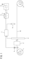
- the equipment configuration of the first processing line includes a payoff reel 1, a tension reel 2, a PLG 3, a plating processing unit 4, a defect inspection device 5, a printing device 6, and a first line control unit 7.
- the present invention is configured such that the payoff reel 1 and the tension reel 2 carry out unwinding/winding processing of a metal strip 10 in the form of the coil, and the metal strip 10 is conveyed from the payoff reel 1 to the tension reel 2.
- the plating processing unit 4 is arranged on the upstream side of the defect inspection device 5 and carries out processing of applying plating to the surface of the metal strip 10.
- the PLG 3 containing an encoder and other components detects the number of rotations of rollers rotating with the conveyance of the metal strip 10, and supplies a detection signal to the first line control unit 7.
- the defect inspection device 5 is a device for detecting defects of the surface and the inside of the metal strip 10 to be conveyed, and, upon detecting a defect, supplies a defect detection signal to the first line control unit 7.
- the printing device 6 is arranged on the downstream side of the defect inspection device 5.
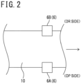
- the printing device 6 includes a printing device for defect marks 6A and a printing device for reference marks 6B as illustrated in FIG. 2 .
- the printing device for defect marks 6A of this embodiment is arranged on the side of an operator (hereinafter also referred to as "OP side") of the metal strip 10, for example.
- the printing device for defect marks 6A prints a defect mark K by ejecting ink to an end part on the OP side of the metal strip 10 based on a printing signal from the first line control unit 7.
- the printing device for reference marks 6B in this embodiment is arranged on a drive side (hereinafter also referred to as "DR side") of the metal strip 10, for example.
- the printing device for reference marks 6B sequentially prints a reference mark S by ejecting ink to the end part on the DR side of the metal strip 10 based on the printing signal from the first line control unit 7. More specifically, in this embodiment, the defect mark K is printed on one end part in the width direction of the metal strip 10 and the reference mark S is printed on the other end part.
- the OP side is the side of an operator in the width direction of the metal strip 10.
- the DR side refers to the side opposite to the OP side, and refers to the equipment side in the width direction of metal strip 10.
- the first line control unit 7 contains a program logic controller (PLC) or the like.
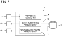
- the first line control unit 7 includes a first position tracking unit 7A, a defect mark printing processing unit 7B, and a reference mark printing processing unit 7C as illustrated in FIG. 3 .
- the first position tracking unit 7A carries out the detection of the line speed of the metal strip 10 and known tracking processing for the longitudinal position from a tip part of the metal strip 10 based on the detection signal from the PLG 3, and arithmetically operates position tracking information.
- the defect mark printing processing unit 7B acquires the longitudinal position of the defect detection position based on the position tracking information from the first position tracking unit 7A.
- the defect mark printing processing unit 7B supplies a printing signal to the printing device for defect marks when the defect detection position in the longitudinal direction comes to the print position by the printing device for defect marks 6A based on the line speed.
- the defect mark printing processing unit 7B supplies the printing signal considering an operation delay.
- the defect mark K is printed on the end part on the OP side of the metal strip 10.
- the defect mark printing processing unit 7B outputs a printing performance data 11 of the printing of the defect mark K via the printing device for defect marks 6A to a database 8.
- Each printing performance data 11 includes a data of a mark type and the print position which is longitudinal position information of the metal strip 10, for example.
- the reference mark printing processing unit 7C performs processing based on the tracking information from the first position tracking unit 7A and the line speed of the metal strip 10. More specifically, the reference mark printing processing unit 7C sequentially outputs a printing signal to the printing device for reference marks 6B such that the reference marks S are printed at equal intervals along the longitudinal direction from a predetermined reference position.
- the predetermined reference position is the reference position in the longitudinal direction away from the unwinding tip of the metal strip 10 by a preset distance.
- the reference marks S are sequentially applied at equal intervals (e.g., every 10 m) along the longitudinal direction to the end part on the DR side of the metal strip 10.
- the plurality of reference marks S may not be printed at equal intervals but may be printed to be arranged with a predetermined regularity along the longitudinal direction.
- the reference mark printing processing unit 7C outputs the printing performance data 11 of the printing of the reference mark S via the printing device for reference marks 6B to the database 8.
- Each printing performance data 11 includes a data of a mark type and the print position which is the longitudinal position information, for example.
- identification information for identifying each reference mark S to each of the plurality of reference marks S.
- the identification information numbers in ascending order of the printing can be exemplified.
- the processing line of printing the plurality of reference marks S may be a line on the upstream side of the first processing line.
- the processing line of printing the plurality of reference marks S and the processing line of printing the defect marks K are the same line (first processing line). More specifically, it is preferable that the printing device for defect marks 6A and the printing device for reference marks 6B face each other in the width direction of the metal strip 10 across the conveyance direction of the metal strip 10 as illustrated in FIG. 2 .
- the configuration is as follows, for example. More specifically, the processing of printing the defect mark by the printing device for defect marks 6A and the processing of printing the reference marks by the printing device for reference marks 6B need not be performed at the same time.
- the tracking information in each line deviates by, for example, about 3% due to the influence of slippage or the like. This causes a deviation of about 30 m at 1000 m, for example.
- the plurality of reference marks S is arranged at equal intervals, for example, along the longitudinal direction of the metal strip 10. Therefore, the first or last reference mark S can be printed close to an end part in a longitudinal direction of the metal strip 10 for example, and therefore information accuracy of the tracking position is high.
- a case is assumed in which the defect mark K is applied in a processing line subsequent to the processing line of applying the reference marks S. In this case, when the print position of the defect mark K is specified while the tracking position is calibrated by the position of the reference mark S, the relative relationship between the longitudinal positions of the reference mark S and each defect mark K is in a highly accurate state.
- An upper computer 9 is an upper computer with respect to the first line control unit 7 and a second line control unit 26 described later.
- the upper computer 9 includes an associated information acquisition unit 9A.
- the associated information acquisition unit 9A is executed after the completion of the processing in the first processing line.
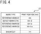
- the associated information acquisition unit 9A carries out processing of arranging the printing performance data 11 in the database 8 in ascending order with the longitudinal position as a key to create a printing performance data group 12 as illustrated in FIG. 4.
- FIG. 4 illustrates a case of cutting the final end of the coil with a cutting device (not illustrated).
- a processing performance data of the cutting position is also obtained as a part of the printing performance data 11.
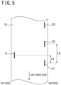
- the printing performance data group 12 illustrated in FIG. 4 is an example of a case where the defect mark K and the reference marks S illustrated in FIG. 5 are applied to the metal strip 10.
- a symbol to that effect may be imparted to the reference mark S for specifying the position of the defect mark K in the printing performance data group 12.
- an identification number may be printed as the reference mark S together with the mark itself.
- numbers to be printed numbers changed in ascending order or in descending order in each printing using a counter, for example, are used.
- a data group of information of the reference mark S for specifying the position of the defect mark K and information of the separation distance from the reference mark S to the target defect mark K may be separately provided.
- the reference mark S for specifying the position of the defect mark K may not be the reference mark S closest to the defect mark K.
- processing of arranging the printing performance data 11 in the database 8 in descending order with the longitudinal position as a key is carried out.
- processing of converting the print position to the longitudinal position from the tip side of the coil is carried out and the printing performance data group 12 is created as illustrated in FIG. 6 .
- the shear cut position that has become the trail end in the first processing line becomes the leading end in the second processing line.
- the processing of the associated information acquisition unit 9A may be carried out by the first line control unit 7 and the second line control unit 26 described later.
- the equipment configuration of the second processing line includes a payoff reel 20, a tension reel 21, a PLG 22, a printed mark recognition device 23, a trimming device 24, a reprinting device 25, and the second line control unit 26.
- the payoff reel 20 and the tension reel 21 carry out the unwinding/rewinding processing of the metal strip 10 in the form of the coil.
- the present invention is configured such that the metal strip 10 is conveyed from the payoff reel 20 toward the tension reel 21.
- the PLG 22 including an encoder and the like detects the number of rotations of rollers rotating with the conveyance of the metal strip 10, and supplies a detection signal to the second line control unit 26.
- the printed mark recognition device 23 constitutes a mark detection unit.
- the printed mark recognition device 23 contains an imaging device, such as a camera, detects the reference mark S applied to the surface of the metal strip 10, and outputs a detection signal to the second line control unit 26. At this time, it may be acceptable that a recognition counter is provided, and, once the reference mark S is detected, the counter is decreased or increased to improve the identification degree of the detected reference mark S.
- the trimming device 24 of this embodiment is arranged on both sides in the width direction of the metal strip 10 and continuously cuts both end edge parts of the metal strip 10 to be conveyed.
- the trimming device 24 in this embodiment performs the cutting before reprinting in the reprinting device 25.
- the trimming device is arranged on the downstream side of the reprinting device 25 and an end part on the reference mark S side (DR side) is cut after reprinting.
- the trimming device is a trimming device cutting the end part on the reference mark S side (DR side) present on the other end part side.
- the defect marks are reprinted on both end parts in the width direction, and therefore the end parts on both sides are cut at the same time.
- the cutting processing by the trimming device 24 is performed.
- the reprinting is performed inside the defect mark printed in the first processing line.
- a metal strip to be subjected to such processing does not require the application of reference marks and also does not require reprinting in many cases.
- the reprinting device 25 of this embodiment ejects ink to the end part of the metal strip 10 based on the printing signal from the second line control unit 26 to reprint the defect mark K serving as the second position specification mark.
- the second line control unit 26 contains a program logic controller (PLC) or the like.
- the second line control unit 26 includes a second position tracking unit 26A and a reprinting processing unit 26B as illustrated in FIG. 8 .
- the second position tracking unit 26A carries out the detection of the line speed of the metal strip 10 and known tracking processing for the longitudinal position from the tip part of the metal strip 10 based on the detection signal from the PLG 22, and arithmetically operates the position tracking information.
- the second position tracking unit 26A of this embodiment refers to the created printing performance data group 12 whenever a detection signal of the printing from the printed mark recognition device 23 is input. Then, the second position tracking unit 26A calibrates the longitudinal position information (tracking information) obtained by the detection by the PLG 22 of the corresponding reference mark S by the longitudinal position of the printing performance data 11, thereby improving the accuracy of the tracking position information.
- the reprinting processing unit 26B refers to the created printing performance data group 12 based on the position tracking information from the second position tracking unit 26A. Then, the reprinting processing unit 26B determines whether the longitudinal position of the printing performance data 11 to the next defect mark K comes to the print position by the reprinting device 25 in the longitudinal direction. When determined as described above, the reprinting processing unit 26B supplies a printing signal to the reprinting device 25. The printing signal is supplied considering an operation delay. Thus, the defect mark K is reprinted on the end part trimmed on the OP side in the metal strip 10.
- the reprinting processing unit 26B refers to the created printing performance data group 12.
- the reprinting processing unit 26B determines whether the detected reference mark S is the previous reference mark S on the upstream side of the printing performance data 11 to the next defect mark K.
- the reprinting processing unit 26B performs the following processing. More specifically, the reprinting processing unit 26B specifies the longitudinal position of the defect mark K from the position information of the reference mark S detected by the printed mark recognition device 23 and the printing performance data group 12.
- the reprinting processing unit 26B supplies a printing signal to the reprinting device 25 based on the line speed. This processing is carried out when it is determined that the position obtained by adding the separation distance from the reference mark S to the defect mark K to the longitudinal position of the determined mark position in the longitudinal direction comes to the print position by the reprinting device 25.
- the printing signal is supplied considering an operation delay.
- the defect mark K is reprinted on the end part trimmed on the OP side in the metal strip 10.
- the reference marks S are printed at equal intervals on the end part on the DR side of the metal strip 10 as illustrated in FIG. 5 in the first processing line.
- the defect mark K is printed on the OP side of the metal strip 10.
- the printing performance data 11 of the defect mark K and the plurality of reference marks S are sequentially stored in the database 8.
- the plurality of printing performance data 11 stored in the database 8 is sorted in ascending order or in descending order with the longitudinal position as a key to form the printing performance data group 12 (see FIGS. 4 , 6 ).
- the reference mark S is detected, and the position tracking information is calibrated by print position information in the printing performance data 11 of the detected reference mark S in the second processing line.
- a printing deviation is calibrated.
- the accuracy of the position tracking information to the defect mark K position in the second processing line is improved.
- the end part on the OP side of the metal strip 10 is trimmed, and then the defect mark K is reprinted at the same longitudinal position as the longitudinal position of the printed defect mark K.
- the longitudinal position for reprinting is specified with the position of the reference mark S as a reference.
- the reprint position of the defect mark K can be specified from a separation distance LA in the longitudinal direction from the reference mark S on the upstream side of the target defect mark K as illustrated in FIG. 5 based on the printing performance data group 12.
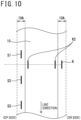
- the defect mark K as the second position specification mark is reprinted as illustrated in FIG. 10 .
- the reprinting of the defect mark K is carried out in both right and left end parts, but the reprinting may be carried out in only one side.
- the reference numerals 10A indicate cut portions of the end parts in the metal strip 10.
- the reprinting is performed by specifying the reprint position in the longitudinal direction based on the printing performance of the defect mark K while the tracking information is calibrated by the reference mark S in the second processing line.
- the use of the plurality of reference marks S arranged according to a predetermined rule enables the reprinting of the defect mark K based on the distance from the reference mark S. Therefore, the possibility of the occurrence of non-detection due to the dense defect marks K can be reduced. Further, the recognition of the dirt 30 as the defect mark K can be prevented.
- the reference marks S are printed at predetermined intervals, such as fixed length intervals. Therefore, an interval deviation between the reference marks S is small, and parts other than the periphery of parts of the printed marks can be masked. This makes it possible to prevent the overlooking caused by recognizing a dirt or the like as a mark. Further, since the non-detection of the reference mark S can be determined depending on the presence or absence of the detection in a part where the reference mark S is to be detected, the non-detection can be early found.
- the plurality of reference marks S is printed and the reprinting is performed with the plurality of reference marks S as a reference, and thus the defect mark K can be reprinted with higher accuracy.
- the processing of the metal strip 10 is processing of manufacturing the metal strip 10, for example.
- the processing is processing of the metal strip 10 for manufacturing a cold-rolled steel sheet.
- the position deviation of the position tracking for applying the second position specification mark is calibrated by the reference marks S arranged in the longitudinal direction according to a certain rule in the second processing line.
- this embodiment makes it possible to perform printing at the same longitudinal position in different processing lines. More specifically, according to this configuration, the tracking deviation can be suppressed to a low degree. This makes it possible to automatically perform printing processing which has been manually performed until now in performing reprinting at the same position.
- This embodiment is a method for processing a metal strip for sequentially applying processing to the same metal strip in a plurality of processing lines including: applying a first position specification mark to the metal strip in a first processing line selected from the plurality of processing lines; applying a plurality of reference marks arranged with a predetermined regularity along the longitudinal direction to the metal strip in the first processing line or in a processing line upstream of the first processing line; cutting a portion of the metal strip, to which the first position specification mark has been applied, in a second processing line as a processing line downstream of the first processing line; and, after the cutting, applying a second position specification mark to the metal strip at the same longitudinal position as the longitudinal position of the first position specification mark in the second processing line, in which the longitudinal position of the first position specification mark is associated with a reference mark selected from the plurality of reference marks, and, in the second processing line, the longitudinal position of the first position specification mark is specified based on position information of the selected reference mark, and the application position of the second position specification mark is determined.
- the position tracking deviation is compensated by the reference marks S arranged in the longitudinal direction according to a certain rule.
- the printing at the same longitudinal position in different processing lines is enabled.
- the tracking deviation can be suppressed to a low degree. This makes it possible to automatically perform printing processing which has been manually performed until now in performing reprinting at the same position.
- the second position specification mark is applied to a portion of an end part in the width direction of the metal strip 10 which has not been removed in the cutting processing in the second processing line.
- the second position specification mark can be applied to the end part of the metal strip 10 with high position accuracy.
- a method for performing reprinting before the trimming has no advantages. This is because the printing in the first processing line and the reprinting have the same information, and therefore there is no need for reprinting.
- identification information for identifying each reference mark S is applied to the plurality of reference marks S.
- each reference mark S can be individually identified.
- the longitudinal position of the first position specification mark is specified from the separation distance in the longitudinal direction of the metal strip 10 from the selected reference mark S.
- the longitudinal position of the first position specification mark can be associated with the selected reference mark S.
- processing of cutting the portion of the metal strip 10, to which the plurality of reference marks S has been applied is performed in the second processing line.
- the processing of cutting the portion of the metal strip 10, to which the plurality of reference marks S has been applied is carried out before applying the second position specification mark.
- the reference mark S can be removed.
- the first position specification mark and the second position specification mark are defect marks K indicating the longitudinal position of a defect present in the metal strip 10.
- the defect mark K can be reprinted with high accuracy.
- This embodiment is a mark application method for applying a mark to a metal strip in sequentially applying processing to the same metal strip in a plurality of processing lines including: applying a first position specification mark specifying the position to the metal strip in a first processing line selected from the plurality of processing lines; applying a plurality of reference marks arranged with a predetermined regularity along the longitudinal direction to the metal strip in the first processing line or in a processing line upstream of the first processing line; applying a second position specification mark at the same longitudinal position as the longitudinal position of the first position specification mark in a second processing line as a processing line downstream of the first processing line; and, in applying the second position specification mark, determining a position at which the second position specification mark is applied by specifying the longitudinal position of the first position specification mark based on the position of a reference mark selected from the plurality of reference marks.
- the position tracking deviation is compensated by the reference marks S arranged in the longitudinal direction according to a certain rule.
- the printing at the same longitudinal position in different processing lines is enabled.
- the tracking deviation can be suppressed to a low degree. This makes it possible to automatically perform printing processing which has been manually performed until now in performing reprinting at the same position.
- This embodiment is a mark application device for applying, in a second processing line selected from a plurality of processing lines in sequentially applying processing to the same metal strip in the plurality of processing lines, a second position specification mark at the same longitudinal position of the metal strip as the position of a first position specification mark which has been applied in a first processing line upstream of the second processing line including: a printing device for reference marks arranged in the first processing line or in a processing line upstream of the first processing line and printing a reference mark to the metal strip; a reference mark printing processing unit carrying out processing of printing a plurality of reference marks arranged with a predetermined regularity along the longitudinal direction to the metal strip via the printing device for reference marks; an associated information acquisition unit obtaining associated information in which the reference mark selected from the plurality of reference marks is associated with the first position specification mark; a mark detection unit provided in the second processing line and detecting the reference mark; a reprinting device arranged in the second processing line and applying the second position specification mark to the metal strip; and carrying out processing of a a
- the position tracking deviation is compensated and calibrated by the reference marks S arranged in the longitudinal direction according to a certain rule.
- the printing at the same longitudinal position in different processing lines is enabled.
- the tracking deviation can be suppressed to a low degree. This makes it possible to automatically perform printing processing which has been manually performed until now in performing reprinting at the same position.
- the plurality of reference marks S may be applied with identification information for identifying each reference mark S.
- the associated information includes information of the separation distance in the longitudinal direction of the metal strip 10 between the longitudinal position of the first position specification mark and the longitudinal position of the reference mark S selected from the plurality of reference marks S.
- the longitudinal position of the first position specification mark can be associated with the selected reference mark S.
Landscapes
- Engineering & Computer Science (AREA)
- Mechanical Engineering (AREA)
- Investigating Materials By The Use Of Optical Means Adapted For Particular Applications (AREA)
- Control Of Metal Rolling (AREA)
Abstract
Description
- The present invention relates to a technology for sequentially applying processing to a metal strip in a plurality of processing lines, such as a processing line of manufacturing a cold-rolled steel sheet. The present invention particularly relates to a technology having a feature in a position tracking method between a plurality of processing lines.
- As conventional position tracking processing, there is a technology described in
Patent Literature 1, for example. -
Patent Literature 1 uses, in a thin steel sheet continuous processing line, a point tracking system using welding points and a method for calculating the conveyance position and the coil length based on detection values of the number of rotations of a roll using a PLG (pulse generator). - Patent Literature 1:
JPH07-32017 A - The tracking by the PLG has a risk of the occurrence of a deviation (error) due to slippage or the like between the steel sheet to be conveyed and a detection roll. Therefore, there is a risk that a deviation occurs between a measured value by one processing line and a measured value by another processing line, i.e., a deviation occurs in the tracking position.
-
Patent Literature 1 corrects the deviation caused by the slippage of the metal strip at the welding point. However, when a coil length deviation occurs, the deviation remains until the welding point with the next coil. Therefore, inPatent Literature 1, even when the amount of each deviation is small, the deviation of the tracking position becomes large when the slip occurs several times. This poses a problem of the occurrence of a longitudinal direction error exceeding the allowable length at the tracking position in the next processing line. - In a processing line of applying electroplating to a steel sheet to which a defect mark has been applied, there is a tendency that the plating adhesion amount to an edge part of the steel sheet increases due to a current concentration. Therefore, the trimming of the edge part is required to improve the quality. However, there is a possibility that a customer uses portions other than a defect part even for a portion of the metal strip with the defect mark. Therefore, it is preferable to print the defect mark as close to the edge part as possible. Therefore, in cutting the edge part where the plating adhesion amount is excessive large, the defect mark (position specification mark) already printed in the edge part is also cut at the same time. Therefore, in a processing line of cutting the edge part, reprinting of the defect mark needs to be performed to the metal strip.
- However, conventionally, there is a risk of the occurrence of a deviation of an amount equal to or larger than a predetermined amount in the tracking position between the processing lines. Therefore, when printing is carried out in another processing line based on the printing performance at the coil longitudinal position based on the tracking position in one processing line, the print position greatly deviates due to a deviation amount resulting from the slippage or the like described above.
- Therefore, the reprinting of a mark requiring high accuracy, such as defective printing, has been conventionally required to be manually performed.
- It is considered that, when the defect mark is printed to the inside in the width direction to be trimmed, the reprinting is not required. However, in general, the required accuracy for edge printing is 2 mm, for example, which is stricter than the meandering amount in the processing line. For the meandering of the metal strip, the printing to the edge can be always put on standby at the edge of the metal strip with the accuracy within 2 mm by moving a mark printing apparatus body using an edge following device. However, a trimmer body cannot be moved. Therefore, it is considered that, after cutting the edge with the trimmer, the reprinting to the edge can be performed. However, a method for leaving defective printing before the trimming is not realistic. Therefore, under present circumstances, the reprinting is carried out after the cutting of the edge.
- The present invention has been made focusing on the above-described points. It is an object of the present invention to carry out the reprinting of a mark with high accuracy in a processing line different from a processing line in which the printing has been performed.
- To solve the problems, one aspect of the present invention is a method for processing a metal strip for sequentially applying processing to the same metal strip in a plurality of processing lines including: applying a first position specification mark to the metal strip in a first processing line selected from the plurality of processing lines; applying a plurality of reference marks arranged with a predetermined regularity along the longitudinal direction to the metal strip in the first processing line or in a processing line upstream of the first processing line; cutting a portion of the metal strip, to which the first position specification mark has been applied, in a second processing line as a processing line downstream of the first processing line;, after the cutting, applying a second position specification mark to the metal strip at the same longitudinal position as the longitudinal position of the first position specification mark; and, before applying the second position specification mark, detecting at least one of the plurality of reference marks and calibrating tracking information for applying the second position specification mark based on position information of the detected reference mark in the second processing line.
- An aspect of the present invention is a method for processing a metal strip for sequentially applying processing to the same metal strip in a plurality of processing lines including: applying a first position specification mark to the metal strip in a first processing line selected from the plurality of processing lines; applying a plurality of reference marks arranged with a predetermined regularity along the longitudinal direction to the metal strip in the first processing line or in a processing line upstream of the first processing line; cutting a portion of the metal strip, to which the first position specification mark has been applied, in a second processing line as a processing line downstream of the first processing line; and, after the cutting, applying a second position specification mark to the metal strip at the same longitudinal position as the longitudinal position of the first position specification mark, in which the longitudinal position of the first position specification mark is associated with a reference mark selected from the plurality of reference marks, and, in the second processing line, the longitudinal position of the first position specification mark is specified based on position information of the selected reference mark, and the application position of the second position specification mark is determined.
- An aspect of the present invention is a mark application method for applying a mark to a metal strip in sequentially applying processing to the same metal strip in a plurality of processing lines including: applying a first position specification mark specifying the position to the metal strip in a first processing line selected from the plurality of processing lines; applying a plurality of reference marks arranged with a predetermined regularity along the longitudinal direction to the metal strip in the first processing line or in a processing line upstream of the first processing line; applying a second position specification mark at the same longitudinal position as the longitudinal position of the first position specification mark in a second processing line as a processing line downstream of the first processing line; and, in applying the second position specification mark, determining a position at which the second position specification mark is applied by specifying the longitudinal position of the first position specification mark based on the position of a reference mark selected from the plurality of reference marks.
- An aspect of the present invention is a mark application device for applying, in a second processing line selected from a plurality of processing lines in sequentially applying processing to the same metal strip in the plurality of processing lines, a second position specification mark at the same longitudinal position of the metal strip as the longitudinal position of a first position specification mark which has been applied in a first processing line upstream of the second processing line including: a printing device for reference marks arranged in the first processing line or in a processing line upstream of the first processing line and printing a reference mark to the metal strip; a reference mark printing processing unit carrying out processing of printing a plurality of reference marks arranged with a predetermined regularity along the longitudinal direction to the metal strip via the printing device for reference marks; an associated information acquisition unit obtaining associated information in which the reference mark selected from the plurality of reference marks is associated with the first position specification mark; a mark detection unit provided in the second processing line and detecting the reference mark; a reprinting device arranged in the second processing line and applying the second position specification mark to the metal strip; and a reprinting processing unit carrying out processing of specifying the longitudinal position of the metal strip of the first position specification mark from the associated information obtained by the associated information acquisition unit and position information of the reference mark detected by the mark detection unit, and printing the second position specification mark via the reprinting device based on the specified longitudinal position.
- According to the aspects of the present invention, a position tracking deviation is compensated (calibrated) by the reference marks arranged in the longitudinal direction according to a certain rule. As a result, the aspects of the present invention enable printing with high accuracy at the same longitudinal position in different processing lines. More specifically, the aspects of the present invention can suppress a tracking deviation to a low degree. Therefore, the aspects of the present invention make it possible to automatically perform printing processing which has been manually performed until now in performing reprinting at the same position.
-
-
FIG. 1 is a view for illustrating an equipment configuration of a first processing line according to an embodiment based on the present invention. -
FIG. 2 is a plan view for illustrating an arrangement of printing devices. -
FIG. 3 is a view for illustrating a configuration of a first processing control unit. -
FIG. 4 is a view illustrating a printingperformance data group 11. -
FIG. 5 is a view illustrating a printing example corresponding toFIG. 4 . -
FIG. 6 is a view illustrating a printingperformance data group 11. -
FIG. 7 is a view for illustrating an equipment configuration of a second processing line according to the embodiment based on the present invention. -
FIG. 8 is a view for illustrating a configuration of a second processing control unit. -
FIG. 9 is a view illustrating a printing example corresponding toFIG. 4 . -
FIG. 10 is a view illustrating an example of reprinting. -
FIG. 11 is a view for illustrating a comparative example. - Next, an embodiment of the present invention will be described with reference to the drawings.
- This embodiment relates to a method for processing a metal strip and processing equipment sequentially applying processing to the same metal strip (steel sheet or the like) in a plurality of processing lines. This embodiment gives a description assuming a processing line of manufacturing a metal strip, particularly a processing line of manufacturing a cold-rolled steel sheet.
- It is noted that the present invention is not limited to the processing line of manufacturing a metal strip. The present invention is applicable to any processing equipment of sequentially applying processing to the same metal strip in a plurality of processing lines.
- This embodiment gives a description taking a case where a metal strip is processed while unwinding the metal strip in the form of a coil, and then the metal strip is wound up again in each processing line as an example. Therefore, the metal strip is sometimes expressed as a coil. The present invention is applicable even when the metal strip is not wound up in each processing line.
- The term "longitudinal direction" as used herein refers to a longitudinal direction (conveyance direction) of the metal strip to be processed.
- This embodiment includes at least a first processing line and a second processing line as the plurality of processing lines.
- The first processing line is a processing line of applying a first position specification mark to the metal strip. The second processing line is a processing line downstream of the first processing line. The second processing line is a processing line of applying a second position specification mark at the same longitudinal position as the longitudinal position of the first position specification mark. In this embodiment, the first position specification mark is a defect mark indicating the longitudinal position of a defect present in the metal strip. The second position specification mark is a reprinted mark of the defect mark. The first position specification mark and the second position specification mark may not have the same shape.
- One or more other processing lines may be provided between the first processing line and the second processing line. In this embodiment, the first processing line is an electroplating processing line.
- The first processing line may not be the electroplating processing line.
- As illustrated in
FIG. 1 , the equipment configuration of the first processing line includes apayoff reel 1, atension reel 2, aPLG 3, aplating processing unit 4, adefect inspection device 5, aprinting device 6, and a firstline control unit 7. - The present invention is configured such that the
payoff reel 1 and thetension reel 2 carry out unwinding/winding processing of ametal strip 10 in the form of the coil, and themetal strip 10 is conveyed from thepayoff reel 1 to thetension reel 2. - The
plating processing unit 4 is arranged on the upstream side of thedefect inspection device 5 and carries out processing of applying plating to the surface of themetal strip 10. - The
PLG 3 containing an encoder and other components detects the number of rotations of rollers rotating with the conveyance of themetal strip 10, and supplies a detection signal to the firstline control unit 7. - The
defect inspection device 5 is a device for detecting defects of the surface and the inside of themetal strip 10 to be conveyed, and, upon detecting a defect, supplies a defect detection signal to the firstline control unit 7. - The
printing device 6 is arranged on the downstream side of thedefect inspection device 5. Theprinting device 6 includes a printing device for defect marks 6A and a printing device forreference marks 6B as illustrated inFIG. 2 . - The printing device for
defect marks 6A of this embodiment is arranged on the side of an operator (hereinafter also referred to as "OP side") of themetal strip 10, for example. The printing device for defect marks 6A prints a defect mark K by ejecting ink to an end part on the OP side of themetal strip 10 based on a printing signal from the firstline control unit 7. - The printing device for
reference marks 6B in this embodiment is arranged on a drive side (hereinafter also referred to as "DR side") of themetal strip 10, for example. The printing device forreference marks 6B sequentially prints a reference mark S by ejecting ink to the end part on the DR side of themetal strip 10 based on the printing signal from the firstline control unit 7. More specifically, in this embodiment, the defect mark K is printed on one end part in the width direction of themetal strip 10 and the reference mark S is printed on the other end part. - The OP side is the side of an operator in the width direction of the
metal strip 10. The DR side refers to the side opposite to the OP side, and refers to the equipment side in the width direction ofmetal strip 10. - The first
line control unit 7 contains a program logic controller (PLC) or the like. The firstline control unit 7 includes a firstposition tracking unit 7A, a defect markprinting processing unit 7B, and a reference markprinting processing unit 7C as illustrated inFIG. 3 . - The first
position tracking unit 7A carries out the detection of the line speed of themetal strip 10 and known tracking processing for the longitudinal position from a tip part of themetal strip 10 based on the detection signal from thePLG 3, and arithmetically operates position tracking information. - Once the defect detection signal from the
defect inspection device 5 is input, the defect markprinting processing unit 7B acquires the longitudinal position of the defect detection position based on the position tracking information from the firstposition tracking unit 7A. The defect markprinting processing unit 7B supplies a printing signal to the printing device for defect marks when the defect detection position in the longitudinal direction comes to the print position by the printing device fordefect marks 6A based on the line speed. The defect markprinting processing unit 7B supplies the printing signal considering an operation delay. Thus, the defect mark K is printed on the end part on the OP side of themetal strip 10. - The defect mark
printing processing unit 7B outputs aprinting performance data 11 of the printing of the defect mark K via the printing device for defect marks 6A to adatabase 8. Eachprinting performance data 11 includes a data of a mark type and the print position which is longitudinal position information of themetal strip 10, for example. - The reference mark
printing processing unit 7C performs processing based on the tracking information from the firstposition tracking unit 7A and the line speed of themetal strip 10. More specifically, the reference markprinting processing unit 7C sequentially outputs a printing signal to the printing device forreference marks 6B such that the reference marks S are printed at equal intervals along the longitudinal direction from a predetermined reference position. The predetermined reference position is the reference position in the longitudinal direction away from the unwinding tip of themetal strip 10 by a preset distance. Thus, the reference marks S are sequentially applied at equal intervals (e.g., every 10 m) along the longitudinal direction to the end part on the DR side of themetal strip 10. The plurality of reference marks S may not be printed at equal intervals but may be printed to be arranged with a predetermined regularity along the longitudinal direction. - The reference mark
printing processing unit 7C outputs theprinting performance data 11 of the printing of the reference mark S via the printing device forreference marks 6B to thedatabase 8. Eachprinting performance data 11 includes a data of a mark type and the print position which is the longitudinal position information, for example. - It is preferable to apply identification information for identifying each reference mark S to each of the plurality of reference marks S. As the identification information, numbers in ascending order of the printing can be exemplified.
- The processing line of printing the plurality of reference marks S may be a line on the upstream side of the first processing line.
- When the processing line of printing the plurality of reference marks S and the processing line of printing the defect marks K are the same line (first processing line), the following configuration is preferable. More specifically, it is preferable that the printing device for defect marks 6A and the printing device for
reference marks 6B face each other in the width direction of themetal strip 10 across the conveyance direction of themetal strip 10 as illustrated inFIG. 2 . When the processing line of printing the plurality of reference marks S and the processing line of printing the defect mark K are the same line, the configuration is as follows, for example. More specifically, the processing of printing the defect mark by the printing device for defect marks 6A and the processing of printing the reference marks by the printing device forreference marks 6B need not be performed at the same time. It does not matter which one is carried out first insofar as the processing is carried out in the same line (first processing line). This is because, when the processing is carried out in the same processing line, the position information of the defect mark and the position information of the reference marks do not have a relative deviation or only a slight deviation in the longitudinal position. - Between the lines, the tracking information in each line deviates by, for example, about 3% due to the influence of slippage or the like. This causes a deviation of about 30 m at 1000 m, for example.
- The plurality of reference marks S is arranged at equal intervals, for example, along the longitudinal direction of the
metal strip 10. Therefore, the first or last reference mark S can be printed close to an end part in a longitudinal direction of themetal strip 10 for example, and therefore information accuracy of the tracking position is high. Herein, a case is assumed in which the defect mark K is applied in a processing line subsequent to the processing line of applying the reference marks S. In this case, when the print position of the defect mark K is specified while the tracking position is calibrated by the position of the reference mark S, the relative relationship between the longitudinal positions of the reference mark S and each defect mark K is in a highly accurate state. - An
upper computer 9 is an upper computer with respect to the firstline control unit 7 and a secondline control unit 26 described later. Theupper computer 9 includes an associatedinformation acquisition unit 9A. - The associated
information acquisition unit 9A is executed after the completion of the processing in the first processing line. The associatedinformation acquisition unit 9A carries out processing of arranging theprinting performance data 11 in thedatabase 8 in ascending order with the longitudinal position as a key to create a printingperformance data group 12 as illustrated inFIG. 4. FIG. 4 illustrates a case of cutting the final end of the coil with a cutting device (not illustrated). A processing performance data of the cutting position is also obtained as a part of theprinting performance data 11. Herein, the printingperformance data group 12 illustrated inFIG. 4 is an example of a case where the defect mark K and the reference marks S illustrated inFIG. 5 are applied to themetal strip 10. - This makes it possible to associate each defect mark K with one or two or more reference marks S selected from the plurality of reference marks S.
- At this time, in a case where identification information is applied to the reference mark S, for example, a symbol to that effect may be imparted to the reference mark S for specifying the position of the defect mark K in the printing
performance data group 12. For example, an identification number may be printed as the reference mark S together with the mark itself. As numbers to be printed, numbers changed in ascending order or in descending order in each printing using a counter, for example, are used. - Further, a data group of information of the reference mark S for specifying the position of the defect mark K and information of the separation distance from the reference mark S to the target defect mark K may be separately provided.
- The reference mark S for specifying the position of the defect mark K may not be the reference mark S closest to the defect mark K.
- Herein, a case is assumed in which an odd number of other processing lines are present between the first processing line and the second processing line. In this case, the unwinding directions of the coil forming the
metal strip 10 in the first processing line and the second processing line are the same. - On the other hand, a case is assumed in which there are no other processing lines or an even number of other processing lines are present between the first processing line and the second processing line. In this case, the directions of the coil to be processed in the first processing line and the second processing line are opposite directions. Therefore, the winding outside of the coil to be processed in the first processing line is the core of the coil to be processed in the second processing line.
- In this case, processing of arranging the
printing performance data 11 in thedatabase 8 in descending order with the longitudinal position as a key is carried out. Then, processing of converting the print position to the longitudinal position from the tip side of the coil is carried out and the printingperformance data group 12 is created as illustrated inFIG. 6 . In this case, the shear cut position that has become the trail end in the first processing line becomes the leading end in the second processing line. - The processing of the associated
information acquisition unit 9A may be carried out by the firstline control unit 7 and the secondline control unit 26 described later. - As illustrated in
FIG. 7 , the equipment configuration of the second processing line includes apayoff reel 20, atension reel 21, aPLG 22, a printedmark recognition device 23, atrimming device 24, areprinting device 25, and the secondline control unit 26. - The
payoff reel 20 and thetension reel 21 carry out the unwinding/rewinding processing of themetal strip 10 in the form of the coil. The present invention is configured such that themetal strip 10 is conveyed from thepayoff reel 20 toward thetension reel 21. - The
PLG 22 including an encoder and the like detects the number of rotations of rollers rotating with the conveyance of themetal strip 10, and supplies a detection signal to the secondline control unit 26. - The printed
mark recognition device 23 constitutes a mark detection unit. The printedmark recognition device 23 contains an imaging device, such as a camera, detects the reference mark S applied to the surface of themetal strip 10, and outputs a detection signal to the secondline control unit 26. At this time, it may be acceptable that a recognition counter is provided, and, once the reference mark S is detected, the counter is decreased or increased to improve the identification degree of the detected reference mark S. - The trimming
device 24 of this embodiment is arranged on both sides in the width direction of themetal strip 10 and continuously cuts both end edge parts of themetal strip 10 to be conveyed. The trimmingdevice 24 in this embodiment performs the cutting before reprinting in thereprinting device 25. - A case is assumed in which the reprinting of the defect mark is carried out only on one end part side in the width direction. In this case, it may be acceptable that the trimming device is arranged on the downstream side of the
reprinting device 25 and an end part on the reference mark S side (DR side) is cut after reprinting. The trimming device is a trimming device cutting the end part on the reference mark S side (DR side) present on the other end part side. - In this embodiment, the defect marks are reprinted on both end parts in the width direction, and therefore the end parts on both sides are cut at the same time.
- It is also considered that, after the reprinting by the reprinting
device 25, the cutting processing by the trimmingdevice 24 is performed. However, in this case, the reprinting is performed inside the defect mark printed in the first processing line. However, a metal strip to be subjected to such processing does not require the application of reference marks and also does not require reprinting in many cases. Further, there is also a problem that, when the reprinting is performed before the cutting of the end parts, the cutting width becomes larger than necessary. - The reprinting
device 25 of this embodiment ejects ink to the end part of themetal strip 10 based on the printing signal from the secondline control unit 26 to reprint the defect mark K serving as the second position specification mark. - The second
line control unit 26 contains a program logic controller (PLC) or the like. The secondline control unit 26 includes a secondposition tracking unit 26A and areprinting processing unit 26B as illustrated inFIG. 8 . - The second
position tracking unit 26A carries out the detection of the line speed of themetal strip 10 and known tracking processing for the longitudinal position from the tip part of themetal strip 10 based on the detection signal from thePLG 22, and arithmetically operates the position tracking information. - The second
position tracking unit 26A of this embodiment refers to the created printingperformance data group 12 whenever a detection signal of the printing from the printedmark recognition device 23 is input. Then, the secondposition tracking unit 26A calibrates the longitudinal position information (tracking information) obtained by the detection by thePLG 22 of the corresponding reference mark S by the longitudinal position of theprinting performance data 11, thereby improving the accuracy of the tracking position information. - The reprinting
processing unit 26B refers to the created printingperformance data group 12 based on the position tracking information from the secondposition tracking unit 26A. Then, the reprintingprocessing unit 26B determines whether the longitudinal position of theprinting performance data 11 to the next defect mark K comes to the print position by the reprintingdevice 25 in the longitudinal direction. When determined as described above, the reprintingprocessing unit 26B supplies a printing signal to thereprinting device 25. The printing signal is supplied considering an operation delay. Thus, the defect mark K is reprinted on the end part trimmed on the OP side in themetal strip 10. - Alternatively, if a detection signal of the reference mark S from the printed
mark recognition device 23 is input, the reprintingprocessing unit 26B refers to the created printingperformance data group 12. The reprintingprocessing unit 26B determines whether the detected reference mark S is the previous reference mark S on the upstream side of theprinting performance data 11 to the next defect mark K. When the detected reference mark S is the previous reference mark S on the upstream side of theprinting performance data 11 to the next defect mark K, the reprintingprocessing unit 26B performs the following processing. More specifically, the reprintingprocessing unit 26B specifies the longitudinal position of the defect mark K from the position information of the reference mark S detected by the printedmark recognition device 23 and the printingperformance data group 12. Then, the reprintingprocessing unit 26B supplies a printing signal to thereprinting device 25 based on the line speed. This processing is carried out when it is determined that the position obtained by adding the separation distance from the reference mark S to the defect mark K to the longitudinal position of the determined mark position in the longitudinal direction comes to the print position by the reprintingdevice 25. The printing signal is supplied considering an operation delay. Thus, the defect mark K is reprinted on the end part trimmed on the OP side in themetal strip 10. - In this embodiment, the reference marks S are printed at equal intervals on the end part on the DR side of the
metal strip 10 as illustrated inFIG. 5 in the first processing line. In the first processing line, the defect mark K is printed on the OP side of themetal strip 10. In the first processing line, theprinting performance data 11 of the defect mark K and the plurality of reference marks S are sequentially stored in thedatabase 8. - The plurality of
printing performance data 11 stored in thedatabase 8 is sorted in ascending order or in descending order with the longitudinal position as a key to form the printing performance data group 12 (seeFIGS. 4 ,6 ). - Further, in the embodiment, the reference mark S is detected, and the position tracking information is calibrated by print position information in the
printing performance data 11 of the detected reference mark S in the second processing line. Thus, a printing deviation is calibrated. As a result, the accuracy of the position tracking information to the defect mark K position in the second processing line is improved. - In the second processing line, the end part on the OP side of the
metal strip 10 is trimmed, and then the defect mark K is reprinted at the same longitudinal position as the longitudinal position of the printed defect mark K. - At this time, the longitudinal position for reprinting is specified with the position of the reference mark S as a reference.
- Herein, a case is assumed in which the longitudinal directions of the coil in the first processing line and the second processing line are the same. In this case, the reprint position of the defect mark K can be specified from a separation distance LA in the longitudinal direction from the reference mark S on the upstream side of the target defect mark K as illustrated in
FIG. 5 based on the printingperformance data group 12. - On the other hand, a case is assumed in which the longitudinal directions of the coil in the first processing line and the second processing line are reversed. In this case, the reprint position of the defect mark K can be specified from a separation distance LB in the longitudinal direction from the reference mark S on the upstream side of the target defect mark K as illustrated in
FIG. 9 . Since a distance L0 between the reference marks S adjacent to each other is already known, the separation distance LB can be determined based on L0 - LA = LB. - At the position advanced by the separation distance LA or LB from the tracking position of the reference mark S selected from the plurality of reference marks S, the defect mark K as the second position specification mark is reprinted as illustrated in
FIG. 10 . InFIG. 10 , the reprinting of the defect mark K is carried out in both right and left end parts, but the reprinting may be carried out in only one side. InFIG. 10 , thereference numerals 10A indicate cut portions of the end parts in themetal strip 10. - Alternatively, in this embodiment, the reprinting is performed by specifying the reprint position in the longitudinal direction based on the printing performance of the defect mark K while the tracking information is calibrated by the reference mark S in the second processing line.
- It is theoretically possible to detect the defect mark K, which has been printed in the first processing line, in the second processing line and print it at the same longitudinal position of the steel sheet as the longitudinal position of the defect mark K, without printing the plurality of reference marks S. However, there is a possibility that the defect mark K cannot yet be detected or overlooked.
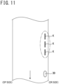
- This is because of the following reasons. When the printed mark is detected at the line speed, a camera cannot recognize the type of the mark, and therefore only the presence or absence of the printing is detected. Therefore, when the defect marks K are densely continuous as illustrated in
FIG. 11 , there is a possibility that the plurality of marks is recognized as one mark and some of the defect marks K are not detected. There is also a possibility of recognizing and over-detecting adirt 30 as the defect mark K. When such two identification errors occur, the defect marks K are shifted by one, for example. This results in a difference between the defect type and the printed mark for all defects after the mark for which the identification error occurs, which leads to a serious quality error. - In contrast thereto, in this embodiment, the use of the plurality of reference marks S arranged according to a predetermined rule enables the reprinting of the defect mark K based on the distance from the reference mark S. Therefore, the possibility of the occurrence of non-detection due to the dense defect marks K can be reduced. Further, the recognition of the
dirt 30 as the defect mark K can be prevented. - Further, in this embodiment, the reference marks S are printed at predetermined intervals, such as fixed length intervals. Therefore, an interval deviation between the reference marks S is small, and parts other than the periphery of parts of the printed marks can be masked. This makes it possible to prevent the overlooking caused by recognizing a dirt or the like as a mark. Further, since the non-detection of the reference mark S can be determined depending on the presence or absence of the detection in a part where the reference mark S is to be detected, the non-detection can be early found.
- As described above, in this embodiment, the plurality of reference marks S is printed and the reprinting is performed with the plurality of reference marks S as a reference, and thus the defect mark K can be reprinted with higher accuracy.
-
- (1) This embodiment is a method for processing a metal strip for sequentially applying processing to the same metal strip in a plurality of processing lines including: applying a first position specification mark to the metal strip in a first processing line selected from the plurality of processing lines; applying a plurality of reference marks arranged with a predetermined regularity along the longitudinal direction to the metal strip in the first processing line or in a processing line upstream of the first processing line; cutting a portion of the metal strip, to which the first position specification mark has been applied, in a second processing line as a processing line downstream of the first processing line;, after the cutting, applying a second position specification mark to the metal strip at the same longitudinal position as the longitudinal position of the first position specification mark in the second processing line; and, before applying the second position specification mark, detecting at least one of the plurality of reference marks and calibrating tracking information for applying the second position specification mark based on position information of the detected reference mark in the second processing line.
- The processing of the
metal strip 10 is processing of manufacturing themetal strip 10, for example. The processing is processing of themetal strip 10 for manufacturing a cold-rolled steel sheet. - According to this configuration, the position deviation of the position tracking for applying the second position specification mark is calibrated by the reference marks S arranged in the longitudinal direction according to a certain rule in the second processing line. As a result, this embodiment makes it possible to perform printing at the same longitudinal position in different processing lines. More specifically, according to this configuration, the tracking deviation can be suppressed to a low degree. This makes it possible to automatically perform printing processing which has been manually performed until now in performing reprinting at the same position.
- (2) This embodiment is a method for processing a metal strip for sequentially applying processing to the same metal strip in a plurality of processing lines including: applying a first position specification mark to the metal strip in a first processing line selected from the plurality of processing lines; applying a plurality of reference marks arranged with a predetermined regularity along the longitudinal direction to the metal strip in the first processing line or in a processing line upstream of the first processing line; cutting a portion of the metal strip, to which the first position specification mark has been applied, in a second processing line as a processing line downstream of the first processing line; and, after the cutting, applying a second position specification mark to the metal strip at the same longitudinal position as the longitudinal position of the first position specification mark in the second processing line, in which the longitudinal position of the first position specification mark is associated with a reference mark selected from the plurality of reference marks, and, in the second processing line, the longitudinal position of the first position specification mark is specified based on position information of the selected reference mark, and the application position of the second position specification mark is determined.
- According to this configuration, the position tracking deviation is compensated by the reference marks S arranged in the longitudinal direction according to a certain rule. As a result, the printing at the same longitudinal position in different processing lines is enabled. More specifically, according to this configuration, the tracking deviation can be suppressed to a low degree. This makes it possible to automatically perform printing processing which has been manually performed until now in performing reprinting at the same position.
- (3) In this embodiment, after the processing of cutting (trimming) a portion of the
metal strip 10, to which the first position specification mark has been applied, the second position specification mark (reprinting mark) is applied to a portion of an end part in the width direction of themetal strip 10 which has not been removed in the cutting processing in the second processing line. - In this case, the processing of cutting the portion of the
metal strip 10, to which the first position specification mark has been applied, is carried out before applying the second position specification mark. - According to this configuration, the second position specification mark can be applied to the end part of the
metal strip 10 with high position accuracy. - A method for performing reprinting before the trimming has no advantages. This is because the printing in the first processing line and the reprinting have the same information, and therefore there is no need for reprinting.
- (4) In this embodiment, identification information for identifying each reference mark S is applied to the plurality of reference marks S.
- According to this configuration, each reference mark S can be individually identified.
- (5) In this embodiment, the longitudinal position of the first position specification mark is specified from the separation distance in the longitudinal direction of the
metal strip 10 from the selected reference mark S. - According to this configuration, the longitudinal position of the first position specification mark can be associated with the selected reference mark S.
- (6) In this embodiment, processing of cutting the portion of the
metal strip 10, to which the plurality of reference marks S has been applied, is performed in the second processing line. - For example, the processing of cutting the portion of the
metal strip 10, to which the plurality of reference marks S has been applied, is carried out before applying the second position specification mark. - According to this configuration, the reference mark S can be removed.
- (7) In this embodiment, the first position specification mark and the second position specification mark are defect marks K indicating the longitudinal position of a defect present in the
metal strip 10. - According to this configuration, the defect mark K can be reprinted with high accuracy.
- (8) This embodiment is a mark application method for applying a mark to a metal strip in sequentially applying processing to the same metal strip in a plurality of processing lines including: applying a first position specification mark specifying the position to the metal strip in a first processing line selected from the plurality of processing lines; applying a plurality of reference marks arranged with a predetermined regularity along the longitudinal direction to the metal strip in the first processing line or in a processing line upstream of the first processing line; applying a second position specification mark at the same longitudinal position as the longitudinal position of the first position specification mark in a second processing line as a processing line downstream of the first processing line; and, in applying the second position specification mark, determining a position at which the second position specification mark is applied by specifying the longitudinal position of the first position specification mark based on the position of a reference mark selected from the plurality of reference marks.
- According to this configuration, the position tracking deviation is compensated by the reference marks S arranged in the longitudinal direction according to a certain rule. As a result, the printing at the same longitudinal position in different processing lines is enabled. More specifically, according to this configuration, the tracking deviation can be suppressed to a low degree. This makes it possible to automatically perform printing processing which has been manually performed until now in performing reprinting at the same position.
- (9) This embodiment is a mark application device for applying, in a second processing line selected from a plurality of processing lines in sequentially applying processing to the same metal strip in the plurality of processing lines, a second position specification mark at the same longitudinal position of the metal strip as the position of a first position specification mark which has been applied in a first processing line upstream of the second processing line including: a printing device for reference marks arranged in the first processing line or in a processing line upstream of the first processing line and printing a reference mark to the metal strip; a reference mark printing processing unit carrying out processing of printing a plurality of reference marks arranged with a predetermined regularity along the longitudinal direction to the metal strip via the printing device for reference marks; an associated information acquisition unit obtaining associated information in which the reference mark selected from the plurality of reference marks is associated with the first position specification mark; a mark detection unit provided in the second processing line and detecting the reference mark; a reprinting device arranged in the second processing line and applying the second position specification mark to the metal strip; and carrying out processing of a reprinting processing unit specifying the longitudinal position of the metal strip of the first position specification mark from the associated information obtained by the associated information acquisition unit and position information of the reference mark detected by the mark detection unit, and printing the second position specification mark via the reprinting device based on the specified longitudinal position.
- According to this configuration, the position tracking deviation is compensated and calibrated by the reference marks S arranged in the longitudinal direction according to a certain rule. As a result, the printing at the same longitudinal position in different processing lines is enabled. More specifically, according to this configuration, the tracking deviation can be suppressed to a low degree. This makes it possible to automatically perform printing processing which has been manually performed until now in performing reprinting at the same position.
- (10) The plurality of reference marks S may be applied with identification information for identifying each reference mark S.
- According to this configuration, the identification of each reference mark S is facilitated.
- (11) In this embodiment, the associated information includes information of the separation distance in the longitudinal direction of the
metal strip 10 between the longitudinal position of the first position specification mark and the longitudinal position of the reference mark S selected from the plurality of reference marks S. - According to this configuration, the longitudinal position of the first position specification mark can be associated with the selected reference mark S.
- The entire contents of
JP 2020-164011 A (filed September 29, 2020 -
- 1
- payoff reel
- 2
- tension reel
- 2,
- PLG
- 4
- plating processing unit
- 5
- defect inspection device
- 6
- printing device
- 6A
- printing device for defect marks
- 6B
- printing device for reference marks
- 7
- first line control unit
- 7A
- first position tracking unit
- 7B
- defect mark printing processing unit
- 7C
- reference mark printing processing unit
- 8
- database
- 9
- upper computer
- 9A
- associated information acquisition unit
- 10
- metal strip
- 11
- printing performance data
- 12
- printing performance data group
- 20
- payoff reel
- 21
- tension reel
- 21,
- PLG
- 23
- printed mark recognition device
- 24
- trimming device
- 25
- reprinting device
- 26
- second line control unit
- 26A
- second position tracking unit
- 26B
- reprinting processing unit
- K
- defect mark
- S
- reference mark
Claims (14)
- A method for processing a metal strip for sequentially applying processing to a same metal strip in a plurality of processing lines comprising:applying a first position specification mark to the metal strip in a first processing line selected from the plurality of processing lines;applying a plurality of reference marks arranged with a predetermined regularity along a longitudinal direction to the metal strip in the first processing line or in a processing line upstream of the first processing line;cutting a portion of the metal strip, to which the first position specification mark has been applied, in a second processing line as a processing line downstream of the first processing line;after the cutting, applying a second position specification mark to the metal strip at the same longitudinal position as a longitudinal position of the first position specification mark in the second processing line; andbefore applying the second position specification mark, detecting at least one of the plurality of reference marks and calibrating tracking information for applying the second position specification mark based on position information of the detected reference mark in the second processing line.
- A method for processing a metal strip for sequentially applying processing to a same metal strip in a plurality of processing lines comprising:applying a first position specification mark to the metal strip in a first processing line selected from the plurality of processing lines;applying a plurality of reference marks arranged with a predetermined regularity along a longitudinal direction to the metal strip in the first processing line or in a processing line upstream of the first processing line;cutting a portion of the metal strip, to which the first position specification mark has been applied, in a second processing line as a processing line downstream of the first processing line; andafter the cutting, applying a second position specification mark to the metal strip at a same longitudinal position as a longitudinal position of the first position specification mark in the second processing line, whereinthe longitudinal position of the first position specification mark is associated with a reference mark selected from the plurality of reference marks, andin the second processing line, the longitudinal position of the first position specification mark is specified based on position information of the selected reference mark, and an application position of the second position specification mark is determined.
- The method for processing a metal strip according to claim 1 or 2, comprising applying identification information for identifying each reference mark to the plurality of reference marks.
- The method for processing a metal strip according to claim 2 or 3, comprising specifying the longitudinal position of the first position specification mark from a separation distance in a longitudinal direction of the metal strip from the selected reference mark.
- The method for processing a metal strip according to any one of claims 1 to 4, comprising performing processing of cutting a portion of the metal strip, to which the plurality of reference marks has been applied, in the second processing line.
- The method for processing a metal strip according to claim 5, wherein the processing of cutting the portion of the metal strip, to which the plurality of reference marks has been applied, is carried out before applying the second position specification mark.
- The method for processing a metal strip according to any one of claims 1 to 6, wherein the first position specification mark and the second position specification mark are defect marks indicating a longitudinal position of a defect present in the metal strip.
- A method for manufacturing a metal strip comprising:
the method for processing a metal strip according to any one of claims 1 to 7. - The method for manufacturing a metal strip according to claim 8, wherein a cold-rolled steel sheet is manufactured.
- A mark application method for applying a mark to a metal strip in sequentially applying processing to a same metal strip in a plurality of processing lines,
the mark application method comprising:applying a first position specification mark specifying a position to the metal strip in a first processing line selected from the plurality of processing lines;applying a plurality of reference marks arranged with a predetermined regularity along a longitudinal direction to the metal strip in the first processing line or in a processing line upstream of the first processing line;applying a second position specification mark at a same longitudinal position as a longitudinal position of the first position specification mark in a second processing line as a processing line downstream of the first processing line; andin applying the second position specification mark, determining a position at which the second position specification mark is applied by specifying the longitudinal position of the first position specification mark based on a position of a reference mark selected from the plurality of reference marks. - A mark printing device for applying, in a second processing line selected from a plurality of processing lines in sequentially applying processing to a same metal strip in the plurality of processing lines, a second position specification mark at a same longitudinal position of the metal strip as a longitudinal position of a first position specification mark which has been applied in a first processing line upstream of the second processing line,
the mark printing device comprising:a printing device for reference marks arranged in the first processing line or in a processing line upstream of the first processing line and configured to print a reference mark to the metal strip;a reference mark printing processing unit configured to carry out processing of printing a plurality of reference marks arranged with a predetermined regularity along the longitudinal direction to the metal strip via the printing device for reference marks;an associated information acquisition unit configured to obtain associated information in which the reference mark selected from the plurality of reference marks is associated with the first position specification mark;a mark detection unit provided in the second processing line and configured to detect the reference mark;a reprinting device arranged in the second processing line and configured to apply the second position specification mark to the metal strip; anda reprinting processing unit configured to carry out processing of specifying the longitudinal position of the metal strip of the first position specification mark from the associated information obtained by the associated information acquisition unit and position information of the reference mark detected by the mark detection unit, and printing the second position specification mark via the reprinting device based on the specified longitudinal position. - The mark printing device according to claim 11, wherein the plurality of reference marks is applied with identification information for identifying each reference mark.
- The mark printing device according to claim 11 or 12, wherein the associated information includes information of a separation distance in a longitudinal direction of the metal strip between a longitudinal position of the first position specification mark and a longitudinal position of the reference mark selected from the plurality of reference marks.
- The mark printing device according to any one of claims 11 to 13, wherein the first position specification mark and the second position specification mark are defect marks indicating a longitudinal position of a defect present in the metal strip.
Applications Claiming Priority (2)
| Application Number | Priority Date | Filing Date | Title |
|---|---|---|---|
| JP2020164011A JP7028296B1 (en) | 2020-09-29 | 2020-09-29 | Metal strip processing method, mark applying method, and mark printing device |
| PCT/JP2021/024510 WO2022070534A1 (en) | 2020-09-29 | 2021-06-29 | Method for processing metal strip, mark application method, and mark printing device |
Publications (3)
| Publication Number | Publication Date |
|---|---|
| EP4223429A1 true EP4223429A1 (en) | 2023-08-09 |
| EP4223429A4 EP4223429A4 (en) | 2024-08-14 |
| EP4223429B1 EP4223429B1 (en) | 2025-02-19 |
Family
ID=80949851
Family Applications (1)
| Application Number | Title | Priority Date | Filing Date |
|---|---|---|---|
| EP21874838.2A Active EP4223429B1 (en) | 2020-09-29 | 2021-06-29 | Method for processing metal strip with mark application |
Country Status (4)
| Country | Link |
|---|---|
| EP (1) | EP4223429B1 (en) |
| JP (1) | JP7028296B1 (en) |
| MX (1) | MX2023003642A (en) |
| WO (1) | WO2022070534A1 (en) |
Family Cites Families (4)
| Publication number | Priority date | Publication date | Assignee | Title |
|---|---|---|---|---|
| JP2001179336A (en) * | 2000-11-07 | 2001-07-03 | Nkk Corp | Manufacturing method of steel sheet with mark |
| JP3870313B2 (en) * | 2001-03-15 | 2007-01-17 | Jfeスチール株式会社 | How to work with coils marked for defects |
| JP4374968B2 (en) * | 2003-09-30 | 2009-12-02 | Jfeスチール株式会社 | Strip-like material inspection method and apparatus, and marking control method and apparatus |
| JP7182077B2 (en) | 2019-03-29 | 2022-12-02 | いすゞ自動車株式会社 | Vehicle cab rear structure |
-
2020
- 2020-09-29 JP JP2020164011A patent/JP7028296B1/en active Active
-
2021
- 2021-06-29 MX MX2023003642A patent/MX2023003642A/en unknown
- 2021-06-29 EP EP21874838.2A patent/EP4223429B1/en active Active
- 2021-06-29 WO PCT/JP2021/024510 patent/WO2022070534A1/en not_active Ceased
Also Published As
| Publication number | Publication date |
|---|---|
| JP2022056158A (en) | 2022-04-08 |
| EP4223429A4 (en) | 2024-08-14 |
| WO2022070534A1 (en) | 2022-04-07 |
| JP7028296B1 (en) | 2022-03-02 |
| EP4223429B1 (en) | 2025-02-19 |
| MX2023003642A (en) | 2023-04-13 |
Similar Documents
| Publication | Publication Date | Title |
|---|---|---|
| EP2200920B1 (en) | Accurate tracking of web features through converting processes | |
| US20120194791A1 (en) | Device and method for processing printing substrate web into printed products | |
| CN115924608B (en) | Equipment control method, device, controller, electronic equipment and equipment control system | |
| US20210221152A1 (en) | Printing apparatus | |
| CN111572214B (en) | Coiled material tail marking and head identification method | |
| EP4223429B1 (en) | Method for processing metal strip with mark application | |
| EP3885744A1 (en) | Mapping and removing a defect from a web material | |
| US20230347615A1 (en) | A Process for Automatically Correcting Defects on Self-Adhesive Labels on a Continuous Band | |
| US9142023B2 (en) | Maintaining registration of spatially synchronized data for web products | |
| US8740061B2 (en) | Recording information for a web manufacturing process | |
| JP7814494B2 (en) | System and method for calculating additional local stretch in a web | |
| JP7567820B2 (en) | METHOD FOR PROCESSING METAL STRIPES, METHOD FOR PRODUCING METAL STRIPES, AND PRINTING CONDITION DETERMINATION DEVICE | |
| JP2020044789A (en) | Image formation apparatus and manufacturing system of image formation object | |
| JP2014083801A (en) | Prints production management system, rewinding machine, and slitter machine | |
| JP4374968B2 (en) | Strip-like material inspection method and apparatus, and marking control method and apparatus | |
| JP5929443B2 (en) | Defect management system | |
| US11820124B2 (en) | Continuous-forms color measurement system | |
| JP2014191411A (en) | Film production management system, rewinding machine and slitter machine | |
| EP4310040A1 (en) | Method and system for computer-implemented tracking of production history of a continuous web | |
| JP2007125581A (en) | Defect marking and defect removal method and apparatus for steel plate | |
| JP2010054253A (en) | On-line method for controlling quality of steel plate | |
| JPH0724528A (en) | Longitudinal position marking steel strip coil | |
| JP3362621B2 (en) | Defective position inspection method and device | |
| JP2023038809A (en) | Method for removing defective part of sheet body capable of addressing defective part due to plural processes and winding device | |
| JPH08245056A (en) | Defective data correction device and defective processing control device |
Legal Events
| Date | Code | Title | Description |
|---|---|---|---|
| STAA | Information on the status of an ep patent application or granted ep patent |
Free format text: STATUS: THE INTERNATIONAL PUBLICATION HAS BEEN MADE |
|
| PUAI | Public reference made under article 153(3) epc to a published international application that has entered the european phase |
Free format text: ORIGINAL CODE: 0009012 |
|
| STAA | Information on the status of an ep patent application or granted ep patent |
Free format text: STATUS: REQUEST FOR EXAMINATION WAS MADE |
|
| 17P | Request for examination filed |
Effective date: 20230320 |
|
| AK | Designated contracting states |
Kind code of ref document: A1 Designated state(s): AL AT BE BG CH CY CZ DE DK EE ES FI FR GB GR HR HU IE IS IT LI LT LU LV MC MK MT NL NO PL PT RO RS SE SI SK SM TR |
|
| DAV | Request for validation of the european patent (deleted) | ||
| DAX | Request for extension of the european patent (deleted) | ||
| A4 | Supplementary search report drawn up and despatched |
Effective date: 20240621 |
|
| RIC1 | Information provided on ipc code assigned before grant |
Ipc: C23C 2/06 20060101ALI20240618BHEP Ipc: B21B 38/00 20060101ALI20240618BHEP Ipc: B21C 51/00 20060101AFI20240618BHEP |
|
| RA4 | Supplementary search report drawn up and despatched (corrected) |
Effective date: 20240715 |
|
| GRAP | Despatch of communication of intention to grant a patent |
Free format text: ORIGINAL CODE: EPIDOSNIGR1 |
|
| STAA | Information on the status of an ep patent application or granted ep patent |
Free format text: STATUS: GRANT OF PATENT IS INTENDED |
|
| INTG | Intention to grant announced |
Effective date: 20241115 |
|
| GRAS | Grant fee paid |
Free format text: ORIGINAL CODE: EPIDOSNIGR3 |
|
| GRAA | (expected) grant |
Free format text: ORIGINAL CODE: 0009210 |
|
| STAA | Information on the status of an ep patent application or granted ep patent |
Free format text: STATUS: THE PATENT HAS BEEN GRANTED |
|
| AK | Designated contracting states |
Kind code of ref document: B1 Designated state(s): AL AT BE BG CH CY CZ DE DK EE ES FI FR GB GR HR HU IE IS IT LI LT LU LV MC MK MT NL NO PL PT RO RS SE SI SK SM TR |
|
| REG | Reference to a national code |
Ref country code: GB Ref legal event code: FG4D |
|
| REG | Reference to a national code |
Ref country code: CH Ref legal event code: EP |
|
| REG | Reference to a national code |
Ref country code: IE Ref legal event code: FG4D |
|
| REG | Reference to a national code |
Ref country code: DE Ref legal event code: R096 Ref document number: 602021026554 Country of ref document: DE |
|
| REG | Reference to a national code |
Ref country code: NL Ref legal event code: MP Effective date: 20250219 |
|
| PG25 | Lapsed in a contracting state [announced via postgrant information from national office to epo] |
Ref country code: RS Free format text: LAPSE BECAUSE OF FAILURE TO SUBMIT A TRANSLATION OF THE DESCRIPTION OR TO PAY THE FEE WITHIN THE PRESCRIBED TIME-LIMIT Effective date: 20250519 |
|
| PG25 | Lapsed in a contracting state [announced via postgrant information from national office to epo] |
Ref country code: FI Free format text: LAPSE BECAUSE OF FAILURE TO SUBMIT A TRANSLATION OF THE DESCRIPTION OR TO PAY THE FEE WITHIN THE PRESCRIBED TIME-LIMIT Effective date: 20250219 |
|
| PG25 | Lapsed in a contracting state [announced via postgrant information from national office to epo] |
Ref country code: PL Free format text: LAPSE BECAUSE OF FAILURE TO SUBMIT A TRANSLATION OF THE DESCRIPTION OR TO PAY THE FEE WITHIN THE PRESCRIBED TIME-LIMIT Effective date: 20250219 |
|
| PG25 | Lapsed in a contracting state [announced via postgrant information from national office to epo] |
Ref country code: ES Free format text: LAPSE BECAUSE OF FAILURE TO SUBMIT A TRANSLATION OF THE DESCRIPTION OR TO PAY THE FEE WITHIN THE PRESCRIBED TIME-LIMIT Effective date: 20250219 |
|
| REG | Reference to a national code |
Ref country code: LT Ref legal event code: MG9D |
|
| PG25 | Lapsed in a contracting state [announced via postgrant information from national office to epo] |
Ref country code: IS Free format text: LAPSE BECAUSE OF FAILURE TO SUBMIT A TRANSLATION OF THE DESCRIPTION OR TO PAY THE FEE WITHIN THE PRESCRIBED TIME-LIMIT Effective date: 20250619 Ref country code: NO Free format text: LAPSE BECAUSE OF FAILURE TO SUBMIT A TRANSLATION OF THE DESCRIPTION OR TO PAY THE FEE WITHIN THE PRESCRIBED TIME-LIMIT Effective date: 20250519 |
|
| PG25 | Lapsed in a contracting state [announced via postgrant information from national office to epo] |
Ref country code: NL Free format text: LAPSE BECAUSE OF FAILURE TO SUBMIT A TRANSLATION OF THE DESCRIPTION OR TO PAY THE FEE WITHIN THE PRESCRIBED TIME-LIMIT Effective date: 20250219 |
|
| PG25 | Lapsed in a contracting state [announced via postgrant information from national office to epo] |
Ref country code: HR Free format text: LAPSE BECAUSE OF FAILURE TO SUBMIT A TRANSLATION OF THE DESCRIPTION OR TO PAY THE FEE WITHIN THE PRESCRIBED TIME-LIMIT Effective date: 20250219 |
|
| PG25 | Lapsed in a contracting state [announced via postgrant information from national office to epo] |
Ref country code: LV Free format text: LAPSE BECAUSE OF FAILURE TO SUBMIT A TRANSLATION OF THE DESCRIPTION OR TO PAY THE FEE WITHIN THE PRESCRIBED TIME-LIMIT Effective date: 20250219 Ref country code: PT Free format text: LAPSE BECAUSE OF FAILURE TO SUBMIT A TRANSLATION OF THE DESCRIPTION OR TO PAY THE FEE WITHIN THE PRESCRIBED TIME-LIMIT Effective date: 20250620 |
|
| PG25 | Lapsed in a contracting state [announced via postgrant information from national office to epo] |
Ref country code: BG Free format text: LAPSE BECAUSE OF FAILURE TO SUBMIT A TRANSLATION OF THE DESCRIPTION OR TO PAY THE FEE WITHIN THE PRESCRIBED TIME-LIMIT Effective date: 20250219 Ref country code: GR Free format text: LAPSE BECAUSE OF FAILURE TO SUBMIT A TRANSLATION OF THE DESCRIPTION OR TO PAY THE FEE WITHIN THE PRESCRIBED TIME-LIMIT Effective date: 20250520 |
|
| PGFP | Annual fee paid to national office [announced via postgrant information from national office to epo] |
Ref country code: TR Payment date: 20250618 Year of fee payment: 5 |
|
| REG | Reference to a national code |
Ref country code: AT Ref legal event code: MK05 Ref document number: 1767825 Country of ref document: AT Kind code of ref document: T Effective date: 20250219 |
|
| PG25 | Lapsed in a contracting state [announced via postgrant information from national office to epo] |
Ref country code: SE Free format text: LAPSE BECAUSE OF FAILURE TO SUBMIT A TRANSLATION OF THE DESCRIPTION OR TO PAY THE FEE WITHIN THE PRESCRIBED TIME-LIMIT Effective date: 20250219 |
|
| PG25 | Lapsed in a contracting state [announced via postgrant information from national office to epo] |
Ref country code: SM Free format text: LAPSE BECAUSE OF FAILURE TO SUBMIT A TRANSLATION OF THE DESCRIPTION OR TO PAY THE FEE WITHIN THE PRESCRIBED TIME-LIMIT Effective date: 20250219 |
|
| PG25 | Lapsed in a contracting state [announced via postgrant information from national office to epo] |
Ref country code: DK Free format text: LAPSE BECAUSE OF FAILURE TO SUBMIT A TRANSLATION OF THE DESCRIPTION OR TO PAY THE FEE WITHIN THE PRESCRIBED TIME-LIMIT Effective date: 20250219 |
|
| PG25 | Lapsed in a contracting state [announced via postgrant information from national office to epo] |
Ref country code: IT Free format text: LAPSE BECAUSE OF FAILURE TO SUBMIT A TRANSLATION OF THE DESCRIPTION OR TO PAY THE FEE WITHIN THE PRESCRIBED TIME-LIMIT Effective date: 20250219 |
|
| PG25 | Lapsed in a contracting state [announced via postgrant information from national office to epo] |
Ref country code: AT Free format text: LAPSE BECAUSE OF FAILURE TO SUBMIT A TRANSLATION OF THE DESCRIPTION OR TO PAY THE FEE WITHIN THE PRESCRIBED TIME-LIMIT Effective date: 20250219 |
|
| PG25 | Lapsed in a contracting state [announced via postgrant information from national office to epo] |
Ref country code: CZ Free format text: LAPSE BECAUSE OF FAILURE TO SUBMIT A TRANSLATION OF THE DESCRIPTION OR TO PAY THE FEE WITHIN THE PRESCRIBED TIME-LIMIT Effective date: 20250219 Ref country code: EE Free format text: LAPSE BECAUSE OF FAILURE TO SUBMIT A TRANSLATION OF THE DESCRIPTION OR TO PAY THE FEE WITHIN THE PRESCRIBED TIME-LIMIT Effective date: 20250219 |
|
| PG25 | Lapsed in a contracting state [announced via postgrant information from national office to epo] |
Ref country code: RO Free format text: LAPSE BECAUSE OF FAILURE TO SUBMIT A TRANSLATION OF THE DESCRIPTION OR TO PAY THE FEE WITHIN THE PRESCRIBED TIME-LIMIT Effective date: 20250219 |
|
| PG25 | Lapsed in a contracting state [announced via postgrant information from national office to epo] |
Ref country code: SK Free format text: LAPSE BECAUSE OF FAILURE TO SUBMIT A TRANSLATION OF THE DESCRIPTION OR TO PAY THE FEE WITHIN THE PRESCRIBED TIME-LIMIT Effective date: 20250219 |
|
| REG | Reference to a national code |
Ref country code: DE Ref legal event code: R097 Ref document number: 602021026554 Country of ref document: DE |
|
| PLBE | No opposition filed within time limit |
Free format text: ORIGINAL CODE: 0009261 |
|
| STAA | Information on the status of an ep patent application or granted ep patent |
Free format text: STATUS: NO OPPOSITION FILED WITHIN TIME LIMIT |
|
| REG | Reference to a national code |
Ref country code: CH Ref legal event code: L10 Free format text: ST27 STATUS EVENT CODE: U-0-0-L10-L00 (AS PROVIDED BY THE NATIONAL OFFICE) Effective date: 20251231 |
|
| REG | Reference to a national code |
Ref country code: DE Ref legal event code: R119 Ref document number: 602021026554 Country of ref document: DE |
|
| REG | Reference to a national code |
Ref country code: CH Ref legal event code: H13 Free format text: ST27 STATUS EVENT CODE: U-0-0-H10-H13 (AS PROVIDED BY THE NATIONAL OFFICE) Effective date: 20260127 |
|
| 26N | No opposition filed |
Effective date: 20251120 |
|
| PG25 | Lapsed in a contracting state [announced via postgrant information from national office to epo] |
Ref country code: MC Free format text: LAPSE BECAUSE OF FAILURE TO SUBMIT A TRANSLATION OF THE DESCRIPTION OR TO PAY THE FEE WITHIN THE PRESCRIBED TIME-LIMIT Effective date: 20250219 |
|
| PG25 | Lapsed in a contracting state [announced via postgrant information from national office to epo] |
Ref country code: LU Free format text: LAPSE BECAUSE OF NON-PAYMENT OF DUE FEES Effective date: 20250629 |
|
| GBPC | Gb: european patent ceased through non-payment of renewal fee |
Effective date: 20250629 |
|
| REG | Reference to a national code |
Ref country code: BE Ref legal event code: MM Effective date: 20250630 |
|
| PG25 | Lapsed in a contracting state [announced via postgrant information from national office to epo] |
Ref country code: GB Free format text: LAPSE BECAUSE OF NON-PAYMENT OF DUE FEES Effective date: 20250629 |
|
| PG25 | Lapsed in a contracting state [announced via postgrant information from national office to epo] |
Ref country code: DE Free format text: LAPSE BECAUSE OF NON-PAYMENT OF DUE FEES Effective date: 20260101 Ref country code: IE Free format text: LAPSE BECAUSE OF NON-PAYMENT OF DUE FEES Effective date: 20250629 |
|
| PG25 | Lapsed in a contracting state [announced via postgrant information from national office to epo] |
Ref country code: BE Free format text: LAPSE BECAUSE OF NON-PAYMENT OF DUE FEES Effective date: 20250630 |
|
| PG25 | Lapsed in a contracting state [announced via postgrant information from national office to epo] |
Ref country code: FR Free format text: LAPSE BECAUSE OF NON-PAYMENT OF DUE FEES Effective date: 20250630 |
|
| PG25 | Lapsed in a contracting state [announced via postgrant information from national office to epo] |
Ref country code: CH Free format text: LAPSE BECAUSE OF NON-PAYMENT OF DUE FEES Effective date: 20250630 |