EP4223389B1 - Filtering element with extraction handle - Google Patents
Filtering element with extraction handle Download PDFInfo
- Publication number
- EP4223389B1 EP4223389B1 EP23154612.8A EP23154612A EP4223389B1 EP 4223389 B1 EP4223389 B1 EP 4223389B1 EP 23154612 A EP23154612 A EP 23154612A EP 4223389 B1 EP4223389 B1 EP 4223389B1
- Authority
- EP
- European Patent Office
- Prior art keywords
- filtering
- handle portion
- filtering element
- base portion
- end flap
- Prior art date
- Legal status (The legal status is an assumption and is not a legal conclusion. Google has not performed a legal analysis and makes no representation as to the accuracy of the status listed.)
- Active
Links
Images


Classifications
-
- B—PERFORMING OPERATIONS; TRANSPORTING
- B01—PHYSICAL OR CHEMICAL PROCESSES OR APPARATUS IN GENERAL
- B01D—SEPARATION
- B01D46/00—Filters or filtering processes specially modified for separating dispersed particles from gases or vapours
- B01D46/10—Particle separators, e.g. dust precipitators, using filter plates, sheets or pads having plane surfaces
-
- B—PERFORMING OPERATIONS; TRANSPORTING
- B01—PHYSICAL OR CHEMICAL PROCESSES OR APPARATUS IN GENERAL
- B01D—SEPARATION
- B01D46/00—Filters or filtering processes specially modified for separating dispersed particles from gases or vapours
- B01D46/42—Auxiliary equipment or operation thereof
- B01D46/4227—Manipulating filters or filter elements, e.g. handles or extracting tools
-
- B—PERFORMING OPERATIONS; TRANSPORTING
- B01—PHYSICAL OR CHEMICAL PROCESSES OR APPARATUS IN GENERAL
- B01D—SEPARATION
- B01D46/00—Filters or filtering processes specially modified for separating dispersed particles from gases or vapours
- B01D46/52—Particle separators, e.g. dust precipitators, using filters embodying folded corrugated or wound sheet material
- B01D46/521—Particle separators, e.g. dust precipitators, using filters embodying folded corrugated or wound sheet material using folded, pleated material
Definitions
- the present invention relates to a filtering element comprising a zigzag-folded filtering web ending at opposite ends thereof with respective end flaps, and opposing side bands joined to the filtering web.
- Filtering elements formed by a zigzag-folded filtering web and made in particular of nonwoven fabric are produced for a wide range of applications.
- such filtering elements are used to filter fresh air for the passenger compartment of motor vehicles or in air conditioning systems for indoor spaces.
- filtering elements of this type are inserted into housings such as frames or boxes.
- Such an air filter comprising gripping members is disclosed in EP 1944072 .
- One object of the present invention is to make available a solution that allows the filtering element to be easily removed from its housing at the end of its life.
- a subject of the invention is a filtering element of the type defined at the outset, further comprising a sheet element made of a plastics material superimposed to one of the end flaps, said sheet element comprising a base portion fixed to the particular end flap and a handle portion connected to the base portion by a film hinge extending along a direction parallel to the folding lines of the filtering web, said handle portion being thereby foldable from an inactive position, in which the handle portion is substantially coplanar with the base portion, to a use position, in which the handle portion is raised relative to the base portion and to the particular end flap.
- the handle portion may thus be lifted manually at the end of the filtering element's life, facilitating the extraction of the filtering element from its housing.
- the sheet element further comprises a fastening portion connected to the base portion by an elastic loop, in such a way that the sheet element is clipped to the particular end flap at an edge thereof.
- a fastening portion connected to the base portion by an elastic loop, in such a way that the sheet element is clipped to the particular end flap at an edge thereof.
- At least one gripping aperture is formed through the handle portion. This makes it easier to grip the handle portion and thus extract the filter from the housing thereof.
- At least one hook projection is formed on the handle portion at the film hinge, said hook projection being configured to bite onto the end flap when the handle portion is in the use position.
- This arrangement ensures, in cooperation with the clip fastening, effective retention of the filtering element as it is removed from its housing.
- the hook projection extends from the handle portion to beyond the film hinge.
- an insert made of elastomeric material is obtained frontally on the base portion.
- this arrangement makes it possible on the one hand to seal the perimeter of the filtering element to the passage of air, and on the other hand to avoid noise between the plastics of the filtering element and the particular housing.
- the insert partially extends into the elastic loop between the base portion and the fastening portion.
- Fig. 1 and 2 show a filtering element 1 comprising a zigzag-folded filtering web 2.
- the filtering element 1 has a substantially plate-like shape and further comprises two opposing side bands 3 and 4, made of the same material as the filtering web 2 and joined thereto.
- the material of the filtering element may comprise, for example, a nonwoven fabric and may comprise a single layer or several layers coupled together.
- respective reinforcing side bands 5, 6 of plastics material are in turn fixed to the two side bands 3, 4.
- the reinforcing side bands 5, 6 may be absent, or the side bands 3, 4 made of the same material as the filtering web 2 may be absent.
- the filtering web 2 comprises two respective end flaps, which delimit the filtering web 2 in the longitudinal direction. Only one of these end flaps is visible in the figures and is indicated by 7.
- "longitudinal direction” means the direction orthogonal to the folding lines 2a of the filtering web 2.
- the end flap 7 ends with a relevant end edge 7a, extending approximately parallel to the folding lines 2a.
- the end flap 7 is connected to the rest of the filtering web 2 at one of the folding lines 2a.
- Fig. 1 also shows schematically, with a dotted line, a filter housing 11 suitable for receiving the filtering element 1.
- the filter housing 11 may be, for example, a frame or a box, and is configured to allow a flow of fluid, e.g., air, to pass through the filtering element 1 according to a direction approximately orthogonal to a plane in which the folding lines 2a lie.
- the filter housing 11 defines an inlet 11a that allows the insertion or the extraction of the filtering element 1 according to the direction of the arrow A shown in Fig. 1 , parallel to the "longitudinal direction" defined above.
- the inlet 11a is suitable for being closed by a cover (not shown) which, when the filtering element 1 is inserted into the filter housing 11, is positioned opposite to the end flap 7.
- the filtering element 1 further comprises a sheet element 20 of plastics material superimposed to the end flap 7.
- the sheet element 20 comprising a base portion 21 fixed to the end flap 7 and a handle portion 22 connected to the base portion 21 by a film hinge 23.
- the film hinge 23 extends along a direction parallel to the folding lines 2a of the filtering web 2.
- the handle portion 22 of the sheet element 20 is foldable from an inactive position (shown in Fig. 1 and 4 ), in which the handle portion 22 is substantially coplanar with the base portion 21, to a use position (shown in Fig. 2 , 3 and 5 ), in which the handle portion 22 is raised relative to the base portion 21, and to the particular end flap 7.
- the handle portion 22 rests or is lying on the end flap, while in the use position the handle portion 22 is substantially upright, forming a certain angle with the base portion 21, in particular of approximately 90°.
- the sheet element 20 further comprises a fastening portion 24 connected to the base portion by an elastic loop 25, in such a way that the sheet element 20 is clipped to the end flap 7 at the free edge 7a of the flap.
- the base portion 21 and the fastening portion 24 press on opposite faces of the end flap by exerting an elastic retaining force that holds the sheet element 20 on the end flap 7.
- the elastic loop 25 of the sheet element 20 is arranged astride the free edge 7a of the end flap 7. In this manner, the sheet element 20 may be easily press-fitted onto the end flap 7 without requiring the use of additional devices, such as, for example, adhesives.
- the filtering web 2 and especially the end flap 7 are shown as transparent so that the fastening portion 24 of the sheet element 20 is visible.
- At least one gripping aperture 26 is formed through the handle portion 22.
- At least one hook projection 27 is made on the handle portion 22 at the film hinge 23.
- the hook projection 27 is configured to bite onto the end flap 7 when the handle portion 22 of the sheet element 20 is in the use position. To this end, the hook projection 27 extends from the handle portion 22 to beyond the film hinge.
- the hook projection 27 thus interferes with a surface of the end flap 7, penetrating into the material of which it is made. This exerts an effective biting action on the end flap 7 that prevents the sheet element 20 from inadvertently slipping off the flap when the handle portion 22 is pulled to extract the filtering element 1 out of the filter housing 11.
- An insert 28 made of elastomeric material is obtained frontally on the base portion 21 of the sheet element 20.
- the insert 28 extends for a length substantially equal to the width of the filtering element 1.
- the insert 28 further extends partially into the elastic loop 21 between the base portion 21 and the fastening portion 24 of the sheet element 20.
- this cover compresses the insert 28, which acts as a gasket to seal the perimeter of the filtering element 1 against the filter housing 11.
- the insert 28 prevents noise between the plastics of the filtering element and the particular housing thereof.
Landscapes
- Chemical & Material Sciences (AREA)
- Chemical Kinetics & Catalysis (AREA)
- Filtering Of Dispersed Particles In Gases (AREA)
- Food-Manufacturing Devices (AREA)
Description
- The present invention relates to a filtering element comprising a zigzag-folded filtering web ending at opposite ends thereof with respective end flaps, and opposing side bands joined to the filtering web.
- Filtering elements formed by a zigzag-folded filtering web and made in particular of nonwoven fabric are produced for a wide range of applications. For example, such filtering elements are used to filter fresh air for the passenger compartment of motor vehicles or in air conditioning systems for indoor spaces. In motor vehicles, filtering elements of this type are inserted into housings such as frames or boxes. Such an air filter comprising gripping members is disclosed in
EP 1944072 . - One object of the present invention is to make available a solution that allows the filtering element to be easily removed from its housing at the end of its life.
- In view of this object, a subject of the invention is a filtering element of the type defined at the outset, further comprising a sheet element made of a plastics material superimposed to one of the end flaps, said sheet element comprising a base portion fixed to the particular end flap and a handle portion connected to the base portion by a film hinge extending along a direction parallel to the folding lines of the filtering web, said handle portion being thereby foldable from an inactive position, in which the handle portion is substantially coplanar with the base portion, to a use position, in which the handle portion is raised relative to the base portion and to the particular end flap.
- The handle portion may thus be lifted manually at the end of the filtering element's life, facilitating the extraction of the filtering element from its housing.
- Preferably, the sheet element further comprises a fastening portion connected to the base portion by an elastic loop, in such a way that the sheet element is clipped to the particular end flap at an edge thereof. This arrangement allows easy assembly of the portion to the handle on the filtering element, without the use of additional means such as adhesives.
- In general, at least one gripping aperture is formed through the handle portion. This makes it easier to grip the handle portion and thus extract the filter from the housing thereof.
- Preferably, at least one hook projection is formed on the handle portion at the film hinge, said hook projection being configured to bite onto the end flap when the handle portion is in the use position. This arrangement ensures, in cooperation with the clip fastening, effective retention of the filtering element as it is removed from its housing. In particular, the hook projection extends from the handle portion to beyond the film hinge.
- Preferably, an insert made of elastomeric material is obtained frontally on the base portion. In use, this arrangement makes it possible on the one hand to seal the perimeter of the filtering element to the passage of air, and on the other hand to avoid noise between the plastics of the filtering element and the particular housing. In particular, the insert partially extends into the elastic loop between the base portion and the fastening portion.
- Other features and advantages of the filtering element according to the invention will become clearer from the following detailed description of an embodiment of the invention, made with reference to the accompanying drawings, provided purely for illustrative and non-limiting purposes, in which:
-
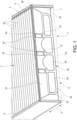
Fig. 1 and2 are perspective views of a filtering element with a handle portion according to the invention, in an inactive position and in a use position, respectively; -
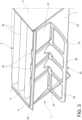
Fig. 3 is another perspective view of the filtering element with the handle portion in the use position; and -
Fig. 4 and 5 are dissected views still showing the handle portion in the inactive position and in the use position. -
Fig. 1 and2 show afiltering element 1 comprising a zigzag-folded filteringweb 2. The filteringelement 1 has a substantially plate-like shape and further comprises twoopposing side bands web 2 and joined thereto. The material of the filtering element may comprise, for example, a nonwoven fabric and may comprise a single layer or several layers coupled together. In the example shown, respective reinforcingside bands side bands - The configuration of the side bands is not however essential for the purposes of the invention. According to alternative embodiments, the reinforcing
side bands side bands web 2 may be absent. - At its opposite ends, the filtering
web 2 comprises two respective end flaps, which delimit the filteringweb 2 in the longitudinal direction. Only one of these end flaps is visible in the figures and is indicated by 7. For the purposes of the present description, "longitudinal direction" means the direction orthogonal to thefolding lines 2a of the filteringweb 2. Theend flap 7 ends with arelevant end edge 7a, extending approximately parallel to thefolding lines 2a. On the opposite side, theend flap 7 is connected to the rest of the filteringweb 2 at one of thefolding lines 2a. -
Fig. 1 also shows schematically, with a dotted line, afilter housing 11 suitable for receiving thefiltering element 1. Thefilter housing 11 may be, for example, a frame or a box, and is configured to allow a flow of fluid, e.g., air, to pass through thefiltering element 1 according to a direction approximately orthogonal to a plane in which thefolding lines 2a lie. - The
filter housing 11 defines aninlet 11a that allows the insertion or the extraction of thefiltering element 1 according to the direction of the arrow A shown inFig. 1 , parallel to the "longitudinal direction" defined above. Theinlet 11a is suitable for being closed by a cover (not shown) which, when thefiltering element 1 is inserted into thefilter housing 11, is positioned opposite to theend flap 7. - As may also be seen in
Fig. 3 to 5 , thefiltering element 1 further comprises asheet element 20 of plastics material superimposed to theend flap 7. Thesheet element 20 comprising abase portion 21 fixed to theend flap 7 and ahandle portion 22 connected to thebase portion 21 by afilm hinge 23. Thefilm hinge 23 extends along a direction parallel to thefolding lines 2a of the filteringweb 2. Thus, thehandle portion 22 of thesheet element 20 is foldable from an inactive position (shown inFig. 1 and4 ), in which thehandle portion 22 is substantially coplanar with thebase portion 21, to a use position (shown inFig. 2 ,3 and5 ), in which thehandle portion 22 is raised relative to thebase portion 21, and to theparticular end flap 7. In other words, in the inactive position thehandle portion 22 rests or is lying on the end flap, while in the use position thehandle portion 22 is substantially upright, forming a certain angle with thebase portion 21, in particular of approximately 90°. - The
sheet element 20 further comprises afastening portion 24 connected to the base portion by anelastic loop 25, in such a way that thesheet element 20 is clipped to theend flap 7 at thefree edge 7a of the flap. In other words, thebase portion 21 and thefastening portion 24 press on opposite faces of the end flap by exerting an elastic retaining force that holds thesheet element 20 on theend flap 7. Theelastic loop 25 of thesheet element 20 is arranged astride thefree edge 7a of theend flap 7. In this manner, thesheet element 20 may be easily press-fitted onto theend flap 7 without requiring the use of additional devices, such as, for example, adhesives. Note that inFig. 1 thefiltering web 2 and especially theend flap 7 are shown as transparent so that thefastening portion 24 of thesheet element 20 is visible. - To facilitate the handling and thus the extraction of the
filtering element 1 from thefilter housing 11, at least onegripping aperture 26 is formed through thehandle portion 22. - As may be seen in particular in
Fig. 4 and 5 , at least onehook projection 27 is made on thehandle portion 22 at thefilm hinge 23. Thehook projection 27 is configured to bite onto theend flap 7 when thehandle portion 22 of thesheet element 20 is in the use position. To this end, thehook projection 27 extends from thehandle portion 22 to beyond the film hinge. When thehandle portion 22 is rotated from the inactive position to the use position, thehook projection 27 thus interferes with a surface of theend flap 7, penetrating into the material of which it is made. This exerts an effective biting action on theend flap 7 that prevents thesheet element 20 from inadvertently slipping off the flap when thehandle portion 22 is pulled to extract the filteringelement 1 out of thefilter housing 11. - An
insert 28 made of elastomeric material is obtained frontally on thebase portion 21 of thesheet element 20. Theinsert 28 extends for a length substantially equal to the width of thefiltering element 1. As may be seen inFig. 5 , theinsert 28 further extends partially into theelastic loop 21 between thebase portion 21 and thefastening portion 24 of thesheet element 20. When theinlet 11a of thefilter housing 11 is closed with a cover, this cover compresses theinsert 28, which acts as a gasket to seal the perimeter of thefiltering element 1 against thefilter housing 11. Furthermore, theinsert 28 prevents noise between the plastics of the filtering element and the particular housing thereof. - It is understood that the invention is not limited to the embodiments described and shown here, but instead may be subject to modifications relating to the shape and arrangement of parts and design and operating details, according to the numerous possible variants that will appear appropriate to those skilled in the art, and which are to be understood as included within the scope of the invention, as defined by the following claims.
Claims (8)
- A filtering element (1) comprisinga zigzag-folded filtering web (2) ending at opposite ends thereof with respective end flaps (7), andopposing side bands (3, 5; 4, 6) joined to the filtering web (2),characterized by further comprising a sheet element (20) of plastics material superimposed to one of the end flaps (7), said sheet element comprising a base portion (21) fixed to the particular end flap (7) and a handle portion (22) connected to the base portion (21) by a film hinge (23) extending along a direction parallel to folding lines (2a) of the filtering web (2), said handle portion being thereby foldable from an inactive position, in which the handle portion (22) is substantially coplanar with the base portion (21), to a use position, in which the handle portion (22) is raised relative to the base portion (21) and to the particular end flap (7).
- The filtering element according to claim 1, wherein the sheet element (20) further comprises a fastening portion (24) connected to the base portion (21) by an elastic loop (25), in such a way that the sheet element (20) is clipped to the particular end flap (7) at an edge (7a) thereof.
- The filtering element according to claim 2, wherein said edge (7a) delimits the particular end flap (7) on a side thereof opposite to one of the folding lines (2a) of the filtering web (2).
- The filtering element according to any of the preceding claims, wherein at least one gripping aperture (26) is formed through the handle portion (22).
- The filtering element according to any of the preceding claims, wherein at least one hook projection (27) is formed on the handle portion (22) at the film hinge (23), said hook projection being configured to bite onto the particular end flap (7) when the handle portion (22) is in the use position.
- The filtering element according to claim 5, wherein the hook projection (27) extends from the handle portion (22) to beyond the film hinge (23).
- The filtering element according to any of the preceding claims, wherein an insert (28) of elastomeric material is formed frontally on the base portion (21).
- The filtering element according to claim 7 in combination with claim 2, wherein the insert (28) partially extends into the elastic loop (25) between the base portion (21) and the fastening portion (24).
Priority Applications (1)
| Application Number | Priority Date | Filing Date | Title |
|---|---|---|---|
| MA64077A MA64077B1 (en) | 2022-02-04 | 2023-02-02 | FILTER ELEMENT WITH HANDLE |
Applications Claiming Priority (1)
| Application Number | Priority Date | Filing Date | Title |
|---|---|---|---|
| IT102022000001976A IT202200001976A1 (en) | 2022-02-04 | 2022-02-04 | Filter element with extraction handle |
Publications (3)
| Publication Number | Publication Date |
|---|---|
| EP4223389A1 EP4223389A1 (en) | 2023-08-09 |
| EP4223389C0 EP4223389C0 (en) | 2024-08-14 |
| EP4223389B1 true EP4223389B1 (en) | 2024-08-14 |
Family
ID=81308432
Family Applications (1)
| Application Number | Title | Priority Date | Filing Date |
|---|---|---|---|
| EP23154612.8A Active EP4223389B1 (en) | 2022-02-04 | 2023-02-02 | Filtering element with extraction handle |
Country Status (4)
| Country | Link |
|---|---|
| EP (1) | EP4223389B1 (en) |
| ES (1) | ES2991729T3 (en) |
| IT (1) | IT202200001976A1 (en) |
| MA (1) | MA64077B1 (en) |
Family Cites Families (6)
| Publication number | Priority date | Publication date | Assignee | Title |
|---|---|---|---|---|
| DE4117550C2 (en) * | 1991-05-29 | 1997-06-12 | Knecht Filterwerke Gmbh | Plate filter made of zigzag folded sheet material |
| JP2002166113A (en) * | 2000-11-29 | 2002-06-11 | Akamatsu Denki Seisakusho:Kk | Dust collection filter |
| FR2911288B1 (en) * | 2007-01-12 | 2009-03-13 | Valeo Materiaux De Friction Sa | METHOD FOR MANUFACTURING AN AIR FILTRATION DEVICE AND DEVICE MANUFACTURED BY SUCH A METHOD |
| DE202008006299U1 (en) * | 2008-05-07 | 2009-09-10 | Mann+Hummel Gmbh | filter element |
| WO2015143326A1 (en) * | 2014-03-21 | 2015-09-24 | 3M Innovative Properties Company | Refillable air filter assembly |
| CN212790189U (en) * | 2020-03-19 | 2021-03-26 | 苏州康冠净化科技有限公司 | Filter element |
-
2022
- 2022-02-04 IT IT102022000001976A patent/IT202200001976A1/en unknown
-
2023
- 2023-02-02 MA MA64077A patent/MA64077B1/en unknown
- 2023-02-02 ES ES23154612T patent/ES2991729T3/en active Active
- 2023-02-02 EP EP23154612.8A patent/EP4223389B1/en active Active
Also Published As
| Publication number | Publication date |
|---|---|
| EP4223389A1 (en) | 2023-08-09 |
| EP4223389C0 (en) | 2024-08-14 |
| ES2991729T3 (en) | 2024-12-04 |
| MA64077B1 (en) | 2024-10-31 |
| IT202200001976A1 (en) | 2023-08-04 |
Similar Documents
| Publication | Publication Date | Title |
|---|---|---|
| US8075658B2 (en) | Filter element | |
| US5554205A (en) | Air filter for the interior of a motor vehicle | |
| US20080047240A1 (en) | Flexible Filter Element | |
| CN102284203B (en) | Assembly with a cover and a self-supporting filter element | |
| US8182570B2 (en) | Compact air filter element | |
| US1125535A (en) | Envelop. | |
| JP5602521B2 (en) | Air filter insert | |
| EP4223389A1 (en) | Filtering element with extraction handle | |
| CN107537246B (en) | Bag filter assembly | |
| CN105517688A (en) | Air filter | |
| JP2003053122A (en) | Filtering system | |
| CN106999827B (en) | Flat filter elements and filter units | |
| EP2319602B1 (en) | Filter assembly for a vehicle heating or air conditioning system, filter unit for this purpose and method for the production of the filter assembly. | |
| JP3693617B2 (en) | filter | |
| CN115944998A (en) | Filtration device, vehicle, use and method | |
| US20060277725A1 (en) | Clip for clipping sheets together | |
| EP3646933B1 (en) | A cover for filtering element | |
| CN113260445A (en) | Foldable filter | |
| JP2010088993A (en) | Air filter | |
| JPH09844A (en) | Device and method for attaching filter to exhaust port | |
| JP3745787B2 (en) | filter | |
| JP2009068427A (en) | Air cleaner for internal combustion engines | |
| JP4474331B2 (en) | Filter cover mounting method and filter device | |
| EP1518715A1 (en) | A paper-clip, particulary for use in motor vehicles | |
| US12208662B2 (en) | Housing for a heating, air-conditioning and/or ventilation device for a motor vehicle |
Legal Events
| Date | Code | Title | Description |
|---|---|---|---|
| PUAI | Public reference made under article 153(3) epc to a published international application that has entered the european phase |
Free format text: ORIGINAL CODE: 0009012 |
|
| STAA | Information on the status of an ep patent application or granted ep patent |
Free format text: STATUS: THE APPLICATION HAS BEEN PUBLISHED |
|
| AK | Designated contracting states |
Kind code of ref document: A1 Designated state(s): AL AT BE BG CH CY CZ DE DK EE ES FI FR GB GR HR HU IE IS IT LI LT LU LV MC ME MK MT NL NO PL PT RO RS SE SI SK SM TR |
|
| STAA | Information on the status of an ep patent application or granted ep patent |
Free format text: STATUS: REQUEST FOR EXAMINATION WAS MADE |
|
| 17P | Request for examination filed |
Effective date: 20240108 |
|
| RAV | Requested validation state of the european patent: fee paid |
Extension state: MA Effective date: 20240108 |
|
| RBV | Designated contracting states (corrected) |
Designated state(s): AL AT BE BG CH CY CZ DE DK EE ES FI FR GB GR HR HU IE IS IT LI LT LU LV MC ME MK MT NL NO PL PT RO RS SE SI SK SM TR |
|
| GRAP | Despatch of communication of intention to grant a patent |
Free format text: ORIGINAL CODE: EPIDOSNIGR1 |
|
| STAA | Information on the status of an ep patent application or granted ep patent |
Free format text: STATUS: GRANT OF PATENT IS INTENDED |
|
| INTG | Intention to grant announced |
Effective date: 20240325 |
|
| GRAS | Grant fee paid |
Free format text: ORIGINAL CODE: EPIDOSNIGR3 |
|
| GRAA | (expected) grant |
Free format text: ORIGINAL CODE: 0009210 |
|
| STAA | Information on the status of an ep patent application or granted ep patent |
Free format text: STATUS: THE PATENT HAS BEEN GRANTED |
|
| AK | Designated contracting states |
Kind code of ref document: B1 Designated state(s): AL AT BE BG CH CY CZ DE DK EE ES FI FR GB GR HR HU IE IS IT LI LT LU LV MC ME MK MT NL NO PL PT RO RS SE SI SK SM TR |
|
| REG | Reference to a national code |
Ref country code: GB Ref legal event code: FG4D |
|
| REG | Reference to a national code |
Ref country code: CH Ref legal event code: EP |
|
| REG | Reference to a national code |
Ref country code: DE Ref legal event code: R096 Ref document number: 602023000361 Country of ref document: DE |
|
| REG | Reference to a national code |
Ref country code: IE Ref legal event code: FG4D |
|
| U01 | Request for unitary effect filed |
Effective date: 20240904 |
|
| U07 | Unitary effect registered |
Designated state(s): AT BE BG DE DK EE FI FR IT LT LU LV MT NL PT RO SE SI Effective date: 20240923 |
|
| REG | Reference to a national code |
Ref country code: MA Ref legal event code: VAGR Ref document number: 64077 Country of ref document: MA Kind code of ref document: B1 |
|
| REG | Reference to a national code |
Ref country code: ES Ref legal event code: FG2A Ref document number: 2991729 Country of ref document: ES Kind code of ref document: T3 Effective date: 20241204 |
|
| PG25 | Lapsed in a contracting state [announced via postgrant information from national office to epo] |
Ref country code: NO Free format text: LAPSE BECAUSE OF FAILURE TO SUBMIT A TRANSLATION OF THE DESCRIPTION OR TO PAY THE FEE WITHIN THE PRESCRIBED TIME-LIMIT Effective date: 20241114 |
|
| PG25 | Lapsed in a contracting state [announced via postgrant information from national office to epo] |
Ref country code: GR Free format text: LAPSE BECAUSE OF FAILURE TO SUBMIT A TRANSLATION OF THE DESCRIPTION OR TO PAY THE FEE WITHIN THE PRESCRIBED TIME-LIMIT Effective date: 20241115 Ref country code: PL Free format text: LAPSE BECAUSE OF FAILURE TO SUBMIT A TRANSLATION OF THE DESCRIPTION OR TO PAY THE FEE WITHIN THE PRESCRIBED TIME-LIMIT Effective date: 20240814 |
|
| PG25 | Lapsed in a contracting state [announced via postgrant information from national office to epo] |
Ref country code: IS Free format text: LAPSE BECAUSE OF FAILURE TO SUBMIT A TRANSLATION OF THE DESCRIPTION OR TO PAY THE FEE WITHIN THE PRESCRIBED TIME-LIMIT Effective date: 20241214 |
|
| PG25 | Lapsed in a contracting state [announced via postgrant information from national office to epo] |
Ref country code: HR Free format text: LAPSE BECAUSE OF FAILURE TO SUBMIT A TRANSLATION OF THE DESCRIPTION OR TO PAY THE FEE WITHIN THE PRESCRIBED TIME-LIMIT Effective date: 20240814 |
|
| PG25 | Lapsed in a contracting state [announced via postgrant information from national office to epo] |
Ref country code: RS Free format text: LAPSE BECAUSE OF FAILURE TO SUBMIT A TRANSLATION OF THE DESCRIPTION OR TO PAY THE FEE WITHIN THE PRESCRIBED TIME-LIMIT Effective date: 20241114 |
|
| PG25 | Lapsed in a contracting state [announced via postgrant information from national office to epo] |
Ref country code: RS Free format text: LAPSE BECAUSE OF FAILURE TO SUBMIT A TRANSLATION OF THE DESCRIPTION OR TO PAY THE FEE WITHIN THE PRESCRIBED TIME-LIMIT Effective date: 20241114 Ref country code: PL Free format text: LAPSE BECAUSE OF FAILURE TO SUBMIT A TRANSLATION OF THE DESCRIPTION OR TO PAY THE FEE WITHIN THE PRESCRIBED TIME-LIMIT Effective date: 20240814 Ref country code: NO Free format text: LAPSE BECAUSE OF FAILURE TO SUBMIT A TRANSLATION OF THE DESCRIPTION OR TO PAY THE FEE WITHIN THE PRESCRIBED TIME-LIMIT Effective date: 20241114 Ref country code: IS Free format text: LAPSE BECAUSE OF FAILURE TO SUBMIT A TRANSLATION OF THE DESCRIPTION OR TO PAY THE FEE WITHIN THE PRESCRIBED TIME-LIMIT Effective date: 20241214 Ref country code: HR Free format text: LAPSE BECAUSE OF FAILURE TO SUBMIT A TRANSLATION OF THE DESCRIPTION OR TO PAY THE FEE WITHIN THE PRESCRIBED TIME-LIMIT Effective date: 20240814 Ref country code: GR Free format text: LAPSE BECAUSE OF FAILURE TO SUBMIT A TRANSLATION OF THE DESCRIPTION OR TO PAY THE FEE WITHIN THE PRESCRIBED TIME-LIMIT Effective date: 20241115 |
|
| U20 | Renewal fee for the european patent with unitary effect paid |
Year of fee payment: 3 Effective date: 20250122 |
|
| PG25 | Lapsed in a contracting state [announced via postgrant information from national office to epo] |
Ref country code: SM Free format text: LAPSE BECAUSE OF FAILURE TO SUBMIT A TRANSLATION OF THE DESCRIPTION OR TO PAY THE FEE WITHIN THE PRESCRIBED TIME-LIMIT Effective date: 20240814 |
|
| PG25 | Lapsed in a contracting state [announced via postgrant information from national office to epo] |
Ref country code: CZ Free format text: LAPSE BECAUSE OF FAILURE TO SUBMIT A TRANSLATION OF THE DESCRIPTION OR TO PAY THE FEE WITHIN THE PRESCRIBED TIME-LIMIT Effective date: 20240814 |
|
| PG25 | Lapsed in a contracting state [announced via postgrant information from national office to epo] |
Ref country code: SK Free format text: LAPSE BECAUSE OF FAILURE TO SUBMIT A TRANSLATION OF THE DESCRIPTION OR TO PAY THE FEE WITHIN THE PRESCRIBED TIME-LIMIT Effective date: 20240814 |
|
| PLBE | No opposition filed within time limit |
Free format text: ORIGINAL CODE: 0009261 |
|
| STAA | Information on the status of an ep patent application or granted ep patent |
Free format text: STATUS: NO OPPOSITION FILED WITHIN TIME LIMIT |
|
| 26N | No opposition filed |
Effective date: 20250515 |
|
| PG25 | Lapsed in a contracting state [announced via postgrant information from national office to epo] |
Ref country code: MC Free format text: LAPSE BECAUSE OF FAILURE TO SUBMIT A TRANSLATION OF THE DESCRIPTION OR TO PAY THE FEE WITHIN THE PRESCRIBED TIME-LIMIT Effective date: 20240814 |
|
| VSFP | Annual fee paid to validation state [announced via postgrant information from national office to epo] |
Ref country code: MA Payment date: 20250203 Year of fee payment: 3 |
|
| PG25 | Lapsed in a contracting state [announced via postgrant information from national office to epo] |
Ref country code: IE Free format text: LAPSE BECAUSE OF NON-PAYMENT OF DUE FEES Effective date: 20250202 |
|
| U20 | Renewal fee for the european patent with unitary effect paid |
Year of fee payment: 4 Effective date: 20251230 |
|
| PGFP | Annual fee paid to national office [announced via postgrant information from national office to epo] |
Ref country code: ES Payment date: 20260302 Year of fee payment: 4 |
|
| VSFP | Annual fee paid to validation state [announced via postgrant information from national office to epo] |
Ref country code: MA Payment date: 20260202 Year of fee payment: 4 |
|
| PGFP | Annual fee paid to national office [announced via postgrant information from national office to epo] |
Ref country code: TR Payment date: 20260202 Year of fee payment: 4 |