EP4223263A1 - Systems and apparatus for treatment of glaucoma - Google Patents
Systems and apparatus for treatment of glaucoma Download PDFInfo
- Publication number
- EP4223263A1 EP4223263A1 EP23164959.1A EP23164959A EP4223263A1 EP 4223263 A1 EP4223263 A1 EP 4223263A1 EP 23164959 A EP23164959 A EP 23164959A EP 4223263 A1 EP4223263 A1 EP 4223263A1
- Authority
- EP
- European Patent Office
- Prior art keywords
- eye
- wedge
- glaucoma drainage
- drainage device
- rod
- Prior art date
- Legal status (The legal status is an assumption and is not a legal conclusion. Google has not performed a legal analysis and makes no representation as to the accuracy of the status listed.)
- Pending
Links
- 208000010412 Glaucoma Diseases 0.000 title claims abstract description 56
- 208000024304 Choroidal Effusions Diseases 0.000 claims abstract description 64
- 210000002159 anterior chamber Anatomy 0.000 claims abstract description 39
- 210000001742 aqueous humor Anatomy 0.000 claims abstract description 18
- -1 styrene ethylene butylene styrene Chemical class 0.000 claims description 19
- 239000000463 material Substances 0.000 claims description 14
- 238000013519 translation Methods 0.000 claims description 8
- 239000004743 Polypropylene Substances 0.000 claims description 5
- 229920001155 polypropylene Polymers 0.000 claims description 5
- 239000004698 Polyethylene Substances 0.000 claims description 4
- 229920000573 polyethylene Polymers 0.000 claims description 4
- 238000002513 implantation Methods 0.000 abstract description 8
- 210000001519 tissue Anatomy 0.000 abstract description 8
- 230000007480 spreading Effects 0.000 abstract description 3
- 238000003892 spreading Methods 0.000 abstract description 3
- 230000035515 penetration Effects 0.000 abstract description 2
- 229920002988 biodegradable polymer Polymers 0.000 description 13
- 239000004621 biodegradable polymer Substances 0.000 description 13
- 239000003814 drug Substances 0.000 description 13
- 239000011159 matrix material Substances 0.000 description 13
- 238000000034 method Methods 0.000 description 13
- 210000003813 thumb Anatomy 0.000 description 13
- 239000007943 implant Substances 0.000 description 12
- 229940124597 therapeutic agent Drugs 0.000 description 11
- 210000003161 choroid Anatomy 0.000 description 8
- 230000004410 intraocular pressure Effects 0.000 description 8
- 210000003786 sclera Anatomy 0.000 description 7
- 229940079593 drug Drugs 0.000 description 5
- 239000012530 fluid Substances 0.000 description 5
- 210000004240 ciliary body Anatomy 0.000 description 4
- 229920001577 copolymer Polymers 0.000 description 4
- 238000005520 cutting process Methods 0.000 description 4
- 239000003112 inhibitor Substances 0.000 description 4
- 238000003780 insertion Methods 0.000 description 4
- 230000037431 insertion Effects 0.000 description 4
- 229920000642 polymer Polymers 0.000 description 4
- 229920002635 polyurethane Polymers 0.000 description 4
- 239000004814 polyurethane Substances 0.000 description 4
- 238000001356 surgical procedure Methods 0.000 description 4
- 210000001585 trabecular meshwork Anatomy 0.000 description 4
- 201000004569 Blindness Diseases 0.000 description 3
- JOYRKODLDBILNP-UHFFFAOYSA-N Ethyl urethane Chemical compound CCOC(N)=O JOYRKODLDBILNP-UHFFFAOYSA-N 0.000 description 3
- 229920000954 Polyglycolide Polymers 0.000 description 3
- 239000005557 antagonist Substances 0.000 description 3
- 239000003795 chemical substances by application Substances 0.000 description 3
- 150000001875 compounds Chemical class 0.000 description 3
- 210000004087 cornea Anatomy 0.000 description 3
- 230000002401 inhibitory effect Effects 0.000 description 3
- 230000033001 locomotion Effects 0.000 description 3
- 229910052751 metal Inorganic materials 0.000 description 3
- 239000002184 metal Substances 0.000 description 3
- 230000037361 pathway Effects 0.000 description 3
- 229920000747 poly(lactic acid) Polymers 0.000 description 3
- YUWPMEXLKGOSBF-GACAOOTBSA-N Anecortave acetate Chemical compound O=C1CC[C@]2(C)C3=CC[C@]4(C)[C@](C(=O)COC(=O)C)(O)CC[C@H]4[C@@H]3CCC2=C1 YUWPMEXLKGOSBF-GACAOOTBSA-N 0.000 description 2
- 208000002177 Cataract Diseases 0.000 description 2
- AOJJSUZBOXZQNB-TZSSRYMLSA-N Doxorubicin Chemical compound O([C@H]1C[C@@](O)(CC=2C(O)=C3C(=O)C=4C=CC=C(C=4C(=O)C3=C(O)C=21)OC)C(=O)CO)[C@H]1C[C@H](N)[C@H](O)[C@H](C)O1 AOJJSUZBOXZQNB-TZSSRYMLSA-N 0.000 description 2
- HTTJABKRGRZYRN-UHFFFAOYSA-N Heparin Chemical compound OC1C(NC(=O)C)C(O)OC(COS(O)(=O)=O)C1OC1C(OS(O)(=O)=O)C(O)C(OC2C(C(OS(O)(=O)=O)C(OC3C(C(O)C(O)C(O3)C(O)=O)OS(O)(=O)=O)C(CO)O2)NS(O)(=O)=O)C(C(O)=O)O1 HTTJABKRGRZYRN-UHFFFAOYSA-N 0.000 description 2
- XEEYBQQBJWHFJM-UHFFFAOYSA-N Iron Chemical compound [Fe] XEEYBQQBJWHFJM-UHFFFAOYSA-N 0.000 description 2
- NWIBSHFKIJFRCO-WUDYKRTCSA-N Mytomycin Chemical compound C1N2C(C(C(C)=C(N)C3=O)=O)=C3[C@@H](COC(N)=O)[C@@]2(OC)[C@@H]2[C@H]1N2 NWIBSHFKIJFRCO-WUDYKRTCSA-N 0.000 description 2
- PXHVJJICTQNCMI-UHFFFAOYSA-N Nickel Chemical compound [Ni] PXHVJJICTQNCMI-UHFFFAOYSA-N 0.000 description 2
- MWUXSHHQAYIFBG-UHFFFAOYSA-N Nitric oxide Chemical compound O=[N] MWUXSHHQAYIFBG-UHFFFAOYSA-N 0.000 description 2
- 229930012538 Paclitaxel Natural products 0.000 description 2
- 239000004952 Polyamide Substances 0.000 description 2
- 239000004642 Polyimide Substances 0.000 description 2
- NKANXQFJJICGDU-QPLCGJKRSA-N Tamoxifen Chemical compound C=1C=CC=CC=1C(/CC)=C(C=1C=CC(OCCN(C)C)=CC=1)/C1=CC=CC=C1 NKANXQFJJICGDU-QPLCGJKRSA-N 0.000 description 2
- RTAQQCXQSZGOHL-UHFFFAOYSA-N Titanium Chemical compound [Ti] RTAQQCXQSZGOHL-UHFFFAOYSA-N 0.000 description 2
- 229960001232 anecortave Drugs 0.000 description 2
- 238000013459 approach Methods 0.000 description 2
- 230000004323 axial length Effects 0.000 description 2
- 239000012620 biological material Substances 0.000 description 2
- 210000004204 blood vessel Anatomy 0.000 description 2
- 239000003246 corticosteroid Substances 0.000 description 2
- 239000000835 fiber Substances 0.000 description 2
- 239000003102 growth factor Substances 0.000 description 2
- 229920000669 heparin Polymers 0.000 description 2
- 229960002897 heparin Drugs 0.000 description 2
- 102000006495 integrins Human genes 0.000 description 2
- 108010044426 integrins Proteins 0.000 description 2
- 230000007246 mechanism Effects 0.000 description 2
- 150000002739 metals Chemical class 0.000 description 2
- 239000000203 mixture Substances 0.000 description 2
- 210000001328 optic nerve Anatomy 0.000 description 2
- 238000012014 optical coherence tomography Methods 0.000 description 2
- 229960001592 paclitaxel Drugs 0.000 description 2
- BASFCYQUMIYNBI-UHFFFAOYSA-N platinum Chemical compound [Pt] BASFCYQUMIYNBI-UHFFFAOYSA-N 0.000 description 2
- 229920002492 poly(sulfone) Polymers 0.000 description 2
- 229920002647 polyamide Polymers 0.000 description 2
- 239000004417 polycarbonate Substances 0.000 description 2
- 229920000515 polycarbonate Polymers 0.000 description 2
- 239000004633 polyglycolic acid Substances 0.000 description 2
- 229920001721 polyimide Polymers 0.000 description 2
- ZAHRKKWIAAJSAO-UHFFFAOYSA-N rapamycin Natural products COCC(O)C(=C/C(C)C(=O)CC(OC(=O)C1CCCCN1C(=O)C(=O)C2(O)OC(CC(OC)C(=CC=CC=CC(C)CC(C)C(=O)C)C)CCC2C)C(C)CC3CCC(O)C(C3)OC)C ZAHRKKWIAAJSAO-UHFFFAOYSA-N 0.000 description 2
- 230000009467 reduction Effects 0.000 description 2
- 229960002930 sirolimus Drugs 0.000 description 2
- QFJCIRLUMZQUOT-HPLJOQBZSA-N sirolimus Chemical compound C1C[C@@H](O)[C@H](OC)C[C@@H]1C[C@@H](C)[C@H]1OC(=O)[C@@H]2CCCCN2C(=O)C(=O)[C@](O)(O2)[C@H](C)CC[C@H]2C[C@H](OC)/C(C)=C/C=C/C=C/[C@@H](C)C[C@@H](C)C(=O)[C@H](OC)[C@H](O)/C(C)=C/[C@@H](C)C(=O)C1 QFJCIRLUMZQUOT-HPLJOQBZSA-N 0.000 description 2
- 239000010935 stainless steel Substances 0.000 description 2
- 229910001220 stainless steel Inorganic materials 0.000 description 2
- RCINICONZNJXQF-MZXODVADSA-N taxol Chemical compound O([C@@H]1[C@@]2(C[C@@H](C(C)=C(C2(C)C)[C@H](C([C@]2(C)[C@@H](O)C[C@H]3OC[C@]3([C@H]21)OC(C)=O)=O)OC(=O)C)OC(=O)[C@H](O)[C@@H](NC(=O)C=1C=CC=CC=1)C=1C=CC=CC=1)O)C(=O)C1=CC=CC=C1 RCINICONZNJXQF-MZXODVADSA-N 0.000 description 2
- 229910052719 titanium Inorganic materials 0.000 description 2
- 239000010936 titanium Substances 0.000 description 2
- KIUKXJAPPMFGSW-DNGZLQJQSA-N (2S,3S,4S,5R,6R)-6-[(2S,3R,4R,5S,6R)-3-Acetamido-2-[(2S,3S,4R,5R,6R)-6-[(2R,3R,4R,5S,6R)-3-acetamido-2,5-dihydroxy-6-(hydroxymethyl)oxan-4-yl]oxy-2-carboxy-4,5-dihydroxyoxan-3-yl]oxy-5-hydroxy-6-(hydroxymethyl)oxan-4-yl]oxy-3,4,5-trihydroxyoxane-2-carboxylic acid Chemical compound CC(=O)N[C@H]1[C@H](O)O[C@H](CO)[C@@H](O)[C@@H]1O[C@H]1[C@H](O)[C@@H](O)[C@H](O[C@H]2[C@@H]([C@@H](O[C@H]3[C@@H]([C@@H](O)[C@H](O)[C@H](O3)C(O)=O)O)[C@H](O)[C@@H](CO)O2)NC(C)=O)[C@@H](C(O)=O)O1 KIUKXJAPPMFGSW-DNGZLQJQSA-N 0.000 description 1
- 101710175516 14 kDa zinc-binding protein Proteins 0.000 description 1
- CQOQDQWUFQDJMK-SSTWWWIQSA-N 2-methoxy-17beta-estradiol Chemical compound C([C@@H]12)C[C@]3(C)[C@@H](O)CC[C@H]3[C@@H]1CCC1=C2C=C(OC)C(O)=C1 CQOQDQWUFQDJMK-SSTWWWIQSA-N 0.000 description 1
- WLCZTRVUXYALDD-IBGZPJMESA-N 7-[[(2s)-2,6-bis(2-methoxyethoxycarbonylamino)hexanoyl]amino]heptoxy-methylphosphinic acid Chemical compound COCCOC(=O)NCCCC[C@H](NC(=O)OCCOC)C(=O)NCCCCCCCOP(C)(O)=O WLCZTRVUXYALDD-IBGZPJMESA-N 0.000 description 1
- 102400000068 Angiostatin Human genes 0.000 description 1
- 108010079709 Angiostatins Proteins 0.000 description 1
- 108020000948 Antisense Oligonucleotides Proteins 0.000 description 1
- 102100040214 Apolipoprotein(a) Human genes 0.000 description 1
- 108010012927 Apoprotein(a) Proteins 0.000 description 1
- 108091023037 Aptamer Proteins 0.000 description 1
- 241000283690 Bos taurus Species 0.000 description 1
- 229920002101 Chitin Polymers 0.000 description 1
- 108010035532 Collagen Proteins 0.000 description 1
- 102000008186 Collagen Human genes 0.000 description 1
- HVXBOLULGPECHP-WAYWQWQTSA-N Combretastatin A4 Chemical compound C1=C(O)C(OC)=CC=C1\C=C/C1=CC(OC)=C(OC)C(OC)=C1 HVXBOLULGPECHP-WAYWQWQTSA-N 0.000 description 1
- 102000004127 Cytokines Human genes 0.000 description 1
- 108090000695 Cytokines Proteins 0.000 description 1
- 102000004163 DNA-directed RNA polymerases Human genes 0.000 description 1
- 108090000626 DNA-directed RNA polymerases Proteins 0.000 description 1
- 229920002307 Dextran Polymers 0.000 description 1
- 102400001047 Endostatin Human genes 0.000 description 1
- 108010079505 Endostatins Proteins 0.000 description 1
- 108050009340 Endothelin Proteins 0.000 description 1
- 102000002045 Endothelin Human genes 0.000 description 1
- 102000004190 Enzymes Human genes 0.000 description 1
- 108090000790 Enzymes Proteins 0.000 description 1
- 241000283073 Equus caballus Species 0.000 description 1
- HKVAMNSJSFKALM-GKUWKFKPSA-N Everolimus Chemical compound C1C[C@@H](OCCO)[C@H](OC)C[C@@H]1C[C@@H](C)[C@H]1OC(=O)[C@@H]2CCCCN2C(=O)C(=O)[C@](O)(O2)[C@H](C)CC[C@H]2C[C@H](OC)/C(C)=C/C=C/C=C/[C@@H](C)C[C@@H](C)C(=O)[C@H](OC)[C@H](O)/C(C)=C/[C@@H](C)C(=O)C1 HKVAMNSJSFKALM-GKUWKFKPSA-N 0.000 description 1
- 241000282324 Felis Species 0.000 description 1
- 206010016654 Fibrosis Diseases 0.000 description 1
- GHASVSINZRGABV-UHFFFAOYSA-N Fluorouracil Chemical compound FC1=CNC(=O)NC1=O GHASVSINZRGABV-UHFFFAOYSA-N 0.000 description 1
- 108010010803 Gelatin Proteins 0.000 description 1
- 102000003886 Glycoproteins Human genes 0.000 description 1
- 108090000288 Glycoproteins Proteins 0.000 description 1
- 229920002683 Glycosaminoglycan Polymers 0.000 description 1
- 108010078321 Guanylate Cyclase Proteins 0.000 description 1
- 102000014469 Guanylate cyclase Human genes 0.000 description 1
- DGAQECJNVWCQMB-PUAWFVPOSA-M Ilexoside XXIX Chemical compound C[C@@H]1CC[C@@]2(CC[C@@]3(C(=CC[C@H]4[C@]3(CC[C@@H]5[C@@]4(CC[C@@H](C5(C)C)OS(=O)(=O)[O-])C)C)[C@@H]2[C@]1(C)O)C)C(=O)O[C@H]6[C@@H]([C@H]([C@@H]([C@H](O6)CO)O)O)O.[Na+] DGAQECJNVWCQMB-PUAWFVPOSA-M 0.000 description 1
- 102100034343 Integrase Human genes 0.000 description 1
- 108010002352 Interleukin-1 Proteins 0.000 description 1
- 108010063738 Interleukins Proteins 0.000 description 1
- 102000015696 Interleukins Human genes 0.000 description 1
- SHGAZHPCJJPHSC-NUEINMDLSA-N Isotretinoin Chemical compound OC(=O)C=C(C)/C=C/C=C(C)C=CC1=C(C)CCCC1(C)C SHGAZHPCJJPHSC-NUEINMDLSA-N 0.000 description 1
- FBOZXECLQNJBKD-ZDUSSCGKSA-N L-methotrexate Chemical compound C=1N=C2N=C(N)N=C(N)C2=NC=1CN(C)C1=CC=C(C(=O)N[C@@H](CCC(O)=O)C(O)=O)C=C1 FBOZXECLQNJBKD-ZDUSSCGKSA-N 0.000 description 1
- OUYCCCASQSFEME-QMMMGPOBSA-N L-tyrosine Chemical compound OC(=O)[C@@H](N)CC1=CC=C(O)C=C1 OUYCCCASQSFEME-QMMMGPOBSA-N 0.000 description 1
- 108010033266 Lipoprotein(a) Proteins 0.000 description 1
- 102000057248 Lipoprotein(a) Human genes 0.000 description 1
- PCZOHLXUXFIOCF-UHFFFAOYSA-N Monacolin X Natural products C12C(OC(=O)C(C)CC)CC(C)C=C2C=CC(C)C1CCC1CC(O)CC(=O)O1 PCZOHLXUXFIOCF-UHFFFAOYSA-N 0.000 description 1
- ZDZOTLJHXYCWBA-VCVYQWHSSA-N N-debenzoyl-N-(tert-butoxycarbonyl)-10-deacetyltaxol Chemical compound O([C@H]1[C@H]2[C@@](C([C@H](O)C3=C(C)[C@@H](OC(=O)[C@H](O)[C@@H](NC(=O)OC(C)(C)C)C=4C=CC=CC=4)C[C@]1(O)C3(C)C)=O)(C)[C@@H](O)C[C@H]1OC[C@]12OC(=O)C)C(=O)C1=CC=CC=C1 ZDZOTLJHXYCWBA-VCVYQWHSSA-N 0.000 description 1
- 208000028389 Nerve injury Diseases 0.000 description 1
- SNIOPGDIGTZGOP-UHFFFAOYSA-N Nitroglycerin Chemical compound [O-][N+](=O)OCC(O[N+]([O-])=O)CO[N+]([O-])=O SNIOPGDIGTZGOP-UHFFFAOYSA-N 0.000 description 1
- 239000000006 Nitroglycerin Substances 0.000 description 1
- 206010030348 Open-Angle Glaucoma Diseases 0.000 description 1
- 229920003171 Poly (ethylene oxide) Polymers 0.000 description 1
- 239000004696 Poly ether ether ketone Substances 0.000 description 1
- 229920002367 Polyisobutene Polymers 0.000 description 1
- 239000004721 Polyphenylene oxide Substances 0.000 description 1
- 229940123924 Protein kinase C inhibitor Drugs 0.000 description 1
- 102000016611 Proteoglycans Human genes 0.000 description 1
- 108010067787 Proteoglycans Proteins 0.000 description 1
- 108010092799 RNA-directed DNA polymerase Proteins 0.000 description 1
- UIRKNQLZZXALBI-MSVGPLKSSA-N Squalamine Chemical compound C([C@@H]1C[C@H]2O)[C@@H](NCCCNCCCCN)CC[C@]1(C)[C@@H]1[C@@H]2[C@@H]2CC[C@H]([C@H](C)CC[C@H](C(C)C)OS(O)(=O)=O)[C@@]2(C)CC1 UIRKNQLZZXALBI-MSVGPLKSSA-N 0.000 description 1
- UIRKNQLZZXALBI-UHFFFAOYSA-N Squalamine Natural products OC1CC2CC(NCCCNCCCCN)CCC2(C)C2C1C1CCC(C(C)CCC(C(C)C)OS(O)(=O)=O)C1(C)CC2 UIRKNQLZZXALBI-UHFFFAOYSA-N 0.000 description 1
- 102000019197 Superoxide Dismutase Human genes 0.000 description 1
- 108010012715 Superoxide dismutase Proteins 0.000 description 1
- 102000004887 Transforming Growth Factor beta Human genes 0.000 description 1
- 108090001012 Transforming Growth Factor beta Proteins 0.000 description 1
- 102400001320 Transforming growth factor alpha Human genes 0.000 description 1
- 101800004564 Transforming growth factor alpha Proteins 0.000 description 1
- GSNOZLZNQMLSKJ-UHFFFAOYSA-N Trapidil Chemical compound CCN(CC)C1=CC(C)=NC2=NC=NN12 GSNOZLZNQMLSKJ-UHFFFAOYSA-N 0.000 description 1
- 108060008682 Tumor Necrosis Factor Proteins 0.000 description 1
- 102000007537 Type II DNA Topoisomerases Human genes 0.000 description 1
- 108010046308 Type II DNA Topoisomerases Proteins 0.000 description 1
- 102000016548 Vascular Endothelial Growth Factor Receptor-1 Human genes 0.000 description 1
- 108010053096 Vascular Endothelial Growth Factor Receptor-1 Proteins 0.000 description 1
- 102000005789 Vascular Endothelial Growth Factors Human genes 0.000 description 1
- 108010019530 Vascular Endothelial Growth Factors Proteins 0.000 description 1
- 229920000122 acrylonitrile butadiene styrene Polymers 0.000 description 1
- 239000004676 acrylonitrile butadiene styrene Substances 0.000 description 1
- 230000004913 activation Effects 0.000 description 1
- 239000004480 active ingredient Substances 0.000 description 1
- 229940009456 adriamycin Drugs 0.000 description 1
- 239000000556 agonist Substances 0.000 description 1
- 229930013930 alkaloid Natural products 0.000 description 1
- 239000000956 alloy Substances 0.000 description 1
- 229910045601 alloy Inorganic materials 0.000 description 1
- 229910052782 aluminium Inorganic materials 0.000 description 1
- XAGFODPZIPBFFR-UHFFFAOYSA-N aluminium Chemical compound [Al] XAGFODPZIPBFFR-UHFFFAOYSA-N 0.000 description 1
- 229950010817 alvocidib Drugs 0.000 description 1
- BIIVYFLTOXDAOV-YVEFUNNKSA-N alvocidib Chemical compound O[C@@H]1CN(C)CC[C@@H]1C1=C(O)C=C(O)C2=C1OC(C=1C(=CC=CC=1)Cl)=CC2=O BIIVYFLTOXDAOV-YVEFUNNKSA-N 0.000 description 1
- 239000004037 angiogenesis inhibitor Substances 0.000 description 1
- 229940121369 angiogenesis inhibitor Drugs 0.000 description 1
- 239000002333 angiotensin II receptor antagonist Substances 0.000 description 1
- 230000001028 anti-proliverative effect Effects 0.000 description 1
- 229940045988 antineoplastic drug protein kinase inhibitors Drugs 0.000 description 1
- 239000000074 antisense oligonucleotide Substances 0.000 description 1
- 238000012230 antisense oligonucleotides Methods 0.000 description 1
- FZCSTZYAHCUGEM-UHFFFAOYSA-N aspergillomarasmine B Natural products OC(=O)CNC(C(O)=O)CNC(C(O)=O)CC(O)=O FZCSTZYAHCUGEM-UHFFFAOYSA-N 0.000 description 1
- JUPQTSLXMOCDHR-UHFFFAOYSA-N benzene-1,4-diol;bis(4-fluorophenyl)methanone Chemical compound OC1=CC=C(O)C=C1.C1=CC(F)=CC=C1C(=O)C1=CC=C(F)C=C1 JUPQTSLXMOCDHR-UHFFFAOYSA-N 0.000 description 1
- 239000000560 biocompatible material Substances 0.000 description 1
- 230000015572 biosynthetic process Effects 0.000 description 1
- 230000015556 catabolic process Effects 0.000 description 1
- 210000004027 cell Anatomy 0.000 description 1
- 230000032823 cell division Effects 0.000 description 1
- 230000012292 cell migration Effects 0.000 description 1
- 230000004663 cell proliferation Effects 0.000 description 1
- 230000001413 cellular effect Effects 0.000 description 1
- 230000005754 cellular signaling Effects 0.000 description 1
- 229960005110 cerivastatin Drugs 0.000 description 1
- SEERZIQQUAZTOL-ANMDKAQQSA-N cerivastatin Chemical compound COCC1=C(C(C)C)N=C(C(C)C)C(\C=C\[C@@H](O)C[C@@H](O)CC(O)=O)=C1C1=CC=C(F)C=C1 SEERZIQQUAZTOL-ANMDKAQQSA-N 0.000 description 1
- 230000001886 ciliary effect Effects 0.000 description 1
- 238000003776 cleavage reaction Methods 0.000 description 1
- 229920001436 collagen Polymers 0.000 description 1
- 229960005537 combretastatin A-4 Drugs 0.000 description 1
- HVXBOLULGPECHP-UHFFFAOYSA-N combretastatin A4 Natural products C1=C(O)C(OC)=CC=C1C=CC1=CC(OC)=C(OC)C(OC)=C1 HVXBOLULGPECHP-UHFFFAOYSA-N 0.000 description 1
- 230000002860 competitive effect Effects 0.000 description 1
- 239000002131 composite material Substances 0.000 description 1
- 210000000795 conjunctiva Anatomy 0.000 description 1
- 229960001334 corticosteroids Drugs 0.000 description 1
- 238000006731 degradation reaction Methods 0.000 description 1
- 229960003957 dexamethasone Drugs 0.000 description 1
- UREBDLICKHMUKA-CXSFZGCWSA-N dexamethasone Chemical compound C1CC2=CC(=O)C=C[C@]2(C)[C@]2(F)[C@@H]1[C@@H]1C[C@@H](C)[C@@](C(=O)CO)(O)[C@@]1(C)C[C@@H]2O UREBDLICKHMUKA-CXSFZGCWSA-N 0.000 description 1
- 239000004205 dimethyl polysiloxane Substances 0.000 description 1
- ZUBDGKVDJUIMQQ-UBFCDGJISA-N endothelin-1 Chemical compound C([C@@H](C(=O)N[C@@H](CC(C)C)C(=O)N[C@@H](CC(O)=O)C(=O)N[C@@H]([C@@H](C)CC)C(=O)N[C@@H]([C@@H](C)CC)C(=O)N[C@@H](CC=1C2=CC=CC=C2NC=1)C(O)=O)NC(=O)[C@H]1NC(=O)[C@H](CC=2C=CC=CC=2)NC(=O)[C@@H](CC=2C=CC(O)=CC=2)NC(=O)[C@H](C(C)C)NC(=O)[C@H]2CSSC[C@@H](C(N[C@H](CO)C(=O)N[C@@H](CO)C(=O)N[C@H](CC(C)C)C(=O)N[C@@H](CCSC)C(=O)N[C@H](CC(O)=O)C(=O)N[C@@H](CCCCN)C(=O)N[C@@H](CCC(O)=O)C(=O)N2)=O)NC(=O)[C@@H](CO)NC(=O)[C@H](N)CSSC1)C1=CNC=N1 ZUBDGKVDJUIMQQ-UBFCDGJISA-N 0.000 description 1
- HKSZLNNOFSGOKW-UHFFFAOYSA-N ent-staurosporine Natural products C12=C3N4C5=CC=CC=C5C3=C3CNC(=O)C3=C2C2=CC=CC=C2N1C1CC(NC)C(OC)C4(C)O1 HKSZLNNOFSGOKW-UHFFFAOYSA-N 0.000 description 1
- 229940088598 enzyme Drugs 0.000 description 1
- 229960005167 everolimus Drugs 0.000 description 1
- 108010036236 extracellular matrix receptor Proteins 0.000 description 1
- 238000001125 extrusion Methods 0.000 description 1
- 230000004761 fibrosis Effects 0.000 description 1
- 229920002313 fluoropolymer Polymers 0.000 description 1
- 229960002949 fluorouracil Drugs 0.000 description 1
- 229920000159 gelatin Polymers 0.000 description 1
- 239000008273 gelatin Substances 0.000 description 1
- 235000019322 gelatine Nutrition 0.000 description 1
- 235000011852 gelatine desserts Nutrition 0.000 description 1
- 150000004676 glycans Chemical class 0.000 description 1
- 229960003711 glyceryl trinitrate Drugs 0.000 description 1
- PCHJSUWPFVWCPO-UHFFFAOYSA-N gold Chemical compound [Au] PCHJSUWPFVWCPO-UHFFFAOYSA-N 0.000 description 1
- 239000010931 gold Substances 0.000 description 1
- 229910052737 gold Inorganic materials 0.000 description 1
- 229920002674 hyaluronan Polymers 0.000 description 1
- 229960003160 hyaluronic acid Drugs 0.000 description 1
- 238000001727 in vivo Methods 0.000 description 1
- 230000000415 inactivating effect Effects 0.000 description 1
- 238000007373 indentation Methods 0.000 description 1
- 229940047122 interleukins Drugs 0.000 description 1
- 230000000968 intestinal effect Effects 0.000 description 1
- 229910052742 iron Inorganic materials 0.000 description 1
- 229960005280 isotretinoin Drugs 0.000 description 1
- 210000000265 leukocyte Anatomy 0.000 description 1
- 229960004844 lovastatin Drugs 0.000 description 1
- PCZOHLXUXFIOCF-BXMDZJJMSA-N lovastatin Chemical compound C([C@H]1[C@@H](C)C=CC2=C[C@H](C)C[C@@H]([C@H]12)OC(=O)[C@@H](C)CC)C[C@@H]1C[C@@H](O)CC(=O)O1 PCZOHLXUXFIOCF-BXMDZJJMSA-N 0.000 description 1
- QLJODMDSTUBWDW-UHFFFAOYSA-N lovastatin hydroxy acid Natural products C1=CC(C)C(CCC(O)CC(O)CC(O)=O)C2C(OC(=O)C(C)CC)CC(C)C=C21 QLJODMDSTUBWDW-UHFFFAOYSA-N 0.000 description 1
- 229940076783 lucentis Drugs 0.000 description 1
- 229940092110 macugen Drugs 0.000 description 1
- 238000004519 manufacturing process Methods 0.000 description 1
- 108020004999 messenger RNA Proteins 0.000 description 1
- 229960000485 methotrexate Drugs 0.000 description 1
- 229920000609 methyl cellulose Polymers 0.000 description 1
- 239000001923 methylcellulose Substances 0.000 description 1
- 235000010981 methylcellulose Nutrition 0.000 description 1
- 230000005012 migration Effects 0.000 description 1
- 238000013508 migration Methods 0.000 description 1
- 229960004857 mitomycin Drugs 0.000 description 1
- 238000012986 modification Methods 0.000 description 1
- 230000004048 modification Effects 0.000 description 1
- 210000003205 muscle Anatomy 0.000 description 1
- 230000008764 nerve damage Effects 0.000 description 1
- 229910052759 nickel Inorganic materials 0.000 description 1
- 230000036963 noncompetitive effect Effects 0.000 description 1
- 229940094443 oxytocics prostaglandins Drugs 0.000 description 1
- 239000001814 pectin Substances 0.000 description 1
- 229920001277 pectin Polymers 0.000 description 1
- 235000010987 pectin Nutrition 0.000 description 1
- 210000003668 pericyte Anatomy 0.000 description 1
- 229940012957 plasmin Drugs 0.000 description 1
- 229910052697 platinum Inorganic materials 0.000 description 1
- 229920000435 poly(dimethylsiloxane) Polymers 0.000 description 1
- 229920003229 poly(methyl methacrylate) Polymers 0.000 description 1
- 229920002463 poly(p-dioxanone) polymer Polymers 0.000 description 1
- 229920000058 polyacrylate Polymers 0.000 description 1
- 229920001748 polybutylene Polymers 0.000 description 1
- 229920001610 polycaprolactone Polymers 0.000 description 1
- 229920001692 polycarbonate urethane Polymers 0.000 description 1
- 239000000622 polydioxanone Substances 0.000 description 1
- 229920000570 polyether Polymers 0.000 description 1
- 229920002530 polyetherether ketone Polymers 0.000 description 1
- 229920000223 polyglycerol Polymers 0.000 description 1
- 239000004926 polymethyl methacrylate Substances 0.000 description 1
- 229920000098 polyolefin Polymers 0.000 description 1
- 229920001282 polysaccharide Polymers 0.000 description 1
- 239000005017 polysaccharide Substances 0.000 description 1
- 229940002612 prodrug Drugs 0.000 description 1
- 239000000651 prodrug Substances 0.000 description 1
- 230000035755 proliferation Effects 0.000 description 1
- 150000003180 prostaglandins Chemical class 0.000 description 1
- 239000003881 protein kinase C inhibitor Substances 0.000 description 1
- 239000003909 protein kinase inhibitor Substances 0.000 description 1
- 108020003175 receptors Proteins 0.000 description 1
- 102000005962 receptors Human genes 0.000 description 1
- 230000002829 reductive effect Effects 0.000 description 1
- 230000010076 replication Effects 0.000 description 1
- 230000007017 scission Effects 0.000 description 1
- 229940116351 sebacate Drugs 0.000 description 1
- CXMXRPHRNRROMY-UHFFFAOYSA-L sebacate(2-) Chemical compound [O-]C(=O)CCCCCCCCC([O-])=O CXMXRPHRNRROMY-UHFFFAOYSA-L 0.000 description 1
- 229920002379 silicone rubber Polymers 0.000 description 1
- 239000004945 silicone rubber Substances 0.000 description 1
- 229910052708 sodium Inorganic materials 0.000 description 1
- 239000011734 sodium Substances 0.000 description 1
- 229950001248 squalamine Drugs 0.000 description 1
- HKSZLNNOFSGOKW-FYTWVXJKSA-N staurosporine Chemical compound C12=C3N4C5=CC=CC=C5C3=C3CNC(=O)C3=C2C2=CC=CC=C2N1[C@H]1C[C@@H](NC)[C@@H](OC)[C@]4(C)O1 HKSZLNNOFSGOKW-FYTWVXJKSA-N 0.000 description 1
- FIAFUQMPZJWCLV-UHFFFAOYSA-N suramin Chemical compound OS(=O)(=O)C1=CC(S(O)(=O)=O)=C2C(NC(=O)C3=CC=C(C(=C3)NC(=O)C=3C=C(NC(=O)NC=4C=C(C=CC=4)C(=O)NC=4C(=CC=C(C=4)C(=O)NC=4C5=C(C=C(C=C5C(=CC=4)S(O)(=O)=O)S(O)(=O)=O)S(O)(=O)=O)C)C=CC=3)C)=CC=C(S(O)(=O)=O)C2=C1 FIAFUQMPZJWCLV-UHFFFAOYSA-N 0.000 description 1
- 229960005314 suramin Drugs 0.000 description 1
- 229960001603 tamoxifen Drugs 0.000 description 1
- RCINICONZNJXQF-XAZOAEDWSA-N taxol® Chemical compound O([C@@H]1[C@@]2(CC(C(C)=C(C2(C)C)[C@H](C([C@]2(C)[C@@H](O)C[C@H]3OC[C@]3(C21)OC(C)=O)=O)OC(=O)C)OC(=O)[C@H](O)[C@@H](NC(=O)C=1C=CC=CC=1)C=1C=CC=CC=1)O)C(=O)C1=CC=CC=C1 RCINICONZNJXQF-XAZOAEDWSA-N 0.000 description 1
- 229940063683 taxotere Drugs 0.000 description 1
- 210000004876 tela submucosa Anatomy 0.000 description 1
- 210000001760 tenon capsule Anatomy 0.000 description 1
- ZRKFYGHZFMAOKI-QMGMOQQFSA-N tgfbeta Chemical compound C([C@H](NC(=O)[C@H](C(C)C)NC(=O)CNC(=O)[C@H](CCC(O)=O)NC(=O)[C@H](CCCNC(N)=N)NC(=O)[C@H](CC(N)=O)NC(=O)[C@H](CC(C)C)NC(=O)[C@H]([C@@H](C)O)NC(=O)[C@H](CCC(O)=O)NC(=O)[C@H]([C@@H](C)O)NC(=O)[C@H](CC(C)C)NC(=O)CNC(=O)[C@H](C)NC(=O)[C@H](CO)NC(=O)[C@H](CCC(N)=O)NC(=O)[C@@H](NC(=O)[C@H](C)NC(=O)[C@H](C)NC(=O)[C@@H](NC(=O)[C@H](CC(C)C)NC(=O)[C@@H](N)CCSC)C(C)C)[C@@H](C)CC)C(=O)N[C@@H]([C@@H](C)O)C(=O)N[C@@H](C(C)C)C(=O)N[C@@H](CC=1C=CC=CC=1)C(=O)N[C@@H](C)C(=O)N1[C@@H](CCC1)C(=O)N[C@@H]([C@@H](C)O)C(=O)N[C@@H](CC(N)=O)C(=O)N[C@@H](CCC(O)=O)C(=O)N[C@@H](C)C(=O)N[C@@H](CC=1C=CC=CC=1)C(=O)N[C@@H](CCCNC(N)=N)C(=O)N[C@@H](C)C(=O)N[C@@H](CC(C)C)C(=O)N1[C@@H](CCC1)C(=O)N1[C@@H](CCC1)C(=O)N[C@@H](CCCNC(N)=N)C(=O)N[C@@H](CCC(O)=O)C(=O)N[C@@H](CCCNC(N)=N)C(=O)N[C@@H](CO)C(=O)N[C@@H](CCCNC(N)=N)C(=O)N[C@@H](CC(C)C)C(=O)N[C@@H](CC(C)C)C(O)=O)C1=CC=C(O)C=C1 ZRKFYGHZFMAOKI-QMGMOQQFSA-N 0.000 description 1
- 239000003053 toxin Substances 0.000 description 1
- 231100000765 toxin Toxicity 0.000 description 1
- 108700012359 toxins Proteins 0.000 description 1
- 229960000363 trapidil Drugs 0.000 description 1
- 229960002117 triamcinolone acetonide Drugs 0.000 description 1
- YNDXUCZADRHECN-JNQJZLCISA-N triamcinolone acetonide Chemical compound C1CC2=CC(=O)C=C[C@]2(C)[C@]2(F)[C@@H]1[C@@H]1C[C@H]3OC(C)(C)O[C@@]3(C(=O)CO)[C@@]1(C)C[C@@H]2O YNDXUCZADRHECN-JNQJZLCISA-N 0.000 description 1
- YWBFPKPWMSWWEA-UHFFFAOYSA-O triazolopyrimidine Chemical compound BrC1=CC=CC(C=2N=C3N=CN[N+]3=C(NCC=3C=CN=CC=3)C=2)=C1 YWBFPKPWMSWWEA-UHFFFAOYSA-O 0.000 description 1
- 102000003390 tumor necrosis factor Human genes 0.000 description 1
- OUYCCCASQSFEME-UHFFFAOYSA-N tyrosine Natural products OC(=O)C(N)CC1=CC=C(O)C=C1 OUYCCCASQSFEME-UHFFFAOYSA-N 0.000 description 1
- 239000002525 vasculotropin inhibitor Substances 0.000 description 1
- 210000003462 vein Anatomy 0.000 description 1
- YTZALCGQUPRCGW-ZSFNYQMMSA-N verteporfin Chemical compound N1C(C=C2C(=C(CCC(O)=O)C(C=C3C(CCC(=O)OC)=C(C)C(N3)=C3)=N2)C)=C(C=C)C(C)=C1C=C1C2=CC=C(C(=O)OC)[C@@H](C(=O)OC)[C@@]2(C)C3=N1 YTZALCGQUPRCGW-ZSFNYQMMSA-N 0.000 description 1
- 239000003190 viscoelastic substance Substances 0.000 description 1
- 230000004393 visual impairment Effects 0.000 description 1
- 229940061392 visudyne Drugs 0.000 description 1
- PAPBSGBWRJIAAV-UHFFFAOYSA-N ε-Caprolactone Chemical compound O=C1CCCCCO1 PAPBSGBWRJIAAV-UHFFFAOYSA-N 0.000 description 1
Images


Classifications
-
- A—HUMAN NECESSITIES
- A61—MEDICAL OR VETERINARY SCIENCE; HYGIENE
- A61F—FILTERS IMPLANTABLE INTO BLOOD VESSELS; PROSTHESES; DEVICES PROVIDING PATENCY TO, OR PREVENTING COLLAPSING OF, TUBULAR STRUCTURES OF THE BODY, e.g. STENTS; ORTHOPAEDIC, NURSING OR CONTRACEPTIVE DEVICES; FOMENTATION; TREATMENT OR PROTECTION OF EYES OR EARS; BANDAGES, DRESSINGS OR ABSORBENT PADS; FIRST-AID KITS
- A61F9/00—Methods or devices for treatment of the eyes; Devices for putting-in contact lenses; Devices to correct squinting; Apparatus to guide the blind; Protective devices for the eyes, carried on the body or in the hand
- A61F9/007—Methods or devices for eye surgery
- A61F9/00781—Apparatus for modifying intraocular pressure, e.g. for glaucoma treatment
-
- A—HUMAN NECESSITIES
- A61—MEDICAL OR VETERINARY SCIENCE; HYGIENE
- A61F—FILTERS IMPLANTABLE INTO BLOOD VESSELS; PROSTHESES; DEVICES PROVIDING PATENCY TO, OR PREVENTING COLLAPSING OF, TUBULAR STRUCTURES OF THE BODY, e.g. STENTS; ORTHOPAEDIC, NURSING OR CONTRACEPTIVE DEVICES; FOMENTATION; TREATMENT OR PROTECTION OF EYES OR EARS; BANDAGES, DRESSINGS OR ABSORBENT PADS; FIRST-AID KITS
- A61F2220/00—Fixations or connections for prostheses classified in groups A61F2/00 - A61F2/26 or A61F2/82 or A61F9/00 or A61F11/00 or subgroups thereof
- A61F2220/0008—Fixation appliances for connecting prostheses to the body
- A61F2220/0016—Fixation appliances for connecting prostheses to the body with sharp anchoring protrusions, e.g. barbs, pins, spikes
Definitions
- the present disclosure relates to the treatment of glaucoma, and more particularly, to medical devices and methods for creating a drainage pathway to divert aqueous humor out of the anterior chamber of the eye such that pressure within the eye is reduced.
- Aqueous humor is produced by the eye's ciliary body and flows from the ciliary body into the anterior chamber, out through a spongy tissue at the front of the eye called the trabecular meshwork and into a drainage canal.
- continuous drainage of aqueous humor keeps intraocular pressure at a normal level.
- proper circulation of aqueous humor is disrupted, causing the level of intraocular pressure to be elevated.
- fluid does not flow freely through the trabecular meshwork, causing an increase in intraocular pressure, damage to the optic nerve and vision loss. Reduction of intraocular pressure is a means of stopping the progression of optic nerve damage, which if untreated can lead to blindness.
- the suprachoroidal space is a space in the eye that lies between the sclera and the choroid. It is known that aqueous humor in the suprachoroidal space can drain therefrom and cause a reduction in intraocular pressure. Although it is not well understood where aqueous humor drains to once it reaches the suprachoroidal space, there are references to aqueous humor draining into the choroid vessels as well as into the venous plexus of the sclera and to the episcleral veins.
- CyPass ® Microstent that includes a tubular body with an internal lumen that drains aqueous humor from the anterior chamber of the eye into the suprachoroidal space of the eye to lower intraocular pressure in the eye.
- a device for implantation into the suprachoroidal space of the eye to promote drainage of aqueous humor from the anterior chamber of the eye to the suprachoroidal space of the eye in order to reduce intraocular pressure.
- the device may be made from a flexible, bio-inert, and biocompatible material that can be inserted into the suprachoroidal space of the eye using an ab interno approach, conform to the curvature of the tissue surrounding the suprachoroidal space (i.e., the sclera and the choroid), and remain in place for a long period of time.
- the device includes an elongated body extending axially from a distal end to a proximal end.
- the distal end of elongate body forms a wedge with a leading distal edge.
- the wedge with leading distal edge can facilitate penetration into and spreading open the tissue of the suprachoroidal space of the eye.
- the elongate body has one or more outer surfaces that define at least one open groove extending from at or near the proximal end towards the distal end of the body.
- the at least one open groove is configured such that aqueous humor flows along the open groove from the anterior chamber of the eye to the suprachoroidal space of the eye. Due to the open nature of the open groove, the flow path of the aqueous humor that flows along the open groove can be bounded by ocular tissue disposed adjacent the open groove along the length of the open groove.
- the body of the device defines an abutment at a distal end of the at least one open groove.
- the body has an upper outer surface and a lower outer surface that are substantially planar in form.
- barbs extend from the upper and lower surfaces. The barbs may be tapered to permit insertion in one direction and resist removal in an opposite direction.
- the device is formed from a soft flexible polymeric material.
- soft flexible polymeric material includes poly(styrene-block-isobutylene-block-styrene) (SIBS), styrene ethylene butylene styrene (SEBS), polyhexene, polypropylene, polyethylene, and combinations thereof.
- SIBS poly(styrene-block-isobutylene-block-styrene)
- SEBS styrene ethylene butylene styrene
- polyhexene polypropylene
- polyethylene and combinations thereof.
- the material may have a hardness of Shore 30A to 60A.
- a system includes the device and an inserter coupled to the device.
- the inserter is configured to hold the device while positioning the distal end of the device in the suprachoroidal space and to decouple from the device to deploy the device in a desired location in the suprachoroidal space.
- the inserter may include a handle and at least one rigid member configured for longitudinal translation relative to the handle. Each rigid member is configured for longitudinal translation in a corresponding open groove of the device.
- the inserter holds the device with each rigid member in an extended configuration in which the rigid member extends along at least a portion of the corresponding open groove of the device.
- the inserter is configured to decouple from the device by reconfiguring each rigid member from the extended configuration to a retracted configuration in which the rigid member is removed from the open groove of the device.
- rigid means that the inserter will not bend or buckle under a range of forces (e.g., axial and radial compressive forces) that may be imparted to the inserter by the hand of the user when the inserter is introduced into the eye, as described in greater detail below.
- flexible means that the device, if unsupported by the inserter, will bend or buckle under the axial and radial compressive forces that may be imparted to the inserter during its use.
- the at least one rod is coupled to a slide member configured for actuation by a user's hand.
- the inserter handle defines a longitudinal slot extending axially along the length of the handle and parallel with the at least one rod, and the slide member is configured to slide within the slot to move the rod between the extended and retracted configurations.
- a method of implanting the device includes providing the device coupled to the inserter, introducing the device into the eye while maintaining the handle outside of the eye, positioning the device at a desired implanted position in the suprachoroidal space, and, with the device positioned at the desired implanted position, decoupling the inserter from the device.
- positioning the device at a desired implanted position in the suprachoroidal space includes positioning the distal end of the device in the suprachoroidal space and positioning the proximal end of the device in the anterior chamber. At the desired position, the device may extend about 0.5 mm to 1 mm into the anterior chamber.
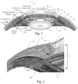
- Fig. 1 shows details of an anterior segment of an eye.
- An anterior segment of an eye 1 includes a cornea 2, anterior chamber 3, iris 4, lens 5, conjunctiva 6, Tenon's Capsule 7, sclera 8, ciliary muscle 9, choroid 10, and suprachoroidal space 11.
- the suprachoroidal space 11 is bounded between the choroid 10 and the sclera 8.
- the choroid 10 contains blood vessels that interpenetrate the upper part of the ciliary body 9. Those blood vessels become more organized into a more distinct layer more posterior to the anterior chamber 3.
- a clear corneal incision 13, or a precisely articulated incision used in the cornea 2, is used to access the anterior chamber 3 during ab interno anterior segment surgery such as cataract surgery. Clear corneal incision 13 can be made with a scalpel or with a laser.
- the anterior chamber 3 is typically filled with a visco-elastic material during cataract surgery and procedures of this nature.
- Dotted circle 12 denotes a portion of interest to this disclosure and is shown in greater detail in Fig. 2 .
- the suprachoroidal space 11 is situated just below a scleral spur 20.
- a surgeon looking through a gonio lens (not shown) into the anterior chamber 3 through the cornea 2 can readily identify the scleral spur 20 and the entrance to the suprachoroidal space 11.
- Fig. 3A shows an embodiment of a glaucoma drainage device 30, hereinafter referred to as a "wedge", that is configured for insertion into the suprachoroidal space 11, as shown in Fig. 5 , for example, and described in greater detail below.
- the wedge 30 is comprised of an elongated body 31, hereinafter referred to as a "rod”, which is shown as being a filleted rectangular (rectangular in terms of the overall planform) rod with a tapered distal end 32.
- the rod 31 has outer surfaces 42 (top surface) and 43 (bottom surface) that define at least one open groove or channel 33 extending from at or near a proximal end 50 towards the distal end 32.
- the groove or channel 33 extends parallel to the longitudinal axis A-A.
- the upper surface 42 and lower surface 43 are planar when the wedge 30 is laid on a flat surface and not subject to external forces.
- the open groove or channel 33 may also or alternatively be formed in either or both of the upper or lower surfaces 42 and 43.
- the taper angle of the distal end 32 is shallower than that shown in Fig. 3A so that the taper extends further and may extend all the way to a proximal end 50.
- proximal and distal refer to positions along axis A-A in Fig. 3A .
- the slot(s) 33 can be continuous throughout the entire length of the wedge 30 or it can stop anywhere along its length for example at an abutment 34 at or near the distal end 32 of the rod 31.
- Fig. 3B shows a cross-section of wedge 30 along section 3B-3B in Fig. 3A showing two slots 33a and 33b on each side of wedge 30.
- the cross-section has the appearance of an I-beam having two horizontal flanges, one on the top and a second on the bottom, spaced vertically by a vertical web.
- the wedge 30 is lumen-less and grooves or channels 33 formed on the outside surface(s) of the rod 31 are open. The grooves or channels 33 enable fluid to flow alongside the outer surface(s) of the wedge 30 and diffuse from the anterior chamber 3 into the suprachoroidal space 11, as will be described in greater detail below.
- the axial length of wedge 30 measured along axis A-A from the distal end 32 to the proximal end 50 can be from 3 mm to 10 mm, and preferably 6 mm.
- the cross-sectional dimensions depicted on Fig. 3B are width 37 of 0.5 mm to 1 mm, and preferably 0.75 mm.
- the height 36 is 0.4 to 0.8 mm, and preferably 0.5 mm.
- the width of slots 33, denoted as 38 can be from 0.05 mm to 0.25 mm, preferably 0.15 mm.
- An indentation or depth 39 of slots 33 into wedge 30 are less than 40% of the width 37 of wedge 30 and can range from 0.05 mm to 0.4 mm, and preferably 0.25 mm.
- Fig. 7 shows a cross section of a wedge 70 that has two lobes 70a and 70b that intersect thereby defining a set of open grooves or channels 73a and 73b on the outer surface of the wedge 70.
- Fig. 8 shows a cross-section of a wedge 80 that has three lobes 80a, 80b, and 80c, which intersect defining a set of three open grooves or channels 83a, 83b, and 83c on the outer surface of the wedge 80.
- the wedge 30 is made from any biomaterial including polyolefins such as poly(styrene-block-isobutylene-block-styrene) (SIBS), styrene ethylene butylene styrene (SEBS), polyhexene, polypropylene, polyethylene, and the like, as well as copolymers of the above.
- SIBS poly(styrene-block-isobutylene-block-styrene)
- SEBS styrene ethylene butylene styrene
- polyhexene polypropylene
- polyethylene polyethylene
- Other materials comprising the wedge 30 can include but are not limited to silicone rubber (polydimethylsiloxane and polyphenylsiloxane and copolymers thereof), polyurethane such as polyether urethane, polycarbonate urethane, polysilicone urethane, polyisobutylene urethane and other polyurethanes used for medical implantation; fluorinated polymers can also be used such as polyvinyldifluoride (PVDF) and fluorinated versions of the above.
- PVDF polyvinyldifluoride
- Other materials can be used for this embodiment include stiffer materials such as PEEK, polyimide, polysulfone, ridged polyurethane, polyamide, etc.
- Biological materials can also be used for the wedge such as crosslinked gelatin (porcine, equine, bovine, feline, etc.) crosslinked polysaccharides (gellen, pectin, hyaluronic acid, methyl cellulose, and the like).
- crosslinked gelatin porosin, bovine, feline, etc.
- polysaccharides gellen, pectin, hyaluronic acid, methyl cellulose, and the like.
- the preferred materials are those that are biocompatible and significantly flexible to take on the shape of the suprachoroidal space.
- a preferred material to be used in forming the wedge 30 is poly(styrene-block-isobutylene-block-styrene) (SIBS) of Shore 30A to 60A hardness as described in detail in U.S.
- the wedge 30 may be extruded as a long, contoured monofilament, which can be cut to length.
- the extruded, cut monofilament can then be heat-formed at one end (e.g., the distal end 32) to form features (e.g., abutment 34 and taper of the distal end 32) of the wedge 30 that may have not been formed by extrusion and cutting.
- Fig. 4 shows another embodiment of a wedge 30' which has a plurality of barbs 41 on an upper surface 42' and on a lower surface 43'.
- the barbs 41 are configured to engage the tissue defining the suprachoroidal space 11 so that when the wedge 30' in introduced into the suprachoroidal space 11, the barbs 41 will help retain and fixate the wedge 30' in its implanted position and inhibit migration or ejection of the wedge 30' back out of the suprachoroidal space 11. While the barbs 41 are shown as having flat outer surfaces 41a (parallel with the upper and lower surfaces 42' and 43') in Fig.
- the barbs can also have outer surfaces 41a that extend at non-zero angles relative to the upper and lower surfaces 42' and 43' to allow easy insertion into the suprachoroidal space 11, while resisting removal in the other direction.
- the barbs 41 are shown protruding from the surfaces of the wedge 30', the barbs 41 can also be indents, ridges, or grooves (not shown) formed in the surface.
- the wedge 30 is configured for implantation at least partly in the suprachoroidal space 11.
- the distal end 32 of the wedge 30 is located in the suprachoroidal space 11 and the proximal end 50 is located in the anterior chamber 3, as shown in Fig. 5 .
- the wedge 30 conforms to the curved shape of the suprachoroidal space 11, which is parallel to the curvature of the eye.
- the wedge 30 may extend 0.5 mm to 1 mm into the anterior chamber 3. This spacing can help prevent closure of the suprachoroidal space 11 around the proximal end 50 of the wedge 30, which, if closed, would cut off the flow of fluid from the anterior chamber 3 to the suprachoroidal space 11.
- Fig. 6 shows an end-view 60 (viewed from the proximal end 50 looking distally) of wedge 30 in the implanted configuration shown in Fig. 5 , as seen from the anterior chamber 3 using optical coherence tomography (OTC).
- OTC optical coherence tomography
- the wedge 30 can be implanted alone or in conjunction with one or more therapeutic agents. These therapeutic agents can be injected into the eye at the time of surgery or coated on the device or embedded within the device to elute therefrom. In addition, these therapeutic agents can be injected periodically following implantation of the wedge. Also, the wedge 30 may be formed from a biodegradable polymer matrix or coated with a biodegradable polymer matrix, where the biodegradable polymer matrix is loaded with a therapeutic agent that can be released from the matrix into the eye over time. The biodegradable polymer matrix can degrade over time in vivo (in the implanted position in the eye) and such degradation can be required to achieve the desired release rate of the therapeutic agent from the matrix into the eye over time.
- the biodegradable polymer matrix can be selected from the group consisting of one or more biodegradable polymers in varying combinations, such as polymers, copolymers, and block polymers.
- biodegradable polymers include polyglycolides, polylactides, polycaprolactones, polyglycerol sebacate, polycarbonates e.g.
- biopolyesters such as poly( ⁇ -hydroxyalcanoate)s (PHAs) and derived compounds, polyethylene oxide, polybutylene terepthalate, polydioxanones, hybrids, composites, collagen matrices with growth modulators, proteoglycans, glycosaminoglycans, vacuum formed SIS (small intestinal submucosa), fibers, chitin, and dextran. Any of these biodegradable polymers may be used alone or in combination with these or other biodegradable polymers in varying compositions.
- the biodegradable polymer matrix preferably includes biodegradable polymers such as polylactide (PLA), polyglycolic acid (PGA) polymer, poly (e-caprolactone) (PCL), polyacrylates, polymethacryates, or other copolymers.
- the pharmaceutical drug may be dispersed throughout the biodegradable polymeric matrix.
- the pharmaceutical drug may diffuse out from the biodegradable polymeric matrix to elute the drug and/or the pharmaceutical drug may separate from within the biodegradable polymer matrix and diffuse out from the biodegradable polymeric matrix to elute the drug. Examples of such a biodegradable polymer matrix are described in U.S. Patent 8,685,435 (Nivaggioli et al. ), the entire contents of which are incorporated herein by reference.
- the therapeutic agents(s) can include anti-proliferation agents that prevent or delay cell division, for example, by inhibiting replication of DNA, and/or by inhibiting spindle fiber formation, and/or by inhibiting cell migration) or other agents that minimize fibrosis. Examples of such therapeutic agents follow.
- therapeutic agents include the following: Visudyne, Lucentis (rhuFab V2 AMD), Combretastatin A4 Prodrug, SnET2, H8, VEGF Trap, Cand5, LS 11 (Taporfin Sodium), AdPEDF, RetinoStat, Integrin, Panzem, Retaane, Anecortave Acetate, VEGFR-1 mRNA, ARGENT cell-signalling technology, Angiotensin II Inhibitor, Accutane for Blindness, Macugen (PEGylated aptamer), PTAMD, Optrin, AK-1003, NX 1838, Antagonists of avb3 and 5, Neovastat, Eos 200-F and any other VEGF inhibitor.
- therapeutic agents can be used such as: mitomycin C, 5-fluorouracil, dexamethasone, corticosteroids (corticosteroid triamcinolone acetonide is most common), modified toxins, methotrexate, adriamycin, radionuclides (e.g., such as disclosed in U.S. Pat. No.
- protein kinase inhibitors including staurosporin, which is a protein kinase C inhibitor, as well as a diindolo alkaloids and stimulators of the production or activation of TGF-beta, including tamoxifen and derivatives of functional equivalents, e.g., plasmin, heparin, compounds capable of reducing the level or inactivating the lipoprotein Lp(a) or the glycoprotein apolipoprotein(a) thereof), nitric oxide releasing compounds (e.g., nitroglycerin) or analogs or functional equivalents thereof, paclitaxel or analogs or functional equivalents thereof (e.g., taxotere or an agent based on Taxol ® , whose active ingredient is paclitaxel), inhibitors of specific enzymes (such as the nuclear enzyme DNA topoisomerase II and DAN polymerase, RNA polyermase, aden
- therapeutic agents include the following: peptidic or mimetic inhibitors, such as antagonists, agonists, or competitive or non-competitive inhibitors of cellular factors that may trigger proliferation of cells or pericytes (e.g., cytokines (for example, interleukins such as IL-1), growth factors (for example, PDGF, TGF-alpha or -beta, tumor necrosis factor, smooth muscle-and endothelioal-derived growth factors such as endothelin or FGF), homing receptors (for example, for platelets or leukocytes), and extracellular matrix receptors (for example, integrins).
- cytokines for example, interleukins such as IL-1
- growth factors for example, PDGF, TGF-alpha or -beta, tumor necrosis factor, smooth muscle-and endothelioal-derived growth factors such as endothelin or FGF
- homing receptors for example, for platelets or leukocytes
- therapeutic agents include the following: subfragments of heparin, triazolopyrimidine (for example, trapidil, which is a PDGF antagonist), lovastatin, and prostaglandins E1 or I2.
- Figs. 9 to 13 show an inserter 90 that can be used to insert the wedge 30 into the suprachoroidal space 11 on one side of the eye using an ab interno approach via the clear corneal incision 13 ( Fig. 1 ) on a diametrically opposite side of the eye.
- the inserter 90 includes a handle 100 ( Fig. 12 ) that is made from a rigid material which may include medical grade polymers or metals such as polycarbonate, polypropylene, polysulfone, polyimide, polyamide, polyurethane, ABS, polymethylmethacrylate, and the like.
- Metals can include iron, stainless steel, nickel, titanium, gold, platinum and alloys of the above.
- the inserter includes an elongated guide rod 91 that is coupled to the handle 100 and extends from a proximal end 96 at the distal end of the handle 100 to a distal end 97 spaced axially along axis A-A from the proximal end 96. Slots 93 are formed on opposite sides of the guide rod 91 and the slots may extend into the handle 100.
- the inserter includes rods 92 which are coupled to the handle 100 and area configured to translate in the slots 93.
- the rods 92 and the guide rod 91 may be formed from metal (e.g., aluminum, stainless steel, titanium) and may be planar or prebent or curved to facilitate positioning of the wedge 30 in the eye, as will be described in greater detail below.
- Each rod 92 has a thickness and width sufficient that they fit in and slide relative to open groove or channel 33. Also, the rods may have a width that is about the width 39 of the open groove or channel 33.
- a thumb slide 94 is rigidly attached to the rods 92 within the handle 100 and the thumb slide 94 is configured to translate with the rods 92.
- the handle defines a slot 95 in which the thumb slide 94 translates.
- the handle 100, slots 95 and 93, and rods 92 extend parallel to axis A-A. Translational movement of the thumb slide 94 in the slot 95 causes corresponding movement of the rods 92 in their slots 93.
- the rods 92 can be positioned between an extended position shown in Figs. 9 and 11 , in which the thumb slide 94 is moved toward a distal end of the slot 95, and a retracted configuration as shown in Fig. 10 , in which the thumb slide 94 is moved towards an opposite, proximal end of the slot 95.
- the movement of the thumb slide 94 and the rods 92 may be used to implant the wedge 30 in the suprachoroidal space 11 as described in greater detail below.
- the inserter 90 functions as follows.
- the inserter 90 and the wedge 30 are coupled together, as shown, for example, in Fig. 11 .
- the slots 93 of the extension rod 93 are configured to align with open grooves or slots 33 of the wedge 30 so that rods 92 may span slots 33 and 93 in the extended configuration to couple the wedge 30 to the inserter 90, as shown in Figs. 11 and 12 .
- rods 92 of inserter 90 are received in slots 33a and 33b of wedge 30 such that distal ends 92a ( Fig. 9 ) of the rods 92 engage the abutment 34 of wedge 30.
- the proximal end 50 of the wedge 30 engages or otherwise abuts the distal end 97 of the extension rod 91.
- the wedge 30 may be pre-assembled with the inserter 90 and provided to a user as a kit.
- the user holds the inserter 90 while introducing the distal end 32 of the wedge 30 first into the clear corneal incision 13 with the use of a gonioscope (not shown) as well as a viscous fluid (not shown) in the anterior chamber 3 to maintain it open.
- the distal end 97 of the extension rod 91 follows the wedge 30 and is introduced into the eye.
- the axial length of the extension rod 91 is sufficient that the handle 100 remains outside of the eye at all times during use of the inserter 90.
- the width and height of the extension rod 91 are preferably equal to or less than the width 37 and height 36 of the wedge 30 so that the extension rod 91 does not enlarge the pathway through the eye caused by the positioning of the wedge 30 during its implantation.
- the distal end 32 of the wedge 30 is pushed by at least one of the extension rod 91 and the rods 92 and advanced diametrically across the anterior chamber 3 from the corneal incision 13 towards the scleral spur 20.
- the distal end 32 of the wedge 30 is advanced through the trabecular meshwork 14, and between the interface of the scleral spur 20 and the ciliary body, and finally into the suprachoroidal space 11 (just to the left of it in Fig. 5 ).
- the wedge 30 By pushing the ends 92a of the rods 92 against abutment 34 and/or by pushing the distal end 97 of the extension rod 91 against the proximal end 50 of the wedge 30, the wedge 30 can be pushed into suprachoroidal space 11.
- the thumb slide 94 can be retracted proximally in slot 95, which also retracts the rods 92 proximally from the grooves 33a and 33b.
- the extension rod 91 of the inserter 90 can be retracted from the eye, leaving the wedge 30 implanted in the eye in the implanted configuration shown in Fig. 5 .
- the inserter 90 includes a spring or other actuation mechanism to automatically retract the thumb slide 94 from the extended position when the thumb slide 94 is pressed (i.e., pressed downwardly in Fig. 11 ).
- the inserter 90 may include a lock mechanism configured lock the position of the thumb slide 94 in the extended configuration shown in Fig. 11 to prevent inadvertent deployment or decoupling of the wedge 90.
- the inserter handle 100 can be grasped and held in a user's hand so that the user's thumb can actuate the thumb slide 94.
- Portions of the rods 92 can have dimensions that are larger than the dimensions of the slots 33 (i.e., they can have a radially outer portion that is outside the grooves 33).
- the rods may have a "T" shaped cross-section and have an outer beam portion that extends along a plane perpendicular to the portion of the rods received in the slots 33.
- the outer beam portion may have dimensions larger than those of the slots 33 to provide the rods 92 more columnar strength (slots 33 will flex larger).
- Fig. 13 shows another alternate embodiment of the inserter 90 and the wedge 30 in which a wedge 30" is formed like wedge 30 but does not have abutments 34 and in which ends 92a" are formed with sharp cutting surfaces that extend distally of the distal end 32" of the wedge 30".
- the sharp cutting surfaces of ends 92a" can facilitate cutting tissue ahead of the inclined surfaces at the distal end 32" of the wedge 30".
- a glaucoma drainage device comprising: an elongated body extending axially from a distal end to a proximal end, the distal end formed as a wedge with a leading distal edge, the body having one or more outer surfaces that define at least one open groove extending from at or near the proximal end towards the distal end of the body, wherein the elongated body is configured to lodge in the suprachoroidal space of an eye and extend into the anterior chamber of the eye to permit aqueous humor from the anterior chamber of the eye to flow along the open grove from the anterior chamber of the eye to the suprachoroidal space of the eye.
- the body defines an abutment at or near a distal end of the at least one open groove, or the body has an upper outer surface and a lower outer surface that are planar.
- the body is formed of at least one of poly(styrene-block-isobutylene-block-styrene) (SIBS), styrene ethylene butylene styrene (SEBS), polyhexene, polypropylene, and polyethylene.
- SIBS poly(styrene-block-isobutylene-block-styrene)
- SEBS styrene ethylene butylene styrene
- polyhexene polypropylene
- polyethylene polyethylene
- a glaucoma device kit comprising: a glaucoma drainage device including an elongated body extending axially from a distal end to a proximal end, the distal end formed as a wedge with a leading distal edge, the body having one or more outer surfaces that define at least one open groove extending from at or near the proximal end towards the distal end of the body, wherein the elongated body is configured to lodge in the suprachoroidal space of an eye and extend into the anterior chamber of the eye to permit aqueous humor from the anterior chamber of the eye to flow along the open grove from the anterior chamber of the eye to the suprachoroidal space of the eye; and an inserter coupled to the glaucoma drainage device, the inserter configured to deliver and position the glaucoma drainage device in the suprachoroidal space and to decouple from the glaucoma drainage device to deploy the glaucoma drainage device in the suprachoroidal space.
- the inserter includes a handle and at least one rod configured for longitudinal translation relative to the handle, the at least one rod being configured for longitudinal translation in the at least one open groove of the body of the glaucoma drainage device, wherein when the inserter is coupled to the glaucoma drainage device, the rods are in an extended configuration in which the rod is at least located in a portion of the open groove of the body of the glaucoma drainage device.
- Clause 7 The kit according to clause 6, wherein: the inserter is configured to decouple from the glaucoma drainage device by reconfiguring the at least one rod from the extended configuration to a retracted configuration in which the rod is not located in a portion of the open groove of the glaucoma drainage device.
- the at least one rod is coupled to a slide member configured for actuation by a user's hand, the inserter handle defining a longitudinal slot extending axially along the length of the handle and parallel with the at least one rod, wherein the slide member is configured to slide within the slot to move the rod between the extended and retracted configurations.
- a method of implanting a glaucoma drainage device comprising: providing a glaucoma drainage device including an elongated body extending axially from a distal end to a proximal end, the distal end formed as a wedge with a leading distal edge, the body having one or more outer surfaces that define at least one open groove extending from at or near the proximal end towards the distal end of the body, wherein the elongated body is configured to lodge in the suprachoroidal space of an eye and extend into the anterior chamber of the eye to permit aqueous humor from the anterior chamber of the eye to flow along the open grove from the anterior chamber of the eye to the suprachoroidal space of the eye; providing an inserter coupled to the glaucoma drainage device, the inserter having a handle configured to be grasped by a user, the inserter configured to deliver and position the glaucoma drainage device in the suprachoroidal space and to decouple from the glaucoma drainage device to deploy the implant in
- positioning the glaucoma drainage device at a desired implanted position in the suprachoroidal space includes positioning the distal end of the glaucoma drainage device in the suprachoroidal space and positioning the proximal end of the glaucoma drainage device in the anterior chamber.
- Clause 11 The method according to clause 10, wherein: at the desired position, the glaucoma drainage device extends about 0.5 mm to 1 mm into the anterior chamber.
- the inserter includes at least one rod configured for longitudinal translation relative to the handle, the at least one rod being configured for longitudinal translation in the at least one open groove of the body of the glaucoma drainage device, wherein when the inserter is coupled to the glaucoma drainage device, the rods are in an extended configuration in which the rod is at least located in a portion of the open groove of the body of the glaucoma drainage device.
- Clause 14 The method according to clause 13, wherein: the inserter is configured to decouple from the glaucoma drainage device by reconfiguring the at least one rod from the extended configuration to a retracted configuration in which the rod is not located in a portion of the open groove of the body of the glaucoma drainage device, and wherein decoupling the inserter from the glaucoma drainage device includes reconfiguring the at least one rod form the extended configuration to the retracted configuration.
- Clause 15 The method according to clause 14, wherein: the at least one rod is coupled to a slide member configured for actuation by the user's hand, the inserter handle defining a longitudinal slot extending axially along the length of the handle and parallel with the at least one rod, wherein the slide member is configured to slide within the slot to move the rod between the extended and retracted configurations.
Abstract
Description
- This application claims priority to
U.S. Provisional Patent Application No. 62/518,944 filed June 13, 2017 - The present disclosure relates to the treatment of glaucoma, and more particularly, to medical devices and methods for creating a drainage pathway to divert aqueous humor out of the anterior chamber of the eye such that pressure within the eye is reduced.
- Aqueous humor is produced by the eye's ciliary body and flows from the ciliary body into the anterior chamber, out through a spongy tissue at the front of the eye called the trabecular meshwork and into a drainage canal. In a healthy eye, continuous drainage of aqueous humor keeps intraocular pressure at a normal level. However, in most types of glaucoma, proper circulation of aqueous humor is disrupted, causing the level of intraocular pressure to be elevated. In open-angle glaucoma, fluid does not flow freely through the trabecular meshwork, causing an increase in intraocular pressure, damage to the optic nerve and vision loss. Reduction of intraocular pressure is a means of stopping the progression of optic nerve damage, which if untreated can lead to blindness.
- The suprachoroidal space is a space in the eye that lies between the sclera and the choroid. It is known that aqueous humor in the suprachoroidal space can drain therefrom and cause a reduction in intraocular pressure. Although it is not well understood where aqueous humor drains to once it reaches the suprachoroidal space, there are references to aqueous humor draining into the choroid vessels as well as into the venous plexus of the sclera and to the episcleral veins.
- Alcon Laboratories, Inc. of Fort Worth, Texas has developed the CyPass® Microstent that includes a tubular body with an internal lumen that drains aqueous humor from the anterior chamber of the eye into the suprachoroidal space of the eye to lower intraocular pressure in the eye.
- Widening the space between the choroid and the sclera (suprachoroidal space or supraciliary space) enables aqueous humor to enter the suprachoroidal space and drain therefrom through an alternate drainage pathway of the eye and reduce intraocular pressure. The terms "suprachoroidal space" and "supraciliary space" refer to the same space in the eye and those two terms, therefore, are interchangeable. According to one aspect of the disclosure, a device is provided for implantation into the suprachoroidal space of the eye to promote drainage of aqueous humor from the anterior chamber of the eye to the suprachoroidal space of the eye in order to reduce intraocular pressure. The device may be made from a flexible, bio-inert, and biocompatible material that can be inserted into the suprachoroidal space of the eye using an ab interno approach, conform to the curvature of the tissue surrounding the suprachoroidal space (i.e., the sclera and the choroid), and remain in place for a long period of time.
- According to one aspect, further details of which are described herein, the device includes an elongated body extending axially from a distal end to a proximal end. The distal end of elongate body forms a wedge with a leading distal edge. During implantation of the device into the suprachoroidal space of the eye, the wedge with leading distal edge can facilitate penetration into and spreading open the tissue of the suprachoroidal space of the eye. The elongate body has one or more outer surfaces that define at least one open groove extending from at or near the proximal end towards the distal end of the body. With the distal end of the elongate body located in the suprachoroidal space of the eye and the distal end of the elongate body extending into the anterior chamber of the eye, the at least one open groove is configured such that aqueous humor flows along the open groove from the anterior chamber of the eye to the suprachoroidal space of the eye. Due to the open nature of the open groove, the flow path of the aqueous humor that flows along the open groove can be bounded by ocular tissue disposed adjacent the open groove along the length of the open groove.
- In embodiment(s), the body of the device defines an abutment at a distal end of the at least one open groove. Also, in embodiment(s), the body has an upper outer surface and a lower outer surface that are substantially planar in form. In one embodiment, barbs extend from the upper and lower surfaces. The barbs may be tapered to permit insertion in one direction and resist removal in an opposite direction.
- In embodiment(s), the device is formed from a soft flexible polymeric material. Examples of such soft flexible polymeric material includes poly(styrene-block-isobutylene-block-styrene) (SIBS), styrene ethylene butylene styrene (SEBS), polyhexene, polypropylene, polyethylene, and combinations thereof. The material may have a hardness of Shore 30A to 60A.
- According to another aspect, further details of which are described herein, a system includes the device and an inserter coupled to the device. The inserter is configured to hold the device while positioning the distal end of the device in the suprachoroidal space and to decouple from the device to deploy the device in a desired location in the suprachoroidal space. The inserter may include a handle and at least one rigid member configured for longitudinal translation relative to the handle. Each rigid member is configured for longitudinal translation in a corresponding open groove of the device. The inserter holds the device with each rigid member in an extended configuration in which the rigid member extends along at least a portion of the corresponding open groove of the device. In embodiment(s), the inserter is configured to decouple from the device by reconfiguring each rigid member from the extended configuration to a retracted configuration in which the rigid member is removed from the open groove of the device.
- As used herein, "rigid" means that the inserter will not bend or buckle under a range of forces (e.g., axial and radial compressive forces) that may be imparted to the inserter by the hand of the user when the inserter is introduced into the eye, as described in greater detail below. Also, as used herein, "flexible" means that the device, if unsupported by the inserter, will bend or buckle under the axial and radial compressive forces that may be imparted to the inserter during its use.
- In embodiment(s), the at least one rod is coupled to a slide member configured for actuation by a user's hand. The inserter handle defines a longitudinal slot extending axially along the length of the handle and parallel with the at least one rod, and the slide member is configured to slide within the slot to move the rod between the extended and retracted configurations.
- According to yet another aspect, further details of which are described herein, a method of implanting the device includes providing the device coupled to the inserter, introducing the device into the eye while maintaining the handle outside of the eye, positioning the device at a desired implanted position in the suprachoroidal space, and, with the device positioned at the desired implanted position, decoupling the inserter from the device. In embodiment(s) positioning the device at a desired implanted position in the suprachoroidal space includes positioning the distal end of the device in the suprachoroidal space and positioning the proximal end of the device in the anterior chamber. At the desired position, the device may extend about 0.5 mm to 1 mm into the anterior chamber.
-
-
Fig. 1 is a section view of an anterior segment of an eye. -
Fig. 2 is an exploded view of the portion ofFig. 1 surrounded by the dotted circle. -
Fig. 3A is an isometric view of an embodiment of a glaucoma drainage device in accordance with this disclosure. -
Fig. 3B is a section view of the glaucoma drainage device ofFig. 3A viewed alongsection 3B-3B inFig. 3A . -
Fig. 4 is an isometric view of another embodiment of a glaucoma drainage device in accordance with this disclosure. -
Figs. 5 and 6 show the glaucoma drainage device ofFigs. 3A and 3B in an implanted configuration. -
Figs. 7 and 8 show alternative cross sections, respectively, of two other embodiments of glaucoma drainage device in accordance with this disclosure. -
Fig. 9 shows a portion of an embodiment of a deployment tool in an extended configuration. -
Fig. 10 shows the portion of the deployment tool ofFig. 9 in a retracted configuration. -
Fig. 11 shows the portion of the deployment tool ofFig. 9 in the extended configuration coupled to the glaucoma drainage device ofFigs. 3A and 3B . -
Fig. 12 shows the deployment tool ofFigs. 9 to 11 with its handle coupled to the glaucoma drainage device ofFigs. 3A and 3B . -
Fig. 13 shows an alternative embodiment of the deployment tool ofFigs. 9 to 12 and alternative embodiment of the glaucoma drainage device ofFigs. 3A and 3B . -
Fig. 1 shows details of an anterior segment of an eye. An anterior segment of an eye 1 includes acornea 2,anterior chamber 3, iris 4, lens 5, conjunctiva 6, Tenon's Capsule 7,sclera 8,ciliary muscle 9,choroid 10, andsuprachoroidal space 11. Thesuprachoroidal space 11 is bounded between the choroid 10 and thesclera 8. The choroid 10 contains blood vessels that interpenetrate the upper part of theciliary body 9. Those blood vessels become more organized into a more distinct layer more posterior to theanterior chamber 3. A clearcorneal incision 13, or a precisely articulated incision used in thecornea 2, is used to access theanterior chamber 3 during ab interno anterior segment surgery such as cataract surgery. Clearcorneal incision 13 can be made with a scalpel or with a laser. Theanterior chamber 3 is typically filled with a visco-elastic material during cataract surgery and procedures of this nature. - Dotted
circle 12 denotes a portion of interest to this disclosure and is shown in greater detail inFig. 2 . Thesuprachoroidal space 11 is situated just below ascleral spur 20. A surgeon looking through a gonio lens (not shown) into theanterior chamber 3 through thecornea 2 can readily identify thescleral spur 20 and the entrance to thesuprachoroidal space 11. -
Fig. 3A shows an embodiment of aglaucoma drainage device 30, hereinafter referred to as a "wedge", that is configured for insertion into thesuprachoroidal space 11, as shown inFig. 5 , for example, and described in greater detail below. In the embodiment shown, thewedge 30 is comprised of anelongated body 31, hereinafter referred to as a "rod", which is shown as being a filleted rectangular (rectangular in terms of the overall planform) rod with a tapereddistal end 32. Therod 31 has outer surfaces 42 (top surface) and 43 (bottom surface) that define at least one open groove orchannel 33 extending from at or near aproximal end 50 towards thedistal end 32. The groove orchannel 33 extends parallel to the longitudinal axis A-A. Theupper surface 42 andlower surface 43, are planar when thewedge 30 is laid on a flat surface and not subject to external forces. Of course, the open groove orchannel 33 may also or alternatively be formed in either or both of the upper orlower surfaces - In one alternative embodiment, not shown, the taper angle of the
distal end 32 is shallower than that shown inFig. 3A so that the taper extends further and may extend all the way to aproximal end 50. The terms "proximal" and "distal" refer to positions along axis A-A inFig. 3A . The slot(s) 33 can be continuous throughout the entire length of thewedge 30 or it can stop anywhere along its length for example at anabutment 34 at or near thedistal end 32 of therod 31. -
Fig. 3B shows a cross-section ofwedge 30 alongsection 3B-3B inFig. 3A showing twoslots wedge 30. The cross-section has the appearance of an I-beam having two horizontal flanges, one on the top and a second on the bottom, spaced vertically by a vertical web. Thewedge 30 is lumen-less and grooves orchannels 33 formed on the outside surface(s) of therod 31 are open. The grooves orchannels 33 enable fluid to flow alongside the outer surface(s) of thewedge 30 and diffuse from theanterior chamber 3 into thesuprachoroidal space 11, as will be described in greater detail below. - The axial length of
wedge 30 measured along axis A-A from thedistal end 32 to theproximal end 50 can be from 3 mm to 10 mm, and preferably 6 mm. The cross-sectional dimensions depicted onFig. 3B arewidth 37 of 0.5 mm to 1 mm, and preferably 0.75 mm. Theheight 36 is 0.4 to 0.8 mm, and preferably 0.5 mm. The width ofslots 33, denoted as 38, can be from 0.05 mm to 0.25 mm, preferably 0.15 mm. An indentation ordepth 39 ofslots 33 intowedge 30 are less than 40% of thewidth 37 ofwedge 30 and can range from 0.05 mm to 0.4 mm, and preferably 0.25 mm. Although the drawings shown the leading edge of thewedge 30 at thedistal end 32 as a sharp edge, the edge may have a radius of about 0.005 inch. - Although the
wedge 30 is shown as an I-beam-shaped cross-section inFig. 3B , other cross-sectional shapes can be used as exemplified inFigs. 7 and 8 . For example,Fig. 7 shows a cross section of awedge 70 that has two lobes 70a and 70b that intersect thereby defining a set of open grooves orchannels wedge 70. Also,Fig. 8 shows a cross-section of awedge 80 that has three lobes 80a, 80b, and 80c, which intersect defining a set of three open grooves orchannels wedge 80. - The
wedge 30 is made from any biomaterial including polyolefins such as poly(styrene-block-isobutylene-block-styrene) (SIBS), styrene ethylene butylene styrene (SEBS), polyhexene, polypropylene, polyethylene, and the like, as well as copolymers of the above. Other materials comprising thewedge 30 can include but are not limited to silicone rubber (polydimethylsiloxane and polyphenylsiloxane and copolymers thereof), polyurethane such as polyether urethane, polycarbonate urethane, polysilicone urethane, polyisobutylene urethane and other polyurethanes used for medical implantation; fluorinated polymers can also be used such as polyvinyldifluoride (PVDF) and fluorinated versions of the above. Other materials can be used for this embodiment include stiffer materials such as PEEK, polyimide, polysulfone, ridged polyurethane, polyamide, etc. Biological materials can also be used for the wedge such as crosslinked gelatin (porcine, equine, bovine, feline, etc.) crosslinked polysaccharides (gellen, pectin, hyaluronic acid, methyl cellulose, and the like). However, the preferred materials are those that are biocompatible and significantly flexible to take on the shape of the suprachoroidal space. A preferred material to be used in forming thewedge 30 is poly(styrene-block-isobutylene-block-styrene) (SIBS) of Shore 30A to 60A hardness as described in detail inU.S. Patents 9,101,444 9,044,301 7,837,644 ;7,594,899 ; and7,431,709 , herein incorporated by reference in their entireties. Thewedge 30 may be extruded as a long, contoured monofilament, which can be cut to length. The extruded, cut monofilament can then be heat-formed at one end (e.g., the distal end 32) to form features (e.g.,abutment 34 and taper of the distal end 32) of thewedge 30 that may have not been formed by extrusion and cutting. -
Fig. 4 shows another embodiment of a wedge 30' which has a plurality ofbarbs 41 on an upper surface 42' and on a lower surface 43'. Thebarbs 41 are configured to engage the tissue defining thesuprachoroidal space 11 so that when the wedge 30' in introduced into thesuprachoroidal space 11, thebarbs 41 will help retain and fixate the wedge 30' in its implanted position and inhibit migration or ejection of the wedge 30' back out of thesuprachoroidal space 11. While thebarbs 41 are shown as having flatouter surfaces 41a (parallel with the upper and lower surfaces 42' and 43') inFig. 4 , the barbs can also haveouter surfaces 41a that extend at non-zero angles relative to the upper and lower surfaces 42' and 43' to allow easy insertion into thesuprachoroidal space 11, while resisting removal in the other direction. Although thebarbs 41 are shown protruding from the surfaces of the wedge 30', thebarbs 41 can also be indents, ridges, or grooves (not shown) formed in the surface. - As noted above, the
wedge 30 is configured for implantation at least partly in thesuprachoroidal space 11. Preferably, when in a fully implanted configuration, thedistal end 32 of thewedge 30 is located in thesuprachoroidal space 11 and theproximal end 50 is located in theanterior chamber 3, as shown inFig. 5 . Note that as shown inFig. 5 , thewedge 30 conforms to the curved shape of thesuprachoroidal space 11, which is parallel to the curvature of the eye. In the fully implanted configuration, thewedge 30 may extend 0.5 mm to 1 mm into theanterior chamber 3. This spacing can help prevent closure of thesuprachoroidal space 11 around theproximal end 50 of thewedge 30, which, if closed, would cut off the flow of fluid from theanterior chamber 3 to thesuprachoroidal space 11. -
Fig. 6 shows an end-view 60 (viewed from theproximal end 50 looking distally) ofwedge 30 in the implanted configuration shown inFig. 5 , as seen from theanterior chamber 3 using optical coherence tomography (OTC). Insertion ofwedge 30 into thesuprachoroidal space 11 causes cleavage or spreading between portions of one or more of thesclera 8,choroid 10,trabecular meshwork 14, andscleral spur 20, forming a cleft 61 between the tissues and thewedge 30, which increases the size of the fluid opening between theanterior chamber 3 and thesuprachoroidal space 11 to promote the flow of aqueous humor from theanterior chamber 3 into to thesuprachoroidal space 11. - The
wedge 30 can be implanted alone or in conjunction with one or more therapeutic agents. These therapeutic agents can be injected into the eye at the time of surgery or coated on the device or embedded within the device to elute therefrom. In addition, these therapeutic agents can be injected periodically following implantation of the wedge. Also, thewedge 30 may be formed from a biodegradable polymer matrix or coated with a biodegradable polymer matrix, where the biodegradable polymer matrix is loaded with a therapeutic agent that can be released from the matrix into the eye over time. The biodegradable polymer matrix can degrade over time in vivo (in the implanted position in the eye) and such degradation can be required to achieve the desired release rate of the therapeutic agent from the matrix into the eye over time. - In embodiments, the biodegradable polymer matrix can be selected from the group consisting of one or more biodegradable polymers in varying combinations, such as polymers, copolymers, and block polymers. Some examples of such biodegradable polymers include polyglycolides, polylactides, polycaprolactones, polyglycerol sebacate, polycarbonates e.g. tyrosine derived, biopolyesters such as poly(β-hydroxyalcanoate)s (PHAs) and derived compounds, polyethylene oxide, polybutylene terepthalate, polydioxanones, hybrids, composites, collagen matrices with growth modulators, proteoglycans, glycosaminoglycans, vacuum formed SIS (small intestinal submucosa), fibers, chitin, and dextran. Any of these biodegradable polymers may be used alone or in combination with these or other biodegradable polymers in varying compositions. The biodegradable polymer matrix preferably includes biodegradable polymers such as polylactide (PLA), polyglycolic acid (PGA) polymer, poly (e-caprolactone) (PCL), polyacrylates, polymethacryates, or other copolymers. The pharmaceutical drug may be dispersed throughout the biodegradable polymeric matrix. The pharmaceutical drug may diffuse out from the biodegradable polymeric matrix to elute the drug and/or the pharmaceutical drug may separate from within the biodegradable polymer matrix and diffuse out from the biodegradable polymeric matrix to elute the drug. Examples of such a biodegradable polymer matrix are described in
U.S. Patent 8,685,435 (Nivaggioli et al. ), the entire contents of which are incorporated herein by reference. - The therapeutic agents(s) can include anti-proliferation agents that prevent or delay cell division, for example, by inhibiting replication of DNA, and/or by inhibiting spindle fiber formation, and/or by inhibiting cell migration) or other agents that minimize fibrosis. Examples of such therapeutic agents follow.
- Representative examples of therapeutic agents include the following: Visudyne, Lucentis (rhuFab V2 AMD), Combretastatin A4 Prodrug, SnET2, H8, VEGF Trap, Cand5, LS 11 (Taporfin Sodium), AdPEDF, RetinoStat, Integrin, Panzem, Retaane, Anecortave Acetate, VEGFR-1 mRNA, ARGENT cell-signalling technology, Angiotensin II Inhibitor, Accutane for Blindness, Macugen (PEGylated aptamer), PTAMD, Optrin, AK-1003, NX 1838, Antagonists of avb3 and 5, Neovastat, Eos 200-F and any other VEGF inhibitor.
- Other therapeutic agents can be used such as: mitomycin C, 5-fluorouracil, dexamethasone, corticosteroids (corticosteroid triamcinolone acetonide is most common), modified toxins, methotrexate, adriamycin, radionuclides (e.g., such as disclosed in
U.S. Pat. No. 4,897,255 , herein incorporated by reference in its entirety), protein kinase inhibitors (including staurosporin, which is a protein kinase C inhibitor, as well as a diindolo alkaloids and stimulators of the production or activation of TGF-beta, including tamoxifen and derivatives of functional equivalents, e.g., plasmin, heparin, compounds capable of reducing the level or inactivating the lipoprotein Lp(a) or the glycoprotein apolipoprotein(a) thereof), nitric oxide releasing compounds (e.g., nitroglycerin) or analogs or functional equivalents thereof, paclitaxel or analogs or functional equivalents thereof (e.g., taxotere or an agent based on Taxol®, whose active ingredient is paclitaxel), inhibitors of specific enzymes (such as the nuclear enzyme DNA topoisomerase II and DAN polymerase, RNA polyermase, adenl guanyl cyclase), superoxide dismutase inhibitors, terminal deoxynucleotidyl-transferas, reverse transcriptase, antisense oligonucleotides that suppress cell proliferation, angiogenesis inhibitors (e.g., endostatin, angiostatin and squalamine), rapamycin or sirolimus and its derivatives such as everolimus or zoltarolimus, cerivastatin, and flavopiridol and suramin and the like. - Other examples of therapeutic agents include the following: peptidic or mimetic inhibitors, such as antagonists, agonists, or competitive or non-competitive inhibitors of cellular factors that may trigger proliferation of cells or pericytes (e.g., cytokines (for example, interleukins such as IL-1), growth factors (for example, PDGF, TGF-alpha or -beta, tumor necrosis factor, smooth muscle-and endothelioal-derived growth factors such as endothelin or FGF), homing receptors (for example, for platelets or leukocytes), and extracellular matrix receptors (for example, integrins).
- Still other examples of therapeutic agents include the following: subfragments of heparin, triazolopyrimidine (for example, trapidil, which is a PDGF antagonist), lovastatin, and prostaglandins E1 or I2.
-
Figs. 9 to 13 show aninserter 90 that can be used to insert thewedge 30 into thesuprachoroidal space 11 on one side of the eye using an ab interno approach via the clear corneal incision 13 (Fig. 1 ) on a diametrically opposite side of the eye. Theinserter 90 includes a handle 100 (Fig. 12 ) that is made from a rigid material which may include medical grade polymers or metals such as polycarbonate, polypropylene, polysulfone, polyimide, polyamide, polyurethane, ABS, polymethylmethacrylate, and the like. Metals can include iron, stainless steel, nickel, titanium, gold, platinum and alloys of the above. - The inserter includes an
elongated guide rod 91 that is coupled to thehandle 100 and extends from aproximal end 96 at the distal end of thehandle 100 to a distal end 97 spaced axially along axis A-A from theproximal end 96.Slots 93 are formed on opposite sides of theguide rod 91 and the slots may extend into thehandle 100. The inserter includesrods 92 which are coupled to thehandle 100 and area configured to translate in theslots 93. Therods 92 and theguide rod 91 may be formed from metal (e.g., aluminum, stainless steel, titanium) and may be planar or prebent or curved to facilitate positioning of thewedge 30 in the eye, as will be described in greater detail below. Eachrod 92 has a thickness and width sufficient that they fit in and slide relative to open groove orchannel 33. Also, the rods may have a width that is about thewidth 39 of the open groove orchannel 33. - A
thumb slide 94 is rigidly attached to therods 92 within thehandle 100 and thethumb slide 94 is configured to translate with therods 92. Specifically, the handle defines aslot 95 in which thethumb slide 94 translates. Thehandle 100,slots rods 92 extend parallel to axis A-A. Translational movement of thethumb slide 94 in theslot 95 causes corresponding movement of therods 92 in theirslots 93. Therods 92 can be positioned between an extended position shown inFigs. 9 and 11 , in which thethumb slide 94 is moved toward a distal end of theslot 95, and a retracted configuration as shown inFig. 10 , in which thethumb slide 94 is moved towards an opposite, proximal end of theslot 95. The movement of thethumb slide 94 and therods 92 may be used to implant thewedge 30 in thesuprachoroidal space 11 as described in greater detail below. - In one embodiment, the
inserter 90 functions as follows. Theinserter 90 and thewedge 30 are coupled together, as shown, for example, inFig. 11 . Theslots 93 of theextension rod 93 are configured to align with open grooves orslots 33 of thewedge 30 so thatrods 92 may spanslots wedge 30 to theinserter 90, as shown inFigs. 11 and12 . Looking atFig. 11 ,rods 92 ofinserter 90 are received inslots wedge 30 such thatdistal ends 92a (Fig. 9 ) of therods 92 engage theabutment 34 ofwedge 30. When thewedge 30 is coupled to theinserter 90, theproximal end 50 of thewedge 30 engages or otherwise abuts the distal end 97 of theextension rod 91. Thewedge 30 may be pre-assembled with theinserter 90 and provided to a user as a kit. - With the
wedge 30 coupled to theinserter 90 as shown inFig. 11 , the user holds theinserter 90 while introducing thedistal end 32 of thewedge 30 first into the clearcorneal incision 13 with the use of a gonioscope (not shown) as well as a viscous fluid (not shown) in theanterior chamber 3 to maintain it open. After thewedge 30 is introduced into the eye, the distal end 97 of theextension rod 91 follows thewedge 30 and is introduced into the eye. The axial length of theextension rod 91 is sufficient that thehandle 100 remains outside of the eye at all times during use of theinserter 90. The width and height of theextension rod 91 are preferably equal to or less than thewidth 37 andheight 36 of thewedge 30 so that theextension rod 91 does not enlarge the pathway through the eye caused by the positioning of thewedge 30 during its implantation. - The
distal end 32 of thewedge 30 is pushed by at least one of theextension rod 91 and therods 92 and advanced diametrically across theanterior chamber 3 from thecorneal incision 13 towards thescleral spur 20. Thedistal end 32 of thewedge 30 is advanced through thetrabecular meshwork 14, and between the interface of thescleral spur 20 and the ciliary body, and finally into the suprachoroidal space 11 (just to the left of it inFig. 5 ). When crossing theanterior chamber 3, it may be useful to maintain the plane of the upper andlower surfaces wedge 30 parallel to the plane of the iris. By pushing theends 92a of therods 92 againstabutment 34 and/or by pushing the distal end 97 of theextension rod 91 against theproximal end 50 of thewedge 30, thewedge 30 can be pushed intosuprachoroidal space 11. Once thewedge 30 is in the fully implanted configuration shown inFig. 5 , thethumb slide 94 can be retracted proximally inslot 95, which also retracts therods 92 proximally from thegrooves rods 92 are fully clear of theproximal end 50 of thewedge 30, theextension rod 91 of theinserter 90 can be retracted from the eye, leaving thewedge 30 implanted in the eye in the implanted configuration shown inFig. 5 . - In one embodiment, the
inserter 90 includes a spring or other actuation mechanism to automatically retract thethumb slide 94 from the extended position when thethumb slide 94 is pressed (i.e., pressed downwardly inFig. 11 ). In addition, in one embodiment, theinserter 90 may include a lock mechanism configured lock the position of thethumb slide 94 in the extended configuration shown inFig. 11 to prevent inadvertent deployment or decoupling of thewedge 90. The inserter handle 100 can be grasped and held in a user's hand so that the user's thumb can actuate thethumb slide 94. Portions of therods 92 can have dimensions that are larger than the dimensions of the slots 33 (i.e., they can have a radially outer portion that is outside the grooves 33). For example, the rods may have a "T" shaped cross-section and have an outer beam portion that extends along a plane perpendicular to the portion of the rods received in theslots 33. The outer beam portion may have dimensions larger than those of theslots 33 to provide therods 92 more columnar strength (slots 33 will flex larger). -
Fig. 13 shows another alternate embodiment of theinserter 90 and thewedge 30 in which awedge 30" is formed likewedge 30 but does not haveabutments 34 and in which ends 92a" are formed with sharp cutting surfaces that extend distally of thedistal end 32" of thewedge 30". When the distal end of theextension rod 91" pushes against theproximal end 50" of thewedge 30" in the eye, the sharp cutting surfaces ofends 92a" can facilitate cutting tissue ahead of the inclined surfaces at thedistal end 32" of thewedge 30". - Aspects and embodiments may generally be defined and described according to the following general clauses.
- Clause 1. A glaucoma drainage device, the implant comprising: an elongated body extending axially from a distal end to a proximal end, the distal end formed as a wedge with a leading distal edge, the body having one or more outer surfaces that define at least one open groove extending from at or near the proximal end towards the distal end of the body, wherein the elongated body is configured to lodge in the suprachoroidal space of an eye and extend into the anterior chamber of the eye to permit aqueous humor from the anterior chamber of the eye to flow along the open grove from the anterior chamber of the eye to the suprachoroidal space of the eye.
-
Clause 2. The implant according to clause 1, wherein: the body defines an abutment at or near a distal end of the at least one open groove, or the body has an upper outer surface and a lower outer surface that are planar. -
Clause 3. The implant according to clause 1, wherein: the body is formed of a material having a hardness of Shore 30A to 60A. - Clause 4. The implant according to
clause 3, wherein: the body is formed of at least one of poly(styrene-block-isobutylene-block-styrene) (SIBS), styrene ethylene butylene styrene (SEBS), polyhexene, polypropylene, and polyethylene. - Clause 5. A glaucoma device kit comprising: a glaucoma drainage device including an elongated body extending axially from a distal end to a proximal end, the distal end formed as a wedge with a leading distal edge, the body having one or more outer surfaces that define at least one open groove extending from at or near the proximal end towards the distal end of the body, wherein the elongated body is configured to lodge in the suprachoroidal space of an eye and extend into the anterior chamber of the eye to permit aqueous humor from the anterior chamber of the eye to flow along the open grove from the anterior chamber of the eye to the suprachoroidal space of the eye; and an inserter coupled to the glaucoma drainage device, the inserter configured to deliver and position the glaucoma drainage device in the suprachoroidal space and to decouple from the glaucoma drainage device to deploy the glaucoma drainage device in the suprachoroidal space.
- Clause 6. The kit according to clause 5, wherein: the inserter includes a handle and at least one rod configured for longitudinal translation relative to the handle, the at least one rod being configured for longitudinal translation in the at least one open groove of the body of the glaucoma drainage device, wherein when the inserter is coupled to the glaucoma drainage device, the rods are in an extended configuration in which the rod is at least located in a portion of the open groove of the body of the glaucoma drainage device.
- Clause 7. The kit according to clause 6, wherein: the inserter is configured to decouple from the glaucoma drainage device by reconfiguring the at least one rod from the extended configuration to a retracted configuration in which the rod is not located in a portion of the open groove of the glaucoma drainage device.
-
Clause 8. The kit according to clause 7, wherein: the at least one rod is coupled to a slide member configured for actuation by a user's hand, the inserter handle defining a longitudinal slot extending axially along the length of the handle and parallel with the at least one rod, wherein the slide member is configured to slide within the slot to move the rod between the extended and retracted configurations. -
Clause 9. A method of implanting a glaucoma drainage device, the method comprising: providing a glaucoma drainage device including an elongated body extending axially from a distal end to a proximal end, the distal end formed as a wedge with a leading distal edge, the body having one or more outer surfaces that define at least one open groove extending from at or near the proximal end towards the distal end of the body, wherein the elongated body is configured to lodge in the suprachoroidal space of an eye and extend into the anterior chamber of the eye to permit aqueous humor from the anterior chamber of the eye to flow along the open grove from the anterior chamber of the eye to the suprachoroidal space of the eye; providing an inserter coupled to the glaucoma drainage device, the inserter having a handle configured to be grasped by a user, the inserter configured to deliver and position the glaucoma drainage device in the suprachoroidal space and to decouple from the glaucoma drainage device to deploy the implant in the suprachoroidal space; introducing the ocular glaucoma drainage device into the eye while maintaining the handle outside of the eye; positioning the glaucoma drainage device at a desired implanted position in the suprachoroidal space; with the glaucoma drainage device positioned at the desired implanted position, decoupling the inserter from the glaucoma drainage device. -
Clause 10. The method according toclause 9, wherein positioning the glaucoma drainage device at a desired implanted position in the suprachoroidal space includes positioning the distal end of the glaucoma drainage device in the suprachoroidal space and positioning the proximal end of the glaucoma drainage device in the anterior chamber. -
Clause 11. The method according toclause 10, wherein: at the desired position, the glaucoma drainage device extends about 0.5 mm to 1 mm into the anterior chamber. -
Clause 12. The method according toclause 9, wherein: the body defines an abutment at or near a distal end of the at least one open groove. -
Clause 13. The method according toclause 9, wherein: the inserter includes at least one rod configured for longitudinal translation relative to the handle, the at least one rod being configured for longitudinal translation in the at least one open groove of the body of the glaucoma drainage device, wherein when the inserter is coupled to the glaucoma drainage device, the rods are in an extended configuration in which the rod is at least located in a portion of the open groove of the body of the glaucoma drainage device. -
Clause 14. The method according toclause 13, wherein: the inserter is configured to decouple from the glaucoma drainage device by reconfiguring the at least one rod from the extended configuration to a retracted configuration in which the rod is not located in a portion of the open groove of the body of the glaucoma drainage device, and wherein decoupling the inserter from the glaucoma drainage device includes reconfiguring the at least one rod form the extended configuration to the retracted configuration. - Clause 15. The method according to
clause 14, wherein: the at least one rod is coupled to a slide member configured for actuation by the user's hand, the inserter handle defining a longitudinal slot extending axially along the length of the handle and parallel with the at least one rod, wherein the slide member is configured to slide within the slot to move the rod between the extended and retracted configurations. - There have been described and illustrated herein several embodiments of an ocular wedge implant and a method of implantation of the wedge implant. While particular embodiments of the implant and method have been described, it is not intended that the invention be limited thereto, as it is intended that the invention be as broad in scope as the art will allow and that the specification be read likewise. Thus, while particular wedge implants have been disclosed, it will be appreciated that other wedge implant may be used as well. In addition, while particular types of materials have been disclosed for the composition of the wedge, it will be understood that other materials with the same material properties can be used. Also, while the use of an inserter to implant the wedge is preferred, it will be recognized that the wedge may be inserted and implanted without any specific inserter. It will therefore be appreciated by those skilled in the art that yet other modifications could be made to the provided invention without deviating from its spirit and scope as claimed.
Claims (14)
- A glaucoma drainage device, comprising:a lumen-less elongated body extending axially from a distal end to a proximal end, the distal end formed as a wedge with a leading distal edge, the body having one or more outer surfaces that define at least one open groove extending from at or near the proximal end towards the distal end of the body,wherein the elongated body is configured to lodge in the suprachoroidal space of an eye and extend into the anterior chamber of the eye to permit aqueous humor from the anterior chamber of the eye to flow along the open grove from the anterior chamber of the eye to the suprachoroidal space of the eye.
- The device according to claim 1, wherein:
the body has planar upper and lower outer surfaces with the open groove disposed on a side of the body. - The device according to claim 2, wherein:
the upper and lower surfaces are planar when the body is laid on a flat surface and not subject to external forces. - The device according to claim 1, wherein:
the body has upper and lower outer surfaces defined by two flanges spaced vertically from one another with the at least one groove on a side of the body. - The device according to claim 1, wherein:
the body has upper and lower outer surfaces defined by two flanges spaced vertically from one another with two grooves on opposite sides of the body. - The device according to claim 4 or 5, wherein:
the upper and lower outer surfaces are substantially planar. - The device according to any one of claims 2 to 6, wherein:
the body has a plurality of barbs that extend from the upper and lower outer surfaces of the body. - The device according to claim 1, wherein:
the body defines an abutment at or near a distal end of the at least one open groove. - The device according to claim 1, wherein:
the body is formed of a material having a hardness of Shore 30A to 60A. - The device according to claim 1, wherein:
the body is formed of at least one of poly(styrene-block-isobutylene-block-styrene) (SIBS), styrene ethylene butylene styrene (SEBS), polyhexene, polypropylene, and polyethylene. - A glaucoma device kit comprising:a glaucoma drainage device according to claim 1; andan inserter coupled to the glaucoma drainage device, the inserter configured to deliver and position the glaucoma drainage device in the suprachoroidal space and to decouple from the glaucoma drainage device to deploy the glaucoma drainage device in the suprachoroidal space.
- The kit according to claim 11, wherein:
the inserter includes a handle and at least one rod configured for longitudinal translation relative to the handle, the at least one rod being configured for longitudinal translation in the at least one open groove of the body of the glaucoma drainage device, wherein when the inserter is coupled to the glaucoma drainage device, the at least one rod is in an extended configuration in which the rod is at least located in a portion of the open groove of the body of the glaucoma drainage device. - The kit according to claim 12, wherein:
the inserter is configured to decouple from the glaucoma drainage device by reconfiguring the at least one rod from the extended configuration to a retracted configuration in which the rod is not located in a portion of the open groove of the glaucoma drainage device. - The kit according to claim 13, wherein:
the at least one rod is coupled to a slide member configured for actuation by a user's hand, the inserter handle defining a longitudinal slot extending axially along the length of the handle and parallel with the at least one rod, wherein the slide member is configured to slide within the slot to move the rod between the extended and retracted configurations.
Applications Claiming Priority (3)
| Application Number | Priority Date | Filing Date | Title |
|---|---|---|---|
| US201762518944P | 2017-06-13 | 2017-06-13 | |
| EP18818723.1A EP3638164B1 (en) | 2017-06-13 | 2018-05-24 | Systems and apparatus for treatment of glaucoma |
| PCT/US2018/034301 WO2018231485A1 (en) | 2017-06-13 | 2018-05-24 | Systems, methods, and apparatus for treatment of glaucoma |
Related Parent Applications (2)
| Application Number | Title | Priority Date | Filing Date |
|---|---|---|---|
| EP18818723.1A Division EP3638164B1 (en) | 2017-06-13 | 2018-05-24 | Systems and apparatus for treatment of glaucoma |
| EP18818723.1A Division-Into EP3638164B1 (en) | 2017-06-13 | 2018-05-24 | Systems and apparatus for treatment of glaucoma |
Publications (1)
| Publication Number | Publication Date |
|---|---|
| EP4223263A1 true EP4223263A1 (en) | 2023-08-09 |
Family
ID=64660581
Family Applications (2)
| Application Number | Title | Priority Date | Filing Date |
|---|---|---|---|
| EP23164959.1A Pending EP4223263A1 (en) | 2017-06-13 | 2018-05-24 | Systems and apparatus for treatment of glaucoma |
| EP18818723.1A Active EP3638164B1 (en) | 2017-06-13 | 2018-05-24 | Systems and apparatus for treatment of glaucoma |
Family Applications After (1)
| Application Number | Title | Priority Date | Filing Date |
|---|---|---|---|
| EP18818723.1A Active EP3638164B1 (en) | 2017-06-13 | 2018-05-24 | Systems and apparatus for treatment of glaucoma |
Country Status (8)
| Country | Link |
|---|---|
| US (2) | US11517476B2 (en) |
| EP (2) | EP4223263A1 (en) |
| JP (2) | JP7309624B2 (en) |
| CN (1) | CN110913809B (en) |
| CA (1) | CA3077101A1 (en) |
| ES (1) | ES2946142T3 (en) |
| TW (1) | TWI769264B (en) |
| WO (1) | WO2018231485A1 (en) |
Families Citing this family (4)
| Publication number | Priority date | Publication date | Assignee | Title |
|---|---|---|---|---|
| TWI695716B (en) * | 2019-03-26 | 2020-06-11 | 巨晰光纖股份有限公司 | Diversion bracket for eyeball drainage |
| CN111759582A (en) * | 2019-04-02 | 2020-10-13 | 巨晰光纤股份有限公司 | Shunt bracket for drainage of eyeballs |
| CN114432034A (en) * | 2021-12-22 | 2022-05-06 | 山东百多安医疗器械股份有限公司 | Degradable polylactic acid glaucoma drainage tube |
| CN114939190B (en) * | 2022-06-14 | 2024-01-12 | 健诺维(成都)生物科技有限公司 | Drainage tube material for glaucoma treatment and preparation method thereof |
Citations (14)
| Publication number | Priority date | Publication date | Assignee | Title |
|---|---|---|---|---|
| US4521210A (en) * | 1982-12-27 | 1985-06-04 | Wong Vernon G | Eye implant for relieving glaucoma, and device and method for use therewith |
| US4897255A (en) | 1985-01-14 | 1990-01-30 | Neorx Corporation | Metal radionuclide labeled proteins for diagnosis and therapy |
| WO2007087061A2 (en) * | 2006-01-17 | 2007-08-02 | Transcend Medical, Inc. | Glaucoma treatment device |
| US7431709B2 (en) | 2003-12-05 | 2008-10-07 | Innfocus, Llc | Glaucoma implant device |
| US7594899B2 (en) | 2004-12-03 | 2009-09-29 | Innfocus, Llc | Glaucoma implant device |
| US20100274259A1 (en) * | 1997-11-20 | 2010-10-28 | Optonol Ltd. | Fluid drainage device, delivery device, and associated methods of use and manufacture |
| US7837644B2 (en) | 2004-12-03 | 2010-11-23 | Innfocus, Llc | Glaucoma implant device |
| US7862531B2 (en) * | 2004-06-25 | 2011-01-04 | Optonol Ltd. | Flow regulating implants |
| US20110144559A1 (en) * | 2009-06-16 | 2011-06-16 | Khalid Lafdi | Medical drainage devices with carbon-based structures for inhibiting growth of fibroblasts |
| US20130165840A1 (en) * | 2009-11-06 | 2013-06-27 | University Hospitals Of Cleveland | Fluid communication device and method of use thereof |
| US8685435B2 (en) | 2004-04-30 | 2014-04-01 | Allergan, Inc. | Extended release biodegradable ocular implants |
| WO2014152072A1 (en) * | 2013-03-14 | 2014-09-25 | Hanita Lenses R.C.A. Ltd. | Miniature glaucoma shunt |
| US9044301B1 (en) | 2013-11-25 | 2015-06-02 | Innfocus, Inc. | Methods, systems and devices for treating glaucoma |
| US9101444B2 (en) | 2012-01-12 | 2015-08-11 | Innfocus, Inc. | Method, surgical kit and device for treating glaucoma |
Family Cites Families (33)
| Publication number | Priority date | Publication date | Assignee | Title |
|---|---|---|---|---|
| FR2721499B1 (en) * | 1994-06-22 | 1997-01-03 | Opsia | Trabeculectomy implant. |
| US5601094A (en) * | 1994-11-22 | 1997-02-11 | Reiss; George R. | Ophthalmic shunt |
| CN2287027Y (en) * | 1996-09-18 | 1998-08-05 | 张军锋 | Miniature intraocular pressure adjustor for glaucoma |
| US6004302A (en) | 1997-08-28 | 1999-12-21 | Brierley; Lawrence A. | Cannula |
| US20050119601A9 (en) * | 1999-04-26 | 2005-06-02 | Lynch Mary G. | Shunt device and method for treating glaucoma |
| US7708711B2 (en) * | 2000-04-14 | 2010-05-04 | Glaukos Corporation | Ocular implant with therapeutic agents and methods thereof |
| US7951155B2 (en) * | 2002-03-15 | 2011-05-31 | Glaukos Corporation | Combined treatment for cataract and glaucoma treatment |
| US7909789B2 (en) | 2006-06-26 | 2011-03-22 | Sight Sciences, Inc. | Intraocular implants and methods and kits therefor |
| US8911496B2 (en) * | 2006-07-11 | 2014-12-16 | Refocus Group, Inc. | Scleral prosthesis for treating presbyopia and other eye disorders and related devices and methods |
| US8506515B2 (en) * | 2006-11-10 | 2013-08-13 | Glaukos Corporation | Uveoscleral shunt and methods for implanting same |
| CN101199440B (en) * | 2006-12-12 | 2010-07-07 | 张传忠 | Lacrimal duct drainage equipment and lacrimal duct bougie therewith |
| CA2698580C (en) | 2007-09-07 | 2016-10-11 | Qlt Plug Delivery, Inc. | Lacrimal implant detection |
| HUE046479T2 (en) * | 2008-02-28 | 2020-03-30 | Hollister Inc | Fluid drainage catheter having an external flow path |
| CN201216683Y (en) * | 2008-06-23 | 2009-04-08 | 陈颖平 | Eyeball cornea/sclerotica puncture knife |
| CH700142A1 (en) * | 2008-12-22 | 2010-06-30 | Grieshaber Ophthalmic Res Foun | Implant for insertion into Schlemm's canal of eye for use during glaucoma surgery, has connecting parts inserted into lumen of canal in circumferential direction together with ring parts and openings and comprising curved surfaces |
| US8425473B2 (en) * | 2009-01-23 | 2013-04-23 | Iscience Interventional Corporation | Subretinal access device |
| JP5524983B2 (en) * | 2009-01-28 | 2014-06-18 | トランセンド・メディカル・インコーポレイテッド | Implant system |
| EP2429607A4 (en) * | 2009-05-15 | 2014-01-08 | Iscience Interventional Corp | Methods and apparatus for sub-retinal catheterization |
| CA2774610A1 (en) * | 2009-09-21 | 2011-03-24 | Vidus Ocular, Inc. | Uveoscleral drainage device |
| CN102647960A (en) * | 2009-10-23 | 2012-08-22 | 伊万提斯公司 | Ocular implant system and method |
| US8845572B2 (en) * | 2009-11-13 | 2014-09-30 | Grieshaber Ophthalmic Research Foundation | Method and device for the treatment of glaucoma |
| WO2011075481A1 (en) | 2009-12-16 | 2011-06-23 | Allergan, Inc. | Intracameral devices for sustained delivery |
| US8663150B2 (en) * | 2011-12-19 | 2014-03-04 | Ivantis, Inc. | Delivering ocular implants into the eye |
| US9241832B2 (en) | 2012-04-24 | 2016-01-26 | Transcend Medical, Inc. | Delivery system for ocular implant |
| EP2895123B1 (en) | 2012-09-17 | 2017-06-07 | Novartis Ag | Expanding ocular implant devices |
| US9592151B2 (en) | 2013-03-15 | 2017-03-14 | Glaukos Corporation | Systems and methods for delivering an ocular implant to the suprachoroidal space within an eye |
| CN103181842B (en) * | 2013-03-25 | 2014-12-10 | 中国人民解放军第三军医大学第一附属医院 | Plate layer sclerotome for department of ophthalmology |
| US9649223B2 (en) * | 2013-06-13 | 2017-05-16 | Innfocus, Inc. | Inserter for tubular medical implant devices |
| BR122020011777B1 (en) * | 2013-11-14 | 2022-01-25 | AqueSys, Inc | Insertion device for the treatment of glaucoma |
| JP2017520327A (en) * | 2014-07-01 | 2017-07-27 | インジェクトセンス, インコーポレイテッド | Method and device for implanting an intraocular pressure sensor |
| CN104490515A (en) * | 2014-12-18 | 2015-04-08 | 肖真 | Glaucoma valve and glaucoma drainage device |
| CN104984420A (en) * | 2015-07-20 | 2015-10-21 | 王文 | Drainage tube |
| CN105434103B (en) * | 2015-12-29 | 2017-07-07 | 北京大学人民医院 | A kind of miniature Glaucoma Drainage implanted device and system |
-
2018
- 2018-05-24 EP EP23164959.1A patent/EP4223263A1/en active Pending
- 2018-05-24 CN CN201880039591.XA patent/CN110913809B/en active Active
- 2018-05-24 CA CA3077101A patent/CA3077101A1/en active Pending
- 2018-05-24 EP EP18818723.1A patent/EP3638164B1/en active Active
- 2018-05-24 JP JP2019568712A patent/JP7309624B2/en active Active
- 2018-05-24 ES ES18818723T patent/ES2946142T3/en active Active
- 2018-05-24 WO PCT/US2018/034301 patent/WO2018231485A1/en unknown
- 2018-05-24 US US16/621,079 patent/US11517476B2/en active Active
- 2018-06-07 TW TW107119574A patent/TWI769264B/en active
-
2022
- 2022-10-31 US US17/977,830 patent/US20230051779A1/en active Pending
-
2023
- 2023-07-04 JP JP2023110024A patent/JP7445809B2/en active Active
Patent Citations (14)
| Publication number | Priority date | Publication date | Assignee | Title |
|---|---|---|---|---|
| US4521210A (en) * | 1982-12-27 | 1985-06-04 | Wong Vernon G | Eye implant for relieving glaucoma, and device and method for use therewith |
| US4897255A (en) | 1985-01-14 | 1990-01-30 | Neorx Corporation | Metal radionuclide labeled proteins for diagnosis and therapy |
| US20100274259A1 (en) * | 1997-11-20 | 2010-10-28 | Optonol Ltd. | Fluid drainage device, delivery device, and associated methods of use and manufacture |
| US7431709B2 (en) | 2003-12-05 | 2008-10-07 | Innfocus, Llc | Glaucoma implant device |
| US8685435B2 (en) | 2004-04-30 | 2014-04-01 | Allergan, Inc. | Extended release biodegradable ocular implants |
| US7862531B2 (en) * | 2004-06-25 | 2011-01-04 | Optonol Ltd. | Flow regulating implants |
| US7837644B2 (en) | 2004-12-03 | 2010-11-23 | Innfocus, Llc | Glaucoma implant device |
| US7594899B2 (en) | 2004-12-03 | 2009-09-29 | Innfocus, Llc | Glaucoma implant device |
| WO2007087061A2 (en) * | 2006-01-17 | 2007-08-02 | Transcend Medical, Inc. | Glaucoma treatment device |
| US20110144559A1 (en) * | 2009-06-16 | 2011-06-16 | Khalid Lafdi | Medical drainage devices with carbon-based structures for inhibiting growth of fibroblasts |
| US20130165840A1 (en) * | 2009-11-06 | 2013-06-27 | University Hospitals Of Cleveland | Fluid communication device and method of use thereof |
| US9101444B2 (en) | 2012-01-12 | 2015-08-11 | Innfocus, Inc. | Method, surgical kit and device for treating glaucoma |
| WO2014152072A1 (en) * | 2013-03-14 | 2014-09-25 | Hanita Lenses R.C.A. Ltd. | Miniature glaucoma shunt |
| US9044301B1 (en) | 2013-11-25 | 2015-06-02 | Innfocus, Inc. | Methods, systems and devices for treating glaucoma |
Also Published As
| Publication number | Publication date |
|---|---|
| US11517476B2 (en) | 2022-12-06 |
| CN110913809B (en) | 2023-10-03 |
| JP2023118852A (en) | 2023-08-25 |
| EP3638164A1 (en) | 2020-04-22 |
| US20230051779A1 (en) | 2023-02-16 |
| CN110913809A (en) | 2020-03-24 |
| EP3638164B1 (en) | 2023-05-10 |
| EP3638164A4 (en) | 2021-03-10 |
| JP7445809B2 (en) | 2024-03-07 |
| CA3077101A1 (en) | 2018-12-20 |
| TWI769264B (en) | 2022-07-01 |
| TW201902435A (en) | 2019-01-16 |
| JP2020523134A (en) | 2020-08-06 |
| ES2946142T3 (en) | 2023-07-13 |
| JP7309624B2 (en) | 2023-07-18 |
| US20200188172A1 (en) | 2020-06-18 |
| WO2018231485A1 (en) | 2018-12-20 |
Similar Documents
| Publication | Publication Date | Title |
|---|---|---|
| JP6810090B2 (en) | Methods, surgical kits and instruments for treating glaucoma | |
| US20230051779A1 (en) | Systems, methods, and apparatus for treatment of glaucoma | |
| US7837644B2 (en) | Glaucoma implant device | |
| US7594899B2 (en) | Glaucoma implant device | |
| JP5748407B2 (en) | Uveal sclera shunt | |
| US20070118065A1 (en) | Glaucoma Implant Device | |
| US20070141116A1 (en) | Glaucoma Implant Device |
Legal Events
| Date | Code | Title | Description |
|---|---|---|---|
| PUAI | Public reference made under article 153(3) epc to a published international application that has entered the european phase |
Free format text: ORIGINAL CODE: 0009012 |
|
| STAA | Information on the status of an ep patent application or granted ep patent |
Free format text: STATUS: THE APPLICATION HAS BEEN PUBLISHED |
|
| AC | Divisional application: reference to earlier application |
Ref document number: 3638164 Country of ref document: EP Kind code of ref document: P |
|
| AK | Designated contracting states |
Kind code of ref document: A1 Designated state(s): AL AT BE BG CH CY CZ DE DK EE ES FI FR GB GR HR HU IE IS IT LI LT LU LV MC MK MT NL NO PL PT RO RS SE SI SK SM TR |
|
| STAA | Information on the status of an ep patent application or granted ep patent |
Free format text: STATUS: REQUEST FOR EXAMINATION WAS MADE |
|
| 17P | Request for examination filed |
Effective date: 20240209 |
|
| RBV | Designated contracting states (corrected) |
Designated state(s): AL AT BE BG CH CY CZ DE DK EE ES FI FR GB GR HR HU IE IS IT LI LT LU LV MC MK MT NL NO PL PT RO RS SE SI SK SM TR |