EP4223099A2 - Mobile vorrichtung zur bodenpflege mit einem befestigungselement und verfahren zur montage solch einer vorrichtung - Google Patents
Mobile vorrichtung zur bodenpflege mit einem befestigungselement und verfahren zur montage solch einer vorrichtung Download PDFInfo
- Publication number
- EP4223099A2 EP4223099A2 EP23165728.9A EP23165728A EP4223099A2 EP 4223099 A2 EP4223099 A2 EP 4223099A2 EP 23165728 A EP23165728 A EP 23165728A EP 4223099 A2 EP4223099 A2 EP 4223099A2
- Authority
- EP
- European Patent Office
- Prior art keywords
- groove
- main body
- stretch
- opening
- fastening element
- Prior art date
- Legal status (The legal status is an assumption and is not a legal conclusion. Google has not performed a legal analysis and makes no representation as to the accuracy of the status listed.)
- Granted
Links
Images



Classifications
-
- A—HUMAN NECESSITIES
- A01—AGRICULTURE; FORESTRY; ANIMAL HUSBANDRY; HUNTING; TRAPPING; FISHING
- A01D—HARVESTING; MOWING
- A01D34/00—Mowers; Mowing apparatus of harvesters
- A01D34/01—Mowers; Mowing apparatus of harvesters characterised by features relating to the type of cutting apparatus
- A01D34/412—Mowers; Mowing apparatus of harvesters characterised by features relating to the type of cutting apparatus having rotating cutters
- A01D34/63—Mowers; Mowing apparatus of harvesters characterised by features relating to the type of cutting apparatus having rotating cutters having cutters rotating about a vertical axis
- A01D34/82—Other details
- A01D34/824—Handle arrangements
-
- A—HUMAN NECESSITIES
- A01—AGRICULTURE; FORESTRY; ANIMAL HUSBANDRY; HUNTING; TRAPPING; FISHING
- A01D—HARVESTING; MOWING
- A01D34/00—Mowers; Mowing apparatus of harvesters
- A01D34/01—Mowers; Mowing apparatus of harvesters characterised by features relating to the type of cutting apparatus
- A01D34/412—Mowers; Mowing apparatus of harvesters characterised by features relating to the type of cutting apparatus having rotating cutters
- A01D34/63—Mowers; Mowing apparatus of harvesters characterised by features relating to the type of cutting apparatus having rotating cutters having cutters rotating about a vertical axis
- A01D34/67—Mowers; Mowing apparatus of harvesters characterised by features relating to the type of cutting apparatus having rotating cutters having cutters rotating about a vertical axis hand-guided by a walking operator
Definitions
- the present invention relates to a mobile device for the maintenance of land, for example gardens, turfgrasses or agricultural land.
- the mobile device can be a lawnmower having a work unit constrained to a handle by means of a fastening element, for example a bracket.
- the present invention further relates to a procedure for mounting the work unit with the handle using the fastening element.
- the state of the art comprises in particular technical solutions of a lawnmower device in which the handlebar is constrained to the frame by means of an element comprising a pair of grooves, which are however not used for fastening the handlebar, but exclusively for adjusting the inclination.
- Document US2,965,386 relates to a lawnmower device comprising a structure for mounting the handlebar to the frame.
- the mounting structure comprises an arm integral with the frame to which the handlebar is rotatably constrained. On the upper wall of the arm there are two notches to which two protrusions are selectively engaged, forming part of a plate associated with the handlebar.
- Document US2014/0260157A1 relates to a lawnmower comprising means for adjusting the inclination of the handle with respect to the frame.
- a plurality of notches are obtained on an arcuate element integral with the frame, so as to selectively house a dentil integral with the handlebar.
- the inclination of the handlebar therefore varies depending on the notch in which the dentil is inserted.
- the object of the present invention is to solve at least one of the drawbacks and/or limitations of the previous solutions.
- a first object of the present invention is to provide a mobile device comprising a fastening element capable of facilitating and minimizing the mounting times of the mobile device.
- a further object of the invention is to offer a solution for fastening the handle to the work unit of a mobile device for the maintenance of land such as gardens which ensures a stable and efficient engagement between the parts.
- the object of the present invention is also to provide a mobile device comprising a fastening element having a simple and compact structure, achievable by known industrial processes and with low implementation costs.
- a mobile device 1 configured to perform maintenance operations, for example cutting turfgrasses, within a work area of a land, for example a turfgrass, a garden or an agricultural land, has been indicated as a whole with 1.
- the mobile device depicted in figures 1 and 3 can be a user-driven device or a user-driven and pushed device.
- the mobile device 1 can comprise a work unit 1a provided with movement means 2, for example one or more wheels, or one or more rollers, or one or more motorized tracks or still other members, adapted to determine the advancement of the mobile device (for example, the work unit 1a can comprise one or more motors for the operation of the movement means and of the work tool(s)), or the mobile device can for example comprise wheels or rollers or idle tracks moved as a result of the thrust exerted by the user.
- the mobile device 1 and in particular the work unit 1a further comprises a support frame 3 carrying the movement means 2, and one or more work tools (such as blades, tools for trimming the land or other tools which are motorized or not motorized and known per se and therefore not illustrated) configured to perform the maintenance operations within the work area.
- work tools such as blades, tools for trimming the land or other tools which are motorized or not motorized and known per se and therefore not illustrated
- the mobile device 1 can comprise a drive handle 4 constrained to the frame 3 of the work unit 1a and configured to allow an operator to move and/or direct the mobile device within the work area.
- the drive handle 4 extends behind the frame along an inclined direction transverse to the frame 3, between a first end 4a constrainable to the frame and a second end 4b configured to allow gripping by an operator.
- the drive handle 4 can be made of metal material, for example steel, iron or aluminium, or plastic or composite material.
- the drive handle 4 is constrained to the frame 3 by means of a fastening element 5 interposed between the frame 3 and the same drive handle 4.
- the coupling between the drive handle 4 and the frame 3 is obtained as a result of the engagement between the fastening element 5 and a coupling portion 11 of the handle 4.
- the fastening element 5 comprises at least one main body 6 having, for example, an elongated shape.
- the body 6 is laterally delimited by at least a first and a second side 6a, 6b opposite each other.
- the main body 6 further comprises a head portion 6c, which delimits one end of the main body itself and connects the first and the second side 6a, 6b.
- the head portion 6c can have a curvilinear shape, which connects respective ends of the first and the second side 6a, 6b.
- the head portion 6c has a first and a second lead-in stretch 6c', 6c" separated from each other by a first groove 7 penetrating in the body 6 and detailed hereinafter.
- the first lead-in stretch 6c' is interposed between the first side 6a and the first groove 7, while the second lead-in stretch 6c" is interposed between the second side 6b and the same first groove.
- the first and the second stretch 6c', 6c" are offset along a straight trajectory X of the first groove 7.
- the first lead-in stretch 6c' protrudes externally with respect to the second lead-in stretch 6c", in the direction of the trajectory X, to define a support lip 20 configured to guide an element associated with the coupling portion in insertion inside the first groove 7, as will be further explained below.
- the first groove 7 extends from an inner zone of the main body 6 to a peripheral area of the main body 6 itself where a first opening 7a for access to the first groove 7 is defined; in other words, the first groove is delimited by an open peripheral profile.
- the first opening 7a of the first groove 7 faces at the head portion 6c of the main body 6, spacing the first and second lead-in stretches 6c', 6c" from each other.
- the first groove 7 is substantially defined in the peripheral area of the main body 6 at the head portion 6c, and extends from the first opening 7a for at least a first straight stretch along the trajectory X. In the examples illustrated the first groove 7 is in fact entirely straight from the first opening to a bottom of the groove 7 itself.
- the fastening element 5 further comprises a second groove 8, which cooperates with the first groove 7, to removably engage the coupling portion 11 of the handle 4 with the frame 3, obtaining a constraint condition of the same fastening element 5.
- the second groove 8 is distinct and spaced from the first groove 7, and extends from an inner area of the main body 6 towards the peripheral area of the same main body where a second opening 8a is defined for access to the second groove 8.
- the second groove 8 is defined by an open peripheral profile defined on the main body 6. As can be seen for example from figure 5 , the second opening 8a of the second groove 8 is spaced from the first opening 7a of the first groove 7: the first and the second groove 7, 8 are thus completely distinct and spaced from each other.
- the second opening 8a of the second groove 8 faces at the first or second side 6a, 6b of the main body, at a predetermined distance from the first opening 7a.
- the second groove extends along a first and a second stretch which are transverse to each other.
- the first stretch extends from the second opening 8a transversely to the trajectory X of the first groove 7, while the second stretch extends in continuation of the first stretch, along a direction parallel to, or coinciding with, the trajectory X of the first groove 7: in the example shown, the second groove 8 has a substantially "L" shape and the second stretch of the second groove is straight and of equal extension to the extension of the first groove.
- the fastening element 5 can be a bracket, for example plate-shaped, engaged (for example welded or fastened by screws or other) to the frame and for example made of metallic or plastic material.
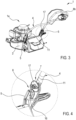
- Figures 1 to 4 show the mobile device in use conditions, in which the drive handle 4 is constrained to the frame 3 by means of the fastening element 5.
- the second groove 8 faces away from the land, so that the engagement of the coupling portion 11 of the handle 4 with the groove 8 of the fastening element 5 is facilitated by the action of the force of gravity.
- the fastening element 5 comprises a constraining portion 9, extending from the main body 6 along an extension direction D which is inclined with respect to the trajectory X by an internal angle ⁇ between 50° and 70°.
- the constraining portion 9 in turn has a plurality of holes 10, not aligned with each other (for example three holes arranged in a triangle), each of which is configured to allow the insertion of a bolt or a screw adapted to constrain the fastening element 5 to the frame 3.
- the constraining portion 9 emerges, for example laterally, from the main body 6 starting from the first or the second side 6a, 6b and is configured to engage, for example by interference, a tubular sleeve carried by the frame 3.
- the constraining portion 9 is free of holes 10 and has a cylindrical or tubular shape adapted to receive in insertion the sleeve (or adapted to insert into the sleeve) carried by the frame 3.
- the drive handle 4 of the mobile device 1 comprises the coupling portion 11, which is engageable to the fastening element 5 at least between a constraint condition (which ensures the stable engagement of the two parts 5 and 11 thus allowing the locking of the drive handle 4 with respect to the frame 3) and a release condition (which allows the disengagement of the handle 4 from the frame 3).
- a constraint condition which ensures the stable engagement of the two parts 5 and 11 thus allowing the locking of the drive handle 4 with respect to the frame 3
- a release condition which allows the disengagement of the handle 4 from the frame 3
- the coupling portion 11 has an elongated body, for example of tubular shape, extending along a predetermined extension direction, on which at least a first and a second locking pin 12, 13 are engaged, respectively configured to insert inside the second groove 8 and the first groove 7.
- the first and the second locking pin 12, 13 are aligned with each other and, in the illustrated example, are in particular along the extension direction of the elongated body of the coupling portion 11, so as to be able to be positioned inside the first groove 7 and the second stretch of the second groove 8.
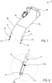
- the first and the second locking pin 12, 13 have a respective stretch 12a, 13a ( figure 8 ) emerging transversely with respect to the elongated body of the coupling portion 11: each stretch 12a, 13a is respectively configured to insert inside the first and the second groove 7, 8.
- the stretch 12a of the first locking pin 12 terminally carries a body or terminal expansion 16, having a radial dimension greater than the radial dimension of the stretch 12a and configured to prevent the extraction of the first locking pin 12 from the second groove along a direction parallel to the axis of the first pin 12.
- the first locking pin 12 can be inserted into the second groove 8 or removed from the second groove 8 only through the second access opening 8a since the stretch 12a has a radial dimension such as to slide in the second groove, while the body or expansion 16 has a minimum radial dimension greater than the maximum width of the second groove.
- the stretch 12a of the first locking pin 12, in the constraint condition of the fastening element 5, is thus inserted inside the second groove, while the body or expansion 16 remains outside the second groove acting in abutment on one of the opposite side surfaces of the main body.
- the second locking pin 13 has a respective stretch 13a of radial dimensions such as to insert and slide into the first groove (in practice, the second pin has a maximum radial dimension smaller than the width of the second groove).
- the coupling portion 11 further comprises a locking knob 17 configured to engage a threaded portion made on the stretch 13a of the second locking pin 13 and configured to constrain the coupling portion 11 to the fastening element 5.
- the stretch 13a of the second locking pin 13, in the constraint condition of the fastening element 5, is thus engaged within the first groove 7, while the main body of the coupling portion 11 and the locking knob 17 act in abutment on surfaces of the main body 6 opposite each other.
- the locking knob 17 is configured to permanently constrain the second locking pin 13 to the first groove, preventing any clearance between the coupling portion 11 and the main body 6 of the fastening element or plate 5.
- the device can comprise a plurality of coupling portions 11 and respective fastening elements 5 identical to what is described above; for example, in the illustrated embodiments, the drive handle 4 comprises a horizontal manoeuvring stretch at the second end 4b of the handle itself on which the user can act when he must push and/or direct the mobile device 1; the handle 4 comprises two distinct arms 4c extending, for example parallel or mirrored with each other, from the second end 4b towards the work unit 1a and each terminating in a respective coupling portion 11. In this case each coupling portion 11 of each arm 4c engages a respective fastening element 5 (in the case illustrated in the drawings there are therefore two fastening elements 5, one for each of the arms 4c of the handle 4) each of which is carried by the frame 3.
- the drive handle 4 comprises a horizontal manoeuvring stretch at the second end 4b of the handle itself on which the user can act when he must push and/or direct the mobile device 1;
- the handle 4 comprises two distinct arms 4c extending, for example parallel or
- a further object of the present invention is a procedure for mounting the mobile device in accordance with the description above and/or in accordance with any of the attached claims.
- the procedure comprises the steps of constraining the drive handle 4 to the frame 3 using the first and the second groove 7, 8 present on each of the fastening elements (or on the fastening element in the event of a handle 4 with only one arm 4c).
- the procedure includes constraining the coupling portion 11 of each arm 4c to the or to a respective fastening element 5.
- the constraining step comprises the sub-steps of:
- the step of arranging the second locking pin at the first opening includes resting such a second pin on the lip 20, thereby discharging the weight of the handle 4 on the frame 3 and thus on the ground.
- the procedure includes, following the step of inserting the second locking pin 13 inside the first groove 7, and after bringing both the first and the second pin at a bottom of the respective grooves, an engagement step between the threaded portion of the second locking pin 13 and the knob 17.
- figure 9 shows an example in which the fastening element 5, comprising the first and the second groove 7 and 8 as described above, is carried by the drive handle 4, while the coupling portion 11 is carried by the frame 3 (see figure 9 in this regard).
- the second access opening, during mounting is facing downwards and how the lip 20 is positioned so as to facilitate the mounting operations and the discharge of the weight of the handle 4 on the frame 3 and thus on the ground.
Landscapes
- Life Sciences & Earth Sciences (AREA)
- Environmental Sciences (AREA)
- Soil Working Implements (AREA)
- Snaps, Bayonet Connections, Set Pins, And Snap Rings (AREA)
- Vehicle Cleaning, Maintenance, Repair, Refitting, And Outriggers (AREA)
- Buildings Adapted To Withstand Abnormal External Influences (AREA)
Applications Claiming Priority (2)
| Application Number | Priority Date | Filing Date | Title |
|---|---|---|---|
| IT102021000022631A IT202100022631A1 (it) | 2021-08-31 | 2021-08-31 | Dispositivo di manutenzione di terreni |
| EP22185943.2A EP4140279B1 (de) | 2021-08-31 | 2022-07-20 | Befestigungselement zum ankuppeln des lenkers einer vorrichtung zur geländepflege |
Related Parent Applications (2)
| Application Number | Title | Priority Date | Filing Date |
|---|---|---|---|
| EP22185943.2A Division EP4140279B1 (de) | 2021-08-31 | 2022-07-20 | Befestigungselement zum ankuppeln des lenkers einer vorrichtung zur geländepflege |
| EP22185943.2A Division-Into EP4140279B1 (de) | 2021-08-31 | 2022-07-20 | Befestigungselement zum ankuppeln des lenkers einer vorrichtung zur geländepflege |
Publications (4)
| Publication Number | Publication Date |
|---|---|
| EP4223099A2 true EP4223099A2 (de) | 2023-08-09 |
| EP4223099A3 EP4223099A3 (de) | 2023-09-06 |
| EP4223099B1 EP4223099B1 (de) | 2025-11-19 |
| EP4223099C0 EP4223099C0 (de) | 2025-11-19 |
Family
ID=78649832
Family Applications (2)
| Application Number | Title | Priority Date | Filing Date |
|---|---|---|---|
| EP22185943.2A Active EP4140279B1 (de) | 2021-08-31 | 2022-07-20 | Befestigungselement zum ankuppeln des lenkers einer vorrichtung zur geländepflege |
| EP23165728.9A Active EP4223099B1 (de) | 2021-08-31 | 2022-07-20 | Mobile vorrichtung zur bodenpflege mit einem befestigungselement und verfahren zur montage solch einer vorrichtung |
Family Applications Before (1)
| Application Number | Title | Priority Date | Filing Date |
|---|---|---|---|
| EP22185943.2A Active EP4140279B1 (de) | 2021-08-31 | 2022-07-20 | Befestigungselement zum ankuppeln des lenkers einer vorrichtung zur geländepflege |
Country Status (3)
| Country | Link |
|---|---|
| EP (2) | EP4140279B1 (de) |
| IT (1) | IT202100022631A1 (de) |
| PL (1) | PL4140279T3 (de) |
Families Citing this family (1)
| Publication number | Priority date | Publication date | Assignee | Title |
|---|---|---|---|---|
| EP4740721A1 (de) * | 2024-11-07 | 2026-05-13 | Stiga S.P.A. | Manuell geführtes mobilgerät für die bodenpflege mit einem neigungsverstellbaren lenker |
Citations (3)
| Publication number | Priority date | Publication date | Assignee | Title |
|---|---|---|---|---|
| US2965386A (en) | 1956-11-16 | 1960-12-20 | Motor Wheel Corp | Lawn mower handle mounting structure |
| US20050188664A1 (en) | 2004-03-01 | 2005-09-01 | Clarke Khari S. | Walk-behind implement and handle assembly release apparatus for use with same |
| US20140260157A1 (en) | 2013-03-15 | 2014-09-18 | Husqvarna Ab | Door lift and handle for walk behind mower |
-
2021
- 2021-08-31 IT IT102021000022631A patent/IT202100022631A1/it unknown
-
2022
- 2022-07-20 PL PL22185943.2T patent/PL4140279T3/pl unknown
- 2022-07-20 EP EP22185943.2A patent/EP4140279B1/de active Active
- 2022-07-20 EP EP23165728.9A patent/EP4223099B1/de active Active
Patent Citations (3)
| Publication number | Priority date | Publication date | Assignee | Title |
|---|---|---|---|---|
| US2965386A (en) | 1956-11-16 | 1960-12-20 | Motor Wheel Corp | Lawn mower handle mounting structure |
| US20050188664A1 (en) | 2004-03-01 | 2005-09-01 | Clarke Khari S. | Walk-behind implement and handle assembly release apparatus for use with same |
| US20140260157A1 (en) | 2013-03-15 | 2014-09-18 | Husqvarna Ab | Door lift and handle for walk behind mower |
Also Published As
| Publication number | Publication date |
|---|---|
| EP4223099B1 (de) | 2025-11-19 |
| EP4140279A1 (de) | 2023-03-01 |
| IT202100022631A1 (it) | 2023-03-03 |
| EP4140279C0 (de) | 2025-04-02 |
| EP4223099A3 (de) | 2023-09-06 |
| EP4140279B1 (de) | 2025-04-02 |
| PL4140279T3 (pl) | 2025-08-04 |
| EP4223099C0 (de) | 2025-11-19 |
Similar Documents
| Publication | Publication Date | Title |
|---|---|---|
| US7204021B2 (en) | Multi-purpose plastic pipe cutter | |
| DE4104769C2 (de) | Zwingenwerkzeug | |
| EP4140279A1 (de) | Befestigungselement zum ankuppeln des lenkers einer vorrichtung zur geländepflege | |
| US7837413B1 (en) | Adjustable trench box and spreader bar | |
| US5282303A (en) | Fastener applying press method and dies therefor | |
| EP3703912B1 (de) | Stützzusatzeinrichtung für eine werkstückauflageeinrichtung | |
| US11279388B2 (en) | Cart system for securing and transporting on a cart any one of multiple portable tools | |
| DE10209096A1 (de) | Energiewerkzeug | |
| US4106645A (en) | Means for quick attachment of implement to a tractor | |
| DE102005050783A1 (de) | Vorrichtung mit einer Profilschiene und mit wenigstens einem Befestigungselement | |
| US11001287B2 (en) | Cart system for securing and transporting a portable tool | |
| EP3027334B1 (de) | Spannsystem für verbindungsstange | |
| US11471956B2 (en) | Tool device and reaction bar | |
| US20140033522A1 (en) | Apparatus, system, and method for removing and installing a continuous track on a machine | |
| EP2308651A1 (de) | Hand-Werkzeugmachine mit einem Haken | |
| US4188754A (en) | Portable cutter | |
| DE19621877C2 (de) | Preßzange | |
| CA2710258C (en) | Portable direct action brittle pipe/soil pipe cutter | |
| WO2023023344A1 (en) | Apparatus and method for spreading wheel lock ring | |
| KR101813059B1 (ko) | 조립 및 해체가 용이한 톱니형 체결 수단이 구비된 회전 개폐식 분기관 연결구 및 연결구 기계적 압착 체결과 해체 겸용 공구 | |
| US5626045A (en) | Metal stock bender | |
| US20050173853A1 (en) | Portable vise | |
| US6941840B1 (en) | Multiple nut tool and method | |
| CN111230208A (zh) | 用于剪切操作的工具头 | |
| US20220219298A1 (en) | Assembly device and method for assembling components |
Legal Events
| Date | Code | Title | Description |
|---|---|---|---|
| PUAI | Public reference made under article 153(3) epc to a published international application that has entered the european phase |
Free format text: ORIGINAL CODE: 0009012 |
|
| STAA | Information on the status of an ep patent application or granted ep patent |
Free format text: STATUS: THE APPLICATION HAS BEEN PUBLISHED |
|
| PUAL | Search report despatched |
Free format text: ORIGINAL CODE: 0009013 |
|
| AC | Divisional application: reference to earlier application |
Ref document number: 4140279 Country of ref document: EP Kind code of ref document: P |
|
| AK | Designated contracting states |
Kind code of ref document: A2 Designated state(s): AL AT BE BG CH CY CZ DE DK EE ES FI FR GB GR HR HU IE IS IT LI LT LU LV MC MK MT NL NO PL PT RO RS SE SI SK SM TR |
|
| AK | Designated contracting states |
Kind code of ref document: A3 Designated state(s): AL AT BE BG CH CY CZ DE DK EE ES FI FR GB GR HR HU IE IS IT LI LT LU LV MC MK MT NL NO PL PT RO RS SE SI SK SM TR |
|
| RIC1 | Information provided on ipc code assigned before grant |
Ipc: A01D 34/67 20060101ALI20230728BHEP Ipc: A01D 34/82 20060101AFI20230728BHEP |
|
| STAA | Information on the status of an ep patent application or granted ep patent |
Free format text: STATUS: REQUEST FOR EXAMINATION WAS MADE |
|
| 17P | Request for examination filed |
Effective date: 20240109 |
|
| RBV | Designated contracting states (corrected) |
Designated state(s): AL AT BE BG CH CY CZ DE DK EE ES FI FR GB GR HR HU IE IS IT LI LT LU LV MC MK MT NL NO PL PT RO RS SE SI SK SM TR |
|
| GRAP | Despatch of communication of intention to grant a patent |
Free format text: ORIGINAL CODE: EPIDOSNIGR1 |
|
| STAA | Information on the status of an ep patent application or granted ep patent |
Free format text: STATUS: GRANT OF PATENT IS INTENDED |
|
| INTG | Intention to grant announced |
Effective date: 20250321 |
|
| GRAJ | Information related to disapproval of communication of intention to grant by the applicant or resumption of examination proceedings by the epo deleted |
Free format text: ORIGINAL CODE: EPIDOSDIGR1 |
|
| STAA | Information on the status of an ep patent application or granted ep patent |
Free format text: STATUS: REQUEST FOR EXAMINATION WAS MADE |
|
| GRAP | Despatch of communication of intention to grant a patent |
Free format text: ORIGINAL CODE: EPIDOSNIGR1 |
|
| STAA | Information on the status of an ep patent application or granted ep patent |
Free format text: STATUS: GRANT OF PATENT IS INTENDED |
|
| INTC | Intention to grant announced (deleted) | ||
| INTG | Intention to grant announced |
Effective date: 20250616 |
|
| GRAS | Grant fee paid |
Free format text: ORIGINAL CODE: EPIDOSNIGR3 |
|
| GRAA | (expected) grant |
Free format text: ORIGINAL CODE: 0009210 |
|
| STAA | Information on the status of an ep patent application or granted ep patent |
Free format text: STATUS: THE PATENT HAS BEEN GRANTED |
|
| AC | Divisional application: reference to earlier application |
Ref document number: 4140279 Country of ref document: EP Kind code of ref document: P |
|
| AK | Designated contracting states |
Kind code of ref document: B1 Designated state(s): AL AT BE BG CH CY CZ DE DK EE ES FI FR GB GR HR HU IE IS IT LI LT LU LV MC MK MT NL NO PL PT RO RS SE SI SK SM TR |
|
| REG | Reference to a national code |
Ref country code: CH Ref legal event code: F10 Free format text: ST27 STATUS EVENT CODE: U-0-0-F10-F00 (AS PROVIDED BY THE NATIONAL OFFICE) Effective date: 20251119 Ref country code: GB Ref legal event code: FG4D |
|
| REG | Reference to a national code |
Ref country code: DE Ref legal event code: R096 Ref document number: 602022025442 Country of ref document: DE |
|
| REG | Reference to a national code |
Ref country code: IE Ref legal event code: FG4D |
|
| U01 | Request for unitary effect filed |
Effective date: 20251219 |
|
| U07 | Unitary effect registered |
Designated state(s): AT BE BG DE DK EE FI FR IT LT LU LV MT NL PT RO SE SI Effective date: 20260105 |
|
| PG25 | Lapsed in a contracting state [announced via postgrant information from national office to epo] |
Ref country code: ES Free format text: LAPSE BECAUSE OF FAILURE TO SUBMIT A TRANSLATION OF THE DESCRIPTION OR TO PAY THE FEE WITHIN THE PRESCRIBED TIME-LIMIT Effective date: 20251119 |
|
| PG25 | Lapsed in a contracting state [announced via postgrant information from national office to epo] |
Ref country code: NO Free format text: LAPSE BECAUSE OF FAILURE TO SUBMIT A TRANSLATION OF THE DESCRIPTION OR TO PAY THE FEE WITHIN THE PRESCRIBED TIME-LIMIT Effective date: 20260219 |
|
| PG25 | Lapsed in a contracting state [announced via postgrant information from national office to epo] |
Ref country code: HR Free format text: LAPSE BECAUSE OF FAILURE TO SUBMIT A TRANSLATION OF THE DESCRIPTION OR TO PAY THE FEE WITHIN THE PRESCRIBED TIME-LIMIT Effective date: 20251119 |
|
| PG25 | Lapsed in a contracting state [announced via postgrant information from national office to epo] |
Ref country code: RS Free format text: LAPSE BECAUSE OF FAILURE TO SUBMIT A TRANSLATION OF THE DESCRIPTION OR TO PAY THE FEE WITHIN THE PRESCRIBED TIME-LIMIT Effective date: 20260219 |
|
| PG25 | Lapsed in a contracting state [announced via postgrant information from national office to epo] |
Ref country code: IS Free format text: LAPSE BECAUSE OF FAILURE TO SUBMIT A TRANSLATION OF THE DESCRIPTION OR TO PAY THE FEE WITHIN THE PRESCRIBED TIME-LIMIT Effective date: 20260319 |
|
| PG25 | Lapsed in a contracting state [announced via postgrant information from national office to epo] |
Ref country code: PL Free format text: LAPSE BECAUSE OF FAILURE TO SUBMIT A TRANSLATION OF THE DESCRIPTION OR TO PAY THE FEE WITHIN THE PRESCRIBED TIME-LIMIT Effective date: 20251119 |