EP4221480B1 - Power adapter - Google Patents
Power adapter Download PDFInfo
- Publication number
- EP4221480B1 EP4221480B1 EP23153660.8A EP23153660A EP4221480B1 EP 4221480 B1 EP4221480 B1 EP 4221480B1 EP 23153660 A EP23153660 A EP 23153660A EP 4221480 B1 EP4221480 B1 EP 4221480B1
- Authority
- EP
- European Patent Office
- Prior art keywords
- power adapter
- end wall
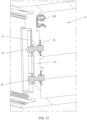
- sealing
- fastened
- guide connector
- Prior art date
- Legal status (The legal status is an assumption and is not a legal conclusion. Google has not performed a legal analysis and makes no representation as to the accuracy of the status listed.)
- Active
Links
Images







Classifications
-
- H—ELECTRICITY
- H02—GENERATION; CONVERSION OR DISTRIBUTION OF ELECTRIC POWER
- H02M—APPARATUS FOR CONVERSION BETWEEN AC AND AC, BETWEEN AC AND DC, OR BETWEEN DC AND DC, AND FOR USE WITH MAINS OR SIMILAR POWER SUPPLY SYSTEMS; CONVERSION OF DC OR AC INPUT POWER INTO SURGE OUTPUT POWER; CONTROL OR REGULATION THEREOF
- H02M1/00—Details of apparatus for conversion
-
- H—ELECTRICITY
- H05—ELECTRIC TECHNIQUES NOT OTHERWISE PROVIDED FOR
- H05K—PRINTED CIRCUITS; CASINGS OR CONSTRUCTIONAL DETAILS OF ELECTRIC APPARATUS; MANUFACTURE OF ASSEMBLAGES OF ELECTRICAL COMPONENTS
- H05K7/00—Constructional details common to different types of electric apparatus
- H05K7/20—Modifications to facilitate cooling, ventilating, or heating
- H05K7/20218—Modifications to facilitate cooling, ventilating, or heating using a liquid coolant without phase change in electronic enclosures
- H05K7/20236—Modifications to facilitate cooling, ventilating, or heating using a liquid coolant without phase change in electronic enclosures by immersion
-
- H—ELECTRICITY
- H01—ELECTRIC ELEMENTS
- H01R—ELECTRICALLY-CONDUCTIVE CONNECTIONS; STRUCTURAL ASSOCIATIONS OF A PLURALITY OF MUTUALLY-INSULATED ELECTRICAL CONNECTING ELEMENTS; COUPLING DEVICES; CURRENT COLLECTORS
- H01R13/00—Details of coupling devices of the kinds covered by groups H01R12/70 or H01R24/00 - H01R33/00
- H01R13/66—Structural association with built-in electrical component
- H01R13/665—Structural association with built-in electrical component with built-in electronic circuit
- H01R13/6675—Structural association with built-in electrical component with built-in electronic circuit with built-in power supply
-
- H—ELECTRICITY
- H01—ELECTRIC ELEMENTS
- H01R—ELECTRICALLY-CONDUCTIVE CONNECTIONS; STRUCTURAL ASSOCIATIONS OF A PLURALITY OF MUTUALLY-INSULATED ELECTRICAL CONNECTING ELEMENTS; COUPLING DEVICES; CURRENT COLLECTORS
- H01R13/00—Details of coupling devices of the kinds covered by groups H01R12/70 or H01R24/00 - H01R33/00
- H01R13/46—Bases; Cases
- H01R13/52—Dustproof, splashproof, drip-proof, waterproof, or flameproof cases
- H01R13/5202—Sealing means between parts of housing or between housing part and a wall, e.g. sealing rings
-
- H—ELECTRICITY
- H01—ELECTRIC ELEMENTS
- H01R—ELECTRICALLY-CONDUCTIVE CONNECTIONS; STRUCTURAL ASSOCIATIONS OF A PLURALITY OF MUTUALLY-INSULATED ELECTRICAL CONNECTING ELEMENTS; COUPLING DEVICES; CURRENT COLLECTORS
- H01R24/00—Two-part coupling devices, or either of their cooperating parts, characterised by their overall structure
- H01R24/28—Coupling parts carrying pins, blades or analogous contacts and secured only to wire or cable
-
- H—ELECTRICITY
- H05—ELECTRIC TECHNIQUES NOT OTHERWISE PROVIDED FOR
- H05K—PRINTED CIRCUITS; CASINGS OR CONSTRUCTIONAL DETAILS OF ELECTRIC APPARATUS; MANUFACTURE OF ASSEMBLAGES OF ELECTRICAL COMPONENTS
- H05K5/00—Casings, cabinets or drawers for electric apparatus
- H05K5/02—Details
- H05K5/0247—Electrical details of casings, e.g. terminals, passages for cables or wiring
-
- H—ELECTRICITY
- H05—ELECTRIC TECHNIQUES NOT OTHERWISE PROVIDED FOR
- H05K—PRINTED CIRCUITS; CASINGS OR CONSTRUCTIONAL DETAILS OF ELECTRIC APPARATUS; MANUFACTURE OF ASSEMBLAGES OF ELECTRICAL COMPONENTS
- H05K5/00—Casings, cabinets or drawers for electric apparatus
- H05K5/06—Hermetically-sealed casings
- H05K5/061—Hermetically-sealed casings sealed by a gasket held between a removable cover and a body, e.g. O-ring, packing
-
- H—ELECTRICITY
- H05—ELECTRIC TECHNIQUES NOT OTHERWISE PROVIDED FOR
- H05K—PRINTED CIRCUITS; CASINGS OR CONSTRUCTIONAL DETAILS OF ELECTRIC APPARATUS; MANUFACTURE OF ASSEMBLAGES OF ELECTRICAL COMPONENTS
- H05K7/00—Constructional details common to different types of electric apparatus
- H05K7/20—Modifications to facilitate cooling, ventilating, or heating
- H05K7/20218—Modifications to facilitate cooling, ventilating, or heating using a liquid coolant without phase change in electronic enclosures
-
- H—ELECTRICITY
- H05—ELECTRIC TECHNIQUES NOT OTHERWISE PROVIDED FOR
- H05K—PRINTED CIRCUITS; CASINGS OR CONSTRUCTIONAL DETAILS OF ELECTRIC APPARATUS; MANUFACTURE OF ASSEMBLAGES OF ELECTRICAL COMPONENTS
- H05K7/00—Constructional details common to different types of electric apparatus
- H05K7/20—Modifications to facilitate cooling, ventilating, or heating
- H05K7/2089—Modifications to facilitate cooling, ventilating, or heating for power electronics, e.g. for inverters for controlling motor
- H05K7/20927—Liquid coolant without phase change
-
- H—ELECTRICITY
- H01—ELECTRIC ELEMENTS
- H01R—ELECTRICALLY-CONDUCTIVE CONNECTIONS; STRUCTURAL ASSOCIATIONS OF A PLURALITY OF MUTUALLY-INSULATED ELECTRICAL CONNECTING ELEMENTS; COUPLING DEVICES; CURRENT COLLECTORS
- H01R2103/00—Two poles
Definitions
- This application relates to the technical field of power adapters, and in particular, to a power adapter.
- a power adapter is a power supply conversion device for portable electronic devices and electronic and electrical appliances, and is usually used for small electronic products such as a mobile phone and a notebook computer.
- a power adapter With the progress of science and technology, users using mobile phones gradually pursue a power adapter with a higher charging speed and a smaller volume. Therefore, high power and miniaturization have become one of key selling points of power adapters in the market, and also become one of core competitiveness of brands.
- US 2017/094842 A1 discloses a power supply including a casing enclosing a circuit for power conversion including one or more heat generating electronic components mounted on a circuit board, an input port configured to receive electrical energy from a power source, an output port configured to supply electrical energy to an external load, and a dielectric liquid disposed in the casing.
- US 2020/107469 A1 discloses a wireless charging device with a heat dissipation function including a case, a wireless charging assembly and a working fluid.
- the case includes an accommodation space.
- the wireless charging assembly is disposed in the accommodation space.
- Embodiments of this application provide a power adapter, and the power adapter in this application has a good heat dissipation effect.
- a power adapter includes a housing body, a rear cover, a circuit board assembly, a first guide connector, a second guide connector, and a thermally conductive liquid.
- the housing body has an opening, the rear cover is fastened to the housing body and covers the opening, the housing body and the rear cover are connected in a sealed manner and enclose to form an accommodating cavity, the circuit board assembly is disposed in the accommodating cavity, the thermally conductive liquid fills the accommodating cavity and wraps the circuit board assembly, the housing body includes a front end wall disposed opposite to the rear cover, the first guide connector is mounted on the front end wall and connected to the front end wall in a sealed manner, the second guide connector is mounted on the rear cover and is connected to the rear cover in a sealed manner, and both the first guide connector and the second guide connector are electrically connected to the circuit board assembly.
- a related technology implements even heat distribution in the following three manners.
- heat generated by the circuit board assembly is dissipated from a high-temperature area to a low-temperature area through air inside the power adapter, so that an even heat distribution effect is achieved inside the power adapter.
- a heat dissipation speed is low, and a local temperature is excessively high. Therefore, high-temperature overload protection of components of the circuit board assembly is caused and the components stop operating.
- a potting adhesive is injected into the power adapter, and is used in place of air as a medium for transferring heat, so that an even heat distribution effect is achieved inside the power adapter.
- the injected potting adhesive will affect electromagnetic compatibility of the components of the circuit board assembly.
- a thermally conductive white adhesive is applied around the components generating a high temperature of the circuit board assembly, to achieve fastening and thermal conduction effects, increase a heat dissipation area, and transfer heat, so that the components achieve an even heat distribution effect.
- a curing time of the white adhesive is long, and it is difficult to control a dispensing range and easy to pollute the components.
- the housing body and the rear cover enclose to form the accommodating cavity, the housing body and the rear cover are connected in a sealed manner, the thermally conductive liquid can fill the accommodating cavity and wrap the circuit board assembly, and both the first guide connector and the second guide connector are connected to the housing in a sealed manner to ensure that the thermally conductive liquid does not leak.
- heat emitted by the circuit board assembly during operation may be quickly transferred from a high-temperature side to a low-temperature side through the thermally conductive liquid to implement even heat distribution, thereby improving heat dissipation efficiency of the power adapter.
- this application does not affect electric performance of the circuit board assembly, ensuring a heat dissipation effect of the power adapter with a high power and a small size. Therefore, the size of the power adapter may be as small as possible when performance permits, thereby improving user experience.
- the first guide connector includes a first connecting portion, a second connecting portion, and an adapting portion
- the front end wall includes a first surface and a second surface disposed opposite to each other, the second surface faces toward the accommodating cavity
- the first connecting portion is fastened on the first surface
- the second connecting portion is fastened on the second surface and electrically connected to the circuit board assembly
- the adapting portion penetrates through the front end wall and is electrically connected to each of the first connecting portion and the second connecting portion
- the adapting portion is connected to the front end wall in a sealed manner to ensure airtightness of the accommodating cavity.
- the adapting portion is fastened on the front end wall through insert molding. It may be understood that, the adapting portion being fastened on the front end wall through insert molding, on one hand, can ensure a sealing effect between the adapting portion and the front end wall, and on the other hand, improves manufacturing efficiency of a product by omitting a step of mounting the adapting portion on the front end wall.
- the adapting portion may alternatively be mounted on the front end wall, and a gap between the adapting portion and the front end wall may be sealed by using a sealing material.
- the first connecting portion is a pin.
- the power adapter further includes a front cover, pins are provided on the front cover, the pins penetrate through two opposite surfaces of the front cover, the front cover is fastened on the front end wall, and the pins are connected to the first guide connector.
- the pins need to be plugged and unplugged in a process of connecting to the external power supply, and a gap occurs between the pins and the front cover under a force during plugging and unplugging of the pins. If the pins are directly fastened on the front end wall of the housing body, a gap occurs between the pins and the front end wall during plugging and unplugging of the pins, and the thermally conductive liquid in the accommodating cavity will leak out through the gap.
- the first guide connector is provided on the front end wall in this application, and the pins are connected to the first guide connector, that is, the pins are separated from the housing body, so that leakage of the thermally conductive liquid can be avoided even if a gap occurs between the pins and the front cover during plugging and unplugging of the pins.
- the front end wall includes a sealing groove, and the sealing groove is disposed around the first guide connector.
- the power adapter further includes a second sealing kit, and the second sealing kit is disposed between the sealing groove and the front cover.
- the sealing groove is configured to accommodate and fasten the second sealing kit, to ensure that the second sealing kit is stably fastened between the front end wall and the front cover.
- the second sealing kit is disposed between the sealing groove and the front cover to seal a gap between the front end wall and the front cover. In this embodiment, airtightness of the accommodating cavity is improved through several layers of sealing.
- the front end wall is provided with a liquid injection hole, through which the thermally conductive liquid is filled into the accommodating cavity.
- the liquid injection hole is provided in the front end wall, so that during assembly of the power adapter, the circuit board assembly may be fastened inside the housing body, then the rear cover is fastened to the housing body and sealed with the housing body, and finally, the thermally conductive liquid is filled into the accommodating cavity through the liquid injection hole.
- the operation in this embodiment is more convenient, and the thermally conductive liquid can be more fully filled into the accommodating cavity, thereby achieving a better heat dissipation effect.
- the power adapter further includes a sealing cap, and the sealing cap is fastened to the liquid injection hole, to prevent the thermally conductive liquid filled into the accommodating cavity from overflowing from the liquid injection hole, thereby ensuring airtightness of the accommodating cavity.
- the power adapter further includes a front cover, and the front cover is fastened on the front end wall.
- a surface that is of the sealing cap and that faces away from the liquid injection hole abuts against the front cover.
- the cover body also has a position limiting effect on the sealing cap, to prevent the sealing cap from loosening from the liquid injection hole and an exhaust hole and ensure airtightness of the accommodating cavity.
- the power adapter further includes an exhaust hole, and the exhaust hole is provided in the front end wall and is connected to the accommodating cavity.
- the exhaust hole is provided, so that when the thermally conductive liquid is filled through the liquid injection hole into the accommodating cavity, air in the accommodating cavity may be discharged from the exhaust hole in time. In this way, a speed of filling the thermally conductive liquid into the accommodating cavity is not hindered, efficient filling of the thermally conductive liquid is implemented, and manufacturing efficiency of a product is improved.
- the power adapter further includes a third sealing kit
- the rear cover is provided with an insertion hole
- the second guide connector is fastened to the insertion hole
- the second guide connector and a hole wall of the insertion hole are sealed by using the third sealing kit, to prevent the thermally conductive liquid in the accommodating cavity from leaking out from a gap between the second guide connector and the insertion hole, thereby ensuring airtightness of the accommodating cavity.
- connection may a detachable connection or a non-detachable connection, or may be a direct connection or an indirect connection via an intermediate medium.
- connection refers to mutual connection and relative positions remain unchanged after the connection.
- Orientation terms mentioned in the embodiments of this application such as, “front”, “rear”, “inside”, and “outside”, are merely orientations with reference to the accompanying drawings.
- orientation terms are used to better and more clearly describe and understand the embodiments of this application, rather than to indicate or imply that an apparatus or a component needs to have a specific orientation, or be constructed and operated in a specific orientation. Therefore, these orientation terms cannot be construed as a limitation on the embodiments of this application. "A plurality of" means at least two.
- FIG. 1 is a schematic diagram of a structure of a power adapter 100 according to an embodiment of this application.
- the power adapter 100 may be an adapter for various electronic devices and electronic and electrical appliances, may be a consumer electronic product, or may be another device for a server or a data center.
- the power adapter 100 includes but is not limited to a mobile phone power adapter, an iPad power adapter, a power adapter for a notebook/gaming laptop, a car charger, or the like.
- the power adapter 100 being a mobile phone power adapter is used as an example in FIG. 1 for specific description.
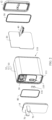
- FIG. 2 is a schematic exploded diagram of the power adapter 100 shown in FIG. 1 .
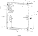
- FIG. 3 is a schematic diagram of a cross-sectional structure, in A-A direction, of the power adapter 100 shown in FIG. 1 .
- the power adapter 100 may include a housing 10, a circuit board assembly 20, a first guide connector 30, a second guide connector 40, a first sealing kit 50, and a thermally conductive liquid (which is not shown in the figure).
- the housing 10 may include a housing body 11 and a rear cover 12, where the housing body 11 has an opening 110, the rear cover 12 is fastened to the housing body 11 and covers the opening 110, the housing body 11 and the rear cover 12 are connected in a sealed manner and enclose to form an accommodating cavity 13, the circuit board assembly 20 is provided in the accommodating cavity 13, the thermally conductive liquid fills the accommodating cavity 13 and wraps the circuit board assembly 20, the housing body 11 includes a front end wall 111 disposed opposite to the rear cover 12, the first guide connector 30 is mounted on the front end wall 111 and is connected to the front end wall 111 in a sealed manner, the second guide connector 40 is mounted on the rear cover 12 and is connected to the rear cover 12 in a sealed manner, and both the first guide connector 30 and the second guide connector 40 are electrically connected to the circuit
- a related technology implements even heat distribution in the following three manners.
- heat generated by the circuit board assembly is dissipated from a high-temperature area to a low-temperature area through air inside the power adapter, so that an even heat distribution effect is achieved inside the power adapter.
- a heat dissipation speed is low, and a local temperature is excessively high. Therefore, high-temperature overload protection of components of the circuit board assembly is caused and the components stop operating.
- a potting adhesive is injected into the power adapter, and is used in place of air as a medium for transferring heat, so that an even heat distribution effect is achieved inside the power adapter.
- the injected potting adhesive will affect electromagnetic compatibility of the components of the circuit board assembly.
- a thermally conductive white adhesive is applied around the components generating a high temperature, of the circuit board assembly, to achieve fastening and thermal conduction effects, increase a heat dissipation area, and transfer heat, so that the components achieve an even heat distribution effect.
- a curing time of the white adhesive is long, it is difficult to control a dispensing range, and the components are easily polluted.
- the housing body 11 and the rear cover 12 enclose to form the accommodating cavity 13, the housing body 11 and the rear cover 12 are connected in a sealed manner, the thermally conductive liquid can fill the accommodating cavity 13 and wrap the circuit board assembly 20, and both the first guide connector 30 and the second guide connector 40 are connected to the housing 10 in a sealed manner to ensure that the thermally conductive liquid does not leak.
- heat emitted by the circuit board assembly 20 during operation may be quickly transferred from a high-temperature side to a low-temperature side through the thermally conductive liquid to implement even heat distribution, thereby improving heat dissipation efficiency of the power adapter 100.
- this application does not affect electric performance of the circuit board assembly 20, ensuring a heat dissipation effect of the power adapter 100 with a high power and a small size. Therefore, the size of the power adapter 100 may be as small as possible when performance permits, thereby improving user experience.
- the thermally conductive liquid is an insulation liquid with a strong heat absorption capability, and presents an excellent thermally conductive effect without affecting electrical performance of the circuit board assembly 20, so that a heat dissipation effect of the power adapter 100 is improved.
- the thermally conductive liquid may be an oil liquid, for example, lubricating oil for a speed reducer.
- the power adapter 100 includes a first sealing kit 50, where the first sealing kit 50 is disposed between the rear cover 12 and the housing body 11 to seal the accommodating cavity 13, that is, the housing body 11 and the rear cover 12 are connected in a sealed manner by the first sealing kit 50.
- the first sealing kit 50 is disposed between the rear cover 12 and the housing body 11 to seal the accommodating cavity 13, that is, the housing body 11 and the rear cover 12 are connected in a sealed manner by the first sealing kit 50.
- another material may be used for sealed connection between the housing body 11 and the rear cover 12.
- the housing body 11 and the rear cover 12 may be connected through ultrasonic welding.
- the first sealing kit 50 is compressed during ultrasonic welding for connection between the housing body 11 and the rear cover 12, so that the first sealing kit 50 fills a gap between the housing body 11 and the rear cover 12, thereby effectively improving airtightness of the accommodating cavity 13.
- the housing body 11 and the rear cover 12 may be connected in another manner. This is not limited in this application.
- the first sealing kit 50 may be a sealing ring. It may be understood that it is easier to fit a sealing ring between the housing body 11 and the rear cover 12 than another sealing material. Certainly, in another embodiment, the first sealing kit 50 may be another sealing material such as a sealing adhesive.
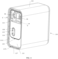
- FIG. 4 is a schematic diagram of a structure of the housing body 11 and the first guide connector 30 in the structure shown in FIG. 2 .
- the housing body 11 is cuboid.
- the housing body 11 further includes a peripheral side wall 112 connected to and disposed around the periphery of the front end wall 111, and an opening 110 is provided on a side that is of the peripheral side wall 112 and that faces away from the front end wall 111.
- One end that is of the peripheral side wall 112 and that is far away from the front end wall 111 is fastened to the rear cover 12.
- the front end wall 111, the peripheral side wall 112, and the rear cover 12 jointly enclose to form the accommodating cavity 13.
- the housing body 11 may alternatively be cylindrical, cubic, or the like.
- the front end wall 111 includes a first surface 1111 and a second surface 1112 disposed opposite to each other, where the first surface 1111 faces away from the accommodating cavity 13, and the second surface 1112 faces toward the accommodating cavity 13.
- the first surface 1111 is provided with a mounting groove 113, and the first guide connector 30 is mounted in the mounting groove 113. It may be understood that when the first guide connector 30 is mounted in the mounting groove 113, the first guide connector 30 and the front end wall 111 have overlapping portions in a thickness direction of the front end wall 111. Such manner can miniaturize the power adapter 100 in the thickness direction of the front end wall 111 compared with a manner of directly mounting the first guide connector 30 on the first surface 1111.
- the first surface 1111 may not be provided with a mounting groove, and the first guide connector 30 may be directly mounted on the first surface 1111.
- the front end wall 111 is provided with a liquid injection hole 114, where the liquid injection hole 114 penetrates through the front end wall 111 and is connected to the accommodating cavity 13, and the liquid injection hole 114 and the mounting groove 113 are spaced apart.
- the thermally conductive liquid is filled into the accommodating cavity 13 through the liquid injection hole 114.
- the liquid injection hole 114 is provided in the front end wall 111, so that during assembly of the power adapter 100, the circuit board assembly 20 may be fastened inside the housing body 11, then the rear cover 12 is fastened to the housing body 11 and sealed with the housing body 11, and finally, the thermally conductive liquid is filled into the accommodating cavity 13 through the liquid injection hole 114.
- the operation in this embodiment is more convenient, and the thermally conductive liquid can be more fully filled into the accommodating cavity 13, thereby achieving a better heat dissipation effect.
- the front end wall 111 may not be provided with a liquid injection hole, and the thermally conductive liquid is filled into the accommodating cavity 13 before the rear cover 12 is fastened to the housing body 11.
- liquid injection hole 114 there is one liquid injection hole 114 in this embodiment, and the liquid injection hole 114 is circular.
- the liquid injection hole 114 may be circular, star-shaped, square, or irregular in shape.
- the power adapter 100 further includes an exhaust hole 115, and the exhaust hole 115 is provided formed in the front end wall 111 and is connected to the accommodating cavity 13.
- the exhaust hole 115 is provided adjacent to the liquid injection hole 114.
- the exhaust hole 115 is provided, so that when the thermally conductive liquid is filled through the liquid injection hole 114 into the accommodating cavity 13, air in the accommodating cavity 13 may be discharged from the exhaust hole 115 in time. In this way, a speed of filling the thermally conductive liquid into the accommodating cavity 13 is not hindered, efficient filling of the thermally conductive liquid is implemented, and manufacturing efficiency of a product is improved.
- the exhaust hole 115 and the liquid injection hole 114 have a same diameter, to ensure efficient filling of the thermally conductive liquid.
- the power adapter 100 may not include an exhaust hole.
- the exhaust hole 115 may alternatively be disposed at the edge of the liquid injection hole 114 and is connected to the liquid injection hole 114.
- the exhaust hole 115 and the liquid injection hole 114 may have different diameters.
- exhaust hole 115 there is one exhaust hole 115 in this embodiment, and the exhaust hole 115 is circular.
- the exhaust hole 115 may be a plurality of exhaust holes 115, which may be in a same shape or in different shapes.
- the exhaust hole 115 may be circular, star-shaped, square, or irregular in shape.
- the power adapter 100 further includes sealing caps 116 for respectively sealing the liquid injection hole 114 and the exhaust hole 115.
- sealing caps 116 there are two sealing caps 116, one of which is fastened to the liquid injection hole 114 to seal the liquid injection hole 114, and the other one is fastened to the exhaust hole 115 to seal the exhaust hole 115. This prevents the thermally conductive liquid filled into the accommodating cavity 13 from overflowing from the liquid injection hole 114 and the exhaust hole 115, and ensures airtightness of the accommodating cavity 13.
- a quantity of sealing caps 116 is not limited to two, and the quantity of sealing caps 116 corresponds to a total quantity of exhaust holes 115 and liquid injection holes 114.
- the power adapter 100 may not include a sealing cap, and a sealing material may be used to seal the liquid injection hole 114 and the exhaust hole 115 after the thermally conductive liquid is filled into the accommodating cavity 13.
- the first surface 1111 may further be provided with a fixed structure to limit positions of the sealing caps 116, to prevent the sealing caps 116 from loosening from the liquid injection hole 114 or the exhaust hole 115.
- FIG. 5 is a schematic diagram of the structure shown in FIG. 4 from another angle.
- the peripheral side wall 112 includes an end portion that is far away from the front end wall 111, and an outer side of the end portion is provided with a fitting groove 1121, where the fitting groove 1121 is configured to fit the rear cover 12.
- the fitting groove 1121 is configured to accommodate a portion that is of the rear cover 12 and that is connected to the peripheral side wall 112, to perform a position limiting effect on the rear cover 12, so that the rear cover 12 is stably fastened to the peripheral side wall 112.
- the fitting groove 1121 facilitates quick matching between the rear cover 12 and the peripheral side wall 112, so that the rear cover 12 is quickly mounted on the peripheral side wall 112.
- the outer side of the end portion may not be provided with a fitting groove, and the end portion is directly fixedly connected to the rear cover 12.
- An inner side of the end portion is provided with an abutting groove 1122, and the abutting groove 1122 is configured to accommodate the first sealing kit 50 in cooperation with the rear cover 12, to make the first sealing kit 50 be located between the abutting groove 1122 and the rear cover 12 and stably located between the peripheral side wall 112 and the rear cover 12, thereby ensuring airtightness of the accommodating cavity 13.
- the inner side of the end portion may not be provided with an abutting groove, and the first sealing kit 50 may be directly fastened between the end portion and the rear cover 12.
- FIG. 6 is a diagram of a cross-sectional structure, in direction B-B, of the structure shown in FIG. 1 .
- the peripheral side wall 112 includes a first side wall 1123 and a second side wall 1124 disposed oppositely.
- a first fastening portion 1125 and a second fastening portion 1126 are respectively provided on surfaces, of the first side wall 1123 and the second side wall 1124, facing toward the accommodating cavity 13.
- the first fastening portion 1125 and the second fastening portion 1126 are disposed oppositely.
- One end of the circuit board assembly 20 is fastened to the first fastening portion 1125, and the other end is fastened to the second fastening portion 1126, to stably fasten the circuit board assembly 20 inside the housing body 11.
- the circuit board assembly 20 may alternatively be directly fastened on the peripheral side wall 112.
- the first fastening portion 1125 is provided with a first slot 251
- the second fastening portion 1126 is provided with a second slot 261, so that one end of the circuit board assembly 20 may be inserted into the first slot 251, and the other end may be inserted into the second slot 261.
- the circuit board assembly 20 can be securely fastened inside the housing body 11, and an overall strength of the power adapter 100 can be increased.
- the manner of fastening the circuit board assembly 20 by inserting the circuit board assembly 20 into the slots is simpler and easy for assembly, thereby effectively improving manufacturing efficiency.
- first side wall 1123 and the second side wall 1124 may not be provided with fastening portions, and the first slot 251 and the second slot 261 may be respectively provided on the first side wall 1123 and the second side wall 1124.
- the circuit board assembly 20 may be fastened inside the housing body 11 in another manner. This is not limited in this application.
- FIG. 7 is a schematic diagram of a structure of the rear cover 12 in the structure shown in FIG. 2 .
- the rear cover 12 may include a plate body 121 and a connecting portion 122.
- the plate body 121 includes a first surface 1211 and a second surface 1212 that are disposed oppositely, and the connecting portion 122 is disposed around the periphery of the second surface 1212.
- the connecting portion 122 is configured to fit the housing body 11, to implement a fixed connection between the rear cover 12 and the housing body 11.
- the rear cover 12 may include only the plate body 121, but not include the connecting portion, and the plate body 121 may be directly fastened to the housing body 11.
- the rear cover 12 is provided with an insertion hole 123, the insertion hole 123 penetrates through two opposite surfaces of the plate body 121, and the second guide connector 40 is fastened to the insertion hole 123.
- the second surface 1112 is further provided with two screw posts 124, where the two screw posts 124 are respectively provided on two opposite sides of the insertion hole 123.
- the screw posts 124 are configured to fit the second guide connector 40 so that the second guide connector 40 is fastened to the insertion hole 123.
- a quantity of screw posts 124 may be any quantity other than two.
- the second surface 1112 may not be provided with a screw post, and the second guide connector 40 may be fastened to the insertion hole 123 by using another fastening structure.
- a first groove 1221 and a second groove 1222 are provided at spacings on a surface that is of the connecting portion 122 and that is far away from the plate body 121, where the first groove 1221 is disposed around the middle of the plate body 121, and the second groove 1222 is disposed around the first groove 1221.
- the first groove 1221 is configured to accommodate the first sealing kit 50, so that a position of one end of the first sealing kit 50 is limited to the first groove 1221, and a position of the other end is limited to the abutting groove 1122 of the peripheral side wall 112.
- the first groove 1221 and the abutting groove 1122 jointly fasten the first sealing kit 50, so that the first sealing kit 50 is stably fastened between the housing body 11 and the rear cover 12, thereby ensuring airtightness of the accommodating cavity 13.
- the second groove 1222 is configured to fit the end portion of the peripheral side wall 112, and the end portion of the peripheral side wall 112 is accommodated in the second groove 1222, thereby ensuring stability of connection between the housing body 11 and the rear cover 12.
- the connecting portion 122 may not be provided with the first groove 1221 and/or the second groove 1222.
- an adhesive is further applied between the second groove 1222 and an edge wall of the peripheral side wall 112, and the adhesive is used to seal a gap between the second groove 1222 and the peripheral side wall 112, to increase airtightness of the accommodating cavity 13. It may be understood that, during fastening the rear cover 12 to the housing body 11, the first sealing kit 50 may be first mounted in the first groove 1221, then the adhesive is applied inside the second groove 1222, and the rear cover 12 is mounted on the peripheral side wall 112 and is fastened to the peripheral side wall 112 through ultrasonic welding.
- a first layer of sealing is implemented between the rear cover 12 and the housing body 11 by using the first sealing kit 50, and a second layer of sealing is implemented by applying an adhesive in the second groove 1222, so that airtightness between the rear cover 12 and the housing body 11 is enhanced through several layers of sealing.
- FIG. 8 is a locally enlarged schematic diagram of the structure shown in FIG. 4 .
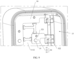
- FIG. 9 is a schematic diagram of the structure shown in FIG. 5 from another angle.
- FIG. 10 is a schematic diagram of a cross-sectional structure in direction C-C of the structure shown in FIG. 4 .
- the first guide connector 30 includes a first connecting portion 31, a second connecting portion 32, and an adapting portion 33.
- the first connecting portion 31 is fastened in the mounting groove 113 on the first surface 1111
- the second connecting portion 32 is fastened on the second surface 1112 and electrically connected to the circuit board assembly 20.
- the adapting portion 33 penetrates through the front end wall 111 and is electrically connected to each of the first connecting portion 31 and the second connecting portion 32, and the adapting portion 33 is connected to the front end wall 111 in a sealed manner to ensure airtightness of the accommodating cavity 13.
- the adapting portion 33 is fastened on the front end wall 111 through insert molding. It may be understood that, the adapting portion 33 being fastened on the front end wall 111 through insert molding, on one hand, can ensure a sealing effect between the adapting portion 33 and the front end wall 111, and on the other hand, improves manufacturing efficiency of a product by omitting a step of mounting the adapting portion 33 on the front end wall 111. Certainly, in another embodiment, the adapting portion 33 may alternatively be mounted on the front end wall 111, and a gap between the adapting portion 33 and the front end wall 111 may be sealed by using a sealing material.
- the first connecting portion 31 includes a first connecting member 311 and a first pin leaf spring 312 that are connected.
- the first connecting member 311 is electrically connected to the adapting portion 33, and the first connecting member 311 and the adapting portion 33 may be fastened by riveting.
- the first pin leaf spring 312 includes two springs that are spaced apart and electrically connected. When the first pin leaf spring 312 is electrically connected to another component, the component is fitted between the two springs, and the two springs clamp the component to implement electrical connection between the first pin leaf spring 312 and the component.
- the second connecting portion 32 includes a second connecting member 321 and a second pin leaf spring 322 that are connected.
- the second connecting member 321 is electrically connected to the adapting portion 33, and the second connecting member 321 and the adapting portion 33 may be fastened by riveting.
- the second pin leaf spring 322 is electrically connected to the circuit board assembly 20.
- a structure of the second pin leaf spring 322 may be the same as or similar to a structure of the first pin leaf spring 312.
- a connecting end, of the circuit board assembly 20, electrically connected to the second pin leaf spring 322 may be directly fitted between the two springs of the second pin leaf spring 322 to implement electrical connection between the circuit board assembly 20 and the first guide connector 30.
- the circuit board assembly 20 and the first guide connector 30 are electrically connected in a clamping manner, which is simpler, more convenient, and faster than another electrical connection manner, thereby improving manufacturing efficiency of a product.
- first connecting portion 31 and the second connecting portion 32 may not include a pin leaf spring, and the first connecting portion 31 and the second connecting portion 32 may implement electrical connection to a corresponding device in another connection manner.
- FIG. 11 is a schematic diagram of a structure of the second guide connector 40 in the structure shown in FIG. 2 .
- FIG. 12 is a schematic diagram of a structure of the second guide connector 40, shown in FIG. 11 , being fastened to the rear cover 12.
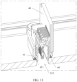
- FIG. 13 is a schematic diagram of a cross-sectional structure, in direction D-D, of the structure shown in FIG. 12 .
- the second guide connector 40 includes a first mounting member 41, a second mounting member 42, and an output terminal 43.
- One end of the output terminal 43 extends through the middle of the first mounting member 41, the other end of the output terminal 43 is electrically connected to the second mounting member 42, and the second mounting member 42 is electrically connected to the circuit board assembly 20.
- a sealing groove 411 is provided on an outer edge of the first mounting member 41, and the sealing groove 411 is disposed around the output terminal 43.
- the power adapter 100 further includes a third sealing kit 60, where the third sealing kit 60 is disposed in the sealing groove 411.
- the second guide connector 40 is fastened to the rear cover 12, the second guide connector 40 is screwed by using the screw posts 124 of the rear cover 12.
- the first mounting member 41 abuts against the plate body 121 of the rear cover 12 to compress the third sealing kit 60, and the output terminal 43 is disposed in the insertion hole 123 of the rear cover 12, so that the third sealing kit 60 seals a gap between the second guide connector 40 and a hole wall of the insertion hole 123.
- the sealing groove 411 ensures that the third sealing kit 60 is stably fastened between the first mounting member 41 and the rear cover 12.
- the second guide connector 40 is an output port of the power adapter 100, to implement electrical connection between the circuit board assembly 20 and a to-be-charged device.
- the second guide connector 40 includes one or more USB interfaces.
- the power adapter 100 is configured to charge a plurality of devices.
- the first mounting member 41 may not be provided with a sealing groove, and the third sealing kit 60 directly abuts against the first mounting member 41 and the rear cover 12.
- FIG. 14 is a schematic diagram of a cross-sectional structure, in E-E direction, of the power adapter 100 shown in FIG. 1 .
- the housing 10 further includes a front cover 14, and the front cover 14 is fastened to a side, of the housing body 11, having the front end wall 111, and covers the front end wall 111.
- the front cover 14 is provided with pins 70, and the pins 70 are made of conductive metal.
- the pins 70 penetrate through two opposite surfaces of the front cover 14 and are connected to the first guide connector 30 in a clamping manner.
- the pins 70 are input ports of the power adapter 100, and are configured to connect to an external power supply.
- the pins 70 need to be plugged and unplugged in a process of connecting to the external power supply, and a gap occurs between the pins 70 and the front cover 14 under a force during plugging and unplugging of the pins 70. If the pins 70 are directly fastened on the front end wall 111 of the housing body 11, a gap occurs between the pins 70 and the front end wall 111 during plugging and unplugging of the pins 70, and the thermally conductive liquid in the accommodating cavity 13 will leak out through the gap.
- the first guide connector 30 is provided on the front end wall 111 in this application, and the pins 70 are connected to the first guide connector 30, that is, the pins 70 are separated from the housing body 11, so that leakage of the heat conductive liquid can be avoided even if a gap occurs between the pins 70 and the front cover 14 during plugging and unplugging of the pins 70.
- the housing 10 may not include a front cover and a pin, and the first guide connector 30 is the pin 70.
- the first connecting portion 31 of the first guide connector 30 is the pin 70.
- FIG. 15 is a schematic diagram of structure of a front cover and pins according to an embodiment.
- the front cover 14 includes a cover body 141 and a connecting body 142.
- the cover body 141 includes a first surface 1411 and a second surface 1412 that are disposed oppositely, and the connecting body 142 is disposed around the periphery of the second surface 1412.
- the pin 70 is fastened to the cover body 141 of the front cover 14, penetrates through the opposite two surfaces (the first surface 1411 and the second surface 1412) of the cover body 141 of the front cover 14, and is electrically connected to the first guide connector 30. It may be understood that, one end of the pin 70 extends out of the first surface 1411 to be electrically connected to the external power supply, and the other end of the pin 70 extends out of the second surface 1412 to be electrically connected to the first guide connector 30.
- the front cover 14 may include only the cover body 141, but not include the connecting body, and the cover body 141 may be directly fastened to the front end wall 111.
- the two pins 70 are connected to respective first pin leaf springs 312 of corresponding first guide connectors 30, to implement electrical connection between the pins 70 and the circuit board assembly 20.
- the quantity of the pins 70 corresponds to the quantity of the first guide connectors 30. Positions, shapes, and sizes of the pins 70 may be flexibly set depending on a need and a related design requirement.
- the input port may alternatively be provided in another form, for example, a plug with a connecting cable.
- a stepped structure 1421 is provided on an outer surface of the connecting body 142.
- the housing body 11 also includes a connecting portion 117, and the connecting portion 117 is disposed around the edge of the front end wall 111.
- a stepped groove 1171 is provided on an inner side of the connecting portion 117, and the stepped structure 1421 of the front cover 14 is fastened in the stepped groove 1171, so that the front cover 14 and the front end wall 111 are fastened together.
- the stepped groove 1171 is configured to accommodate the front cover 14, with a position limiting effect on the front cover 14, so that the front cover 14 is stably fastened to the housing body 11.
- the stepped groove 1171 has two steps, to ensure that the front cover 14 is more stably fastened in the stepped groove 1171.
- the stepped groove 1171 may further have one step or a plurality of steps.
- the connecting portion 117 may not be provided with the stepped groove 1171, and the front cover 14 may be directly fastened on a surface, of the connecting portion 117, far away from the front end wall 111.
- the front cover 14 and the housing body 11 may be connected through ultrasonic welding.
- an adhesive may be further provided inside the stepped groove 1171, and is used to seal a gap between the stepped groove 1171 and the stepped structure 1421, to increase airtightness of the accommodating cavity 13.
- the front cover 14 and the housing body 11 may be connected in another fastening manner.
- the housing of the power adapter in this embodiment includes three parts (the front cover, the housing body, and the rear cover), and assembly of the entire machine can be realized by only two times of ultrasonic welding. In other words, an assembly process is simple and therefore manufacturing efficiency of a product is high.
- the front cover 14 covers the front end wall 111, that is, covers the sealing caps 116 and other structures, and protects the sealing caps 116 and other structures.
- surfaces that are of the sealing caps 116 and that are away from the liquid injection hole 114 or the exhaust hole 115 abut against the front cover 14.
- the cover body also has a position limiting effect on the sealing caps 116, to prevent the sealing caps 116 from loosening from the liquid injection hole 114 and the exhaust hole 115, and ensure airtightness of the accommodating cavity 13.
- the front end wall 111 further includes a groove 118, and the groove 118 is disposed, on the first surface 1111, around the liquid injection hole 114 and the exhaust hole 115.
- the groove 118 is configured to accommodate a sealing kit (not shown in the figures), and the sealing kit may be a sealing ring that is sandwiched between the groove 118 and the plate body 121 of the front cover 14. In this way, even if the thermally conductive liquid overflows from the liquid injection hole 114 and the exhaust hole 115, the overflowing thermally conductive liquid will not flow to another space between the front cover 14 and the front end wall 111.
- a first layer of sealing is implemented by using the sealing caps 116 to seal the liquid injection hole 114 and the exhaust hole 115
- a second layer of sealing is implemented by disposing the groove 118, disposing the sealing ring in the groove 118, and using the sealing ring to seal space around the liquid injection hole 114 and the exhaust hole 115.
- airtightness of the accommodating cavity 13 is improved through several layers of sealing.
- the front end wall 111 includes a sealing groove 119, and the sealing groove 119 is disposed, on the first surface 1111, around the mounting groove 113 and the groove 118.
- the power adapter 100 further includes a second sealing kit 80, and the second sealing kit 80 is disposed between the sealing groove 119 and the front cover 14. It may be understood that the sealing groove 119 is configured to accommodate and fasten the second sealing kit 80, to ensure that the second sealing kit 80 is stably fastened between the front end wall 111 and the front cover 14.
- the second sealing kit 80 Between disposing the second sealing kit 80 between the sealing groove 119 and the front cover 14, a gap between the front end wall 111 and the front cover 14 is sealed, so that even if the thermally conductive liquid overflows from the mounting groove 113 and the groove 118, the thermally conductive liquid does not overflow out of the housing 10 from the gap between the front end wall 111 and the front cover 14.
- Sealing the gap between the front end wall 111 and the front cover 14 by using the second sealing kit 80 is a third layer of sealing. In this embodiment, airtightness of the accommodating cavity 13 is improved through several layers of sealing.
- the second sealing kit 80 is a sealing ring. Certainly, in another embodiment, the second sealing kit 80 may be another sealing material.
- the front end wall 111 may include only one of the groove 118 and the sealing groove 119.
- the front end wall 111 may include neither of the groove 118 and the sealing groove 119.
- the circuit board assembly (Printed Circuit Board Assembly, PCBA) 20 includes a circuit board and electronic components (which are not shown in the figure) disposed on the circuit board.
- there is one circuit board where one end of the circuit board is inserted into the first slot 251, and the other end is inserted into the second slot 261, to fasten the circuit board assembly 20 to the housing body 11.
- the circuit board may be fixedly connected to the second guide connector 40.
- the electronic components may be, for example, various chips, transformers, or rectifier circuits, and some of the electronic components are heating electronic components.
- the power adapter 100 generates a large amount of heat during operation (in a charging state), and the heat can be quickly transferred from a high-temperature side to a low-temperature side through the thermally conductive liquid to implement even heat distribution. This improves heat dissipation efficiency of the power adapter 100, and ensures a heat dissipation effect of the power adapter 100 with a high power and a small size, so that the size of the power adapter 100 may be as small as possible when performance permits, thereby improving user experience.
Landscapes
- Engineering & Computer Science (AREA)
- Microelectronics & Electronic Packaging (AREA)
- Physics & Mathematics (AREA)
- Thermal Sciences (AREA)
- Power Engineering (AREA)
- Connector Housings Or Holding Contact Members (AREA)
Description
- This application relates to the technical field of power adapters, and in particular, to a power adapter.
- A power adapter is a power supply conversion device for portable electronic devices and electronic and electrical appliances, and is usually used for small electronic products such as a mobile phone and a notebook computer. With the progress of science and technology, users using mobile phones gradually pursue a power adapter with a higher charging speed and a smaller volume. Therefore, high power and miniaturization have become one of key selling points of power adapters in the market, and also become one of core competitiveness of brands.
- Due to increasing power and decreasing size of a mobile phone power adapter, an overall power density of the power adapter is greatly improved, and accompanying pain points are gradually obvious. For example, components inside a mobile phone power adapter with a high power generate much more heat than a conventional adapter during operation. Due to a small size, the heat is difficult to dissipate inside the power adapter, a local temperature is excessively high, and a temperature of a housing of the power adapter is then increased. Consequently, customer experience is poor in a use process. Therefore, to resolve a heat dissipation problem of a mobile phone adapter is one of key technologies.
-
US 2017/094842 A1 discloses a power supply including a casing enclosing a circuit for power conversion including one or more heat generating electronic components mounted on a circuit board, an input port configured to receive electrical energy from a power source, an output port configured to supply electrical energy to an external load, and a dielectric liquid disposed in the casing. -
US 2020/107469 A1 discloses a wireless charging device with a heat dissipation function including a case, a wireless charging assembly and a working fluid. The case includes an accommodation space. The wireless charging assembly is disposed in the accommodation space. - Embodiments of this application provide a power adapter, and the power adapter in this application has a good heat dissipation effect.
- According to a first aspect, a power adapter is provided. The power adapter includes a housing body, a rear cover, a circuit board assembly, a first guide connector, a second guide connector, and a thermally conductive liquid. The housing body has an opening, the rear cover is fastened to the housing body and covers the opening, the housing body and the rear cover are connected in a sealed manner and enclose to form an accommodating cavity, the circuit board assembly is disposed in the accommodating cavity, the thermally conductive liquid fills the accommodating cavity and wraps the circuit board assembly, the housing body includes a front end wall disposed opposite to the rear cover, the first guide connector is mounted on the front end wall and connected to the front end wall in a sealed manner, the second guide connector is mounted on the rear cover and is connected to the rear cover in a sealed manner, and both the first guide connector and the second guide connector are electrically connected to the circuit board assembly.
- It may be understood that if two components are connected in a sealed manner, it indicates that there is no gap between the two components after the two components are connected.
- It should be noted that when the power adapter is in operation, the circuit board assembly generates heat. A related technology implements even heat distribution in the following three manners. In a first manner, heat generated by the circuit board assembly is dissipated from a high-temperature area to a low-temperature area through air inside the power adapter, so that an even heat distribution effect is achieved inside the power adapter. However, in such manner, a heat dissipation speed is low, and a local temperature is excessively high. Therefore, high-temperature overload protection of components of the circuit board assembly is caused and the components stop operating. In a second manner, a potting adhesive is injected into the power adapter, and is used in place of air as a medium for transferring heat, so that an even heat distribution effect is achieved inside the power adapter. However, the injected potting adhesive will affect electromagnetic compatibility of the components of the circuit board assembly. In a third manner, a thermally conductive white adhesive is applied around the components generating a high temperature of the circuit board assembly, to achieve fastening and thermal conduction effects, increase a heat dissipation area, and transfer heat, so that the components achieve an even heat distribution effect. However, a curing time of the white adhesive is long, and it is difficult to control a dispensing range and easy to pollute the components.
- In view of this, in this application, the housing body and the rear cover enclose to form the accommodating cavity, the housing body and the rear cover are connected in a sealed manner, the thermally conductive liquid can fill the accommodating cavity and wrap the circuit board assembly, and both the first guide connector and the second guide connector are connected to the housing in a sealed manner to ensure that the thermally conductive liquid does not leak. In this way, heat emitted by the circuit board assembly during operation may be quickly transferred from a high-temperature side to a low-temperature side through the thermally conductive liquid to implement even heat distribution, thereby improving heat dissipation efficiency of the power adapter. Compared with the manner of injecting an adhesive into the power adapter or the manner of applying the thermally conductive white adhesive around the components generating a high temperature, this application does not affect electric performance of the circuit board assembly, ensuring a heat dissipation effect of the power adapter with a high power and a small size. Therefore, the size of the power adapter may be as small as possible when performance permits, thereby improving user experience.
- In a possible implementation, the first guide connector includes a first connecting portion, a second connecting portion, and an adapting portion, the front end wall includes a first surface and a second surface disposed opposite to each other, the second surface faces toward the accommodating cavity, the first connecting portion is fastened on the first surface, the second connecting portion is fastened on the second surface and electrically connected to the circuit board assembly, the adapting portion penetrates through the front end wall and is electrically connected to each of the first connecting portion and the second connecting portion, and the adapting portion is connected to the front end wall in a sealed manner to ensure airtightness of the accommodating cavity.
- In a possible implementation not covered by the claimed invention, the adapting portion is fastened on the front end wall through insert molding. It may be understood that, the adapting portion being fastened on the front end wall through insert molding, on one hand, can ensure a sealing effect between the adapting portion and the front end wall, and on the other hand, improves manufacturing efficiency of a product by omitting a step of mounting the adapting portion on the front end wall. Certainly, in another embodiment, the adapting portion may alternatively be mounted on the front end wall, and a gap between the adapting portion and the front end wall may be sealed by using a sealing material.
- In a possible implementation, the first connecting portion is a pin.
- In a possible implementation, the power adapter further includes a front cover, pins are provided on the front cover, the pins penetrate through two opposite surfaces of the front cover, the front cover is fastened on the front end wall, and the pins are connected to the first guide connector. It may be understood that the pins need to be plugged and unplugged in a process of connecting to the external power supply, and a gap occurs between the pins and the front cover under a force during plugging and unplugging of the pins. If the pins are directly fastened on the front end wall of the housing body, a gap occurs between the pins and the front end wall during plugging and unplugging of the pins, and the thermally conductive liquid in the accommodating cavity will leak out through the gap. To avoid leakage of the thermally conductive liquid, the first guide connector is provided on the front end wall in this application, and the pins are connected to the first guide connector, that is, the pins are separated from the housing body, so that leakage of the thermally conductive liquid can be avoided even if a gap occurs between the pins and the front cover during plugging and unplugging of the pins.
- In a possible implementation, the front end wall includes a sealing groove, and the sealing groove is disposed around the first guide connector. The power adapter further includes a second sealing kit, and the second sealing kit is disposed between the sealing groove and the front cover. It may be understood that the sealing groove is configured to accommodate and fasten the second sealing kit, to ensure that the second sealing kit is stably fastened between the front end wall and the front cover. The second sealing kit is disposed between the sealing groove and the front cover to seal a gap between the front end wall and the front cover. In this embodiment, airtightness of the accommodating cavity is improved through several layers of sealing.
- The front end wall is provided with a liquid injection hole, through which the thermally conductive liquid is filled into the accommodating cavity. In this embodiment, the liquid injection hole is provided in the front end wall, so that during assembly of the power adapter, the circuit board assembly may be fastened inside the housing body, then the rear cover is fastened to the housing body and sealed with the housing body, and finally, the thermally conductive liquid is filled into the accommodating cavity through the liquid injection hole. Compared with a manner of filling the thermally conductive liquid into the accommodating cavity before the rear cover is fastened to the housing body, the operation in this embodiment is more convenient, and the thermally conductive liquid can be more fully filled into the accommodating cavity, thereby achieving a better heat dissipation effect.
- In a possible implementation, the power adapter further includes a sealing cap, and the sealing cap is fastened to the liquid injection hole, to prevent the thermally conductive liquid filled into the accommodating cavity from overflowing from the liquid injection hole, thereby ensuring airtightness of the accommodating cavity.
- In a possible implementation, the power adapter further includes a front cover, and the front cover is fastened on the front end wall. A surface that is of the sealing cap and that faces away from the liquid injection hole abuts against the front cover. In other words, the cover body also has a position limiting effect on the sealing cap, to prevent the sealing cap from loosening from the liquid injection hole and an exhaust hole and ensure airtightness of the accommodating cavity.
- The power adapter further includes an exhaust hole, and the exhaust hole is provided in the front end wall and is connected to the accommodating cavity. According to this embodiment, the exhaust hole is provided, so that when the thermally conductive liquid is filled through the liquid injection hole into the accommodating cavity, air in the accommodating cavity may be discharged from the exhaust hole in time. In this way, a speed of filling the thermally conductive liquid into the accommodating cavity is not hindered, efficient filling of the thermally conductive liquid is implemented, and manufacturing efficiency of a product is improved.
- In a possible implementation, the power adapter further includes a third sealing kit, the rear cover is provided with an insertion hole, the second guide connector is fastened to the insertion hole, and the second guide connector and a hole wall of the insertion hole are sealed by using the third sealing kit, to prevent the thermally conductive liquid in the accommodating cavity from leaking out from a gap between the second guide connector and the insertion hole, thereby ensuring airtightness of the accommodating cavity.
- To describe technical solutions in embodiments of this application or in the background more clearly, the following describes the accompanying drawings for describing embodiments of this application or the background.
-
FIG. 1 is a schematic diagram of a structure of a power adapter according to an embodiment of this application; -
FIG. 2 is a schematic exploded diagram of a power adapter shown inFIG. 1 ; -
FIG. 3 is a schematic diagram of a cross-sectional structure, in A-A direction, of a power adapter shown inFIG. 1 ; -
FIG. 4 is a schematic diagram of a structure of a housing body and a first guide connector in the structure shown inFIG. 2 ; -
FIG. 5 is a schematic diagram of the structure shown inFIG. 4 from another angle; -
FIG. 6 is a diagram of a cross-sectional structure, in direction B-B, of the structure shown inFIG. 1 ; -
FIG. 7 is a schematic diagram of a structure of a rear cover in the structure shown inFIG. 2 ; -
FIG. 8 is a locally enlarged schematic diagram of the structure shown inFIG. 4 ; -
FIG. 9 is a schematic diagram of the structure shown inFIG. 5 from another angle; -
FIG. 10 is a schematic diagram of a cross-sectional structure, in direction C-C, of the structure shown inFIG. 4 ; -
FIG. 11 is a schematic diagram of a structure of a second guide connector in the structure shown inFIG. 2 ; -
FIG. 12 is a schematic diagram of a structure of a second guide connector, shown inFIG. 11 , being fastened to a rear cover; -
FIG. 13 is a schematic diagram of a cross-sectional structure, in direction D-D, of the structure shown inFIG. 12 ; -
FIG. 14 is a schematic diagram of a cross-sectional structure, in E-E direction, of a power adapter shown inFIG. 1 ; and -
FIG. 15 is a schematic diagram of structure of a front cover and pins according to an embodiment. - The following describes embodiments of this application with reference to the accompanying drawings in embodiments of this application.
- In descriptions of the embodiments of this application, it should be noted that, unless otherwise clearly specified and limited, terms "mounting" and "connection" should be understood in a broad sense. For example, "connection" may a detachable connection or a non-detachable connection, or may be a direct connection or an indirect connection via an intermediate medium. "Fixed connection" refers to mutual connection and relative positions remain unchanged after the connection. Orientation terms mentioned in the embodiments of this application, such as, "front", "rear", "inside", and "outside", are merely orientations with reference to the accompanying drawings. Therefore, the orientation terms are used to better and more clearly describe and understand the embodiments of this application, rather than to indicate or imply that an apparatus or a component needs to have a specific orientation, or be constructed and operated in a specific orientation. Therefore, these orientation terms cannot be construed as a limitation on the embodiments of this application. "A plurality of" means at least two.
- It may be understood that specific embodiments described herein are merely intended to explain related embodiments, rather than to limit the embodiments. It should be further noted that, for convenience of description, only parts related to the embodiments are shown in the accompanying drawings.
-
FIG. 1 is a schematic diagram of a structure of apower adapter 100 according to an embodiment of this application. - An embodiment of this application provides a
power adapter 100. Thepower adapter 100 may be an adapter for various electronic devices and electronic and electrical appliances, may be a consumer electronic product, or may be another device for a server or a data center. Specifically, thepower adapter 100 includes but is not limited to a mobile phone power adapter, an iPad power adapter, a power adapter for a notebook/gaming laptop, a car charger, or the like. Thepower adapter 100 being a mobile phone power adapter is used as an example inFIG. 1 for specific description. - Refer to
FIG. 1 ,FIG. 2 , andFIG. 3 .FIG. 2 is a schematic exploded diagram of thepower adapter 100 shown inFIG. 1 .FIG. 3 is a schematic diagram of a cross-sectional structure, in A-A direction, of thepower adapter 100 shown inFIG. 1 . - The
power adapter 100 may include ahousing 10, acircuit board assembly 20, afirst guide connector 30, asecond guide connector 40, afirst sealing kit 50, and a thermally conductive liquid (which is not shown in the figure). Thehousing 10 may include ahousing body 11 and arear cover 12, where thehousing body 11 has anopening 110, therear cover 12 is fastened to thehousing body 11 and covers theopening 110, thehousing body 11 and therear cover 12 are connected in a sealed manner and enclose to form anaccommodating cavity 13, thecircuit board assembly 20 is provided in theaccommodating cavity 13, the thermally conductive liquid fills theaccommodating cavity 13 and wraps thecircuit board assembly 20, thehousing body 11 includes afront end wall 111 disposed opposite to therear cover 12, thefirst guide connector 30 is mounted on thefront end wall 111 and is connected to thefront end wall 111 in a sealed manner, thesecond guide connector 40 is mounted on therear cover 12 and is connected to therear cover 12 in a sealed manner, and both thefirst guide connector 30 and thesecond guide connector 40 are electrically connected to thecircuit board assembly 20. - It may be understood that if two components are connected in a sealed manner, it indicates that there is no gap between the two components after the two components are connected.
- It should be noted that when the
power adapter 100 is in operation, thecircuit board assembly 20 generates heat. A related technology implements even heat distribution in the following three manners. In a first manner, heat generated by the circuit board assembly is dissipated from a high-temperature area to a low-temperature area through air inside the power adapter, so that an even heat distribution effect is achieved inside the power adapter. However, in such manner, a heat dissipation speed is low, and a local temperature is excessively high. Therefore, high-temperature overload protection of components of the circuit board assembly is caused and the components stop operating. In a second manner, a potting adhesive is injected into the power adapter, and is used in place of air as a medium for transferring heat, so that an even heat distribution effect is achieved inside the power adapter. However, the injected potting adhesive will affect electromagnetic compatibility of the components of the circuit board assembly. In a third manner, a thermally conductive white adhesive is applied around the components generating a high temperature, of the circuit board assembly, to achieve fastening and thermal conduction effects, increase a heat dissipation area, and transfer heat, so that the components achieve an even heat distribution effect. However, a curing time of the white adhesive is long, it is difficult to control a dispensing range, and the components are easily polluted. - In view of this, in this application, the
housing body 11 and therear cover 12 enclose to form theaccommodating cavity 13, thehousing body 11 and therear cover 12 are connected in a sealed manner, the thermally conductive liquid can fill theaccommodating cavity 13 and wrap thecircuit board assembly 20, and both thefirst guide connector 30 and thesecond guide connector 40 are connected to thehousing 10 in a sealed manner to ensure that the thermally conductive liquid does not leak. In this way, heat emitted by thecircuit board assembly 20 during operation may be quickly transferred from a high-temperature side to a low-temperature side through the thermally conductive liquid to implement even heat distribution, thereby improving heat dissipation efficiency of thepower adapter 100. Compared with the manner of injecting an adhesive into the power adapter or the manner of applying the thermally conductive white adhesive around the components generating a high temperature, this application does not affect electric performance of thecircuit board assembly 20, ensuring a heat dissipation effect of thepower adapter 100 with a high power and a small size. Therefore, the size of thepower adapter 100 may be as small as possible when performance permits, thereby improving user experience. - In this embodiment, the thermally conductive liquid is an insulation liquid with a strong heat absorption capability, and presents an excellent thermally conductive effect without affecting electrical performance of the
circuit board assembly 20, so that a heat dissipation effect of thepower adapter 100 is improved. The thermally conductive liquid may be an oil liquid, for example, lubricating oil for a speed reducer. - In this embodiment, the
power adapter 100 includes afirst sealing kit 50, where thefirst sealing kit 50 is disposed between therear cover 12 and thehousing body 11 to seal theaccommodating cavity 13, that is, thehousing body 11 and therear cover 12 are connected in a sealed manner by thefirst sealing kit 50. In another embodiment, another material may be used for sealed connection between thehousing body 11 and therear cover 12. - In this embodiment, the
housing body 11 and therear cover 12 may be connected through ultrasonic welding. Thefirst sealing kit 50 is compressed during ultrasonic welding for connection between thehousing body 11 and therear cover 12, so that thefirst sealing kit 50 fills a gap between thehousing body 11 and therear cover 12, thereby effectively improving airtightness of theaccommodating cavity 13. Certainly, in another embodiment, thehousing body 11 and therear cover 12 may be connected in another manner. This is not limited in this application. - In this embodiment, the
first sealing kit 50 may be a sealing ring. It may be understood that it is easier to fit a sealing ring between thehousing body 11 and therear cover 12 than another sealing material. Certainly, in another embodiment, thefirst sealing kit 50 may be another sealing material such as a sealing adhesive. - Refer to
FIG. 3 andFIG. 4. FIG. 4 is a schematic diagram of a structure of thehousing body 11 and thefirst guide connector 30 in the structure shown inFIG. 2 . - In this embodiment, the
housing body 11 is cuboid. Thehousing body 11 further includes aperipheral side wall 112 connected to and disposed around the periphery of thefront end wall 111, and anopening 110 is provided on a side that is of theperipheral side wall 112 and that faces away from thefront end wall 111. One end that is of theperipheral side wall 112 and that is far away from thefront end wall 111 is fastened to therear cover 12. Thefront end wall 111, theperipheral side wall 112, and therear cover 12 jointly enclose to form theaccommodating cavity 13. Certainly, in another embodiment, thehousing body 11 may alternatively be cylindrical, cubic, or the like. - The
front end wall 111 includes afirst surface 1111 and asecond surface 1112 disposed opposite to each other, where thefirst surface 1111 faces away from theaccommodating cavity 13, and thesecond surface 1112 faces toward theaccommodating cavity 13. Thefirst surface 1111 is provided with a mountinggroove 113, and thefirst guide connector 30 is mounted in the mountinggroove 113. It may be understood that when thefirst guide connector 30 is mounted in the mountinggroove 113, thefirst guide connector 30 and thefront end wall 111 have overlapping portions in a thickness direction of thefront end wall 111. Such manner can miniaturize thepower adapter 100 in the thickness direction of thefront end wall 111 compared with a manner of directly mounting thefirst guide connector 30 on thefirst surface 1111. Certainly, in another embodiment, thefirst surface 1111 may not be provided with a mounting groove, and thefirst guide connector 30 may be directly mounted on thefirst surface 1111. - In this embodiment, the
front end wall 111 is provided with aliquid injection hole 114, where theliquid injection hole 114 penetrates through thefront end wall 111 and is connected to theaccommodating cavity 13, and theliquid injection hole 114 and the mountinggroove 113 are spaced apart. The thermally conductive liquid is filled into theaccommodating cavity 13 through theliquid injection hole 114. In this embodiment, theliquid injection hole 114 is provided in thefront end wall 111, so that during assembly of thepower adapter 100, thecircuit board assembly 20 may be fastened inside thehousing body 11, then therear cover 12 is fastened to thehousing body 11 and sealed with thehousing body 11, and finally, the thermally conductive liquid is filled into theaccommodating cavity 13 through theliquid injection hole 114. Compared with a manner of filling the thermally conductive liquid into theaccommodating cavity 13 before therear cover 12 is fastened to thehousing body 11, the operation in this embodiment is more convenient, and the thermally conductive liquid can be more fully filled into theaccommodating cavity 13, thereby achieving a better heat dissipation effect. Certainly, in another scenario not covered by the invention, thefront end wall 111 may not be provided with a liquid injection hole, and the thermally conductive liquid is filled into theaccommodating cavity 13 before therear cover 12 is fastened to thehousing body 11. - For example, there is one
liquid injection hole 114 in this embodiment, and theliquid injection hole 114 is circular. Certainly, in another embodiment, there may be a plurality of liquid injection holes 114, which may be in a same shape or in different shapes. Theliquid injection hole 114 may be circular, star-shaped, square, or irregular in shape. - In this embodiment, the
power adapter 100 further includes anexhaust hole 115, and theexhaust hole 115 is provided formed in thefront end wall 111 and is connected to theaccommodating cavity 13. Theexhaust hole 115 is provided adjacent to theliquid injection hole 114. According to this embodiment, theexhaust hole 115 is provided, so that when the thermally conductive liquid is filled through theliquid injection hole 114 into theaccommodating cavity 13, air in theaccommodating cavity 13 may be discharged from theexhaust hole 115 in time. In this way, a speed of filling the thermally conductive liquid into theaccommodating cavity 13 is not hindered, efficient filling of the thermally conductive liquid is implemented, and manufacturing efficiency of a product is improved. In this embodiment, theexhaust hole 115 and theliquid injection hole 114 have a same diameter, to ensure efficient filling of the thermally conductive liquid. - Certainly, in an implementation scenario not covered by the invention, the
power adapter 100 may not include an exhaust hole. In another implementation scenario of another embodiment, theexhaust hole 115 may alternatively be disposed at the edge of theliquid injection hole 114 and is connected to theliquid injection hole 114. In still another implementation scenario of another embodiment, theexhaust hole 115 and theliquid injection hole 114 may have different diameters. - For example, there is one
exhaust hole 115 in this embodiment, and theexhaust hole 115 is circular. Certainly, in another embodiment, there may be a plurality ofexhaust holes 115, which may be in a same shape or in different shapes. Theexhaust hole 115 may be circular, star-shaped, square, or irregular in shape. - Refer to
FIG. 2 andFIG. 4 . In this embodiment, thepower adapter 100 further includes sealingcaps 116 for respectively sealing theliquid injection hole 114 and theexhaust hole 115. Specifically, there are two sealingcaps 116, one of which is fastened to theliquid injection hole 114 to seal theliquid injection hole 114, and the other one is fastened to theexhaust hole 115 to seal theexhaust hole 115. This prevents the thermally conductive liquid filled into theaccommodating cavity 13 from overflowing from theliquid injection hole 114 and theexhaust hole 115, and ensures airtightness of theaccommodating cavity 13. - Certainly, in an implementation scenario of another embodiment, a quantity of sealing
caps 116 is not limited to two, and the quantity of sealingcaps 116 corresponds to a total quantity ofexhaust holes 115 and liquid injection holes 114. In another implementation scenario of another embodiment, thepower adapter 100 may not include a sealing cap, and a sealing material may be used to seal theliquid injection hole 114 and theexhaust hole 115 after the thermally conductive liquid is filled into theaccommodating cavity 13. In still another implementation scenario of another embodiment, thefirst surface 1111 may further be provided with a fixed structure to limit positions of the sealing caps 116, to prevent the sealing caps 116 from loosening from theliquid injection hole 114 or theexhaust hole 115. - Refer to
FIG. 3 andFIG. 5. FIG. 5 is a schematic diagram of the structure shown inFIG. 4 from another angle. - In this embodiment, the
peripheral side wall 112 includes an end portion that is far away from thefront end wall 111, and an outer side of the end portion is provided with afitting groove 1121, where thefitting groove 1121 is configured to fit therear cover 12. On the one hand, thefitting groove 1121 is configured to accommodate a portion that is of therear cover 12 and that is connected to theperipheral side wall 112, to perform a position limiting effect on therear cover 12, so that therear cover 12 is stably fastened to theperipheral side wall 112. On the other hand, when therear cover 12 is mounted on theperipheral side wall 112, thefitting groove 1121 facilitates quick matching between therear cover 12 and theperipheral side wall 112, so that therear cover 12 is quickly mounted on theperipheral side wall 112. Certainly, in another embodiment, the outer side of the end portion may not be provided with a fitting groove, and the end portion is directly fixedly connected to therear cover 12. - An inner side of the end portion is provided with an abutting
groove 1122, and the abuttinggroove 1122 is configured to accommodate thefirst sealing kit 50 in cooperation with therear cover 12, to make thefirst sealing kit 50 be located between the abuttinggroove 1122 and therear cover 12 and stably located between theperipheral side wall 112 and therear cover 12, thereby ensuring airtightness of theaccommodating cavity 13. Certainly, in another embodiment, the inner side of the end portion may not be provided with an abutting groove, and thefirst sealing kit 50 may be directly fastened between the end portion and therear cover 12. - Refer to
FIG. 4 andFIG. 6. FIG. 6 is a diagram of a cross-sectional structure, in direction B-B, of the structure shown inFIG. 1 . - The
peripheral side wall 112 includes afirst side wall 1123 and asecond side wall 1124 disposed oppositely. Afirst fastening portion 1125 and asecond fastening portion 1126 are respectively provided on surfaces, of thefirst side wall 1123 and thesecond side wall 1124, facing toward theaccommodating cavity 13. Thefirst fastening portion 1125 and thesecond fastening portion 1126 are disposed oppositely. One end of thecircuit board assembly 20 is fastened to thefirst fastening portion 1125, and the other end is fastened to thesecond fastening portion 1126, to stably fasten thecircuit board assembly 20 inside thehousing body 11. Certainly, in another embodiment, thecircuit board assembly 20 may alternatively be directly fastened on theperipheral side wall 112. - In this embodiment, the
first fastening portion 1125 is provided with afirst slot 251, and thesecond fastening portion 1126 is provided with asecond slot 261, so that one end of thecircuit board assembly 20 may be inserted into thefirst slot 251, and the other end may be inserted into thesecond slot 261. In this way, thecircuit board assembly 20 can be securely fastened inside thehousing body 11, and an overall strength of thepower adapter 100 can be increased. In addition, compared with other fastening manners, the manner of fastening thecircuit board assembly 20 by inserting thecircuit board assembly 20 into the slots is simpler and easy for assembly, thereby effectively improving manufacturing efficiency. - Certainly, in an implementation scenario of another embodiment, the
first side wall 1123 and thesecond side wall 1124 may not be provided with fastening portions, and thefirst slot 251 and thesecond slot 261 may be respectively provided on thefirst side wall 1123 and thesecond side wall 1124. Such arrangement facilitates miniaturization of thepower adapter 100. In another implementation scenario of another embodiment, thecircuit board assembly 20 may be fastened inside thehousing body 11 in another manner. This is not limited in this application. - Refer to
FIG. 2 andFIG. 7. FIG. 7 is a schematic diagram of a structure of therear cover 12 in the structure shown inFIG. 2 . - The
rear cover 12 may include aplate body 121 and a connectingportion 122. Theplate body 121 includes afirst surface 1211 and asecond surface 1212 that are disposed oppositely, and the connectingportion 122 is disposed around the periphery of thesecond surface 1212. The connectingportion 122 is configured to fit thehousing body 11, to implement a fixed connection between therear cover 12 and thehousing body 11. Certainly, in another embodiment, therear cover 12 may include only theplate body 121, but not include the connecting portion, and theplate body 121 may be directly fastened to thehousing body 11. - The
rear cover 12 is provided with aninsertion hole 123, theinsertion hole 123 penetrates through two opposite surfaces of theplate body 121, and thesecond guide connector 40 is fastened to theinsertion hole 123. Thesecond surface 1112 is further provided with twoscrew posts 124, where the twoscrew posts 124 are respectively provided on two opposite sides of theinsertion hole 123. The screw posts 124 are configured to fit thesecond guide connector 40 so that thesecond guide connector 40 is fastened to theinsertion hole 123. Certainly, in another embodiment, a quantity ofscrew posts 124 may be any quantity other than two. Thesecond surface 1112 may not be provided with a screw post, and thesecond guide connector 40 may be fastened to theinsertion hole 123 by using another fastening structure. - In this embodiment, as shown in
FIG. 3 andFIG. 7 , afirst groove 1221 and asecond groove 1222 are provided at spacings on a surface that is of the connectingportion 122 and that is far away from theplate body 121, where thefirst groove 1221 is disposed around the middle of theplate body 121, and thesecond groove 1222 is disposed around thefirst groove 1221. Thefirst groove 1221 is configured to accommodate thefirst sealing kit 50, so that a position of one end of thefirst sealing kit 50 is limited to thefirst groove 1221, and a position of the other end is limited to the abuttinggroove 1122 of theperipheral side wall 112. Thefirst groove 1221 and the abuttinggroove 1122 jointly fasten thefirst sealing kit 50, so that thefirst sealing kit 50 is stably fastened between thehousing body 11 and therear cover 12, thereby ensuring airtightness of theaccommodating cavity 13. Thesecond groove 1222 is configured to fit the end portion of theperipheral side wall 112, and the end portion of theperipheral side wall 112 is accommodated in thesecond groove 1222, thereby ensuring stability of connection between thehousing body 11 and therear cover 12. Certainly, in another embodiment, the connectingportion 122 may not be provided with thefirst groove 1221 and/or thesecond groove 1222. - In some embodiments, an adhesive is further applied between the
second groove 1222 and an edge wall of theperipheral side wall 112, and the adhesive is used to seal a gap between thesecond groove 1222 and theperipheral side wall 112, to increase airtightness of theaccommodating cavity 13. It may be understood that, during fastening therear cover 12 to thehousing body 11, thefirst sealing kit 50 may be first mounted in thefirst groove 1221, then the adhesive is applied inside thesecond groove 1222, and therear cover 12 is mounted on theperipheral side wall 112 and is fastened to theperipheral side wall 112 through ultrasonic welding. It may be understood that, in this embodiment, a first layer of sealing is implemented between therear cover 12 and thehousing body 11 by using thefirst sealing kit 50, and a second layer of sealing is implemented by applying an adhesive in thesecond groove 1222, so that airtightness between therear cover 12 and thehousing body 11 is enhanced through several layers of sealing. - Refer to
FIG. 8 ,FIG. 9 , andFIG. 10 .FIG. 8 is a locally enlarged schematic diagram of the structure shown inFIG. 4 .FIG. 9 is a schematic diagram of the structure shown inFIG. 5 from another angle.FIG. 10 is a schematic diagram of a cross-sectional structure in direction C-C of the structure shown inFIG. 4 . - The
first guide connector 30 includes a first connectingportion 31, a second connectingportion 32, and an adaptingportion 33. The first connectingportion 31 is fastened in the mountinggroove 113 on thefirst surface 1111, and the second connectingportion 32 is fastened on thesecond surface 1112 and electrically connected to thecircuit board assembly 20. The adaptingportion 33 penetrates through thefront end wall 111 and is electrically connected to each of the first connectingportion 31 and the second connectingportion 32, and the adaptingportion 33 is connected to thefront end wall 111 in a sealed manner to ensure airtightness of theaccommodating cavity 13. In this embodiment, there are twofirst guide connectors 30, and the twofirst guide connectors 30 are spaced apart. Certainly, in another embodiment, there may be one or morefirst guide connectors 30. - In this embodiment, the adapting
portion 33 is fastened on thefront end wall 111 through insert molding. It may be understood that, the adaptingportion 33 being fastened on thefront end wall 111 through insert molding, on one hand, can ensure a sealing effect between the adaptingportion 33 and thefront end wall 111, and on the other hand, improves manufacturing efficiency of a product by omitting a step of mounting the adaptingportion 33 on thefront end wall 111. Certainly, in another embodiment, the adaptingportion 33 may alternatively be mounted on thefront end wall 111, and a gap between the adaptingportion 33 and thefront end wall 111 may be sealed by using a sealing material. - In this embodiment, the first connecting
portion 31 includes a first connectingmember 311 and a firstpin leaf spring 312 that are connected. The first connectingmember 311 is electrically connected to the adaptingportion 33, and the first connectingmember 311 and the adaptingportion 33 may be fastened by riveting. The firstpin leaf spring 312 includes two springs that are spaced apart and electrically connected. When the firstpin leaf spring 312 is electrically connected to another component, the component is fitted between the two springs, and the two springs clamp the component to implement electrical connection between the firstpin leaf spring 312 and the component. - The second connecting
portion 32 includes a second connectingmember 321 and a secondpin leaf spring 322 that are connected. The second connectingmember 321 is electrically connected to the adaptingportion 33, and the second connectingmember 321 and the adaptingportion 33 may be fastened by riveting. The secondpin leaf spring 322 is electrically connected to thecircuit board assembly 20. A structure of the secondpin leaf spring 322 may be the same as or similar to a structure of the firstpin leaf spring 312. A connecting end, of thecircuit board assembly 20, electrically connected to the secondpin leaf spring 322 may be directly fitted between the two springs of the secondpin leaf spring 322 to implement electrical connection between thecircuit board assembly 20 and thefirst guide connector 30. Thecircuit board assembly 20 and thefirst guide connector 30 are electrically connected in a clamping manner, which is simpler, more convenient, and faster than another electrical connection manner, thereby improving manufacturing efficiency of a product. - Certainly, in another embodiment, the first connecting
portion 31 and the second connectingportion 32 may not include a pin leaf spring, and the first connectingportion 31 and the second connectingportion 32 may implement electrical connection to a corresponding device in another connection manner. - Refer to
FIG. 11 ,FIG. 12 , andFIG. 13 .FIG. 11 is a schematic diagram of a structure of thesecond guide connector 40 in the structure shown inFIG. 2 .FIG. 12 is a schematic diagram of a structure of thesecond guide connector 40, shown inFIG. 11 , being fastened to therear cover 12.FIG. 13 is a schematic diagram of a cross-sectional structure, in direction D-D, of the structure shown inFIG. 12 . - In this embodiment, the
second guide connector 40 includes a first mountingmember 41, a second mountingmember 42, and anoutput terminal 43. One end of theoutput terminal 43 extends through the middle of the first mountingmember 41, the other end of theoutput terminal 43 is electrically connected to the second mountingmember 42, and the second mountingmember 42 is electrically connected to thecircuit board assembly 20. - A sealing groove 411 is provided on an outer edge of the first mounting
member 41, and the sealing groove 411 is disposed around theoutput terminal 43. Thepower adapter 100 further includes athird sealing kit 60, where thethird sealing kit 60 is disposed in the sealing groove 411. When thesecond guide connector 40 is fastened to therear cover 12, thesecond guide connector 40 is screwed by using the screw posts 124 of therear cover 12. The first mountingmember 41 abuts against theplate body 121 of therear cover 12 to compress thethird sealing kit 60, and theoutput terminal 43 is disposed in theinsertion hole 123 of therear cover 12, so that thethird sealing kit 60 seals a gap between thesecond guide connector 40 and a hole wall of theinsertion hole 123. This prevents the thermally conductive liquid in theaccommodating cavity 13 from leaking out through the gap between thesecond guide connector 40 and theinsertion hole 123, and ensures airtightness of theaccommodating cavity 13. In addition, the sealing groove 411 ensures that thethird sealing kit 60 is stably fastened between the first mountingmember 41 and therear cover 12. - It may be understood that the
second guide connector 40 is an output port of thepower adapter 100, to implement electrical connection between thecircuit board assembly 20 and a to-be-charged device. Thesecond guide connector 40 includes one or more USB interfaces. In some implementations, thepower adapter 100 is configured to charge a plurality of devices. - Certainly, in another embodiment, the first mounting
member 41 may not be provided with a sealing groove, and thethird sealing kit 60 directly abuts against the first mountingmember 41 and therear cover 12. - Refer to
FIG. 2 andFIG. 14 again.FIG. 14 is a schematic diagram of a cross-sectional structure, in E-E direction, of thepower adapter 100 shown inFIG. 1 . - The
housing 10 further includes afront cover 14, and thefront cover 14 is fastened to a side, of thehousing body 11, having thefront end wall 111, and covers thefront end wall 111. Thefront cover 14 is provided withpins 70, and thepins 70 are made of conductive metal. Thepins 70 penetrate through two opposite surfaces of thefront cover 14 and are connected to thefirst guide connector 30 in a clamping manner. Thepins 70 are input ports of thepower adapter 100, and are configured to connect to an external power supply. - It may be understood that the
pins 70 need to be plugged and unplugged in a process of connecting to the external power supply, and a gap occurs between thepins 70 and thefront cover 14 under a force during plugging and unplugging of thepins 70. If thepins 70 are directly fastened on thefront end wall 111 of thehousing body 11, a gap occurs between thepins 70 and thefront end wall 111 during plugging and unplugging of thepins 70, and the thermally conductive liquid in theaccommodating cavity 13 will leak out through the gap. To avoid leakage of the thermally conductive liquid, thefirst guide connector 30 is provided on thefront end wall 111 in this application, and thepins 70 are connected to thefirst guide connector 30, that is, thepins 70 are separated from thehousing body 11, so that leakage of the heat conductive liquid can be avoided even if a gap occurs between thepins 70 and thefront cover 14 during plugging and unplugging of thepins 70. - Certainly, in a scenario of another embodiment, the
housing 10 may not include a front cover and a pin, and thefirst guide connector 30 is thepin 70. Alternatively, the first connectingportion 31 of thefirst guide connector 30 is thepin 70. - Refer to
FIG. 14 andFIG. 15. FIG. 15 is a schematic diagram of structure of a front cover and pins according to an embodiment. - The
front cover 14 includes acover body 141 and a connectingbody 142. Thecover body 141 includes a first surface 1411 and asecond surface 1412 that are disposed oppositely, and the connectingbody 142 is disposed around the periphery of thesecond surface 1412. Thepin 70 is fastened to thecover body 141 of thefront cover 14, penetrates through the opposite two surfaces (the first surface 1411 and the second surface 1412) of thecover body 141 of thefront cover 14, and is electrically connected to thefirst guide connector 30. It may be understood that, one end of thepin 70 extends out of the first surface 1411 to be electrically connected to the external power supply, and the other end of thepin 70 extends out of thesecond surface 1412 to be electrically connected to thefirst guide connector 30. Certainly, in another embodiment, thefront cover 14 may include only thecover body 141, but not include the connecting body, and thecover body 141 may be directly fastened to thefront end wall 111. - In this embodiment, there are two
pins 70, and the twopins 70 are connected to respective firstpin leaf springs 312 of correspondingfirst guide connectors 30, to implement electrical connection between thepins 70 and thecircuit board assembly 20. Certainly, in another embodiment, there may be another quantity ofpins 70. Specifically, the quantity of thepins 70 corresponds to the quantity of thefirst guide connectors 30. Positions, shapes, and sizes of thepins 70 may be flexibly set depending on a need and a related design requirement. In another implementation, the input port may alternatively be provided in another form, for example, a plug with a connecting cable. - As shown in
FIG. 4 ,FIG. 14 , andFIG. 15 , in this embodiment, a steppedstructure 1421 is provided on an outer surface of the connectingbody 142. Thehousing body 11 also includes a connectingportion 117, and the connectingportion 117 is disposed around the edge of thefront end wall 111. A steppedgroove 1171 is provided on an inner side of the connectingportion 117, and the steppedstructure 1421 of thefront cover 14 is fastened in the steppedgroove 1171, so that thefront cover 14 and thefront end wall 111 are fastened together. In this embodiment, the steppedgroove 1171 is configured to accommodate thefront cover 14, with a position limiting effect on thefront cover 14, so that thefront cover 14 is stably fastened to thehousing body 11. - In this embodiment, the stepped
groove 1171 has two steps, to ensure that thefront cover 14 is more stably fastened in the steppedgroove 1171. Certainly, in an implementation scenario of another embodiment, the steppedgroove 1171 may further have one step or a plurality of steps. In another implementation scenario of the another embodiment, the connectingportion 117 may not be provided with the steppedgroove 1171, and thefront cover 14 may be directly fastened on a surface, of the connectingportion 117, far away from thefront end wall 111. - The
front cover 14 and thehousing body 11 may be connected through ultrasonic welding. In some implementations, an adhesive may be further provided inside the steppedgroove 1171, and is used to seal a gap between the steppedgroove 1171 and the steppedstructure 1421, to increase airtightness of theaccommodating cavity 13. Certainly, in another embodiment, thefront cover 14 and thehousing body 11 may be connected in another fastening manner. - It may be understood that, the housing of the power adapter in this embodiment includes three parts (the front cover, the housing body, and the rear cover), and assembly of the entire machine can be realized by only two times of ultrasonic welding. In other words, an assembly process is simple and therefore manufacturing efficiency of a product is high.
- Refer to
FIG. 2 andFIG. 14 . It may be understood that thefront cover 14 covers thefront end wall 111, that is, covers the sealing caps 116 and other structures, and protects the sealing caps 116 and other structures. In this embodiment, surfaces that are of the sealing caps 116 and that are away from theliquid injection hole 114 or theexhaust hole 115 abut against thefront cover 14. In other words, the cover body also has a position limiting effect on the sealing caps 116, to prevent the sealing caps 116 from loosening from theliquid injection hole 114 and theexhaust hole 115, and ensure airtightness of theaccommodating cavity 13. - As shown in
FIG. 4 andFIG. 14 , thefront end wall 111 further includes agroove 118, and thegroove 118 is disposed, on thefirst surface 1111, around theliquid injection hole 114 and theexhaust hole 115. Thegroove 118 is configured to accommodate a sealing kit (not shown in the figures), and the sealing kit may be a sealing ring that is sandwiched between thegroove 118 and theplate body 121 of thefront cover 14. In this way, even if the thermally conductive liquid overflows from theliquid injection hole 114 and theexhaust hole 115, the overflowing thermally conductive liquid will not flow to another space between thefront cover 14 and thefront end wall 111. It may be understood that, in this application, a first layer of sealing is implemented by using the sealing caps 116 to seal theliquid injection hole 114 and theexhaust hole 115, and a second layer of sealing is implemented by disposing thegroove 118, disposing the sealing ring in thegroove 118, and using the sealing ring to seal space around theliquid injection hole 114 and theexhaust hole 115. In this application, airtightness of theaccommodating cavity 13 is improved through several layers of sealing. - In some embodiments, as shown in
FIG. 2 ,FIG. 4 , andFIG. 14 , thefront end wall 111 includes a sealinggroove 119, and the sealinggroove 119 is disposed, on thefirst surface 1111, around the mountinggroove 113 and thegroove 118. Thepower adapter 100 further includes asecond sealing kit 80, and thesecond sealing kit 80 is disposed between the sealinggroove 119 and thefront cover 14. It may be understood that the sealinggroove 119 is configured to accommodate and fasten thesecond sealing kit 80, to ensure that thesecond sealing kit 80 is stably fastened between thefront end wall 111 and thefront cover 14. Through disposing thesecond sealing kit 80 between the sealinggroove 119 and thefront cover 14, a gap between thefront end wall 111 and thefront cover 14 is sealed, so that even if the thermally conductive liquid overflows from the mountinggroove 113 and thegroove 118, the thermally conductive liquid does not overflow out of thehousing 10 from the gap between thefront end wall 111 and thefront cover 14. Sealing the gap between thefront end wall 111 and thefront cover 14 by using thesecond sealing kit 80 is a third layer of sealing. In this embodiment, airtightness of theaccommodating cavity 13 is improved through several layers of sealing. - In this embodiment, the
second sealing kit 80 is a sealing ring. Certainly, in another embodiment, thesecond sealing kit 80 may be another sealing material. - In another embodiment, the
front end wall 111 may include only one of thegroove 118 and the sealinggroove 119. Alternatively, thefront end wall 111 may include neither of thegroove 118 and the sealinggroove 119. - Refer to
FIG. 2 again. The circuit board assembly (Printed Circuit Board Assembly, PCBA) 20 includes a circuit board and electronic components (which are not shown in the figure) disposed on the circuit board. In this embodiment, there is one circuit board, where one end of the circuit board is inserted into thefirst slot 251, and the other end is inserted into thesecond slot 261, to fasten thecircuit board assembly 20 to thehousing body 11. The circuit board may be fixedly connected to thesecond guide connector 40. Certainly, there may be a plurality of circuit boards. The electronic components may be, for example, various chips, transformers, or rectifier circuits, and some of the electronic components are heating electronic components. Thepower adapter 100 generates a large amount of heat during operation (in a charging state), and the heat can be quickly transferred from a high-temperature side to a low-temperature side through the thermally conductive liquid to implement even heat distribution. This improves heat dissipation efficiency of thepower adapter 100, and ensures a heat dissipation effect of thepower adapter 100 with a high power and a small size, so that the size of thepower adapter 100 may be as small as possible when performance permits, thereby improving user experience. - It should be noted that, the embodiments and features in the embodiments of this application may be combined if there is no conflict. In other words, the above-described embodiments may be flexibly combined based on an actual requirement.
- It should be noted that all the accompanying drawings are example illustration of this application, and do not represent an actual size of a product. In addition, proportion relationships of sizes between the components in the accompanying drawings are not intended to limit an actual product in this application.
- The foregoing descriptions are merely some embodiments and implementations of this application, but are not intended to limit the protection scope of this application. Therefore, the protection scope of this application shall be subject to the protection scope of the claims.
Claims (10)
- A power adapter (100), comprising a housing body (11), a rear cover (12), a circuit board assembly (20), a first guide connector (30), a second guide connector (40), and a thermally conductive liquid, wherein the housing body has an opening, the rear cover is fastened to the housing body and covers the opening, the housing body and the rear cover are connected in a sealed manner and enclose to form an accommodating cavity (13), the circuit board assembly is disposed in the accommodating cavity, the thermally conductive liquid fills the accommodating cavity and wraps the circuit board assembly, the housing body comprises a front end wall (111) disposed opposite to the rear cover, the first guide connector is mounted on the front end wall and connected to the front end wall in a sealed manner, the second guide connector is mounted on the rear cover and is connected to the rear cover in a sealed manner, and both the first guide connector and the second guide connector are electrically connected to the circuit board assembly, characterised in that the front end wall is provided with a liquid injection hole (114), through which the thermally conductive liquid is filled into the accommodating cavity, and the power adapter further comprises an exhaust hole (115), and the exhaust hole is formed in the front end wall and is connected to the accommodating cavity.
- The power adapter according to claim 1, wherein the first guide connector comprises a first connecting portion (31), a second connecting portion (32), and an adapting portion (33), the front end wall comprises a first surface (1111) and a second surface (1112) disposed opposite to each other, the second surface faces toward the accommodating cavity, the first connecting portion is fastened on the first surface, the second connecting portion is fastened on the second surface and electrically connected to the circuit board assembly, the adapting portion penetrates through the front end wall and is electrically connected to each of the first connecting portion and the second connecting portion, and the adapting portion is connected to the front end wall in a sealed manner.
- The power adapter according to claim 2, wherein the first connecting portion is a pin.
- The power adapter according to claim 2, wherein the power adapter further comprises a front cover (14), pins (70) are disposed on the front cover, the pins penetrate through two opposite surfaces of the front cover, the front cover is fastened on the front end wall, and the pins are connected to the first guide connector.
- The power adapter according to claim 4, wherein the front end wall comprises a sealing groove (119), and the sealing groove is disposed around the first guide connector, the power adapter further comprises a second sealing kit (80), and the second sealing kit is disposed between the sealing groove and the front cover.
- The power adapter according to claim 4 or claim 5, wherein the power adapter further comprises a sealing cap (116), and the sealing cap is fastened to the liquid injection hole.
- The power adapter according to claim 6, wherein the front cover is fastened on the front end wall, and a surface that is of the sealing cap and that faces away from the liquid injection hole abuts against the front cover.
- The power adapter according to any one of claims 1 to 3, wherein the power adapter further comprises a sealing cap (116), and the sealing cap is fastened to the liquid injection hole.
- The power adapter according to claim 8, wherein the power adapter further comprises a front cover, the front cover is fastened on the front end wall, and a surface that is of the sealing cap and that faces away from the liquid injection hole abuts against the front cover.
- The power adapter according to any one of claims 1 to 9, wherein the power adapter further comprises a third sealing kit (60), the rear cover is provided with an insertion hole, the second guide connector is fastened to the insertion hole, and the second guide connector and a hole wall of the insertion hole are sealed by using the third sealing kit.
Applications Claiming Priority (1)
| Application Number | Priority Date | Filing Date | Title |
|---|---|---|---|
| CN202210112369.6A CN114552944B (en) | 2022-01-29 | 2022-01-29 | power adapter |
Publications (2)
| Publication Number | Publication Date |
|---|---|
| EP4221480A1 EP4221480A1 (en) | 2023-08-02 |
| EP4221480B1 true EP4221480B1 (en) | 2024-08-21 |
Family
ID=81673572
Family Applications (1)
| Application Number | Title | Priority Date | Filing Date |
|---|---|---|---|
| EP23153660.8A Active EP4221480B1 (en) | 2022-01-29 | 2023-01-27 | Power adapter |
Country Status (3)
| Country | Link |
|---|---|
| US (1) | US12482992B2 (en) |
| EP (1) | EP4221480B1 (en) |
| CN (1) | CN114552944B (en) |
Families Citing this family (3)
| Publication number | Priority date | Publication date | Assignee | Title |
|---|---|---|---|---|
| CA3212260A1 (en) * | 2021-03-16 | 2022-09-22 | Susumu Kohda | Manufacturing method and product family |
| CN116315969B (en) * | 2023-03-23 | 2024-08-27 | 东莞市欣乐威电子科技有限公司 | Manufacturing method of liquid cooling data line connector and connector |
| USD1087002S1 (en) * | 2025-02-26 | 2025-08-05 | Jiagen Wang | Phone charger |
Family Cites Families (13)
| Publication number | Priority date | Publication date | Assignee | Title |
|---|---|---|---|---|
| US20080192432A1 (en) * | 2007-02-08 | 2008-08-14 | Jazz Hipster Corporation | Heat sink structure for car power adapter |
| EP3790124A1 (en) * | 2011-10-13 | 2021-03-10 | Apple Inc. | Power adapter with a single-piece insulator assembly |
| US9236699B2 (en) * | 2014-04-24 | 2016-01-12 | Chicony Power Technology Co., Ltd. | Power adapter |
| US20170094842A1 (en) * | 2015-09-28 | 2017-03-30 | Infineon Technologies Austria Ag | Power Supply and Method |
| KR102551599B1 (en) * | 2016-02-04 | 2023-07-06 | 삼성전자주식회사 | Adapter |
| US11052740B2 (en) * | 2018-06-05 | 2021-07-06 | Ford Global Technologies, Llc | Power supply device |
| CN208656648U (en) * | 2018-06-29 | 2019-03-26 | 江西博兰得能源科技有限公司 | A kind of waterproof and dustproof power supply adaptor |
| TWI699941B (en) * | 2018-09-28 | 2020-07-21 | 威剛科技股份有限公司 | Wireless charging device with heat dissipation function |
| DE102020105925B4 (en) * | 2020-03-05 | 2024-09-12 | Bayerische Motoren Werke Aktiengesellschaft | Cooling arrangement for a motor vehicle |
| WO2021184243A1 (en) * | 2020-03-18 | 2021-09-23 | 广东高普达集团股份有限公司 | Power adapter |
| CN112437572A (en) * | 2020-11-30 | 2021-03-02 | 华为技术有限公司 | Power adapter |
| KR102292622B1 (en) * | 2020-12-09 | 2021-08-24 | 주식회사 솔루엠 | Electrical Device having Cooling Structure using Filler and Manufacturing Method of the Same |
| CN214900637U (en) * | 2021-07-01 | 2021-11-26 | 深圳市盈源电子有限公司 | Power adapter |
-
2022
- 2022-01-29 CN CN202210112369.6A patent/CN114552944B/en active Active
-
2023
- 2023-01-18 US US18/155,884 patent/US12482992B2/en active Active
- 2023-01-27 EP EP23153660.8A patent/EP4221480B1/en active Active
Also Published As
| Publication number | Publication date |
|---|---|
| CN114552944A (en) | 2022-05-27 |
| US12482992B2 (en) | 2025-11-25 |
| CN114552944B (en) | 2026-03-17 |
| EP4221480A1 (en) | 2023-08-02 |
| US20230246400A1 (en) | 2023-08-03 |
Similar Documents
| Publication | Publication Date | Title |
|---|---|---|
| US12482992B2 (en) | Power adapter | |
| JP3238086U (en) | Power adapter | |
| US11799254B2 (en) | Charging adapter device and installing method thereof | |
| CN101436775A (en) | Protection circuit module for rechargeable battery and rechargeable battery pack including the same | |
| US9941494B2 (en) | Battery pack | |
| CN110380261A (en) | A connector socket and electronic equipment | |
| CN217935429U (en) | Power adapter | |
| US20260136512A1 (en) | Circuit Board Assembly, Electronic Device, and Method for Producing Circuit Board Assembly | |
| CN212323156U (en) | A battery pack and battery system | |
| CN215184686U (en) | socket | |
| CN201117929Y (en) | Dustproof socket connector | |
| CN215497298U (en) | USB socket and electronic equipment | |
| CN220368954U (en) | A circuit component and charging equipment | |
| CN116685044A (en) | Circuit board assemblies, battery protection boards and electronic equipment | |
| CN210805901U (en) | Battery pack and battery box | |
| TWM643065U (en) | Waterproof electrical connecting device | |
| WO2024007219A1 (en) | Battery module and electrical device | |
| CN210517871U (en) | A dual-channel fast-charging power adapter | |
| CN219304519U (en) | Charger (charger) | |
| WO2022143063A1 (en) | Electronic device | |
| TWI796161B (en) | Power connector module | |
| CN216529676U (en) | Power adapter | |
| CN224197602U (en) | Connector and electric vehicle | |
| CN223680462U (en) | Integrated plug and connector | |
| TWI477010B (en) | Input/output module and mobile electronic device having the same |
Legal Events
| Date | Code | Title | Description |
|---|---|---|---|
| PUAI | Public reference made under article 153(3) epc to a published international application that has entered the european phase |
Free format text: ORIGINAL CODE: 0009012 |
|
| STAA | Information on the status of an ep patent application or granted ep patent |
Free format text: STATUS: THE APPLICATION HAS BEEN PUBLISHED |
|
| AK | Designated contracting states |
Kind code of ref document: A1 Designated state(s): AL AT BE BG CH CY CZ DE DK EE ES FI FR GB GR HR HU IE IS IT LI LT LU LV MC ME MK MT NL NO PL PT RO RS SE SI SK SM TR |
|
| STAA | Information on the status of an ep patent application or granted ep patent |
Free format text: STATUS: REQUEST FOR EXAMINATION WAS MADE |
|
| 17P | Request for examination filed |
Effective date: 20231222 |
|
| RBV | Designated contracting states (corrected) |
Designated state(s): AL AT BE BG CH CY CZ DE DK EE ES FI FR GB GR HR HU IE IS IT LI LT LU LV MC ME MK MT NL NO PL PT RO RS SE SI SK SM TR |
|
| GRAP | Despatch of communication of intention to grant a patent |
Free format text: ORIGINAL CODE: EPIDOSNIGR1 |
|
| STAA | Information on the status of an ep patent application or granted ep patent |
Free format text: STATUS: GRANT OF PATENT IS INTENDED |
|
| INTG | Intention to grant announced |
Effective date: 20240416 |
|
| GRAS | Grant fee paid |
Free format text: ORIGINAL CODE: EPIDOSNIGR3 |
|
| GRAA | (expected) grant |
Free format text: ORIGINAL CODE: 0009210 |
|
| STAA | Information on the status of an ep patent application or granted ep patent |
Free format text: STATUS: THE PATENT HAS BEEN GRANTED |
|
| P01 | Opt-out of the competence of the unified patent court (upc) registered |
Free format text: CASE NUMBER: APP_37026/2024 Effective date: 20240620 |
|
| AK | Designated contracting states |
Kind code of ref document: B1 Designated state(s): AL AT BE BG CH CY CZ DE DK EE ES FI FR GB GR HR HU IE IS IT LI LT LU LV MC ME MK MT NL NO PL PT RO RS SE SI SK SM TR |
|
| REG | Reference to a national code |
Ref country code: GB Ref legal event code: FG4D |
|
| REG | Reference to a national code |
Ref country code: CH Ref legal event code: EP |
|
| REG | Reference to a national code |
Ref country code: IE Ref legal event code: FG4D |
|
| REG | Reference to a national code |
Ref country code: DE Ref legal event code: R096 Ref document number: 602023000403 Country of ref document: DE |
|
| REG | Reference to a national code |
Ref country code: LT Ref legal event code: MG9D |
|
| REG | Reference to a national code |
Ref country code: NL Ref legal event code: MP Effective date: 20240821 |
|
| PG25 | Lapsed in a contracting state [announced via postgrant information from national office to epo] |
Ref country code: NO Free format text: LAPSE BECAUSE OF FAILURE TO SUBMIT A TRANSLATION OF THE DESCRIPTION OR TO PAY THE FEE WITHIN THE PRESCRIBED TIME-LIMIT Effective date: 20241121 |
|
| REG | Reference to a national code |
Ref country code: AT Ref legal event code: MK05 Ref document number: 1716875 Country of ref document: AT Kind code of ref document: T Effective date: 20240821 |
|
| PG25 | Lapsed in a contracting state [announced via postgrant information from national office to epo] |
Ref country code: PT Free format text: LAPSE BECAUSE OF FAILURE TO SUBMIT A TRANSLATION OF THE DESCRIPTION OR TO PAY THE FEE WITHIN THE PRESCRIBED TIME-LIMIT Effective date: 20241223 Ref country code: PL Free format text: LAPSE BECAUSE OF FAILURE TO SUBMIT A TRANSLATION OF THE DESCRIPTION OR TO PAY THE FEE WITHIN THE PRESCRIBED TIME-LIMIT Effective date: 20240821 Ref country code: GR Free format text: LAPSE BECAUSE OF FAILURE TO SUBMIT A TRANSLATION OF THE DESCRIPTION OR TO PAY THE FEE WITHIN THE PRESCRIBED TIME-LIMIT Effective date: 20241122 Ref country code: FI Free format text: LAPSE BECAUSE OF FAILURE TO SUBMIT A TRANSLATION OF THE DESCRIPTION OR TO PAY THE FEE WITHIN THE PRESCRIBED TIME-LIMIT Effective date: 20240821 Ref country code: NL Free format text: LAPSE BECAUSE OF FAILURE TO SUBMIT A TRANSLATION OF THE DESCRIPTION OR TO PAY THE FEE WITHIN THE PRESCRIBED TIME-LIMIT Effective date: 20240821 |
|
| PG25 | Lapsed in a contracting state [announced via postgrant information from national office to epo] |
Ref country code: BG Free format text: LAPSE BECAUSE OF FAILURE TO SUBMIT A TRANSLATION OF THE DESCRIPTION OR TO PAY THE FEE WITHIN THE PRESCRIBED TIME-LIMIT Effective date: 20240821 |
|
| PG25 | Lapsed in a contracting state [announced via postgrant information from national office to epo] |
Ref country code: LV Free format text: LAPSE BECAUSE OF FAILURE TO SUBMIT A TRANSLATION OF THE DESCRIPTION OR TO PAY THE FEE WITHIN THE PRESCRIBED TIME-LIMIT Effective date: 20240821 |
|
| PG25 | Lapsed in a contracting state [announced via postgrant information from national office to epo] |
Ref country code: AT Free format text: LAPSE BECAUSE OF FAILURE TO SUBMIT A TRANSLATION OF THE DESCRIPTION OR TO PAY THE FEE WITHIN THE PRESCRIBED TIME-LIMIT Effective date: 20240821 Ref country code: IS Free format text: LAPSE BECAUSE OF FAILURE TO SUBMIT A TRANSLATION OF THE DESCRIPTION OR TO PAY THE FEE WITHIN THE PRESCRIBED TIME-LIMIT Effective date: 20241221 |
|
| PG25 | Lapsed in a contracting state [announced via postgrant information from national office to epo] |
Ref country code: HR Free format text: LAPSE BECAUSE OF FAILURE TO SUBMIT A TRANSLATION OF THE DESCRIPTION OR TO PAY THE FEE WITHIN THE PRESCRIBED TIME-LIMIT Effective date: 20240821 |
|
| PG25 | Lapsed in a contracting state [announced via postgrant information from national office to epo] |
Ref country code: RS Free format text: LAPSE BECAUSE OF FAILURE TO SUBMIT A TRANSLATION OF THE DESCRIPTION OR TO PAY THE FEE WITHIN THE PRESCRIBED TIME-LIMIT Effective date: 20241121 Ref country code: ES Free format text: LAPSE BECAUSE OF FAILURE TO SUBMIT A TRANSLATION OF THE DESCRIPTION OR TO PAY THE FEE WITHIN THE PRESCRIBED TIME-LIMIT Effective date: 20240821 |
|
| PG25 | Lapsed in a contracting state [announced via postgrant information from national office to epo] |
Ref country code: RS Free format text: LAPSE BECAUSE OF FAILURE TO SUBMIT A TRANSLATION OF THE DESCRIPTION OR TO PAY THE FEE WITHIN THE PRESCRIBED TIME-LIMIT Effective date: 20241121 Ref country code: PT Free format text: LAPSE BECAUSE OF FAILURE TO SUBMIT A TRANSLATION OF THE DESCRIPTION OR TO PAY THE FEE WITHIN THE PRESCRIBED TIME-LIMIT Effective date: 20241223 Ref country code: PL Free format text: LAPSE BECAUSE OF FAILURE TO SUBMIT A TRANSLATION OF THE DESCRIPTION OR TO PAY THE FEE WITHIN THE PRESCRIBED TIME-LIMIT Effective date: 20240821 Ref country code: NO Free format text: LAPSE BECAUSE OF FAILURE TO SUBMIT A TRANSLATION OF THE DESCRIPTION OR TO PAY THE FEE WITHIN THE PRESCRIBED TIME-LIMIT Effective date: 20241121 Ref country code: NL Free format text: LAPSE BECAUSE OF FAILURE TO SUBMIT A TRANSLATION OF THE DESCRIPTION OR TO PAY THE FEE WITHIN THE PRESCRIBED TIME-LIMIT Effective date: 20240821 Ref country code: LV Free format text: LAPSE BECAUSE OF FAILURE TO SUBMIT A TRANSLATION OF THE DESCRIPTION OR TO PAY THE FEE WITHIN THE PRESCRIBED TIME-LIMIT Effective date: 20240821 Ref country code: IS Free format text: LAPSE BECAUSE OF FAILURE TO SUBMIT A TRANSLATION OF THE DESCRIPTION OR TO PAY THE FEE WITHIN THE PRESCRIBED TIME-LIMIT Effective date: 20241221 Ref country code: HR Free format text: LAPSE BECAUSE OF FAILURE TO SUBMIT A TRANSLATION OF THE DESCRIPTION OR TO PAY THE FEE WITHIN THE PRESCRIBED TIME-LIMIT Effective date: 20240821 Ref country code: GR Free format text: LAPSE BECAUSE OF FAILURE TO SUBMIT A TRANSLATION OF THE DESCRIPTION OR TO PAY THE FEE WITHIN THE PRESCRIBED TIME-LIMIT Effective date: 20241122 Ref country code: FI Free format text: LAPSE BECAUSE OF FAILURE TO SUBMIT A TRANSLATION OF THE DESCRIPTION OR TO PAY THE FEE WITHIN THE PRESCRIBED TIME-LIMIT Effective date: 20240821 Ref country code: ES Free format text: LAPSE BECAUSE OF FAILURE TO SUBMIT A TRANSLATION OF THE DESCRIPTION OR TO PAY THE FEE WITHIN THE PRESCRIBED TIME-LIMIT Effective date: 20240821 Ref country code: BG Free format text: LAPSE BECAUSE OF FAILURE TO SUBMIT A TRANSLATION OF THE DESCRIPTION OR TO PAY THE FEE WITHIN THE PRESCRIBED TIME-LIMIT Effective date: 20240821 Ref country code: AT Free format text: LAPSE BECAUSE OF FAILURE TO SUBMIT A TRANSLATION OF THE DESCRIPTION OR TO PAY THE FEE WITHIN THE PRESCRIBED TIME-LIMIT Effective date: 20240821 |
|
| PG25 | Lapsed in a contracting state [announced via postgrant information from national office to epo] |
Ref country code: SM Free format text: LAPSE BECAUSE OF FAILURE TO SUBMIT A TRANSLATION OF THE DESCRIPTION OR TO PAY THE FEE WITHIN THE PRESCRIBED TIME-LIMIT Effective date: 20240821 Ref country code: RO Free format text: LAPSE BECAUSE OF FAILURE TO SUBMIT A TRANSLATION OF THE DESCRIPTION OR TO PAY THE FEE WITHIN THE PRESCRIBED TIME-LIMIT Effective date: 20240821 Ref country code: DK Free format text: LAPSE BECAUSE OF FAILURE TO SUBMIT A TRANSLATION OF THE DESCRIPTION OR TO PAY THE FEE WITHIN THE PRESCRIBED TIME-LIMIT Effective date: 20240821 |
|
| PG25 | Lapsed in a contracting state [announced via postgrant information from national office to epo] |
Ref country code: EE Free format text: LAPSE BECAUSE OF FAILURE TO SUBMIT A TRANSLATION OF THE DESCRIPTION OR TO PAY THE FEE WITHIN THE PRESCRIBED TIME-LIMIT Effective date: 20240821 |
|
| PG25 | Lapsed in a contracting state [announced via postgrant information from national office to epo] |
Ref country code: CZ Free format text: LAPSE BECAUSE OF FAILURE TO SUBMIT A TRANSLATION OF THE DESCRIPTION OR TO PAY THE FEE WITHIN THE PRESCRIBED TIME-LIMIT Effective date: 20240821 |
|
| PG25 | Lapsed in a contracting state [announced via postgrant information from national office to epo] |
Ref country code: IT Free format text: LAPSE BECAUSE OF FAILURE TO SUBMIT A TRANSLATION OF THE DESCRIPTION OR TO PAY THE FEE WITHIN THE PRESCRIBED TIME-LIMIT Effective date: 20240821 Ref country code: SK Free format text: LAPSE BECAUSE OF FAILURE TO SUBMIT A TRANSLATION OF THE DESCRIPTION OR TO PAY THE FEE WITHIN THE PRESCRIBED TIME-LIMIT Effective date: 20240821 |
|
| REG | Reference to a national code |
Ref country code: DE Ref legal event code: R097 Ref document number: 602023000403 Country of ref document: DE |
|
| PLBE | No opposition filed within time limit |
Free format text: ORIGINAL CODE: 0009261 |
|
| STAA | Information on the status of an ep patent application or granted ep patent |
Free format text: STATUS: NO OPPOSITION FILED WITHIN TIME LIMIT |
|
| 26N | No opposition filed |
Effective date: 20250522 |
|
| PG25 | Lapsed in a contracting state [announced via postgrant information from national office to epo] |
Ref country code: SE Free format text: LAPSE BECAUSE OF FAILURE TO SUBMIT A TRANSLATION OF THE DESCRIPTION OR TO PAY THE FEE WITHIN THE PRESCRIBED TIME-LIMIT Effective date: 20240821 |
|
| PG25 | Lapsed in a contracting state [announced via postgrant information from national office to epo] |
Ref country code: LU Free format text: LAPSE BECAUSE OF NON-PAYMENT OF DUE FEES Effective date: 20250127 Ref country code: MC Free format text: LAPSE BECAUSE OF FAILURE TO SUBMIT A TRANSLATION OF THE DESCRIPTION OR TO PAY THE FEE WITHIN THE PRESCRIBED TIME-LIMIT Effective date: 20240821 |
|
| PG25 | Lapsed in a contracting state [announced via postgrant information from national office to epo] |
Ref country code: BE Free format text: LAPSE BECAUSE OF NON-PAYMENT OF DUE FEES Effective date: 20250131 |
|
| PG25 | Lapsed in a contracting state [announced via postgrant information from national office to epo] |
Ref country code: FR Free format text: LAPSE BECAUSE OF NON-PAYMENT OF DUE FEES Effective date: 20250131 |
|
| REG | Reference to a national code |
Ref country code: BE Ref legal event code: MM Effective date: 20250131 |
|
| PG25 | Lapsed in a contracting state [announced via postgrant information from national office to epo] |
Ref country code: IE Free format text: LAPSE BECAUSE OF NON-PAYMENT OF DUE FEES Effective date: 20250127 |
|
| PGFP | Annual fee paid to national office [announced via postgrant information from national office to epo] |
Ref country code: DE Payment date: 20251203 Year of fee payment: 4 |
|
| PG25 | Lapsed in a contracting state [announced via postgrant information from national office to epo] |
Ref country code: CY Free format text: LAPSE BECAUSE OF FAILURE TO SUBMIT A TRANSLATION OF THE DESCRIPTION OR TO PAY THE FEE WITHIN THE PRESCRIBED TIME-LIMIT Effective date: 20240821 |
|
| PG25 | Lapsed in a contracting state [announced via postgrant information from national office to epo] |
Ref country code: TR Free format text: LAPSE BECAUSE OF FAILURE TO SUBMIT A TRANSLATION OF THE DESCRIPTION OR TO PAY THE FEE WITHIN THE PRESCRIBED TIME-LIMIT Effective date: 20240821 |
|
| PG25 | Lapsed in a contracting state [announced via postgrant information from national office to epo] |
Ref country code: LT Free format text: LAPSE BECAUSE OF FAILURE TO SUBMIT A TRANSLATION OF THE DESCRIPTION OR TO PAY THE FEE WITHIN THE PRESCRIBED TIME-LIMIT Effective date: 20240821 |