EP4221376A2 - Communication system - Google Patents
Communication system Download PDFInfo
- Publication number
- EP4221376A2 EP4221376A2 EP23157360.1A EP23157360A EP4221376A2 EP 4221376 A2 EP4221376 A2 EP 4221376A2 EP 23157360 A EP23157360 A EP 23157360A EP 4221376 A2 EP4221376 A2 EP 4221376A2
- Authority
- EP
- European Patent Office
- Prior art keywords
- cell
- signals
- discovery
- synchronisation
- signal
- Prior art date
- Legal status (The legal status is an assumption and is not a legal conclusion. Google has not performed a legal analysis and makes no representation as to the accuracy of the status listed.)
- Withdrawn
Links
- 238000004891 communication Methods 0.000 title abstract description 131
- 238000000034 method Methods 0.000 claims abstract description 78
- 238000010295 mobile communication Methods 0.000 abstract description 77
- 230000005540 biological transmission Effects 0.000 description 30
- 201000003042 peeling skin syndrome Diseases 0.000 description 25
- 229920001467 poly(styrenesulfonates) Polymers 0.000 description 25
- 238000005259 measurement Methods 0.000 description 20
- 230000011664 signaling Effects 0.000 description 7
- 208000021343 peeling skin syndrome 5 Diseases 0.000 description 6
- 230000010267 cellular communication Effects 0.000 description 4
- 238000004590 computer program Methods 0.000 description 4
- 238000010586 diagram Methods 0.000 description 4
- 230000004069 differentiation Effects 0.000 description 4
- 230000005059 dormancy Effects 0.000 description 4
- 239000008186 active pharmaceutical agent Substances 0.000 description 3
- 230000001413 cellular effect Effects 0.000 description 3
- 238000012986 modification Methods 0.000 description 3
- 230000004048 modification Effects 0.000 description 3
- 238000000926 separation method Methods 0.000 description 3
- 101100522042 Oryza sativa subsp. japonica PSS3 gene Proteins 0.000 description 2
- 230000009286 beneficial effect Effects 0.000 description 2
- 239000000969 carrier Substances 0.000 description 2
- 238000011161 development Methods 0.000 description 2
- 230000018109 developmental process Effects 0.000 description 2
- 230000000873 masking effect Effects 0.000 description 2
- 230000001186 cumulative effect Effects 0.000 description 1
- 230000001419 dependent effect Effects 0.000 description 1
- 230000007774 longterm Effects 0.000 description 1
- 230000000717 retained effect Effects 0.000 description 1
- 230000008054 signal transmission Effects 0.000 description 1
- 230000002123 temporal effect Effects 0.000 description 1
- 238000012546 transfer Methods 0.000 description 1
Images


Classifications
-
- H—ELECTRICITY
- H04—ELECTRIC COMMUNICATION TECHNIQUE
- H04W—WIRELESS COMMUNICATION NETWORKS
- H04W56/00—Synchronisation arrangements
- H04W56/001—Synchronization between nodes
- H04W56/0015—Synchronization between nodes one node acting as a reference for the others
-
- H—ELECTRICITY
- H04—ELECTRIC COMMUNICATION TECHNIQUE
- H04W—WIRELESS COMMUNICATION NETWORKS
- H04W48/00—Access restriction; Network selection; Access point selection
- H04W48/16—Discovering, processing access restriction or access information
-
- H—ELECTRICITY
- H04—ELECTRIC COMMUNICATION TECHNIQUE
- H04B—TRANSMISSION
- H04B7/00—Radio transmission systems, i.e. using radiation field
- H04B7/24—Radio transmission systems, i.e. using radiation field for communication between two or more posts
- H04B7/26—Radio transmission systems, i.e. using radiation field for communication between two or more posts at least one of which is mobile
- H04B7/2643—Radio transmission systems, i.e. using radiation field for communication between two or more posts at least one of which is mobile using time-division multiple access [TDMA]
- H04B7/2656—Radio transmission systems, i.e. using radiation field for communication between two or more posts at least one of which is mobile using time-division multiple access [TDMA] for structure of frame, burst
-
- H—ELECTRICITY
- H04—ELECTRIC COMMUNICATION TECHNIQUE
- H04J—MULTIPLEX COMMUNICATION
- H04J11/00—Orthogonal multiplex systems, e.g. using WALSH codes
- H04J11/0069—Cell search, i.e. determining cell identity [cell-ID]
-
- H—ELECTRICITY
- H04—ELECTRIC COMMUNICATION TECHNIQUE
- H04J—MULTIPLEX COMMUNICATION
- H04J11/00—Orthogonal multiplex systems, e.g. using WALSH codes
- H04J11/0069—Cell search, i.e. determining cell identity [cell-ID]
- H04J11/0073—Acquisition of primary synchronisation channel, e.g. detection of cell-ID within cell-ID group
-
- H—ELECTRICITY
- H04—ELECTRIC COMMUNICATION TECHNIQUE
- H04J—MULTIPLEX COMMUNICATION
- H04J11/00—Orthogonal multiplex systems, e.g. using WALSH codes
- H04J11/0069—Cell search, i.e. determining cell identity [cell-ID]
- H04J11/0076—Acquisition of secondary synchronisation channel, e.g. detection of cell-ID group
-
- H—ELECTRICITY
- H04—ELECTRIC COMMUNICATION TECHNIQUE
- H04W—WIRELESS COMMUNICATION NETWORKS
- H04W72/00—Local resource management
- H04W72/04—Wireless resource allocation
- H04W72/044—Wireless resource allocation based on the type of the allocated resource
- H04W72/0446—Resources in time domain, e.g. slots or frames
-
- H—ELECTRICITY
- H04—ELECTRIC COMMUNICATION TECHNIQUE
- H04W—WIRELESS COMMUNICATION NETWORKS
- H04W72/00—Local resource management
- H04W72/30—Resource management for broadcast services
-
- H—ELECTRICITY
- H04—ELECTRIC COMMUNICATION TECHNIQUE
- H04W—WIRELESS COMMUNICATION NETWORKS
- H04W84/00—Network topologies
- H04W84/02—Hierarchically pre-organised networks, e.g. paging networks, cellular networks, WLAN [Wireless Local Area Network] or WLL [Wireless Local Loop]
- H04W84/04—Large scale networks; Deep hierarchical networks
- H04W84/042—Public Land Mobile systems, e.g. cellular systems
- H04W84/045—Public Land Mobile systems, e.g. cellular systems using private Base Stations, e.g. femto Base Stations, home Node B
Definitions
- the present invention relates to mobile communications devices and networks, particularly but not exclusively those operating according to the 3 rd Generation Partnership Project (3GPP) standards or equivalents or derivatives thereof.
- 3GPP 3 rd Generation Partnership Project
- the invention has particular although not exclusive relevance to the Long Term Evolution (LTE) of UTRAN (called Evolved Universal Terrestrial Radio Access Network (E-UTRAN)).
- LTE Long Term Evolution
- E-UTRAN Evolved Universal Terrestrial Radio Access Network
- a base station i.e. evolved NodeB, eNB
- RAN Radio Access Network
- CN core network
- UEs User Equipment
- LPNs Low Power Nodes
- HeNBs Home eNBs
- HetNets Heterogeneous Networks
- TR 36.932 defines a low-power node as generally meaning a node whose transmit power is lower than that of macro node and base station classes. For example, as indicated above, both pico eNB and femto HeNBs are considered to be low power nodes.
- the average geographic density of macro cells is 5-7 macro cells per square kilometre. However, it is predicted that the number of small cells in urban areas will reach 40 small cells per square kilometre.
- the increasing geographic density of small cells presents challenges in achieving successful and efficient handover procedures in HetNets.
- UE user equipment
- a mobile ('cellular') telephone or other similar mobile device should detect and measure for the purposes of mobility management (e.g. management of the smooth transfer from one cell to another) can be much larger than that of other macro cell or less dense HetNet scenarios.
- Synchronisation Channels which consist of a Primary Synchronisation Channel (P-SCH) and a Secondary Synchronisation Channel (S-SCH) can be used to help the UE to search, acquire, and synchronise with an eNB
- P-SCH Primary Synchronisation Channel
- S-SCH Secondary Synchronisation Channel
- the SCHs will be unable to cope with such a densely populated cell deployment scenario.
- issues that need to be considered for a densely populated small cell environment including, for example: how to ensure efficient use of power; the speed of the search for/discovery of a small cell; the ability to identify the cells; and/or the ability to acquire measurement results for the purposes of handover.
- preferred embodiments of the present invention aim to provide methods and apparatus which overcome or at least alleviate one or more of the above issues.
- communication apparatus for communicating with a mobile communication device in a communication system which uses a plurality of radio frames wherein each radio frame is subdivided in the time domain into a plurality of subframes, each subframe is subdivided in the time domain into a plurality of slots, and each slot is subdivided in the time domain into a plurality of symbols
- said communication apparatus comprising: cell operating means for operating a communication cell; discovery signal generating means for generating discovery signals, for use in a cell search procedure, each discovery signal comprising a pair of synchronisation signals and at least one further signal; and transmitting means for transmitting each of said pair of synchronisation signals and said at least one further signal in a respective symbol of a radio frame; wherein said symbol in which said at least one further signal is transmitted separated, in the time domain, by no more than half a radio frame from at least one of said pair of synchronisation signals.
- the transmitting means may be operable to transmit said at least one further signal in a different subframe to said pair of synchronisation signals.
- the at least one further signal may comprise a plurality of further signals and wherein said transmitting means may be operable to transmit each of said plurality of further signals in a different respective subframe.
- the transmitting means may be operable to transmit said at least one further signal in the same subframe as said pair of synchronisation signals.
- the transmitting means may be operable to transmit said at least one further signal in a different slot to said pair of synchronisation signals.
- the transmitting means may be operable to transmit said at least one further signal at a separation, in the time domain, of a single slot from one of said pair of synchronisation signals.
- the transmitting means may be operable to transmit the, or at least one, further signal in a symbol that is adjacent, in the time domain, to the symbol in which one of said pair of synchronisation signals is transmitted.
- the at least one further signal may comprise a plurality of further signals and wherein said transmitting means may be operable to transmit each of said plurality of further signals in a symbol that is adjacent at least one other symbol in which one of said plurality of further signals is transmitted.
- the pair of synchronisation signals may comprise at least one of a primary synchronisation signal (PSS) and a secondary synchronisation signal (SSS).
- PSS primary synchronisation signal
- SSS secondary synchronisation signal
- the pair of synchronisation signals may comprise a primary synchronisation signal (PSS) and a secondary synchronisation signal (SSS).
- PSS primary synchronisation signal
- SSS secondary synchronisation signal
- the at least one further signal may comprise at least one of a primary synchronisation signal (PSS) and a secondary synchronisation signal (SSS).
- PSS primary synchronisation signal
- SSS secondary synchronisation signal
- the at least one further signal may comprise a primary synchronisation signal (PSS) and a secondary synchronisation signal (SSS).
- PSS primary synchronisation signal
- SSS secondary synchronisation signal
- the at least one further signal may comprise at least one signal that is different to a primary synchronisation signal (PSS) and/or a secondary synchronisation signal (SSS).
- PSS primary synchronisation signal
- SSS secondary synchronisation signal
- the cell operating means may be operable to operate said cell as one cell of a cluster of cells each cell of which shares a common cell identifier (or 'cluster identifier'); said discovery signal generating means is operable to encode an identifier for said one cell into at least one of said pair of synchronisation signals and said at least one further signal; and wherein said identifier for said one cell is unique at least within said cluster of cells.
- the discovery signal generating means may be operable to encode said common cell identifier (or 'cluster identifier') into at least one of said pair of synchronisation signals and said identifier for said one cell into said at least one further signal.
- the discovery signal generating means may be operable to encode said common cell identifier (or 'cluster identifier') into said pair of synchronisation signals by encoding a cell group identifier into a first of said pair of synchronisation signals and a physical layer cell identity (PCI), identifying the cell within a cell group represented by the cell group identifier, into a second of said pair of synchronisation signals.
- PCI physical layer cell identity
- the identifier for said one cell, said cell group identifier, and said PCI together may provide a global identifier for said one cell.
- the discovery signal generating means may be operable to encode said identifier for said one cell, as a global identifier for said one cell that does not depend on the common cell identifier, into at least one of said pair of synchronisation signals and said at least one further signal.
- Each of said radio frame may be divided, in the frequency domain into a plurality of resource blocks, each resource block being divided, in the frequency domain, into a plurality of sub-carriers, wherein at least one of said pair of synchronisation signals and said at least one further signal may extend across more than six resource blocks in the frequency domain.
- the at least one of said pair of synchronisation signals and said at least one further signal may extend into at least twelve resource blocks in the frequency domain.
- a communication apparatus for communicating with a mobile communication device in a communication system which uses a plurality of radio frames wherein each radio frame is subdivided in the time domain into a plurality of subframes, each subframe is subdivided in the time domain into a plurality of slots, and each slot is subdivided in the time domain into a plurality of symbols
- said communication apparatus comprising: means for operating a communication cell as one cell of a cluster of cells each cell of which shares a common cell group identifier, and a common physical cell identity (PCI), which cell group identifier and common PCI together form a shared common cell identifier (or 'cluster identifier'); discovery signal generating means for generating discovery signals, for use in a cell search procedure, each discovery signal comprising at least a pair of synchronisation signals and encoding an identifier for said one cell, wherein said identifier for said one cell is unique at least within said cluster of cells; and means for transmitting each of said pair
- the discovery signal generating means may be operable to encode said shared common cell identifier (or 'cluster identifier') into at least one of said pair of synchronisation signals and said identifier for said one cell into at least one further signal forming part of said discovery signal.
- the discovery signal generating means may be operable to encode said shared common cell identifier (or 'cluster identifier') into said pair of synchronisation signals by encoding a cell group identifier into a first of said pair of synchronisation signals and a physical layer cell identity (PCI), identifying the cell within a cell group represented by the cell group identifier, into a second of said pair of synchronisation signals.
- PCI physical layer cell identity
- the identifier for said one cell, said cell group identifier, and said PCI together may provide a global identifier for said one cell.
- the discovery signal generating means may be operable to encode said identifier for said one cell, as a global identifier for said one cell that does not depend on the common cell identifier, into said discovery signal.
- Communication apparatus for communicating with a mobile communication device in a communication system which uses a plurality of radio frames wherein each radio frame is subdivided in the time domain into a plurality of subframes, said communication apparatus comprising: means for operating a communication cell; means for generating discovery signals for use in a cell search procedure, each discovery signal comprising at least one synchronisation signal; configuring means for configuring a periodicity at which said communication apparatus should transmit said discovery signals wherein said configuring means is operable, when configuring said periodicity, to select said periodicity from any of a plurality of possible periodicities; and means for transmitting said discovery signals at said configured periodicity.
- the configuring means may be operable to configure a periodicity comprising a plurality of radio frames.
- the configuring means may be operable to configure a periodicity comprising a plurality of subframes.
- the configuring means may be operable, when configuring said periodicity, to select said periodicity from a range of possible periodicities.
- the range of possible periodicities may extend beyond 50 radio frames (or 50 subframes).
- a mobile communication device for communicating with communication apparatus in a cellular communication system using a plurality of radio frames wherein each radio frame is subdivided in the time domain into a plurality of subframes, each subframe is subdivided in the time domain into a plurality of slots, and each slot is subdivided in the time domain into a plurality of symbols
- said mobile communication device comprising: means for performing a cell search procedure to discover a communication cell controlled by said communication apparatus; means for receiving a discovery signal as part of said cell search procedure, wherein said discovery signal comprises a pair of synchronisation signals and at least one further signal, and wherein a symbol in which said at least one further signal is transmitted is separated, in the time domain, by no more than half a radio frame from at least one of said pair of synchronisation signals.; and means for identifying, and synchronising with, said cell based on said pair of synchronisation signals and said at least one further signal in said discovery signal.
- the mobile communication device may comprise means for performing frequency estimation based on said pair of synchronisation signals and at least one further signal in said discovery signal.
- a mobile communication device for communicating with communication apparatus in a cellular communication system using a plurality of radio frames wherein each radio frame is subdivided in the time domain into a plurality of subframes, each subframe is subdivided in the time domain into a plurality of slots, and each slot is subdivided in the time domain into a plurality of symbols
- said mobile communication device comprising: means for performing a cell search procedure to discover a communication cell, controlled by said communication apparatus, as one cell of a cluster of cells each cell of which shares a common cell group identifier, and a common physical cell identity (PCI), which cell group identifier and common PCI together form a shared common cell identifier (or 'cluster identifier'); means for receiving a discovery signal as part of said cell search procedure, wherein said discovery signal comprises at least a pair of synchronisation signals and encoding an identifier for said one cell, wherein said identifier for said one cell is unique at least within said cluster of cells; and means
- a communication system comprising at least one communication apparatus and at least one mobile communication device each according to one of the associated aspects disclosed herein.
- a computer program product which may comprise instructions operable to program a programmable processor to implement communication apparatus or a communication device.
- a method performed by communication apparatus for communicating in a communication system which uses a plurality of radio frames wherein each radio frame is subdivided in the time domain into a plurality of subframes said method comprising: operating a communication cell; generating discovery signals for use in a cell search procedure, each discovery signal comprising at least one synchronisation signal; configuring a periodicity at which said communication apparatus should transmit said discovery signals wherein, when configuring said periodicity, said periodicity is selected from a plurality of possible periodicities; and transmitting said discovery signals at said configured periodicity.
- PCI physical cell identity
- aspects of the invention extend to computer program products such as computer readable storage media having instructions stored thereon which are operable to program a programmable processor to carry out a method as described in the aspects and possibilities set out above or recited in the claims and/or to program a suitably adapted computer to provide the apparatus recited in any of the claims.
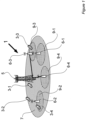
- FIG. 1 schematically illustrates a mobile (cellular) telecommunication system 1 in which a user of any of a plurality of mobile communication devices 3-1, 3-2, 3-3, 3-4, can communicate with other users via one or more of a plurality of base stations 5, 6-1, 6-2, 6-3, 6-4.
- each base station 5, 6 shown is an Evolved Universal Terrestrial Radio Access Network (E-UTRAN) base station capable of operating in a multi-carrier environment.
- E-UTRAN Evolved Universal Terrestrial Radio Access Network
- the base station labelled 5 comprises a so called 'macro' base station operating a relatively large 'macro' cell 7.
- the other base stations 6 shown in Figure 1 each comprises a so called small cell base station (possibly a so called 'pico' base station, ⁇ Remote Radio Head (RRH)', or other similar device capable of operating a small cell) operating a respective small cell 9-1, 9-2, 9-3, 9-4.
- RRH Remote Radio Head
- the power used to provide small cells 9 is low relative to the power used for the macro cell 7 and the small cells 9 are therefore small relative to the macro cell 7.
- the geographical coverage of each of the small cells 9 falls completely within the geographical coverage of the macro cell 7 although partially overlapping geographical coverage with the macro cell 7 is, of course, possible.
- the macro base station 5 is configured to provide discovery signals in each radio frame to allow a mobile communication device 3 to discover, and achieve synchronisation with, the macro base station 5. Specifically, the macro base station 5 transmits a discovery signal comprising a primary synchronisation signal (PSS) in a primary synchronisation channel (P-SCH) and a secondary synchronisation signal (SSS) in a secondary synchronisation channel (P-SCH), at predetermined fixed locations (in both frequency and time) within each radio frame, and hence at a fixed periodicity, as set out in 3GPP TS 36.211 V10.2.0.
- PSS primary synchronisation signal
- P-SCH primary synchronisation channel
- SSS secondary synchronisation signal
- the macro base station 5 is also configured to control operation of a 'cluster' comprising two small cell base stations 6-3 and 6-4 and hence their corresponding small cells 9-3, 9-4, that share a common physical cell identity (PCI), and group cell identity (and hence a common Cell ID which is defined by the PCI and group cell identity), although the macro base station 5, and each small cell base station 6-3, 6-4 of the cluster represent a different distinct transmission point.
- PCI physical cell identity
- group cell identity and hence a common Cell ID which is defined by the PCI and group cell identity
- Each small cell base station 6 is also configured to provide discovery signals on a physical discovery channel (PDCH) to allow a mobile communication device 3 to discover, and achieve synchronisation with, the small cell base station 6.
- PDCH physical discovery channel
- the discovery signals transmitted by each small base station 6 are not transmitted at a fixed periodicity but are, instead, transmitted at a flexible periodicity that can be configured, and reconfigured, by the small cell base station or the macro cell base station controlling the small cell base station 6.
- This extra flexibility is particularly beneficial because it allows a very wide range of periodicities (or 'repetition intervals') of anything from a few subframes to several hundred radio frames or greater to be configured thereby helping to ensure that small cell base stations can be configured to consume less power and the overhead introduced by discovery signals can be reduced in dependence on the configured periodicity. Further, even in the presence of a relatively dense population of small cell base stations 6 the chances of several respective PSS and SSS being transmitted at the same time (or within close temporal proximity to one another) for different small cell base stations, is relatively low.
- the discovery signals provided by each small cell base station 6 beneficially re-use the structure of the PSS and SSS used by the macro base station 5 thereby providing at least some backwards compatibility with legacy mobile communication devices.
- the discovery signals provided by each small cell base station 6 are, however, further enhanced: to reduce the size of the search window that the mobile communication device 3 needs to employ; to improve the speed with which a search can be carried out; to improve the reliability of a cell search procedure; to enhance time and/or frequency tracking; to allow measurement (e.g.
- RSRQ Reference Signal Received Quality
- RSRP Reference Signal Received Power
- the discovery signals are enhanced in the time domain by including additional PSS and/or SSS type signals in each subframe.
- the discovery signals are enhanced in the frequency domain by expanding the frequency range over which the PSS and/or SSS type signals are transmitted.
- the respective benefits of the different enhancements combine together to provide a greater cumulative benefit albeit at the expense of greater discovery signal overhead.
- the introduction of the new discovery signal (on the PDCH) therefore helps to facilitate the search for, acquisition of, and synchronisation with a small cell base station, by a mobile communication device 3.
- the new discovery signal is implemented, one or more of the following additional benefits arise compared, for example, with using a conventional P-SCH / S-SCH structure: power savings in mobile communication device and/or small cell base station; a relatively quick search for/discovery of a small cell; relatively rapid acquisition of measurement results for the purposes of handover, thereby facilitating rapid handover operations; and/or the support of a greater number of physical Cell IDs and/or dedicated transmission point identities.
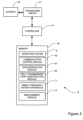
- FIG 2 is a block diagram illustrating the main components of a base station 5, 6 as shown in Figure 1 .
- the base station 5, 6 comprises an E-UTRAN multi-carrier capable base station comprising a transceiver circuit 31 which is operable to transmit signals to, and to receive signals from, the mobile communication devices 3 via at least one antenna 33.
- the base station 5, 6 is also operable to transmit signals to and to receive signals from: a core network via a network interface 35 (optionally via a small cell gateway or the like in the case of a small cell base station (not shown)); and other base stations 5, 6 in the vicinity via a base station (or so called ⁇ X2') interface 36.
- the operation of the transceiver circuit 31 is controlled by a controller 37 in accordance with software stored in memory 39.
- the software includes, among other things, an operating system 41, a communication control module 42, a synchronisation module 47, and a cell / transmission point identification module 49.
- the communication control module 42 is operable to control communication with the mobile communication devices 3 via the antenna 33 and with the core network and other base stations via the network interface 35 and the X2 interface 36 respectively.
- the synchronisation module 47 manages the generation and transmission of discovery signals at appropriate locations in a radio frame 210 (see Fig. 4 ) as required and, in the case of the small cell base station 6, the configuration and reconfiguration of the periodicity of the discovery signals, and the encoding of appropriate information into the discovery signal as appropriate.
- the cell / transmission point identification module 49 generates identification information for the cell / transmission point such as the Cell ID (cell group ID / physical cell ID (PCI)) and/or transmission point ID (e.g. for small cells sharing the same Cell ID as other cells in a cluster of cells) for encoding into the discovery signals by the synchronisation module 47.
- the Cell ID cell group ID / physical cell ID (PCI)
- PCI physical cell ID
- the base station 5 is described for ease of understanding as having a number of discrete modules. Whilst these modules may be provided in this way for certain applications, for example where an existing system has been modified to implement the invention, in other applications, for example in systems designed with the inventive features in mind from the outset, these modules may be built into the overall operating system or code and so these modules may not be discernible as discrete entities.
- FIG 3 is a block diagram illustrating the main components of the mobile communication devices 3 shown in Figure 1 .
- Each mobile communication device 3 comprises a mobile (or 'cell' telephone) capable of operating in a multi-carrier environment.
- the mobile communication device 3 comprises a transceiver circuit 51 which is operable to transmit signals to, and to receive signals from, the base stations 5, 6 via at least one antenna 53.
- the operation of the transceiver circuit 51 is controlled by a controller 57 in accordance with software stored in memory 59.
- the software includes, among other things, an operating system 51, a communication control module 62, a synchronisation module 67, a cell / transmission point identification module 69, a timing / frequency estimation module 71 and a measurement module 73.
- the communication control module 62 is operable for managing communication with the base stations 5, 6.
- the synchronisation module 67 manages synchronisation of the mobile communication device 3 with the radio frame / subframe timing of the base station 5, 6.
- the synchronisation module 67 also manages the identification of the discovery signal configuration such as the location of the PSS/SSS within each radio frame 210 (see Fig. 4 ) and the decoding of appropriate information from the discovery signal as appropriate.
- the cell / transmission point identification module 69 determines identification information for the cell / transmission point such as the Cell ID (cell group ID / PCI) and/or transmission point ID (e.g. for small cells sharing the same Cell ID as other cells in a cluster of cells) from the information encoded into the discovery signals by the synchronisation module 67.
- the timing / frequency estimation module 71 is configured for performing timing and/or frequency estimation using the discovery signals generated and transmitted by the small cell base station 6.
- the measurement module 73 is configured for performing measurements (e.g. RSRP / RSRQ measurements) on the discovery signals generated and transmitted by the small cell base station 6.
- the mobile communication device 3 is described for ease of understanding as having a number of discrete modules. Whilst these modules may be provided in this way for certain applications, for example where an existing system has been modified to implement the invention, in other applications, for example in systems designed with the inventive features in mind from the outset, these modules may be built into the overall operating system or code and so these modules may not be discernible as discrete entities.
- FIG 4 illustrates the structure of a radio frame 210 of the type used for communication by the base stations 5, 6 and mobile communication devices 3 of the mobile (cellular) telecommunication system 1.
- each base station 5 is configured to transmit control information and data to associated mobile communication devices using radio frames 210.
- Each radio frame 210 in this exemplary embodiment, is 10ms long and as seen in Figure 4 comprises a plurality of orthogonal frequency division multiplexing (OFDM) subframes 230 (in this exemplary embodiment ten 1ms subframes which are indexed '0' through '9' make up a radio frame 210).
- Each subframe comprises a pair of slots 232a and 232b (in this exemplary embodiment 0.5ms long).
- OFDM orthogonal frequency division multiplexing
- the slots 232 are typically referred to by index numbers ranging from '0' to '19' in chronological order (from left to right on Figure 4 ) with the first slot 232a of each subframe 230 having an even number and the second slot 232b having an odd number.
- Part of the first ('even numbered') slot of each subframe 230 comprises a so called 'control' region 231 that is generally reserved for the transmission of control information.
- the remainder of the first ('even numbered') slot of each subframe 230 and the second ( ⁇ odd numbered') slot of each subframe 230 comprises a so called 'data' region 233 that is generally used for the transmission of data, for example in a Physical Downlink Shared Channel (PDSCH).
- PDSCH Physical Downlink Shared Channel
- Figure 5 shows a resource grid for part of one of the OFDM subframes 230 of Figure 4 .
- the resource grid shown is for a resource block (RB) pair 310a, 310b (represented by hatched region) with each RB 3 10a, 310b of the pair having, for example, a resource grid similar to that described in section 6.2 of the 3 rd Generation Partnership Project (3GPP) Technical Standard (TS) 36.211 V10.2.0 and shown in Figure 6 . 2 .2-1 of that standard.
- 3GPP 3 rd Generation Partnership Project
- TS Technical Standard
- each resource block 310a and 310b is part of a respective slot 232a and 232b of the subframe 230.
- Each resource block 310a, 310b comprises a set of resource elements 335 defined in frequency by 12 subcarrier frequencies (rows) and in time by 7 symbols (columns).
- the control region 231 comprises the resource elements 335 of the first three OFDM symbols of the first slot 232a of each subframe 230.
- the remaining resource elements 335 of the first slot 232a and the resource elements 335 of the second slot 232b form the data region 333.
- each base station 5, 6 is configured to provide discovery signals at particular locations (in frequency and time) in corresponding radio frames 210 to allow the mobile communication device 3 to discover and achieve synchronisation with the base station 5, 6.
- Each discovery signal comprises a PSS that can be used by the mobile communication device 3 to synchronise receipt and transmission of each symbol, slot and subframe with the corresponding symbol, slot and/or subframe timings of the corresponding base station 5, 6. Further, the PSS is also used by the mobile communication device 3 to identify other information about the cell to which it relates, for example, cell identity information such as a physical layer cell identity (PCI).
- Each discovery signal also comprises an SSS that is used by the mobile communication device 3 to synchronise receipt and transmission of each radio frame 210 with the associated frame timings of the corresponding base station 5, 6: The SSS is also used by the mobile communication device 3 to identify other information about the cell to which they relate, for example cell group identity information such as the physical layer cell identity group for the base station 5, 6.
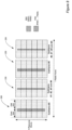
- Figure 6 illustrates how the discovery signals are configured in the radio frames 230 for the macro cell 7 of the macro base station 5.
- the macro base station 5 always provides the synchronisation signals (PSS/SSS) in the last two symbols of the first (even numbered) slot 232a in the first subframe 230 (subframe #0) and in the last two symbols of the first (even numbered) slot 232a in the sixth subframe 230 (subframe #5).
- PSS is transmitted in the last symbol of the first slot 232a of the first and sixth subframes
- SSS is transmitted in the second to last symbol of the first slot 232a of the first and sixth subframes 230 (i.e. the last symbol of slot #0 and slot #10).
- the PSS and SSS are each allocated the central 62 subcarriers belonging to symbols in which they are respectively located.
- the 5 resource elements above and below the synchronisation signals are not used for transmission and hence the PSS and SSS each account for the central 72 subcarriers (6 resource blocks).
- the PSS and SSS transmissions each use six resource blocks (with 10 resource elements left unused) and the indexes of the resource blocks (resource block numbers) within the frequency band covered by the macro cell 7 are always the same.
- the sequence d (0),..., d (61) used for the SSS comprises an interleaved concatenation of two length-31 binary sequences.
- the concatenated sequence is scrambled with a scrambling sequence given by the PSS.
- the indices m 0 and m 1 are derived from the physical-layer cell-identity group.
- the two PSS transmissions within a radio frame 210 are identical.
- the two SSS transmissions within each radio frame 210 (referred to as SS1 and SS2), however, use different sequences to allow the mobile communication device 3 to differentiate between the 1 st and 2 nd transmission thereby allowing the mobile communication device 3 to achieve frame synchronisation.
- each small cell base station 6 of this exemplary embodiment still provides discovery signals comprising synchronisation signals (PSS/SSS) encoded in the same manner as for the macro cell, the periodicity with which the small cell base station 6 transmits the discovery signals is individually configurable by each small cell base station 6.
- PSS/SSS synchronisation signals
- the periodicity 'T DS ' is set to a suitable number of radio frames (e.g. 50, 100, 200, 1000, 2000 or any other appropriate number). Accordingly, as seen in Figure 7 , when the first discovery signal is transmitted in radio fame number 'n', the next discovery signal is transmitted in radio fame number 'n + T DS ', the next in radio fame number ⁇ n + 2.T DS ' and so on. More specifically, the discovery signal is transmitted in radio fame number 'n + r.T DS ' where r is an integer that starts at zero for radio fame number 'n' and increments by one for each subsequent radio fame in which the discovery signal is transmitted.
- r is an integer that starts at zero for radio fame number 'n' and increments by one for each subsequent radio fame in which the discovery signal is transmitted.
- FIG. 7 shows a configuration based on a periodicity defined in terms of a number of radio frames
- a configuration based on a periodicity defined in terms of a number of subframes is also possible (e.g. where the first discovery signal is transmitted in subfame number 'n', the next discovery signal is transmitted in subfame number 'n + T SF DS ', the next in subfame number ⁇ n + 2. T SF DS ' and so on).
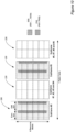
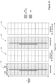
- Figure 8 illustrates an exemplary radio frame, transmitted by a small cell base station 6, in which the discovery signal is enhanced in the time domain.
- the discovery signal comprises a set of four extra PSSs (PSS2, ..., PSS5) that are transmitted in, and distributed throughout, each 5ms half of the 10ms radio frame in which the discovery signal is provided.
- the additional PSSs (PSS2, ..., PSS5) are transmitted at regular intervals in consecutive subframes.
- the additional PSSs (PSS2, ..., PSS5) are each shown to be transmitted in the last symbol of the first (even numbered) slot of a respective one of subframes #1 to #4 and then repeated in the last symbol of the first (even numbered) slot of a respective one of subframes #6 to #9. It will be appreciated, however, that the new PSSs could be transmitted in other symbols.
- each additional PSS (PSS2, ..., PSS5) has a respective Zadoff-Chu root sequence index to differentiate it from the legacy PSS (PSS1) transmitted in subframes #0 and #5. It will be appreciated, however, that any or all of the new PSSs could simply be a repetition of the existing PSS if differentiation is not required.
- Figures 9 and 10 each illustrates another exemplary radio frame, transmitted by a small cell base station 6, in which the discovery signal is enhanced in the time domain.
- the discovery signal comprises a second pair of synchronisation signals in the respective second (odd) slot of each of the first and sixth subframes, i.e., 0.5ms apart from the corresponding legacy pair of synchronisation signals.
- the close proximity of the legacy and the new synchronisation signals in this exemplary embodiment beneficially allows frequency estimation to be performed, using the discovery signal, without requiring the use of cell specific reference signals (CRS), thereby improving efficiency compared to current systems.
- CRS cell specific reference signals
- the second pair of synchronisation signals in each of the first and sixth subframes comprises a pair of PSSs (PSS2 & PSS3) whereas in the example of Figure 10 the second pair of synchronisation signals in each of the first and sixth subframes comprises an additional SSS (SSS3 & SSS4) followed by an additional PSS (PSS2).
- each additional PSS PSS2 / PSS3 and/or SSS (SSS3, SSS4) has a respective Zadoff-Chu root sequence index to differentiate it from its legacy counterpart. It will be appreciated, however, that any or all of the new synchronisation signals could simply be a repetition of the corresponding legacy synchronisation signal if differentiation is not required.
- the close proximity of the legacy and the new synchronisation signals beneficially allows frequency estimation to be performed, using the discovery signal, without requiring the use of cell specific reference signals (CRS), thereby improving efficiency compared to current systems.
- CRS cell specific reference signals
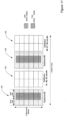
- Figure 11 illustrates another exemplary radio frame, transmitted by a small cell base station, in which the discovery signal is enhanced in the time domain.
- the discovery signal comprises a set of four extra PSSs (PSS2, ..., PSS5) that are transmitted over consecutive symbols following the respective legacy PSS (PSS1) in the respective second (odd) slot of each of the first and sixth subframes.
- This discovery signal format is particularly beneficial in helping a mobile communication device 3 to quickly detect the timing reference in a cell search process, and like the previous examples, helps to improve time and frequency estimation performance and measurement quality.
- each additional PSS (PSS2, ..., PSS5) has a respective Zadoff-Chu root sequence index to allow differentiation from its legacy counterpart. It will be appreciated, however, that any or all of the new synchronisation signals could simply be a repetition of the corresponding legacy synchronisation signal if differentiation is not required. It will be further appreciated that each SSS (SSS1 and SSS2) may use the same or a different Zadoff-Chu root sequence index.
- Figure 12 illustrates another exemplary radio frame, transmitted by a small cell base station 6, in which the discovery signal is enhanced in the time domain.
- the discovery signal in addition to the legacy PSS (PSS1) and SSS (SSS1) transmitted in the first (even) slot of the first subframe (#0), the discovery signal comprises a second discovery signal part comprising a pair of signals in the respective second (odd) slot of the first subframe, i.e., 0.5ms apart from the corresponding legacy pair of synchronisation signals in that subframe.
- the second set of signals in the example of Figure 12 is formed by wrapping/multiplexing an additional PSS/SSS (e.g. as described for the first subframe with reference to Figures 9 or 10 ) with a masking code such as an orthogonal code, or a cyclically shifted version of a Zadoff-Chu sequence, to encode a unique identifier for the small cell (e.g. a 'small cell ID' or 'transmission point ID') e.g. within a cluster of small cells having the same Cell ID encoded into the legacy PSS/SSS.
- a masking code such as an orthogonal code, or a cyclically shifted version of a Zadoff-Chu sequence
- a modified mobile communication device 3 can detect the Cell ID and also derive each small cell / transmission point ID within the cluster based on the second discovery signal part whilst a legacy mobile communication device can still detect the Cell ID.
- the second discovery signal part can also be used to identify the status of the detected cell, such as dormancy/cell load, e.g., by encoding cell dormancy (i.e., load zero) / cell load information together with appropriate identification information in the second discovery signal part.
- dormancy/cell load e.g., by encoding cell dormancy (i.e., load zero) / cell load information together with appropriate identification information in the the second discovery signal part.
- the two signals of the second discovery signal part can be the same or different.
- Figure 13 illustrates another exemplary radio frame, transmitted by a small cell base station 6, in which the discovery signal is enhanced in the time domain.
- the discovery signal comprises a second discovery signal part comprising a set of four extra signals that are transmitted over consecutive symbols following the legacy PSS (PSS) in the second (odd) slot of the first subframe.
- the second set of signals in the example of Figure 13 is formed by wrapping/multiplexing an additional PSS/SSS (e.g. as described for the first subframe with reference to Figures 9 or 10 ) with a masking code such as an orthogonal code, or a cyclically shifted version of a Zadoff-Chu sequence, to encode a unique identifier for the small cell (e.g. a ⁇ small cell ID' or 'transmission point ID') e.g. within a cluster of small cells having the same Cell ID encoded into the legacy PSS/SSS.
- a masking code such as an orthogonal code, or a cyclically shifted version of a Zadoff-Chu sequence
- a modified mobile communication device 3 can detect the Cell ID and also derive each small cell / transmission point ID within the cluster based on the second discovery signal part whilst a legacy mobile communication device can still detect the Cell ID.
- the enhancement beneficially allows time estimation, frequency estimation and RSRP/RSRQ measurements to be carried out in addition to fast cell discovery.
- timing estimation is performed by correlating in the frequency domain a transmitted signal with its replica at the receiver and accumulating the energy of the correlation over a number of OFDM symbols in the time-domain, and detecting the maximum peak of the accumulated correlator output among correct timing candidates within a pre-defined window of timing hypotheses.
- the close proximity of the synchronisation signals in the above exemplary discovery signals allows frequency estimation to be performed based on a pair of the signals forming the discovery signal (e.g. the PSS, SSS, and/or one or more of the signals forming the second part of the discovery signal) without the need to use other reference signals such as cell specific reference signals (CRS).
- a pair of the signals forming the discovery signal e.g. the PSS, SSS, and/or one or more of the signals forming the second part of the discovery signal
- CRS cell specific reference signals
- a set of frequency estimates may be calculated using the first and second SSS of one subframe, and another set of frequency estimates may be calculated using the first and second PSS in the same subframe. These estimates may then be combined to provide more reliable estimates, avoiding the need to use CRS for that purpose (and potentially improving on estimates using CRS).
- the additional reference signals (comprising synchronisation signals / other dedicated signals) in the discovery signals in the time domain allows such measurements to be performed more efficiently and reliably.
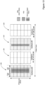
- Figures 14 and 15 each illustrate an exemplary radio frame, transmitted by a small cell base station 6, in which the discovery signal is enhanced in the frequency domain.
- the primary synchronisation signal is enhanced by transmitting it over 12 resource blocks rather than 6 resource blocks.
- the central 6 resource blocks in this case correspond to the legacy PSS (for example for use in identifying the Cell ID).
- both the primary synchronisation signal (PSS) and the secondary synchronisation signal (SSS) are enhanced by transmitting each over 12 resource blocks rather than 6 resource blocks.
- the central 6 resource blocks correspond to the respective legacy SSS and PSS (for example for use in identifying the Cell ID).
- the enhancement beneficially allows time estimation and RSRP/RSRQ measurements to be carried out in addition to fast cell discovery.
- the additional reference signals (comprising synchronisation signals / other dedicated signals) in the discovery signals in the frequency domain allows such measurements to be performed more efficiently and reliably.
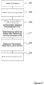
- Figure 16 shows a flow chart illustrating one method by which a small cell base station 6 may generate and transmit a discovery signal for discovery by the mobile communication device 3 in a cell search procedure for cell discovery purposes in the above exemplary embodiments.
- Figure 17 shows a flow chart illustrating one method by which a mobile communication device 3 may use the discovery signal in a cell search procedure for cell discovery purposes in the above exemplary embodiments.
- Figure 18 shows a flow chart illustrating another, more detailed, method by which a small cell base station 6 may generate and transmit a discovery signal for discovery by the mobile communication device 3 in a cell search procedure for cell discovery purposes.
- the flow chart is particularly relevant to the examples of Figures 12 and 13 where Cell ID and small cell ID/TP ID are encoded separately.
- Figure 19 shows a flow chart illustrating another, more detailed, method by which a mobile communication device 3 may use the discovery signal in a cell search procedure for cell discovery purposes.
- the flow chart is particularly relevant to the examples of Figures 12 and 13 where Cell ID and small cell ID/TP ID are encoded separately.
- a discovery signal at the configured periodicity, comprising just one pair of PSS and SSS (e.g. not including the PCC / SSS2 typically sent in the sixth subframe).
- a discovery signal at the configured periodicity, comprising just one pair of PSS and SSS (e.g. not including the PCC / SSS2 typically sent in the sixth subframe).
- the discovery signal can carry the current Cell ID or a different ID such as a dedicated transmission point ID ( ⁇ TP ID') or ⁇ small cell ID' which can be used to distinguish different small cells within a small cell cluster having the the same Cell ID.
- a dedicated transmission point ID ⁇ TP ID'
- ⁇ small cell ID' which can be used to distinguish different small cells within a small cell cluster having the the same Cell ID.
- the macro cell can allocate a different ID to each small cell within the cluster, and the mobile communication device can detect and report it to the macro cell which can then identify which small cell the mobile communication device has detected based on the reported ID.
- the proposed structures can beneficially provide more physical Cell IDs than the 504 of the current system by introducing new code sequences for the discovery signal (first and second parts).
- the proposed structures do not depend on the size of the system bandwidth because the discovery signals are located in the central 6 or 12 RBs.
- the proposed structures beneficially provide backward compatibility for legacy mobile communication devices by keeping the existing PSS and SSS in the central 6 RBs.
- a dedicated small cell PSS/SSS configuration could be defined having any suitable PSS/SSS configuration, for example, a configuration in which the SSS and PSS were reversed.
- the PCI / cell group ID may be used to represent a small cell ⁇ Cluster ID' (e.g. which is equivalent to a Cell ID that is shared by the plurality of cells in the cluster) and may thus be transmitted on the existing PSS/SSS.
- a dedicated transmission point ID ('TP ID') or 'small cell ID' within the cluster may then be transmitted using the second part of the discovery signal. Therefore, a mobile communication device can detect a cluster ID first using only the legacy PSS/SSS signal and then can detect a TP ID within the cluster using the second part of the discovery signal.
- a single ⁇ global TP ID' or ⁇ global Cell ID' may be transmitted which the mobile communication device can detect in one step using all the transmitted discovery signals. This may, for example, be faster than the using separate a Cell ID/Cluster ID and TP ID / small cell ID, but the search complexity may be increased because there are more possible IDs to be searched.
- Part or all of a discovery signal could be transmitted on a different carrier frequency from that of the legacy PSS/SSS, for example on the same carrier as the macro cell. This would allow mobile communication devices camped on the macro cell to search for small cells using intra-frequency search and measurements instead of inter-frequency search and measurements, thus reducing mobile communication device complexity.
- the proposed discovery signals need not be used only for cell search, but also for other purposes such as time/frequency estimation and RSRP/RSRQ measurements, thus reducing mobile communication device complexity as well as downlink reference signal transmission overhead.
- the discovery signal can carry the status information of the detected cell, such as dormancy/cell load, e.g., by encoding cell dormancy (i.e., load zero) / cell load information together with appropriate identification information in the the second discovery signal part.
- Similar signalling structures may also be applied to device to device (D2D) and machine type communications (MTC) in order to identify other devices or TP (transmission point) / RP (reception point) in Coordinated Multi-Point (CoMP) transmission/reception scenarios.
- D2D device to device
- MTC machine type communications
- TP transmission point
- RP reception point
- CoMP Coordinated Multi-Point
- the communication system 1 is described in terms of base stations 5 operating as macro or small cell base stations, the same principles may be applied to base stations operating as femto base stations, relay nodes / UE-Relays providing elements of base station functionality, or other such communication nodes.
- a mobile telephone based telecommunications system was described.
- the signalling techniques described in the present application can be employed in other communications systems.
- Other communications nodes or devices may include user devices such as, for example, personal digital assistants, laptop computers, web browsers, etc.
- the system can be used to extend the coverage of base stations in a network having one or more fixed computing devices as well as or instead of the mobile communicating devices.
- the base stations 5, 6 and mobile communication devices 3 each include transceiver circuitry.
- this circuitry will be formed by dedicated hardware circuits.
- part of the transceiver circuitry may be implemented as software run by the corresponding controller.
- the software modules may be provided in compiled or un-compiled form and may be supplied to the base station or the relay station as a signal over a computer network, or on a recording medium. Further, the functionality performed by part or all of this software may be performed using one or more dedicated hardware circuits.
Landscapes
- Engineering & Computer Science (AREA)
- Computer Networks & Wireless Communication (AREA)
- Signal Processing (AREA)
- Databases & Information Systems (AREA)
- Computer Security & Cryptography (AREA)
- Mobile Radio Communication Systems (AREA)
- Time-Division Multiplex Systems (AREA)
Abstract
Description
- The present invention relates to mobile communications devices and networks, particularly but not exclusively those operating according to the 3rd Generation Partnership Project (3GPP) standards or equivalents or derivatives thereof. The invention has particular although not exclusive relevance to the Long Term Evolution (LTE) of UTRAN (called Evolved Universal Terrestrial Radio Access Network (E-UTRAN)).
- In 3GPP LTE networks, a base station (i.e. evolved NodeB, eNB) of a Radio Access Network (RAN) transmits data and signalling between a core network (CN) and User Equipment (UEs) located within the base station's coverage area.
- Developments in communication networks have seen increased deployment of so called 'small' cells operated by Low Power Nodes (LPNs), such as pico eNBs, femto cells, Home eNBs (HeNBs) or the like, which cells have a smaller coverage area than existing macro cells operated by a higher power macro base station. Networks comprising a number of different cell types, for example a network comprising a macro cell and a femto cell, are referred to as Heterogeneous Networks, or HetNets.
- More recently the need to make further enhancements to small cells using low-power nodes, has been identified as one of the most important topics for further development of 3GPP standards compliant communication systems in order to enable such communication systems to cope with increases in mobile traffic especially for hotspot deployments in indoor and outdoor scenarios. According to this interest in small cell enhancements, scenarios and requirements for small cell enhancements were studied and captured in a 3GPP technical report (3GPP TR 36.932) the contents of which are herein incorporated by reference. TR 36.932 defines a low-power node as generally meaning a node whose transmit power is lower than that of macro node and base station classes. For example, as indicated above, both pico eNB and femto HeNBs are considered to be low power nodes.
- Currently, the average geographic density of macro cells is 5-7 macro cells per square kilometre. However, it is predicted that the number of small cells in urban areas will reach 40 small cells per square kilometre. The increasing geographic density of small cells presents challenges in achieving successful and efficient handover procedures in HetNets. In a densely deployed small cell scenario for example, the number of small cells a piece of user equipment (UE) such as a mobile ('cellular') telephone or other similar mobile device should detect and measure for the purposes of mobility management (e.g. management of the smooth transfer from one cell to another) can be much larger than that of other macro cell or less dense HetNet scenarios.
- Accordingly whilst, in the conventional LTE systems up to the latest Release 11, the use of Synchronisation Channels (SCH) which consist of a Primary Synchronisation Channel (P-SCH) and a Secondary Synchronisation Channel (S-SCH) can be used to help the UE to search, acquire, and synchronise with an eNB, it is generally accepted that the SCHs will be unable to cope with such a densely populated cell deployment scenario. Specifically, there are a number of other issues that need to be considered for a densely populated small cell environment including, for example: how to ensure efficient use of power; the speed of the search for/discovery of a small cell; the ability to identify the cells; and/or the ability to acquire measurement results for the purposes of handover.
- Accordingly, preferred embodiments of the present invention aim to provide methods and apparatus which overcome or at least alleviate one or more of the above issues.
- In one aspect of the invention there is provided communication apparatus for communicating with a mobile communication device in a communication system which uses a plurality of radio frames wherein each radio frame is subdivided in the time domain into a plurality of subframes, each subframe is subdivided in the time domain into a plurality of slots, and each slot is subdivided in the time domain into a plurality of symbols, said communication apparatus comprising: cell operating means for operating a communication cell; discovery signal generating means for generating discovery signals, for use in a cell search procedure, each discovery signal comprising a pair of synchronisation signals and at least one further signal; and transmitting means for transmitting each of said pair of synchronisation signals and said at least one further signal in a respective symbol of a radio frame; wherein said symbol in which said at least one further signal is transmitted separated, in the time domain, by no more than half a radio frame from at least one of said pair of synchronisation signals.
- The transmitting means may be operable to transmit said at least one further signal in a different subframe to said pair of synchronisation signals.
- The at least one further signal may comprise a plurality of further signals and wherein said transmitting means may be operable to transmit each of said plurality of further signals in a different respective subframe.
- The transmitting means may be operable to transmit said at least one further signal in the same subframe as said pair of synchronisation signals.
- The transmitting means may be operable to transmit said at least one further signal in a different slot to said pair of synchronisation signals.
- The transmitting means may be operable to transmit said at least one further signal at a separation, in the time domain, of a single slot from one of said pair of synchronisation signals.
- The transmitting means may be operable to transmit the, or at least one, further signal in a symbol that is adjacent, in the time domain, to the symbol in which one of said pair of synchronisation signals is transmitted.
- The at least one further signal may comprise a plurality of further signals and wherein said transmitting means may be operable to transmit each of said plurality of further signals in a symbol that is adjacent at least one other symbol in which one of said plurality of further signals is transmitted.
- The pair of synchronisation signals may comprise at least one of a primary synchronisation signal (PSS) and a secondary synchronisation signal (SSS).
- The pair of synchronisation signals may comprise a primary synchronisation signal (PSS) and a secondary synchronisation signal (SSS).
- The at least one further signal may comprise at least one of a primary synchronisation signal (PSS) and a secondary synchronisation signal (SSS).
- The at least one further signal may comprise a primary synchronisation signal (PSS) and a secondary synchronisation signal (SSS).
- The at least one further signal may comprise at least one signal that is different to a primary synchronisation signal (PSS) and/or a secondary synchronisation signal (SSS).
- The cell operating means may be operable to operate said cell as one cell of a cluster of cells each cell of which shares a common cell identifier (or 'cluster identifier'); said discovery signal generating means is operable to encode an identifier for said one cell into at least one of said pair of synchronisation signals and said at least one further signal; and wherein said identifier for said one cell is unique at least within said cluster of cells.
- The discovery signal generating means may be operable to encode said common cell identifier (or 'cluster identifier') into at least one of said pair of synchronisation signals and said identifier for said one cell into said at least one further signal.
- The discovery signal generating means may be operable to encode said common cell identifier (or 'cluster identifier') into said pair of synchronisation signals by encoding a cell group identifier into a first of said pair of synchronisation signals and a physical layer cell identity (PCI), identifying the cell within a cell group represented by the cell group identifier, into a second of said pair of synchronisation signals.
- The identifier for said one cell, said cell group identifier, and said PCI together may provide a global identifier for said one cell.
- The discovery signal generating means may be operable to encode said identifier for said one cell, as a global identifier for said one cell that does not depend on the common cell identifier, into at least one of said pair of synchronisation signals and said at least one further signal.
- Each of said radio frame may be divided, in the frequency domain into a plurality of resource blocks, each resource block being divided, in the frequency domain, into a plurality of sub-carriers, wherein at least one of said pair of synchronisation signals and said at least one further signal may extend across more than six resource blocks in the frequency domain.
- The at least one of said pair of synchronisation signals and said at least one further signal may extend into at least twelve resource blocks in the frequency domain.
- According to another aspect of the invention there is provided a communication apparatus for communicating with a mobile communication device in a communication system which uses a plurality of radio frames wherein each radio frame is subdivided in the time domain into a plurality of subframes, each subframe is subdivided in the time domain into a plurality of slots, and each slot is subdivided in the time domain into a plurality of symbols, said communication apparatus comprising: means for operating a communication cell as one cell of a cluster of cells each cell of which shares a common cell group identifier, and a common physical cell identity (PCI), which cell group identifier and common PCI together form a shared common cell identifier (or 'cluster identifier'); discovery signal generating means for generating discovery signals, for use in a cell search procedure, each discovery signal comprising at least a pair of synchronisation signals and encoding an identifier for said one cell, wherein said identifier for said one cell is unique at least within said cluster of cells; and means for transmitting each of said pair of synchronisation signals in a respective symbol of a radio frame.
- The discovery signal generating means may be operable to encode said shared common cell identifier (or 'cluster identifier') into at least one of said pair of synchronisation signals and said identifier for said one cell into at least one further signal forming part of said discovery signal.
- The discovery signal generating means may be operable to encode said shared common cell identifier (or 'cluster identifier') into said pair of synchronisation signals by encoding a cell group identifier into a first of said pair of synchronisation signals and a physical layer cell identity (PCI), identifying the cell within a cell group represented by the cell group identifier, into a second of said pair of synchronisation signals.
- The identifier for said one cell, said cell group identifier, and said PCI together may provide a global identifier for said one cell.
- The discovery signal generating means may be operable to encode said identifier for said one cell, as a global identifier for said one cell that does not depend on the common cell identifier, into said discovery signal.
- Communication apparatus for communicating with a mobile communication device in a communication system which uses a plurality of radio frames wherein each radio frame is subdivided in the time domain into a plurality of subframes, said communication apparatus comprising: means for operating a communication cell; means for generating discovery signals for use in a cell search procedure, each discovery signal comprising at least one synchronisation signal; configuring means for configuring a periodicity at which said communication apparatus should transmit said discovery signals wherein said configuring means is operable, when configuring said periodicity, to select said periodicity from any of a plurality of possible periodicities; and means for transmitting said discovery signals at said configured periodicity.
- The configuring means may be operable to configure a periodicity comprising a plurality of radio frames.
- The configuring means may be operable to configure a periodicity comprising a plurality of subframes.
- The configuring means may be operable, when configuring said periodicity, to select said periodicity from a range of possible periodicities.
- The range of possible periodicities may extend beyond 50 radio frames (or 50 subframes).
- According to one aspect of the invention there is provided a mobile communication device for communicating with communication apparatus in a cellular communication system using a plurality of radio frames wherein each radio frame is subdivided in the time domain into a plurality of subframes, each subframe is subdivided in the time domain into a plurality of slots, and each slot is subdivided in the time domain into a plurality of symbols, said mobile communication device comprising: means for performing a cell search procedure to discover a communication cell controlled by said communication apparatus; means for receiving a discovery signal as part of said cell search procedure, wherein said discovery signal comprises a pair of synchronisation signals and at least one further signal, and wherein a symbol in which said at least one further signal is transmitted is separated, in the time domain, by no more than half a radio frame from at least one of said pair of synchronisation signals.; and means for identifying, and synchronising with, said cell based on said pair of synchronisation signals and said at least one further signal in said discovery signal.
- The mobile communication device may comprise means for performing frequency estimation based on said pair of synchronisation signals and at least one further signal in said discovery signal.
- According to another aspect of the invention a mobile communication device for communicating with communication apparatus in a cellular communication system using a plurality of radio frames wherein each radio frame is subdivided in the time domain into a plurality of subframes, each subframe is subdivided in the time domain into a plurality of slots, and each slot is subdivided in the time domain into a plurality of symbols, said mobile communication device comprising: means for performing a cell search procedure to discover a communication cell, controlled by said communication apparatus, as one cell of a cluster of cells each cell of which shares a common cell group identifier, and a common physical cell identity (PCI), which cell group identifier and common PCI together form a shared common cell identifier (or 'cluster identifier'); means for receiving a discovery signal as part of said cell search procedure, wherein said discovery signal comprises at least a pair of synchronisation signals and encoding an identifier for said one cell, wherein said identifier for said one cell is unique at least within said cluster of cells; and means for identifying said cell by extracting said identifier for said one cell from said discovery signal and for synchronising with said one cell based on said pair of synchronisation signals.
- According to another aspect of the invention there is provided a communication system comprising at least one communication apparatus and at least one mobile communication device each according to one of the associated aspects disclosed herein.
- According to another aspect of the invention there is provided a computer program product which may comprise instructions operable to program a programmable processor to implement communication apparatus or a communication device.
- According to another aspect of the invention there is provided a method performed by communication apparatus for communicating in a communication system which uses a plurality of radio frames wherein each radio frame is subdivided in the time domain into a plurality of subframes, each subframe is subdivided in the time domain into a plurality of slots, and each slot is subdivided in the time domain into a plurality of symbols, said method comprising: operating a communication cell; generating discovery signals, for use in a cell search procedure, each discovery signal comprising a pair of synchronisation signals and at least one further signal; and transmitting each of said pair of synchronisation signals and said at least one further signal in a respective symbol of a radio frame; wherein said symbol in which said at least one further signal is transmitted separated, in the time domain, by no more than half a radio frame from at least one of said pair of synchronisation signals.
- According to another aspect of the invention there is provided a method performed by communication apparatus for communicating in a communication system which uses a plurality of radio frames wherein each radio frame is subdivided in the time domain into a plurality of subframes, each subframe is subdivided in the time domain into a plurality of slots, and each slot is subdivided in the time domain into a plurality of symbols, said method comprising: operating a communication cell as one cell of a cluster of cells each cell of which shares a common cell group identifier, and a common physical cell identity (PCI), which cell group identifier and common PCI together form a shared common cell identifier (or 'cluster identifier'); generating discovery signals, for use in a cell search procedure, each discovery signal comprising at least a pair of synchronisation signals and encoding an identifier for said one cell, wherein said identifier for said one cell is unique at least within said cluster of cells; and transmitting each of said pair of synchronisation signals in a respective symbol of a radio frame.
- According to another aspect of the invention there is provided a method performed by communication apparatus for communicating in a communication system which uses a plurality of radio frames wherein each radio frame is subdivided in the time domain into a plurality of subframes, said method comprising: operating a communication cell; generating discovery signals for use in a cell search procedure, each discovery signal comprising at least one synchronisation signal; configuring a periodicity at which said communication apparatus should transmit said discovery signals wherein, when configuring said periodicity, said periodicity is selected from a plurality of possible periodicities; and transmitting said discovery signals at said configured periodicity.
- According to another aspect of the invention there is provided a method performed by a mobile communication device for communicating with communication apparatus in a communication system which uses a plurality of radio frames wherein each radio frame is subdivided in the time domain into a plurality of subframes, each subframe is subdivided in the time domain into a plurality of slots, and each slot is subdivided in the time domain into a plurality of symbols, said method comprising: performing a cell search procedure to discover a communication cell controlled by said communication apparatus; receiving a discovery signal as part of said cell search procedure, wherein said discovery signal comprises a pair of synchronisation signals and at least one further signal, and wherein a symbol in which said at least one further signal is transmitted is separated, in the time domain, by no more than half a radio frame from at least one of said pair of synchronisation signals.; and identifying, and synchronising with, said cell based on said pair of synchronisation signals and at least one further signal in said discovery signal.
- According to another aspect of the invention there is provided a method performed by a mobile communication device for communicating with communication apparatus in a communication system which uses a plurality of radio frames wherein each radio frame is subdivided in the time domain into a plurality of subframes, each subframe is subdivided in the time domain into a plurality of slots, and each slot is subdivided in the time domain into a plurality of symbols, said method comprising: performing a cell search procedure to discover a communication cell, controlled by said communication apparatus, as one cell of a cluster of cells each cell of which shares a common cell group identifier, and a common physical cell identity (PCI), which cell group identifier and common PCI together form a shared common cell identifier (or 'cluster identifier'); receiving a discovery signal as part of said cell search procedure, wherein said discovery signal comprises at least a pair of synchronisation signals and encoding an identifier for said one cell, wherein said identifier for said one cell is unique at least within said cluster of cells; and identifying said cell by extracting said identifier for said one cell from said discovery signal and for synchronising with said one cell based on said pair of synchronisation signals.
- Aspects of the invention extend to computer program products such as computer readable storage media having instructions stored thereon which are operable to program a programmable processor to carry out a method as described in the aspects and possibilities set out above or recited in the claims and/or to program a suitably adapted computer to provide the apparatus recited in any of the claims.
- Each feature disclosed in this specification (which term includes the claims) and/or shown in the drawings may be incorporated in the invention independently (or in combination with) any other disclosed and/or illustrated features. In particular but without limitation the features of any of the claims dependent from a particular independent claim may be introduced into that independent claim in any combination or individually.
- Embodiments of the invention will now be described by way of example only with reference to the attached figures in which:
-
Figure 1 schematically illustrates a telecommunication system; -
Figure 2 shows a simplified block diagram of a base station for the telecommunication system ofFigure 1 ; -
Figure 3 shows a simplified block diagram of a mobile communication device for the telecommunication system ofFigure 1 ; -
Figure 4 shows an illustration of a typical radio frame used for communication in the telecommunication system ofFigure 1 ; -
Figure 5 shows an illustration of part of a typical subframe of the radio frame used for communication in the telecommunication system ofFigure 1 ; -
Figure 6 shows an illustration of an example of how synchronisation signals may typically be transmitted in a macro cell of the telecommunication system ofFigure 1 ; -
Figure 7 shows an illustration of an example of how discovery signals may be transmitted in radio frames of a small cell of the telecommunication system ofFigure 1 ; -
Figure 8 shows an illustration of an example of how discovery signals may be transmitted in a small cell of the telecommunication system ofFigure 1 ; -
Figure 9 shows an illustration of another example of how discovery signals may be transmitted in a small cell of the telecommunication system ofFigure 1 ; -
Figure 10 shows an illustration of another example of how discovery signals may be transmitted in a small cell of the telecommunication system ofFigure 1 ; -
Figure 11 shows an illustration of another example of how discovery signals may be transmitted in a small cell of the telecommunication system ofFigure 1 ; -
Figure 12 shows an illustration of another example of how discovery signals may be transmitted in a small cell of the telecommunication system ofFigure 1 ; -
Figure 13 shows an illustration of another example of how discovery signals may be transmitted in a small cell of the telecommunication system ofFigure 1 ; -
Figure 14 shows an illustration of another example of how discovery signals may be transmitted in a small cell of the telecommunication system ofFigure 1 ; -
Figure 15 shows an illustration of another example of how discovery signals may be transmitted in a small cell of the telecommunication system ofFigure 1 ; -
Figure 16 shows a flow chart illustrating, in simplified form, one method by which a small cell base station ofFigure 1 may generate and transmit a discovery signal for discovery by the mobile communication device in a cell search procedure for cell discovery purposes; -
Figure 17 shows a flow chart illustrating, in simplified form, one method by which a mobile communication device ofFigure 1 may use the discovery signal in a cell search procedure for cell discovery purposes; -
Figure 18 shows a flow chart illustrating, in simplified form, another method by which a small cell base station ofFigure 1 may generate and transmit a discovery signal for discovery by the mobile communication device in a cell search procedure for cell discovery purposes; and -
Figure 19 shows a flow chart illustrating, in simplified form, another method by which a mobile communication device ofFigure 1 may use the discovery signal in a cell search procedure for cell discovery purposes. -
Figure 1 schematically illustrates a mobile (cellular)telecommunication system 1 in which a user of any of a plurality of mobile communication devices 3-1, 3-2, 3-3, 3-4, can communicate with other users via one or more of a plurality ofbase stations 5, 6-1, 6-2, 6-3, 6-4. In the system illustrated inFigure 1 , eachbase station - In
Figure 1 , the base station labelled 5 comprises a so called 'macro' base station operating a relatively large 'macro'cell 7. Theother base stations 6 shown inFigure 1 , each comprises a so called small cell base station (possibly a so called 'pico' base station, `Remote Radio Head (RRH)', or other similar device capable of operating a small cell) operating a respective small cell 9-1, 9-2, 9-3, 9-4. - The power used to provide
small cells 9 is low relative to the power used for themacro cell 7 and thesmall cells 9 are therefore small relative to themacro cell 7. As shown inFigure 1 , in this example the geographical coverage of each of thesmall cells 9 falls completely within the geographical coverage of themacro cell 7 although partially overlapping geographical coverage with themacro cell 7 is, of course, possible. - The
macro base station 5 is configured to provide discovery signals in each radio frame to allow amobile communication device 3 to discover, and achieve synchronisation with, themacro base station 5. Specifically, themacro base station 5 transmits a discovery signal comprising a primary synchronisation signal (PSS) in a primary synchronisation channel (P-SCH) and a secondary synchronisation signal (SSS) in a secondary synchronisation channel (P-SCH), at predetermined fixed locations (in both frequency and time) within each radio frame, and hence at a fixed periodicity, as set out in 3GPP TS 36.211 V10.2.0. In this example, themacro base station 5 is also configured to control operation of a 'cluster' comprising two small cell base stations 6-3 and 6-4 and hence their corresponding small cells 9-3, 9-4, that share a common physical cell identity (PCI), and group cell identity (and hence a common Cell ID which is defined by the PCI and group cell identity), although themacro base station 5, and each small cell base station 6-3, 6-4 of the cluster represent a different distinct transmission point. - Each small
cell base station 6 is also configured to provide discovery signals on a physical discovery channel (PDCH) to allow amobile communication device 3 to discover, and achieve synchronisation with, the smallcell base station 6. However, unlike the discovery signals transmitted by themacro base station 6, the discovery signals transmitted by eachsmall base station 6 are not transmitted at a fixed periodicity but are, instead, transmitted at a flexible periodicity that can be configured, and reconfigured, by the small cell base station or the macro cell base station controlling the smallcell base station 6. This extra flexibility is particularly beneficial because it allows a very wide range of periodicities (or 'repetition intervals') of anything from a few subframes to several hundred radio frames or greater to be configured thereby helping to ensure that small cell base stations can be configured to consume less power and the overhead introduced by discovery signals can be reduced in dependence on the configured periodicity. Further, even in the presence of a relatively dense population of smallcell base stations 6 the chances of several respective PSS and SSS being transmitted at the same time (or within close temporal proximity to one another) for different small cell base stations, is relatively low. - The discovery signals provided by each small
cell base station 6 beneficially re-use the structure of the PSS and SSS used by themacro base station 5 thereby providing at least some backwards compatibility with legacy mobile communication devices. In the exemplary embodiments described herein, however, the discovery signals provided by each smallcell base station 6 are, however, further enhanced: to reduce the size of the search window that themobile communication device 3 needs to employ; to improve the speed with which a search can be carried out; to improve the reliability of a cell search procedure; to enhance time and/or frequency tracking; to allow measurement (e.g. of Reference Signal Received Quality (RSRQ) / Reference Signal Received Power (RSRP) and/or to allow additional information (such as additional cell identification / transmission point identification information) to be represented by the discovery signal and obtained, at the time of discovery, by suitably enhancedmobile communication devices 3. - In some exemplary embodiments, the discovery signals are enhanced in the time domain by including additional PSS and/or SSS type signals in each subframe. In other exemplary embodiments, the discovery signals are enhanced in the frequency domain by expanding the frequency range over which the PSS and/or SSS type signals are transmitted. Moreover, it will be appreciated that by combining the time-domain and frequency domain discovery signal enhancements of different exemplary embodiments the respective benefits of the different enhancements combine together to provide a greater cumulative benefit albeit at the expense of greater discovery signal overhead.
- The introduction of the new discovery signal (on the PDCH) therefore helps to facilitate the search for, acquisition of, and synchronisation with a small cell base station, by a
mobile communication device 3. Depending on the way in which the new discovery signal is implemented, one or more of the following additional benefits arise compared, for example, with using a conventional P-SCH / S-SCH structure: power savings in mobile communication device and/or small cell base station; a relatively quick search for/discovery of a small cell; relatively rapid acquisition of measurement results for the purposes of handover, thereby facilitating rapid handover operations; and/or the support of a greater number of physical Cell IDs and/or dedicated transmission point identities. -
Figure 2 is a block diagram illustrating the main components of abase station Figure 1 . Thebase station transceiver circuit 31 which is operable to transmit signals to, and to receive signals from, themobile communication devices 3 via at least oneantenna 33. Thebase station other base stations interface 36. The operation of thetransceiver circuit 31 is controlled by acontroller 37 in accordance with software stored inmemory 39. - The software includes, among other things, an
operating system 41, acommunication control module 42, asynchronisation module 47, and a cell / transmissionpoint identification module 49. - The
communication control module 42 is operable to control communication with themobile communication devices 3 via theantenna 33 and with the core network and other base stations via thenetwork interface 35 and theX2 interface 36 respectively. Thesynchronisation module 47 manages the generation and transmission of discovery signals at appropriate locations in a radio frame 210 (seeFig. 4 ) as required and, in the case of the smallcell base station 6, the configuration and reconfiguration of the periodicity of the discovery signals, and the encoding of appropriate information into the discovery signal as appropriate. The cell / transmissionpoint identification module 49 generates identification information for the cell / transmission point such as the Cell ID (cell group ID / physical cell ID (PCI)) and/or transmission point ID (e.g. for small cells sharing the same Cell ID as other cells in a cluster of cells) for encoding into the discovery signals by thesynchronisation module 47. - In the above description, the
base station 5 is described for ease of understanding as having a number of discrete modules. Whilst these modules may be provided in this way for certain applications, for example where an existing system has been modified to implement the invention, in other applications, for example in systems designed with the inventive features in mind from the outset, these modules may be built into the overall operating system or code and so these modules may not be discernible as discrete entities. -
Figure 3 is a block diagram illustrating the main components of themobile communication devices 3 shown inFigure 1 . Eachmobile communication device 3 comprises a mobile (or 'cell' telephone) capable of operating in a multi-carrier environment. Themobile communication device 3 comprises atransceiver circuit 51 which is operable to transmit signals to, and to receive signals from, thebase stations antenna 53. The operation of thetransceiver circuit 51 is controlled by acontroller 57 in accordance with software stored inmemory 59. - The software includes, among other things, an
operating system 51, acommunication control module 62, asynchronisation module 67, a cell / transmissionpoint identification module 69, a timing /frequency estimation module 71 and ameasurement module 73. - The
communication control module 62 is operable for managing communication with thebase stations synchronisation module 67 manages synchronisation of themobile communication device 3 with the radio frame / subframe timing of thebase station synchronisation module 67 also manages the identification of the discovery signal configuration such as the location of the PSS/SSS within each radio frame 210 (seeFig. 4 ) and the decoding of appropriate information from the discovery signal as appropriate. The cell / transmissionpoint identification module 69 determines identification information for the cell / transmission point such as the Cell ID (cell group ID / PCI) and/or transmission point ID (e.g. for small cells sharing the same Cell ID as other cells in a cluster of cells) from the information encoded into the discovery signals by thesynchronisation module 67. - The timing /
frequency estimation module 71 is configured for performing timing and/or frequency estimation using the discovery signals generated and transmitted by the smallcell base station 6. Themeasurement module 73 is configured for performing measurements (e.g. RSRP / RSRQ measurements) on the discovery signals generated and transmitted by the smallcell base station 6. - In the above description, the
mobile communication device 3 is described for ease of understanding as having a number of discrete modules. Whilst these modules may be provided in this way for certain applications, for example where an existing system has been modified to implement the invention, in other applications, for example in systems designed with the inventive features in mind from the outset, these modules may be built into the overall operating system or code and so these modules may not be discernible as discrete entities. - The way in which the discovery signals are configured in the present exemplary embodiment will now be described in more detail, by way of example only, with reference to
Figures 4 to 15 . -
Figure 4 illustrates the structure of aradio frame 210 of the type used for communication by thebase stations mobile communication devices 3 of the mobile (cellular)telecommunication system 1. As seen inFigure 4 , eachbase station 5 is configured to transmit control information and data to associated mobile communication devices using radio frames 210. Eachradio frame 210, in this exemplary embodiment, is 10ms long and as seen inFigure 4 comprises a plurality of orthogonal frequency division multiplexing (OFDM) subframes 230 (in this exemplary embodiment ten 1ms subframes which are indexed '0' through '9' make up a radio frame 210). Each subframe comprises a pair ofslots Figure 4 ) with thefirst slot 232a of eachsubframe 230 having an even number and thesecond slot 232b having an odd number. Part of the first ('even numbered') slot of eachsubframe 230 comprises a so called 'control'region 231 that is generally reserved for the transmission of control information. The remainder of the first ('even numbered') slot of eachsubframe 230 and the second (`odd numbered') slot of eachsubframe 230 comprises a so called 'data'region 233 that is generally used for the transmission of data, for example in a Physical Downlink Shared Channel (PDSCH). -
Figure 5 shows a resource grid for part of one of theOFDM subframes 230 ofFigure 4 . The resource grid shown is for a resource block (RB)pair 310a, 310b (represented by hatched region) with eachRB 3 10a, 310b of the pair having, for example, a resource grid similar to that described in section 6.2 of the 3rd Generation Partnership Project (3GPP) Technical Standard (TS) 36.211 V10.2.0 and shown inFigure 6 .2 .2-1 of that standard. - As seen in
Figure 5 , eachresource block 310a and 310b is part of arespective slot subframe 230. Eachresource block 310a, 310b comprises a set ofresource elements 335 defined in frequency by 12 subcarrier frequencies (rows) and in time by 7 symbols (columns). In this embodiment, thecontrol region 231 comprises theresource elements 335 of the first three OFDM symbols of thefirst slot 232a of eachsubframe 230. The remainingresource elements 335 of thefirst slot 232a and theresource elements 335 of thesecond slot 232b form the data region 333. - As described above, each
base station mobile communication device 3 to discover and achieve synchronisation with thebase station - Each discovery signal comprises a PSS that can be used by the
mobile communication device 3 to synchronise receipt and transmission of each symbol, slot and subframe with the corresponding symbol, slot and/or subframe timings of thecorresponding base station mobile communication device 3 to identify other information about the cell to which it relates, for example, cell identity information such as a physical layer cell identity (PCI). Each discovery signal also comprises an SSS that is used by themobile communication device 3 to synchronise receipt and transmission of eachradio frame 210 with the associated frame timings of thecorresponding base station 5, 6: The SSS is also used by themobile communication device 3 to identify other information about the cell to which they relate, for example cell group identity information such as the physical layer cell identity group for thebase station -
Figure 6 illustrates how the discovery signals are configured in the radio frames 230 for themacro cell 7 of themacro base station 5. - As seen in
Figure 6 , in the case ofmacro cell 7, themacro base station 5 always provides the synchronisation signals (PSS/SSS) in the last two symbols of the first (even numbered)slot 232a in the first subframe 230 (subframe #0) and in the last two symbols of the first (even numbered)slot 232a in the sixth subframe 230 (subframe #5). The PSS is transmitted in the last symbol of thefirst slot 232a of the first and sixth subframes, whilst the SSS is transmitted in the second to last symbol of thefirst slot 232a of the first and sixth subframes 230 (i.e. the last symbol ofslot # 0 and slot #10). - The PSS and SSS are each allocated the central 62 subcarriers belonging to symbols in which they are respectively located. The 5 resource elements above and below the synchronisation signals are not used for transmission and hence the PSS and SSS each account for the central 72 subcarriers (6 resource blocks). Thus, the PSS and SSS transmissions each use six resource blocks (with 10 resource elements left unused) and the indexes of the resource blocks (resource block numbers) within the frequency band covered by the
macro cell 7 are always the same. - The sequence d(n) used for the PSS is generated from a frequency-domain Zadoff-Chu sequence as follows:

- The sequence d(0),...,d(61) used for the SSS comprises an interleaved concatenation of two length-31 binary sequences. The concatenated sequence is scrambled with a scrambling sequence given by the PSS.
- The combination of two length-31 sequences defining the secondary synchronization signal differs between
subframe # 0 andsubframe # 5 according to:

- Thus, the two PSS transmissions within a
radio frame 210 are identical. The two SSS transmissions within each radio frame 210 (referred to as SS1 and SS2), however, use different sequences to allow themobile communication device 3 to differentiate between the 1st and 2nd transmission thereby allowing themobile communication device 3 to achieve frame synchronisation. - As a skilled person will understand, further details on the implementation of the PSS and SSS for a typical
macro cell 7 may be found in TS 36.211 section 6.11.1 and 6.11.2 respectively. - Referring to
Figure 7 , however, whilst each smallcell base station 6 of this exemplary embodiment still provides discovery signals comprising synchronisation signals (PSS/SSS) encoded in the same manner as for the macro cell, the periodicity with which the smallcell base station 6 transmits the discovery signals is individually configurable by each smallcell base station 6. - In the example illustrated in
Figure 7 the periodicity 'TDS' is set to a suitable number of radio frames (e.g. 50, 100, 200, 1000, 2000 or any other appropriate number). Accordingly, as seen inFigure 7 , when the first discovery signal is transmitted in radio fame number 'n', the next discovery signal is transmitted in radio fame number 'n + TDS', the next in radio fame number `n + 2.TDS' and so on. More specifically, the discovery signal is transmitted in radio fame number 'n + r.TDS' where r is an integer that starts at zero for radio fame number 'n' and increments by one for each subsequent radio fame in which the discovery signal is transmitted. It will be appreciated that whilstFigure 7 shows a configuration based on a periodicity defined in terms of a number of radio frames, a configuration based on a periodicity defined in terms of a number of subframes (e.g. TSF DS) is also possible (e.g. where the first discovery signal is transmitted in subfame number 'n', the next discovery signal is transmitted in subfame number 'n + TSF DS', the next in subfame number `n + 2. TSF DS' and so on). -
Figure 8 , illustrates an exemplary radio frame, transmitted by a smallcell base station 6, in which the discovery signal is enhanced in the time domain. In the example ofFigure 8 , in addition to the legacy PSS (PSS1) and SSS (SSS1) transmitted in the first (even) slot of the first subframe (#0) and the legacy PSS (PSS1) and SSS (SSS2) transmitted in the first slot of the sixth subframe (#5), the discovery signal comprises a set of four extra PSSs (PSS2, ..., PSS5) that are transmitted in, and distributed throughout, each 5ms half of the 10ms radio frame in which the discovery signal is provided. - In the example of
Figure 8 the additional PSSs (PSS2, ..., PSS5) are transmitted at regular intervals in consecutive subframes. Specifically, in the example ofFigure 8 , the additional PSSs (PSS2, ..., PSS5) are each shown to be transmitted in the last symbol of the first (even numbered) slot of a respective one ofsubframes # 1 to #4 and then repeated in the last symbol of the first (even numbered) slot of a respective one ofsubframes # 6 to #9. It will be appreciated, however, that the new PSSs could be transmitted in other symbols. - This has the benefit of helping to reduce the search window size for a
mobile communication device 3 from 5ms to 1ms when there is no timing information provided to themobile communication device 3 in advance, and also improves measurement quality, albeit at the expense of signalling overhead in the form of a few extra resources (resource elements) allocated for discovery purposes. - In the example of
Figure 8 each additional PSS (PSS2, ..., PSS5) has a respective Zadoff-Chu root sequence index to differentiate it from the legacy PSS (PSS1) transmitted insubframes # 0 and #5. It will be appreciated, however, that any or all of the new PSSs could simply be a repetition of the existing PSS if differentiation is not required. -
Figures 9 and10 , each illustrates another exemplary radio frame, transmitted by a smallcell base station 6, in which the discovery signal is enhanced in the time domain. In the examples ofFigures 9 and10 , in addition to the legacy PSS (PSS1) and SSS (SSS1) transmitted in the first (even) slot of the first subframe (#0) and the legacy PSS (PSS1) and SSS (SSS2) transmitted in the first slot of the sixth subframe (#5), the discovery signal comprises a second pair of synchronisation signals in the respective second (odd) slot of each of the first and sixth subframes, i.e., 0.5ms apart from the corresponding legacy pair of synchronisation signals. - The close proximity of the legacy and the new synchronisation signals in this exemplary embodiment (and other exemplary embodiments) beneficially allows frequency estimation to be performed, using the discovery signal, without requiring the use of cell specific reference signals (CRS), thereby improving efficiency compared to current systems.
- In the example of
Figure 9 the second pair of synchronisation signals in each of the first and sixth subframes comprises a pair of PSSs (PSS2 & PSS3) whereas in the example ofFigure 10 the second pair of synchronisation signals in each of the first and sixth subframes comprises an additional SSS (SSS3 & SSS4) followed by an additional PSS (PSS2). - As with the examples of
Figures 9 and10 each have the benefit of helping to reduce the search window size for amobile communication device 3 and also improves measurement quality, albeit at the expense of signalling overhead in the form of a few extra resources (resource elements) allocated for discovery purposes. - In the examples of
Figures 9 and10 each additional PSS (PSS2 / PSS3) and/or SSS (SSS3, SSS4) has a respective Zadoff-Chu root sequence index to differentiate it from its legacy counterpart. It will be appreciated, however, that any or all of the new synchronisation signals could simply be a repetition of the corresponding legacy synchronisation signal if differentiation is not required. - As explained above, the close proximity of the legacy and the new synchronisation signals beneficially allows frequency estimation to be performed, using the discovery signal, without requiring the use of cell specific reference signals (CRS), thereby improving efficiency compared to current systems.
-
Figure 11 illustrates another exemplary radio frame, transmitted by a small cell base station, in which the discovery signal is enhanced in the time domain. In the example ofFigure 11 , in addition to the legacy PSS (PSS1) and SSS (SSS1) transmitted in the first (even) slot of the first subframe (#0) and the legacy PSS (PSS1) and SSS (SSS2) transmitted in the first slot of the sixth subframe (#5), the discovery signal comprises a set of four extra PSSs (PSS2, ..., PSS5) that are transmitted over consecutive symbols following the respective legacy PSS (PSS1) in the respective second (odd) slot of each of the first and sixth subframes. - This discovery signal format is particularly beneficial in helping a
mobile communication device 3 to quickly detect the timing reference in a cell search process, and like the previous examples, helps to improve time and frequency estimation performance and measurement quality. - In the example of
Figure 11 each additional PSS (PSS2, ..., PSS5) has a respective Zadoff-Chu root sequence index to allow differentiation from its legacy counterpart. It will be appreciated, however, that any or all of the new synchronisation signals could simply be a repetition of the corresponding legacy synchronisation signal if differentiation is not required. It will be further appreciated that each SSS (SSS1 and SSS2) may use the same or a different Zadoff-Chu root sequence index. -
Figure 12 illustrates another exemplary radio frame, transmitted by a smallcell base station 6, in which the discovery signal is enhanced in the time domain. In the example ofFigure 12 , in addition to the legacy PSS (PSS1) and SSS (SSS1) transmitted in the first (even) slot of the first subframe (#0), the discovery signal comprises a second discovery signal part comprising a pair of signals in the respective second (odd) slot of the first subframe, i.e., 0.5ms apart from the corresponding legacy pair of synchronisation signals in that subframe. - The second set of signals in the example of
Figure 12 is formed by wrapping/multiplexing an additional PSS/SSS (e.g. as described for the first subframe with reference toFigures 9 or10 ) with a masking code such as an orthogonal code, or a cyclically shifted version of a Zadoff-Chu sequence, to encode a unique identifier for the small cell (e.g. a 'small cell ID' or 'transmission point ID') e.g. within a cluster of small cells having the same Cell ID encoded into the legacy PSS/SSS. - By using the legacy PSS/SSS in conjunction with the second discovery signal part, a modified
mobile communication device 3 can detect the Cell ID and also derive each small cell / transmission point ID within the cluster based on the second discovery signal part whilst a legacy mobile communication device can still detect the Cell ID. - It will be appreciated that the second discovery signal part can also be used to identify the status of the detected cell, such as dormancy/cell load, e.g., by encoding cell dormancy (i.e., load zero) / cell load information together with appropriate identification information in the the second discovery signal part.
- It will be appreciated that the two signals of the second discovery signal part can be the same or different.
-
Figure 13 illustrates another exemplary radio frame, transmitted by a smallcell base station 6, in which the discovery signal is enhanced in the time domain. In the example ofFigure 13 , in addition to the legacy PSS (PSS) and SSS (SSS1) transmitted in the first (even) slot of the first subframe (#0) and the legacy PSS (PSS) and SSS (SSS2) transmitted in the first slot of the sixth subframe (#5), the discovery signal comprises a second discovery signal part comprising a set of four extra signals that are transmitted over consecutive symbols following the legacy PSS (PSS) in the second (odd) slot of the first subframe. - The second set of signals in the example of
Figure 13 is formed by wrapping/multiplexing an additional PSS/SSS (e.g. as described for the first subframe with reference toFigures 9 or10 ) with a masking code such as an orthogonal code, or a cyclically shifted version of a Zadoff-Chu sequence, to encode a unique identifier for the small cell (e.g. a `small cell ID' or 'transmission point ID') e.g. within a cluster of small cells having the same Cell ID encoded into the legacy PSS/SSS. - Like the previous example, by using the legacy PSS/SSS in conjunction with the second discovery signal part, a modified
mobile communication device 3 can detect the Cell ID and also derive each small cell / transmission point ID within the cluster based on the second discovery signal part whilst a legacy mobile communication device can still detect the Cell ID. - It will be appreciated that in the above examples in which the discovery signal is enhanced in the time domain the enhancement beneficially allows time estimation, frequency estimation and RSRP/RSRQ measurements to be carried out in addition to fast cell discovery.
- Having a relatively large number of reference (synchronisation) signals/symbols in the frequency domain compared to cell specific reference signals (CRS), in combination with the relatively close proximity of the discovery signals in the time domain, allows improved timing estimation to be performed, using the discovery signals, instead of using, the CRS. The timing estimation is performed by correlating in the frequency domain a transmitted signal with its replica at the receiver and accumulating the energy of the correlation over a number of OFDM symbols in the time-domain, and detecting the maximum peak of the accumulated correlator output among correct timing candidates within a pre-defined window of timing hypotheses.
- Specifically, since frequency estimation is performed based on a pair of reference signals which are apart from one another (but in relative close proximity to one another - e.g. a few to several symbols apart), the close proximity of the synchronisation signals in the above exemplary discovery signals allows frequency estimation to be performed based on a pair of the signals forming the discovery signal (e.g. the PSS, SSS, and/or one or more of the signals forming the second part of the discovery signal) without the need to use other reference signals such as cell specific reference signals (CRS).
- For example, in
Figure 10 a set of frequency estimates may be calculated using the first and second SSS of one subframe, and another set of frequency estimates may be calculated using the first and second PSS in the same subframe. These estimates may then be combined to provide more reliable estimates, avoiding the need to use CRS for that purpose (and potentially improving on estimates using CRS). - Regarding measurement, the additional reference signals (comprising synchronisation signals / other dedicated signals) in the discovery signals in the time domain allows such measurements to be performed more efficiently and reliably.
-
Figures 14 and15 each illustrate an exemplary radio frame, transmitted by a smallcell base station 6, in which the discovery signal is enhanced in the frequency domain. - In the example of
Figure 14 , the primary synchronisation signal (PSS) is enhanced by transmitting it over 12 resource blocks rather than 6 resource blocks. The central 6 resource blocks in this case correspond to the legacy PSS (for example for use in identifying the Cell ID). - In the example of
Figure 15 , both the primary synchronisation signal (PSS) and the secondary synchronisation signal (SSS) are enhanced by transmitting each over 12 resource blocks rather than 6 resource blocks. Like the example offigure 14 , the central 6 resource blocks correspond to the respective legacy SSS and PSS (for example for use in identifying the Cell ID). - It will be appreciated that in all the above examples in which the discovery signal is enhanced in the frequency domain the enhancement beneficially allows time estimation and RSRP/RSRQ measurements to be carried out in addition to fast cell discovery.
- Specifically, for time estimation, having a relatively large number of reference (synchronisation) signals/symbols in the frequency domain in the enhanced discovery signals allows time estimation to be performed using the discovery signals instead of using, cell specific reference signals (CRS).
- Regarding measurement, the additional reference signals (comprising synchronisation signals / other dedicated signals) in the discovery signals in the frequency domain allows such measurements to be performed more efficiently and reliably.
-
Figure 16 shows a flow chart illustrating one method by which a smallcell base station 6 may generate and transmit a discovery signal for discovery by themobile communication device 3 in a cell search procedure for cell discovery purposes in the above exemplary embodiments. -
Figure 17 shows a flow chart illustrating one method by which amobile communication device 3 may use the discovery signal in a cell search procedure for cell discovery purposes in the above exemplary embodiments. -
Figure 18 shows a flow chart illustrating another, more detailed, method by which a smallcell base station 6 may generate and transmit a discovery signal for discovery by themobile communication device 3 in a cell search procedure for cell discovery purposes. The flow chart is particularly relevant to the examples ofFigures 12 and13 where Cell ID and small cell ID/TP ID are encoded separately. -
Figure 19 shows a flow chart illustrating another, more detailed, method by which amobile communication device 3 may use the discovery signal in a cell search procedure for cell discovery purposes. The flow chart is particularly relevant to the examples ofFigures 12 and13 where Cell ID and small cell ID/TP ID are encoded separately. - Detailed exemplary embodiments have been described above in which unique structures of proposed discovery signals are described and, in particular, the proposed discovery signals of one radio frame can be repeated with a configurable periodicity, e.g., 200, 500, or 1000 subframes/radio frames. As those skilled in the art will appreciate, a number of modifications and alternatives can be made to the above embodiment and variations whilst still benefiting from the inventions embodied therein.
- It will be appreciated that whilst relatively complex discovery signals have been described that provide additional benefits in terms of the ability to perform frequency and/or timing estimation and measurements without the additional signalling required in current communication systems. If such additional benefits are not required then the additional signalling overhead can be significantly reduced by transmitting a discovery signal, at the configured periodicity, comprising just one pair of PSS and SSS (e.g. not including the PCC / SSS2 typically sent in the sixth subframe). This is particularly advantageous where some level of synchronisation with the macro cell is available (e.g. where the macro cell is a primary cell (PCell) and the small cell is an associated secondary cell (SCell), and so macro cell can control/synchronise the transmission timing of the small cell).
- In each example, the discovery signal can carry the current Cell ID or a different ID such as a dedicated transmission point ID (`TP ID') or `small cell ID' which can be used to distinguish different small cells within a small cell cluster having the the same Cell ID. For example, in case of same Cell ID for all small cells within a cluster, the macro cell can allocate a different ID to each small cell within the cluster, and the mobile communication device can detect and report it to the macro cell which can then identify which small cell the mobile communication device has detected based on the reported ID.
- It will be appreciated therefore that the proposed structures can beneficially provide more physical Cell IDs than the 504 of the current system by introducing new code sequences for the discovery signal (first and second parts).
- It will be appreciated that in the above examples, the proposed structures do not depend on the size of the system bandwidth because the discovery signals are located in the central 6 or 12 RBs. The proposed structures beneficially provide backward compatibility for legacy mobile communication devices by keeping the existing PSS and SSS in the central 6 RBs.
- It will also be appreciated that whilst the legacy PSS/SSS configuration has been retained in the small cell discovery signal examples described above this need not be the case. A dedicated small cell PSS/SSS configuration could be defined having any suitable PSS/SSS configuration, for example, a configuration in which the SSS and PSS were reversed.
- In the examples of
Figures 12 and13 in particular, as described above, the PCI / cell group ID may be used to represent a small cell `Cluster ID' (e.g. which is equivalent to a Cell ID that is shared by the plurality of cells in the cluster) and may thus be transmitted on the existing PSS/SSS. A dedicated transmission point ID ('TP ID') or 'small cell ID' within the cluster may then be transmitted using the second part of the discovery signal. Therefore, a mobile communication device can detect a cluster ID first using only the legacy PSS/SSS signal and then can detect a TP ID within the cluster using the second part of the discovery signal. Alternatively or additionally, a single `global TP ID' or `global Cell ID' may be transmitted which the mobile communication device can detect in one step using all the transmitted discovery signals. This may, for example, be faster than the using separate a Cell ID/Cluster ID and TP ID / small cell ID, but the search complexity may be increased because there are more possible IDs to be searched. - Part or all of a discovery signal could be transmitted on a different carrier frequency from that of the legacy PSS/SSS, for example on the same carrier as the macro cell. This would allow mobile communication devices camped on the macro cell to search for small cells using intra-frequency search and measurements instead of inter-frequency search and measurements, thus reducing mobile communication device complexity.
- As explained above, the proposed discovery signals need not be used only for cell search, but also for other purposes such as time/frequency estimation and RSRP/RSRQ measurements, thus reducing mobile communication device complexity as well as downlink reference signal transmission overhead.
- It will be appreciated that the discovery signal can carry the status information of the detected cell, such as dormancy/cell load, e.g., by encoding cell dormancy (i.e., load zero) / cell load information together with appropriate identification information in the the second discovery signal part.
- Similar signalling structures may also be applied to device to device (D2D) and machine type communications (MTC) in order to identify other devices or TP (transmission point) / RP (reception point) in Coordinated Multi-Point (CoMP) transmission/reception scenarios.
- It will be appreciated that the separation of synchronisation signals in
Figures 9 ,10 and12 need not be a whole slot but may comprise any appropriate number of symbols ranging from a few symbols to several symbols. - It will be appreciated that although the
communication system 1 is described in terms ofbase stations 5 operating as macro or small cell base stations, the same principles may be applied to base stations operating as femto base stations, relay nodes / UE-Relays providing elements of base station functionality, or other such communication nodes. - In the above exemplary embodiments, a mobile telephone based telecommunications system was described. As those skilled in the art will appreciate, the signalling techniques described in the present application can be employed in other communications systems. Other communications nodes or devices may include user devices such as, for example, personal digital assistants, laptop computers, web browsers, etc. As those skilled in the art will appreciate, it is not essential that the above described relay system be used for mobile communications devices. The system can be used to extend the coverage of base stations in a network having one or more fixed computing devices as well as or instead of the mobile communicating devices.
- In the exemplary embodiments described above, the
base stations mobile communication devices 3 each include transceiver circuitry. Typically, this circuitry will be formed by dedicated hardware circuits. However, in some exemplary embodiments, part of the transceiver circuitry may be implemented as software run by the corresponding controller. - In the above exemplary embodiments, a number of software modules were described. As those skilled in the art will appreciate, the software modules may be provided in compiled or un-compiled form and may be supplied to the base station or the relay station as a signal over a computer network, or on a recording medium. Further, the functionality performed by part or all of this software may be performed using one or more dedicated hardware circuits.
- Various other modifications will be apparent to those skilled in the art and will not be described in further detail here.
- This application is based upon and claims the benefit of priority from
United Kingdom patent application No. 1308196.3, filed on May 7, 2013 - The present application also includes the following numbered clauses:
- 1. Communication apparatus for communicating with a mobile communication device in a communication system which uses a plurality of radio frames wherein each radio frame is subdivided in the time domain into a plurality of subframes, each subframe is subdivided in the time domain into a plurality of slots, and each slot is subdivided in the time domain into a plurality of symbols, said communication apparatus comprising:
- cell operating means for operating a communication cell;
- discovery signal generating means for generating discovery signals, for use in a cell search procedure, each discovery signal comprising a pair of synchronisation signals and at least one further signal; and
- transmitting means for transmitting each of said pair of synchronisation signals and said at least one further signal in a respective symbol of a radio frame; wherein said symbol in which said at least one further signal is transmitted separated, in the time domain, by no more than half a radio frame from at least one of said pair of synchronisation signals.
- 2. Communications apparatus according to
clause 1 wherein said transmitting means is operable to transmit said at least one further signal in a different subframe to said pair of synchronisation signals. - 3. Communications apparatus according to
clause 2 wherein said at least one further signal comprises a plurality of further signals and wherein said transmitting means is operable to transmit each of said plurality of further signals in a different respective subframe. - 4. Communications apparatus according to
clause 1 wherein said transmitting means is operable to transmit said at least one further signal in the same subframe as said pair of synchronisation signals. - 5. Communications apparatus according to any one of
clauses 1 to 4 wherein said transmitting means is operable to transmit said at least one further signal in a different slot to said pair of synchronisation signals. - 6. Communications apparatus according to
clause 5 wherein said transmitting means is operable to transmit said at least one further signal at a separation, in the time domain, of a single slot from one of said pair of synchronisation signals. - 7. Communications apparatus according to
clause - 8. Communications apparatus according to
clause - 9. Communications apparatus according to any one of
clauses 1 to 8 wherein said pair of synchronisation signals comprise at least one of a primary synchronisation signal (PSS) and a secondary synchronisation signal (SSS). - 10. Communications apparatus according to
clause 9 wherein said pair of synchronisation signals comprise a primary synchronisation signal (PSS) and a secondary synchronisation signal (SSS). - 11. Communications apparatus according to any one of
clauses 1 to 10 wherein said at least one further signal comprises at least one of a primary synchronisation signal (PSS) and a secondary synchronisation signal (SSS). - 12. Communications apparatus according to clause 11 wherein said at least one further signal comprises a primary synchronisation signal (PSS) and a secondary synchronisation signal (SSS).
- 13. Communications apparatus according to any one of
clauses 1 to 10 wherein said at least one further signal comprises at least one signal that is different to a primary synchronisation signal (PSS) and/or a secondary synchronisation signal (SSS). - 14. Communications apparatus according to any one of
clauses 1 to 13 wherein:- said cell operating means is operable to operate said cell as one cell of a cluster of cells each cell of which shares a common cell identifier;
- said discovery signal generating means is operable to encode an identifier for said one cell into at least one of said pair of synchronisation signals and said at least one further signal; and
- wherein said identifier for said one cell is unique at least within said cluster of cells.
- 15. Communications apparatus according to clause 14 wherein said discovery signal generating means is operable to encode said common cell identifier into at least one of said pair of synchronisation signals and said identifier for said one cell into said at least one further signal.
- 16. Communications apparatus according to clause 15 wherein said discovery signal generating means is operable to encode said common cell identifier into said pair of synchronisation signals by encoding a cell group identifier into a first of said pair of synchronisation signals and a physical layer cell identity (PCI), identifying the cell within a cell group represented by the cell group identifier, into a second of said pair of synchronisation signals.
- 17. Communications apparatus according to clause 15 wherein said identifier for said one cell, said cell group identifier, and said PCI together provide a global identifier for said one cell.
- 18. Communications apparatus according to clause 14 wherein said discovery signal generating means is operable to encode said identifier for said one cell, as a global identifier for said one cell that does not depend on the common cell identifier, into at least one of said pair of synchronisation signals and said at least one further signal.
- 19. Communications apparatus according to any one of
clauses 1 to 18 wherein each said radio frame is divided, in the frequency domain into a plurality of resource blocks, each resource block being divided, in the frequency domain, into a plurality of sub-carriers, and wherein at least one of said pair of synchronisation signals and said at least one further signal extends across more than six resource blocks in the frequency domain. - 20. Communications apparatus according to clause 19 wherein at least one of said pair of synchronisation signals and said at least one further signal extends into at least twelve resource blocks in the frequency domain.
- 21. Communication apparatus for communicating with a mobile communication device in a communication system which uses a plurality of radio frames wherein each radio frame is subdivided in the time domain into a plurality of subframes, each subframe is subdivided in the time domain into a plurality of slots, and each slot is subdivided in the time domain into a plurality of symbols, said communication apparatus comprising:
- means for operating a communication cell as one cell of a cluster of cells each cell of which shares a common cell group identifier, and a common physical cell identity (PCI), which cell group identifier and common PCI together form a shared common cell identifier;
- discovery signal generating means for generating discovery signals, for use in a cell search procedure, each discovery signal comprising at least a pair of synchronisation signals and encoding an identifier for said one cell, wherein said identifier for said one cell is unique at least within said cluster of cells; and
- means for transmitting each of said pair of synchronisation signals in a respective symbol of a radio frame.
- 22. Communications apparatus according to clause 21 wherein said discovery signal generating means is operable to encode said shared common cell identifier into at least one of said pair of synchronisation signals and said identifier for said one cell into at least one further signal forming part of said discovery signal.
- 23. Communications apparatus according to clause 22 wherein said discovery signal generating means is operable to encode said shared common cell identifier into said pair of synchronisation signals by encoding a cell group identifier into a first of said pair of synchronisation signals and a physical layer cell identity (PCI), identifying the cell within a cell group represented by the cell group identifier, into a second of said pair of synchronisation signals.
- 24. Communications apparatus according to clause 23 wherein said identifier for said one cell, said cell group identifier, and said PCI together provide a global identifier for said one cell.
- 25. Communications apparatus according to clause 21 wherein said discovery signal generating means is operable to encode said identifier for said one cell, as a global identifier for said one cell that does not depend on the common cell identifier, into said discovery signal.
- 26. Communication apparatus for communicating with a mobile communication device in a communication system which uses a plurality of radio frames wherein each radio frame is subdivided in the time domain into a plurality of subframes, said communication apparatus comprising:
- means for operating a communication cell;
means for generating discovery signals for use in a cell search procedure, each discovery signal comprising at least one synchronisation signal; - configuring means for configuring a periodicity at which said communication apparatus should transmit said discovery signals wherein said configuring means is operable, when configuring said periodicity, to select said periodicity from any of a plurality of possible periodicities; and
- means for transmitting said discovery signals at said configured periodicity.
- means for operating a communication cell;
- 27. Communications apparatus according to clause 26 wherein said configuring means is operable to configure a periodicity comprising a plurality of radio frames.
- 28. Communications apparatus according to clause 26 or 27 wherein said configuring means is operable to configure a periodicity comprising a plurality of subframes.
- 29. Communications apparatus according to any one of clauses 26 to 28 wherein said configuring means is operable, when configuring said periodicity, to select said periodicity from a range of possible periodicities.
- 30. Communications apparatus according to clause 29 wherein said range of possible periodicities extends beyond 50 radio frames.
- 31. A mobile communication device for communicating with communication apparatus in a cellular communication system using a plurality of radio frames wherein each radio frame is subdivided in the time domain into a plurality of subframes, each subframe is subdivided in the time domain into a plurality of slots, and each slot is subdivided in the time domain into a plurality of symbols, said mobile communication device comprising:
- means for performing a cell search procedure to discover a communication cell controlled by said communication apparatus;
- means for receiving a discovery signal as part of said cell search procedure, wherein said discovery signal comprises a pair of synchronisation signals and at least one further signal, and wherein a symbol in which said at least one further signal is transmitted is separated, in the time domain, by no more than half a radio frame from at least one of said pair of synchronisation signals; and
- means for identifying, and synchronising with, said cell based on said pair of synchronisation signals and said at least one further signal in said discovery signal.
- 32. A mobile communication device as referred to in
clause 31 further comprising means for performing frequency estimation based on said pair of synchronisation signals and at least one further signal in said discovery signal. - 33. A mobile communication device for communicating with communication apparatus in a cellular communication system using a plurality of radio frames wherein each radio frame is subdivided in the time domain into a plurality of subframes, each subframe is subdivided in the time domain into a plurality of slots, and each slot is subdivided in the time domain into a plurality of symbols, said mobile communication device comprising:
- means for performing a cell search procedure to discover a communication cell, controlled by said communication apparatus, as one cell of a cluster of cells each cell of which shares a common cell group identifier, and a common physical cell identity (PCI), which cell group identifier and common PCI together form a shared common cell identifier;
- means for receiving a discovery signal as part of said cell search procedure, wherein said discovery signal comprises at least a pair of synchronisation signals and encoding an identifier for said one cell, wherein said identifier for said one cell is unique at least within said cluster of cells; and
- means for identifying said cell by extracting said identifier for said one cell from said discovery signal and for synchronising with said one cell based on said pair of synchronisation signals.
- 34. A communication system comprising at least one communication apparatus according to any one of
clauses 1 to 30 and at least one mobile communication device according to any one ofclauses 31 to 33. - 35. A computer program product comprising instructions operable to program a programmable processor to implement communication apparatus according to any of
clauses 1 to 30 or a mobile communication device according to anyclauses 31 to 33. - 36. A method performed by communication apparatus for communicating in a communication system which uses a plurality of radio frames wherein each radio frame is subdivided in the time domain into a plurality of subframes, each subframe is subdivided in the time domain into a plurality of slots, and each slot is subdivided in the time domain into a plurality of symbols, said method comprising:
- operating a communication cell;
- generating discovery signals, for use in a cell search procedure, each discovery signal comprising a pair of synchronisation signals and at least one further signal; and
- transmitting each of said pair of synchronisation signals and said at least one further signal in a respective symbol of a radio frame;
- wherein said symbol in which said at least one further signal is transmitted separated, in the time domain, by no more than half a radio frame from at least one of said pair of synchronisation signals.
- 37. A method performed by communication apparatus for communicating in a communication system which uses a plurality of radio frames wherein each radio frame is subdivided in the time domain into a plurality of subframes, each subframe is subdivided in the time domain into a plurality of slots, and each slot is subdivided in the time domain into a plurality of symbols, said method comprising:
- operating a communication cell as one cell of a cluster of cells each cell of which shares a common cell group identifier, and a common physical cell identity (PCI), which cell group identifier and common PCI together form a shared common cell identifier;
- generating discovery signals, for use in a cell search procedure, each discovery signal comprising at least a pair of synchronisation signals and encoding an identifier for said one cell, wherein said identifier for said one cell is unique at least within said cluster of cells; and
- transmitting each of said pair of synchronisation signals in a respective symbol of a radio frame.
- 38. A method performed by communication apparatus for communicating in a communication system which uses a plurality of radio frames wherein each radio frame is subdivided in the time domain into a plurality of subframes, said method comprising:
- operating a communication cell;
- generating discovery signals for use in a cell search procedure, each discovery signal comprising at least one synchronisation signal;
- configuring a periodicity at which said communication apparatus should transmit said discovery signals wherein, when configuring said periodicity, said periodicity is selected from a plurality of possible periodicities; and
- transmitting said discovery signals at said configured periodicity.
- 39. A method performed by a mobile communication device for communicating with communication apparatus in a communication system which uses a plurality of radio frames wherein each radio frame is subdivided in the time domain into a plurality of subframes, each subframe is subdivided in the time domain into a plurality of slots, and each slot is subdivided in the time domain into a plurality of symbols, said method comprising:
- performing a cell search procedure to discover a communication cell controlled by said communication apparatus;
- receiving a discovery signal as part of said cell search procedure, wherein said discovery signal comprises a pair of synchronisation signals and at least one further signal, and wherein a symbol in which said at least one further signal is transmitted is separated, in the time domain, by no more than half a radio frame from at least one of said pair of synchronisation signals; and
- identifying, and synchronising with, said cell based on said pair of synchronisation signals and at least one further signal in said discovery signal.
- 40. A method performed by a mobile communication device for communicating with communication apparatus in a communication system which uses a plurality of radio frames wherein each radio frame is subdivided in the time domain into a plurality of subframes, each subframe is subdivided in the time domain into a plurality of slots, and each slot is subdivided in the time domain into a plurality of symbols, said method comprising:
- performing a cell search procedure to discover a communication cell, controlled by said communication apparatus, as one cell of a cluster of cells each cell of which shares a common cell group identifier, and a common physical cell identity (PCI), which cell group identifier and common PCI together form a shared common cell identifier;
- receiving a discovery signal as part of said cell search procedure, wherein said discovery signal comprises at least a pair of synchronisation signals and encoding an identifier for said one cell, wherein said identifier for said one cell is unique at least within said cluster of cells; and
- identifying said cell by extracting said identifier for said one cell from said discovery signal and for synchronising with said one cell based on said pair of synchronisation signals.
- 41. A computer program product comprising instructions operable to program a programmable processor to perform a method according to any one of
clauses 36 to 40.
Claims (8)
- A mobile terminal (3) comprising:means (31) for receiving, from a network node (5), an information element for configuring a periodicity of repetition of a pattern of timing of receiving a plurality of sets of synchronization signals; andmeans (31) for receiving, from the network node (5), the plurality of the sets of the synchronization signals, whereinthe periodicity is represented by one of a sequence that doubles from a specific value.
- The mobile terminal (3) according to claim 1, whereinthe information element configures the pattern of the timing of the receiving the plurality of the sets of the synchronization signals, andthe pattern of the timing of the receiving the plurality of the sets of the synchronization signals is within a half frame.
- A network node (5) comprising:means (51) for transmitting, to a mobile terminal (3), an information element for configuring a periodicity of repetition of a pattern of timing of transmitting a plurality of sets of synchronization signals; andmeans (51) for transmitting, to the mobile terminal (3), the plurality of the sets of the synchronization signals, whereinthe periodicity is represented by one of a sequence that doubles from a specific value.
- The network node according to claim 3, whereinthe information element configures the pattern of the timing of the transmitting the plurality of the sets of the synchronization signals, andthe pattern of the timing of the transmitting the plurality of the sets of the synchronization signals is within a half frame.
- A method performed in a mobile terminal (3), the method comprising:receiving, from a network node (5), an information element for configuring a periodicity of repetition of a pattern of timing of receiving a plurality of sets of synchronization signals; andreceiving, from the network node (5), the plurality of the sets of the synchronization signals, whereinthe periodicity is represented by one of a sequence that doubles from a specific value.
- The method according to claim 5, whereinthe information element configures the pattern of the timing of the receiving the plurality of the sets of the synchronization signals, andthe pattern of the timing of the receiving the plurality of the sets of the synchronization signals is within a half frame.
- A method performed in a network node (5), the method comprising:transmitting, to a mobile terminal (3), an information element for configuring a periodicity of repetition of a pattern of timing of transmitting a plurality of sets of synchronization signals; andtransmitting, to the mobile terminal (3), the plurality of the sets of the synchronization signals, whereinthe periodicity is represented by one of a sequence that doubles from a specific value.
- The method according to claim 7, whereinthe information element configures the pattern of the timing of the transmitting the plurality of the sets of the synchronization signals, andthe pattern of the timing of the transmitting the plurality of the sets of the synchronization signals is within a half frame.
Applications Claiming Priority (3)
| Application Number | Priority Date | Filing Date | Title |
|---|---|---|---|
| GB1308196.3A GB2513870A (en) | 2013-05-07 | 2013-05-07 | Communication system |
| PCT/JP2014/062417 WO2014181850A2 (en) | 2013-05-07 | 2014-04-30 | Communication system |
| EP14734250.5A EP2995142A2 (en) | 2013-05-07 | 2014-04-30 | Communication system |
Related Parent Applications (1)
| Application Number | Title | Priority Date | Filing Date |
|---|---|---|---|
| EP14734250.5A Division EP2995142A2 (en) | 2013-05-07 | 2014-04-30 | Communication system |
Publications (2)
| Publication Number | Publication Date |
|---|---|
| EP4221376A2 true EP4221376A2 (en) | 2023-08-02 |
| EP4221376A3 EP4221376A3 (en) | 2023-12-06 |
Family
ID=48627399
Family Applications (2)
| Application Number | Title | Priority Date | Filing Date |
|---|---|---|---|
| EP23157360.1A Withdrawn EP4221376A3 (en) | 2013-05-07 | 2014-04-30 | Communication system |
| EP14734250.5A Ceased EP2995142A2 (en) | 2013-05-07 | 2014-04-30 | Communication system |
Family Applications After (1)
| Application Number | Title | Priority Date | Filing Date |
|---|---|---|---|
| EP14734250.5A Ceased EP2995142A2 (en) | 2013-05-07 | 2014-04-30 | Communication system |
Country Status (6)
| Country | Link |
|---|---|
| US (3) | US9749976B2 (en) |
| EP (2) | EP4221376A3 (en) |
| JP (2) | JP6146600B2 (en) |
| CN (2) | CN105191426B (en) |
| GB (1) | GB2513870A (en) |
| WO (1) | WO2014181850A2 (en) |
Families Citing this family (20)
| Publication number | Priority date | Publication date | Assignee | Title |
|---|---|---|---|---|
| GB2513870A (en) | 2013-05-07 | 2014-11-12 | Nec Corp | Communication system |
| CN105453599B (en) * | 2013-07-23 | 2019-05-28 | Zte维创通讯公司 | The method and apparatus for being used for transmission supplementary cell mark |
| CN110213809B (en) * | 2013-11-21 | 2021-01-15 | 华为技术有限公司 | System and method for non-cellular wireless access |
| CN105519064B (en) * | 2014-08-13 | 2019-06-18 | 华为技术有限公司 | Synchronization signal method of sending and receiving and device |
| CN106605435B (en) | 2014-09-02 | 2021-02-26 | Lg 电子株式会社 | Method and apparatus for synchronization signal transmission from device to device terminal in wireless communication system |
| WO2016043565A1 (en) * | 2014-09-19 | 2016-03-24 | 엘지전자 주식회사 | Method for obtaining downlink synchronization, and mtc apparatus |
| KR101969787B1 (en) * | 2014-11-13 | 2019-04-17 | 후아웨이 테크놀러지 컴퍼니 리미티드 | Signal synchronization method and apparatus for high frequency communication |
| US10034253B2 (en) * | 2014-11-17 | 2018-07-24 | Telefonaktiebolaget Lm Ericsson (Publ) | Cell search procedure frame format |
| US10200961B2 (en) | 2015-01-29 | 2019-02-05 | Sierra Wireless, Inc. | Method and system for providing and using enhanced primary synchronization signal for LTE |
| CN106211312B (en) * | 2015-04-30 | 2020-06-26 | 索尼公司 | Electronic device and wireless communication method in wireless communication system |
| US10165536B2 (en) * | 2015-06-19 | 2018-12-25 | Qualcomm Incorporated | System scanning and acquisition |
| EP3337262A4 (en) | 2015-08-11 | 2019-03-13 | Mitsubishi Electric Corporation | Communication system |
| US11026193B2 (en) | 2016-03-24 | 2021-06-01 | Lg Electronics Inc. | Method for transmitting synchronization signal and base station, and method for receiving synchronization signal and user equipment |
| US10993260B2 (en) * | 2016-04-11 | 2021-04-27 | Telefonaktiebolaget Lm Ericsson (Publ) | Method for controlling LBT in a distributed system |
| CN107734633A (en) * | 2016-08-12 | 2018-02-23 | 北京信威通信技术股份有限公司 | A kind of method and device of synchronous signal transmission |
| DE112018000244T5 (en) * | 2017-01-09 | 2019-09-12 | Intel IP Corporation | SYNCHRONIZATION SIGNAL TRANSMISSION TECHNIQUES |
| CN108307476B (en) * | 2017-01-13 | 2021-04-06 | 上海诺基亚贝尔股份有限公司 | Method and device for initial access of terminal device in wireless access network |
| US11171733B2 (en) | 2017-03-22 | 2021-11-09 | Lg Electronics Inc. | Method for operating terminal in wireless communication system and device for supporting same |
| CN108632983B (en) | 2017-03-24 | 2020-08-14 | 华为技术有限公司 | Method and device for transmitting signals |
| US10764847B2 (en) | 2017-05-02 | 2020-09-01 | Sierra Wireless, Inc. | Method and system for using enhanced primary synchronization signal for resynchronization |
Family Cites Families (93)
| Publication number | Priority date | Publication date | Assignee | Title |
|---|---|---|---|---|
| DE1273112T1 (en) * | 2000-04-06 | 2003-05-28 | Interdigital Technology Corp., Wilmington | SYNCHRONIZATION OF PROGRESSION AND DEVIATION |
| US20080151839A1 (en) * | 2003-08-04 | 2008-06-26 | Louis Robert Litwin | Frequency Synchronization During Cell Search in a Universal Mobile Telephone System Receiver |
| US7171203B2 (en) * | 2004-01-07 | 2007-01-30 | Research In Motion Limited | Apparatus, and associated method, for facilitating selection by a mobile node of a network through which to communicate |
| US8134996B2 (en) * | 2005-07-21 | 2012-03-13 | Texas Instruments Incorporated | Downlink synchronization for a cellular OFDM communication system |
| KR100827064B1 (en) * | 2006-01-18 | 2008-05-02 | 삼성전자주식회사 | Method and Apparatus for transmitting synchronization signal in OFDM based cellular communication systems |
| CN101297486B (en) * | 2006-09-25 | 2010-05-19 | 华为技术有限公司 | Information carrying synchronization code and method for frame timing synchronization |
| JP4814176B2 (en) | 2007-05-01 | 2011-11-16 | 株式会社エヌ・ティ・ティ・ドコモ | Base station apparatus and synchronization channel transmission method |
| US20080316947A1 (en) * | 2007-06-21 | 2008-12-25 | Bengt Lindoff | METHOD AND APPARATUS FOR 3G LTE FDD and TDD DETECTION USING REFERENCE SIGNAL CORRELATION |
| KR100938756B1 (en) * | 2007-07-06 | 2010-01-26 | 엘지전자 주식회사 | Method for performing cell search procedure in wireless communication system |
| WO2009020017A1 (en) * | 2007-08-07 | 2009-02-12 | Sharp Kabushiki Kaisha | Base station device, mobile station device, communication system, and communication method |
| US8289946B2 (en) | 2007-08-14 | 2012-10-16 | Qualcomm Incorporated | Reference signal generation in a wireless communication system |
| EP2075973B1 (en) * | 2007-12-28 | 2018-08-15 | Telefonaktiebolaget LM Ericsson (publ) | Identification of a sequence of received reference symbols |
| US8477644B2 (en) * | 2008-01-29 | 2013-07-02 | Sharp Kabushiki Kaisha | Communication apparatus, communication method |
| US8625540B2 (en) * | 2008-02-04 | 2014-01-07 | Huawei Technologies Co., Ltd. | Mobile communication system, base station device, mobile station device, and mobile communication method |
| EP2298004A1 (en) | 2008-06-24 | 2011-03-23 | Nokia Siemens Networks Oy | Methods, apparatuses, system and related computer program product for cell type detection |
| US8688112B2 (en) * | 2008-09-12 | 2014-04-01 | Qualcomm Incorporated | Neighboring cell search for mobile communication systems |
| US8260283B2 (en) | 2008-09-16 | 2012-09-04 | UEI Cayman, Inc. | Communicating codeset information as part of a native application |
| US7796278B2 (en) * | 2008-09-19 | 2010-09-14 | Gii Acquisition, Llc | Method for precisely measuring position of a part to be inspected at a part inspection station |
| WO2010079824A1 (en) * | 2009-01-08 | 2010-07-15 | 株式会社エヌ・ティ・ティ・ドコモ | Mobile communication method and wireless base station |
| WO2010078969A1 (en) * | 2009-01-12 | 2010-07-15 | Nokia Siemens Networks Oy | Method for adapting a downlink transmit power of a first base station adapted for serving a closed subscriber group in the presence of second base station |
| EP2211335A1 (en) * | 2009-01-21 | 2010-07-28 | Fraunhofer-Gesellschaft zur Förderung der angewandten Forschung e.V. | Apparatus, method and computer program for obtaining a parameter describing a variation of a signal characteristic of a signal |
| JP5055319B2 (en) * | 2009-03-31 | 2012-10-24 | 株式会社エヌ・ティ・ティ・ドコモ | Mobile communication method and mobile communication system |
| US8675572B1 (en) * | 2009-04-14 | 2014-03-18 | Sprint Spectrum L.P. | Dynamic asynchronous-capsule timer for traffic channel assignment messages |
| US8948064B2 (en) * | 2009-04-20 | 2015-02-03 | Full Spectrum Inc. | Method and apparatus for long range private broadband wireless communication system |
| WO2010128908A1 (en) * | 2009-05-08 | 2010-11-11 | Telefonaktiebolaget L M Ericsson (Publ) | Allocation of primary and secondary synchronization code sequences to cells in a wireless communication system |
| KR101608782B1 (en) * | 2009-06-05 | 2016-04-04 | 엘지전자 주식회사 | The method of transmitting signal in CoMP schemes at user equipment |
| US8416891B2 (en) * | 2009-07-16 | 2013-04-09 | Telefonaktiebolaget L M Ericsson (Publ) | Optimized physical broadcast channel reception |
| EP2288209B1 (en) * | 2009-08-13 | 2012-10-10 | Mitsubishi Electric R&D Centre Europe B.V. | Tranferring a sequence enabling the identification of the home base station by mobile terminal |
| US8837350B2 (en) * | 2009-08-14 | 2014-09-16 | Alcatel Lucent | Method and apparatus for concerted signal transmission on multiple antennas |
| KR101708707B1 (en) * | 2009-09-29 | 2017-02-21 | 삼성전자주식회사 | Apparatus and method for measuring a femto base station by registered user equipment in mobile communication system |
| WO2011043341A1 (en) * | 2009-10-05 | 2011-04-14 | 住友電気工業株式会社 | Base station apparatus |
| US8437308B2 (en) | 2009-11-05 | 2013-05-07 | Telefonaktiebolaget L M Ericsson (Publ) | Handover measurements in a mobile communication system |
| US8989086B2 (en) * | 2009-11-13 | 2015-03-24 | Samsung Electronics Co., Ltd. | Methods and apparatus to support interference management in multi-tier wireless communication systems |
| US8989069B2 (en) * | 2010-03-03 | 2015-03-24 | Qualcomm Incorporated | Method and apparatus for channel quality indicator (CQI) enhancements |
| EP2367385B1 (en) * | 2010-03-19 | 2012-05-16 | Telefonaktiebolaget L M Ericsson (publ) | Technique for automatic gain control in a multi-carrier communication system |
| KR101253197B1 (en) * | 2010-03-26 | 2013-04-10 | 엘지전자 주식회사 | Method and base station for receiving reference signal, and method and user equipment for receiving reference signal |
| US20110250919A1 (en) * | 2010-04-13 | 2011-10-13 | Qualcomm Incorporated | Cqi estimation in a wireless communication network |
| US9485069B2 (en) * | 2010-04-15 | 2016-11-01 | Qualcomm Incorporated | Transmission and reception of proximity detection signal for peer discovery |
| US8937937B2 (en) * | 2010-06-22 | 2015-01-20 | Telefonaktiebolaget Lm Ericsson (Publ) | Synchronization in heterogeneous networks |
| EP2586241A4 (en) * | 2010-06-23 | 2016-07-13 | Ericsson Telefon Ab L M | Method for handling handover in a communication network |
| US9277564B2 (en) * | 2010-08-05 | 2016-03-01 | Qualcomm Incorporated | Method and apparatus to facilitate support for multi-radio coexistence |
| CN102404848B (en) * | 2010-09-15 | 2014-12-24 | 华为技术有限公司 | Method and base stations for eliminating paging interference in heterogeneous network |
| WO2012044047A2 (en) * | 2010-09-30 | 2012-04-05 | 엘지전자 주식회사 | Method and device for performing logged measurement in wireless communication system |
| WO2012041393A1 (en) * | 2010-10-01 | 2012-04-05 | Nokia Siemens Networks Oy | Muting data transmissions |
| WO2012046645A1 (en) * | 2010-10-06 | 2012-04-12 | 住友電気工業株式会社 | Base station device |
| KR20120042138A (en) * | 2010-10-22 | 2012-05-03 | 한국전자통신연구원 | Method for searching cell in wireless communication system |
| US8681651B2 (en) * | 2010-11-05 | 2014-03-25 | Qualcomm Incorporated | Reference signal reception and channel state information determination for multiple nodes in a wireless communication network |
| WO2012063934A1 (en) * | 2010-11-12 | 2012-05-18 | 住友電気工業株式会社 | Base station device, communication system, management device and methods relating to the base station device, the communication system and the management device |
| KR20120067856A (en) * | 2010-12-16 | 2012-06-26 | 한국전자통신연구원 | Method of operating wireless communication system for low power consuming terminal operation, and system thereof |
| US8948126B2 (en) * | 2010-12-23 | 2015-02-03 | Qualcomm Incorporated | Scheduling TDD-LTE measurement in TD-SCDMA systems |
| US8767708B2 (en) * | 2010-12-30 | 2014-07-01 | Motorola Mobility Llc | Methods for cell search in synchronous interference limited channels |
| JP5785452B2 (en) * | 2011-07-08 | 2015-09-30 | 株式会社Nttドコモ | Relay station, radio communication system, and transmission control method |
| KR101896001B1 (en) * | 2011-07-12 | 2018-09-06 | 한국전자통신연구원 | Method of mobility management for mobile terminal in a heterogeneous network environment |
| US20130016630A1 (en) * | 2011-07-12 | 2013-01-17 | Qualcomm Incorporated | Beacons for user equipment relays |
| US9332516B2 (en) * | 2011-08-11 | 2016-05-03 | Blackberry Limited | Method and system for signaling in a heterogeneous network |
| KR101150846B1 (en) * | 2011-09-05 | 2012-06-13 | 엘지전자 주식회사 | Method for performing cell measurement and method for providing information for cell measurement |
| WO2013040487A1 (en) * | 2011-09-16 | 2013-03-21 | Ntt Docomo, Inc. | Extension carrier discovery for carrier aggregation |
| US9402264B2 (en) * | 2011-09-30 | 2016-07-26 | Intel Corporation | Methods to transport internet traffic over multiple wireless networks simultaneously |
| US9554368B2 (en) * | 2011-10-10 | 2017-01-24 | Lg Electronics Inc. | Method and apparatus for transceiving control information in a wireless communication system |
| US9369897B2 (en) | 2011-10-14 | 2016-06-14 | Ntt Docomo, Inc. | Radio communication system, radio base station apparatus, user terminal and radio communication method |
| GB2496383A (en) * | 2011-11-07 | 2013-05-15 | Nec Corp | Extension carriers having synchronisation signals with configurable locations |
| US9591492B2 (en) * | 2011-11-08 | 2017-03-07 | Qualcomm Incorporated | User equipment, base stations, and methods allowing for handling of colliding channel state information reports |
| US9094906B2 (en) * | 2011-11-11 | 2015-07-28 | Telefonaktiebolaget Lm Ericsson (Publ) | Multi-stage timing and frequency synchronization |
| EP2595425A1 (en) * | 2011-11-18 | 2013-05-22 | Panasonic Corporation | Active bandwidth indicator for power-saving UEs |
| US9591597B2 (en) * | 2011-12-02 | 2017-03-07 | Lg Electronics Inc. | Method for indicating control channel in wireless access system, and base station and user equipment for the same |
| KR20140126309A (en) * | 2012-01-29 | 2014-10-30 | 엘지전자 주식회사 | User equipment and method for receiving synchronization signals, and base station and method for transmitting synchronization signals |
| US9167519B2 (en) * | 2012-01-31 | 2015-10-20 | Apple Inc. | Methods and apparatus for power saving in discontinuous reception—adaptive neighbor cell search duration |
| US9491755B2 (en) * | 2012-03-09 | 2016-11-08 | Samsung Electronics Co., Ltd. | Methods and apparatus to transmit and receive synchronization signals in a mobile communication system |
| WO2013135295A1 (en) * | 2012-03-15 | 2013-09-19 | Nokia Siemens Networks Oy | Configuration of carrier-related reference signal transmission |
| US9788289B2 (en) * | 2012-03-19 | 2017-10-10 | Lg Electronics Inc. | Method for transmitting reference signal and apparatus using the method |
| US9572152B2 (en) * | 2012-03-23 | 2017-02-14 | Telefonaktiebolaget L M Ericsson (Publ) | Bandwidth adaptive reference signals |
| US9591660B2 (en) * | 2012-04-03 | 2017-03-07 | Lg Electronics Inc. | Communication method taking carrier type into consideration, and apparatus therefor |
| US8929882B2 (en) * | 2012-04-09 | 2015-01-06 | Qualcomm Incorporated | Measurement of cells arranged in groups of different priorities |
| US9510212B2 (en) * | 2012-04-27 | 2016-11-29 | Qualcomm Incorporated | Signal designs for densely deployed network |
| CN102711164B (en) * | 2012-05-15 | 2015-05-13 | 上海交通大学无锡研究院 | Intelligent management method for data communication link of mobile terminal |
| US9526100B2 (en) * | 2012-06-28 | 2016-12-20 | Lg Electronics Inc. | Method for more efficiently utilizing radio resources in a wireless communication system including a plurality of small cells |
| TWI558257B (en) * | 2012-07-31 | 2016-11-11 | 財團法人工業技術研究院 | Small cell detection method and apparatuses using the same |
| JP6045843B2 (en) * | 2012-07-31 | 2016-12-14 | 株式会社Nttドコモ | COMMUNICATION SYSTEM, BASE STATION DEVICE, MOBILE TERMINAL DEVICE, AND COMMUNICATION METHOD |
| HUE040578T2 (en) * | 2012-08-03 | 2019-03-28 | Ericsson Telefon Ab L M | ePDCCH SEARCH SPACE DESIGN |
| US10075858B2 (en) * | 2012-09-20 | 2018-09-11 | Telefonaktiebolaget L M Ericsson (Publ) | Weighted RSRP measurement |
| US9113481B2 (en) * | 2012-09-27 | 2015-08-18 | Qualcomm Incorporated | Adaptive non-linear interference cancellation using side-band information |
| US9301291B2 (en) * | 2012-09-28 | 2016-03-29 | Telefonaktiebolaget L M Ericsson (Publ) | Methods of processing enhanced physical downlink control channel information including differentiating between sets of physical resource block pairs, and related network nodes and user equipments |
| US20140092758A1 (en) * | 2012-10-02 | 2014-04-03 | Research In Motion Limited | Processing for a carrier according to a carrier type |
| US20150351063A1 (en) * | 2012-10-12 | 2015-12-03 | Broadcom Corporation | Sch-linked rs configurations for new carrier type |
| US9713060B2 (en) * | 2012-11-07 | 2017-07-18 | Avago Technologies General Ip (Singapore) Pte. Ltd. | Small cell initial access and physical cell identity determination |
| US8837290B2 (en) * | 2012-12-04 | 2014-09-16 | Telefonaktiebolaget L M Ericsson (Publ) | Handover in a soft cell network |
| EP2952049B1 (en) * | 2013-01-30 | 2017-12-20 | Telefonaktiebolaget LM Ericsson (publ) | Paging procedures using an enhanced control channel |
| US9313700B2 (en) * | 2013-03-15 | 2016-04-12 | Intel Deutschland Gmbh | Fast handover method for cross sector scenario in mobile communication systems |
| US9479218B2 (en) * | 2013-04-22 | 2016-10-25 | Mediatek Singapore Pte Ltd. | Methods for LTE cell search with large frequency offset |
| GB2513870A (en) * | 2013-05-07 | 2014-11-12 | Nec Corp | Communication system |
| CN103338497B (en) * | 2013-06-14 | 2016-06-01 | 北京交通大学 | Autonomous device discover method in a kind of D2D communication system |
| ES2964882T3 (en) * | 2013-08-19 | 2024-04-09 | Blackberry Ltd | Method and user equipment for communicating with a wireless access network node that has an off state |
| US9479216B2 (en) | 2014-07-28 | 2016-10-25 | Uvic Industry Partnerships Inc. | Spread spectrum method and apparatus |
-
2013
- 2013-05-07 GB GB1308196.3A patent/GB2513870A/en not_active Withdrawn
-
2014
- 2014-04-30 EP EP23157360.1A patent/EP4221376A3/en not_active Withdrawn
- 2014-04-30 US US14/787,914 patent/US9749976B2/en active Active
- 2014-04-30 JP JP2016509872A patent/JP6146600B2/en active Active
- 2014-04-30 WO PCT/JP2014/062417 patent/WO2014181850A2/en active Application Filing
- 2014-04-30 CN CN201480026061.3A patent/CN105191426B/en active Active
- 2014-04-30 EP EP14734250.5A patent/EP2995142A2/en not_active Ceased
- 2014-04-30 CN CN201910522230.7A patent/CN110234153B/en active Active
-
2017
- 2017-05-19 JP JP2017099527A patent/JP6460356B2/en active Active
- 2017-07-05 US US15/641,565 patent/US10681658B2/en active Active
-
2020
- 2020-05-11 US US16/871,438 patent/US11197256B2/en active Active
Non-Patent Citations (1)
| Title |
|---|
| 3GPP TS 36.211 |
Also Published As
| Publication number | Publication date |
|---|---|
| US10681658B2 (en) | 2020-06-09 |
| EP2995142A2 (en) | 2016-03-16 |
| US11197256B2 (en) | 2021-12-07 |
| JP2016521066A (en) | 2016-07-14 |
| EP4221376A3 (en) | 2023-12-06 |
| JP6146600B2 (en) | 2017-06-14 |
| CN105191426B (en) | 2019-07-09 |
| GB2513870A (en) | 2014-11-12 |
| GB201308196D0 (en) | 2013-06-12 |
| WO2014181850A3 (en) | 2015-02-26 |
| US20200275397A1 (en) | 2020-08-27 |
| JP2017139819A (en) | 2017-08-10 |
| JP6460356B2 (en) | 2019-01-30 |
| CN105191426A (en) | 2015-12-23 |
| US20170303226A1 (en) | 2017-10-19 |
| US9749976B2 (en) | 2017-08-29 |
| US20160066291A1 (en) | 2016-03-03 |
| CN110234153A (en) | 2019-09-13 |
| CN110234153B (en) | 2021-10-29 |
| WO2014181850A2 (en) | 2014-11-13 |
Similar Documents
| Publication | Publication Date | Title |
|---|---|---|
| US11197256B2 (en) | Communication system | |
| US10200997B2 (en) | Methods and apparatus for enhanced scrambling sequences | |
| CN107836129B (en) | Data transmission method, wireless network equipment and communication system | |
| EP2842367B1 (en) | Apparatus and method for cell information indication in a wireless network | |
| KR20160128401A (en) | Method of receiving control information for receiving discovery reference signal and apparatus thereof | |
| TW201713140A (en) | Downlink and synchronization techniques for narrowband wireless communications | |
| EP4243327A2 (en) | Communication system | |
| US11895671B2 (en) | Method and apparatus for signal configuration in a wireless communication system | |
| JP2010045546A (en) | User device, and cell search method | |
| KR101652929B1 (en) | Method and Apparatus for transmitting/receiving a Synchronization signal in Wireless Communication System | |
| CN109565842B (en) | Method and apparatus for information transmission and information reception | |
| Noguchi et al. | Performance evaluation of cell search time for heterogeneous networks | |
| KR20210067919A (en) | Method and apparatus for detecting location of target terminals in wireless communication system |
Legal Events
| Date | Code | Title | Description |
|---|---|---|---|
| PUAI | Public reference made under article 153(3) epc to a published international application that has entered the european phase |
Free format text: ORIGINAL CODE: 0009012 |
|
| STAA | Information on the status of an ep patent application or granted ep patent |
Free format text: STATUS: REQUEST FOR EXAMINATION WAS MADE |
|
| 17P | Request for examination filed |
Effective date: 20230217 |
|
| AC | Divisional application: reference to earlier application |
Ref document number: 2995142 Country of ref document: EP Kind code of ref document: P |
|
| AK | Designated contracting states |
Kind code of ref document: A2 Designated state(s): AL AT BE BG CH CY CZ DE DK EE ES FI FR GB GR HR HU IE IS IT LI LT LU LV MC MK MT NL NO PL PT RO RS SE SI SK SM TR |
|
| PUAL | Search report despatched |
Free format text: ORIGINAL CODE: 0009013 |
|
| AK | Designated contracting states |
Kind code of ref document: A3 Designated state(s): AL AT BE BG CH CY CZ DE DK EE ES FI FR GB GR HR HU IE IS IT LI LT LU LV MC MK MT NL NO PL PT RO RS SE SI SK SM TR |
|
| RIC1 | Information provided on ipc code assigned before grant |
Ipc: H04B 7/26 20060101ALI20231030BHEP Ipc: H04W 56/00 20090101AFI20231030BHEP |
|
| RBV | Designated contracting states (corrected) |
Designated state(s): AL AT BE BG CH CY CZ DE DK EE ES FI FR GB GR HR HU IE IS IT LI LT LU LV MC MK MT NL NO PL PT RO RS SE SI SK SM TR |
|
| STAA | Information on the status of an ep patent application or granted ep patent |
Free format text: STATUS: THE APPLICATION HAS BEEN WITHDRAWN |
|
| 18W | Application withdrawn |
Effective date: 20240712 |