EP4221038B1 - User equipments, base stations and methods for time domain correlation information reporting - Google Patents
User equipments, base stations and methods for time domain correlation information reporting Download PDFInfo
- Publication number
- EP4221038B1 EP4221038B1 EP22161331.8A EP22161331A EP4221038B1 EP 4221038 B1 EP4221038 B1 EP 4221038B1 EP 22161331 A EP22161331 A EP 22161331A EP 4221038 B1 EP4221038 B1 EP 4221038B1
- Authority
- EP
- European Patent Office
- Prior art keywords
- information
- csi
- resource
- gnb
- nzp
- Prior art date
- Legal status (The legal status is an assumption and is not a legal conclusion. Google has not performed a legal analysis and makes no representation as to the accuracy of the status listed.)
- Active
Links
Images


Classifications
-
- H—ELECTRICITY
- H04—ELECTRIC COMMUNICATION TECHNIQUE
- H04B—TRANSMISSION
- H04B1/00—Details of transmission systems, not covered by a single one of groups H04B3/00 - H04B13/00; Details of transmission systems not characterised by the medium used for transmission
- H04B1/06—Receivers
- H04B1/16—Circuits
-
- H—ELECTRICITY
- H04—ELECTRIC COMMUNICATION TECHNIQUE
- H04W—WIRELESS COMMUNICATION NETWORKS
- H04W72/00—Local resource management
- H04W72/50—Allocation or scheduling criteria for wireless resources
- H04W72/54—Allocation or scheduling criteria for wireless resources based on quality criteria
- H04W72/542—Allocation or scheduling criteria for wireless resources based on quality criteria using measured or perceived quality
-
- H—ELECTRICITY
- H04—ELECTRIC COMMUNICATION TECHNIQUE
- H04L—TRANSMISSION OF DIGITAL INFORMATION, e.g. TELEGRAPHIC COMMUNICATION
- H04L1/00—Arrangements for detecting or preventing errors in the information received
- H04L1/0001—Systems modifying transmission characteristics according to link quality, e.g. power backoff
- H04L1/0023—Systems modifying transmission characteristics according to link quality, e.g. power backoff characterised by the signalling
- H04L1/0026—Transmission of channel quality indication
-
- H—ELECTRICITY
- H04—ELECTRIC COMMUNICATION TECHNIQUE
- H04L—TRANSMISSION OF DIGITAL INFORMATION, e.g. TELEGRAPHIC COMMUNICATION
- H04L5/00—Arrangements affording multiple use of the transmission path
- H04L5/003—Arrangements for allocating sub-channels of the transmission path
- H04L5/0048—Allocation of pilot signals, i.e. of signals known to the receiver
- H04L5/0051—Allocation of pilot signals, i.e. of signals known to the receiver of dedicated pilots, i.e. pilots destined for a single user or terminal
-
- H—ELECTRICITY
- H04—ELECTRIC COMMUNICATION TECHNIQUE
- H04L—TRANSMISSION OF DIGITAL INFORMATION, e.g. TELEGRAPHIC COMMUNICATION
- H04L5/00—Arrangements affording multiple use of the transmission path
- H04L5/003—Arrangements for allocating sub-channels of the transmission path
- H04L5/0053—Allocation of signalling, i.e. of overhead other than pilot signals
- H04L5/0057—Physical resource allocation for CQI
-
- H—ELECTRICITY
- H04—ELECTRIC COMMUNICATION TECHNIQUE
- H04W—WIRELESS COMMUNICATION NETWORKS
- H04W72/00—Local resource management
- H04W72/04—Wireless resource allocation
- H04W72/044—Wireless resource allocation based on the type of the allocated resource
- H04W72/0446—Resources in time domain, e.g. slots or frames
-
- H—ELECTRICITY
- H04—ELECTRIC COMMUNICATION TECHNIQUE
- H04W—WIRELESS COMMUNICATION NETWORKS
- H04W72/00—Local resource management
- H04W72/20—Control channels or signalling for resource management
- H04W72/23—Control channels or signalling for resource management in the downlink direction of a wireless link, i.e. towards a terminal
-
- H—ELECTRICITY
- H04—ELECTRIC COMMUNICATION TECHNIQUE
- H04W—WIRELESS COMMUNICATION NETWORKS
- H04W88/00—Devices specially adapted for wireless communication networks, e.g. terminals, base stations or access point devices
- H04W88/08—Access point devices
-
- H—ELECTRICITY
- H04—ELECTRIC COMMUNICATION TECHNIQUE
- H04L—TRANSMISSION OF DIGITAL INFORMATION, e.g. TELEGRAPHIC COMMUNICATION
- H04L5/00—Arrangements affording multiple use of the transmission path
- H04L5/0001—Arrangements for dividing the transmission path
- H04L5/0003—Two-dimensional division
- H04L5/0005—Time-frequency
- H04L5/0007—Time-frequency the frequencies being orthogonal, e.g. OFDM(A) or DMT
Definitions
- the present disclosure relates generally to communication systems. More specifically, the present disclosure relates to user equipments, base stations and methods for user equipments, base stations and methods for time domain correlation information reporting.
- a wireless communication system may provide communication for a number of wireless communication devices, each of which may be serviced by a base station.
- a base station may be a device that communicates with wireless communication devices.
- wireless communication devices may communicate with one or more devices using a communication structure.
- WO 2021/225325 A1 discloses a method and apparatus for reporting a channel state of a user equipment in a wireless communication system.
- the method may comprise the steps of: receiving, from a base station, configuration information for measurement and reporting of a channel state, wherein the configuration information includes at least two from among a first value (L) indicating the number of beams to be reported via a precoding matrix indicator (PMI), a second value (P CSI-RS ) indicating the number of ports of a channel state information reference signal (CSI-RS), and a third value (L CSI-RS ) indicating the number of beam ports to be used from among the number of ports of the CSI-RS; receiving, from the base station, one or more CSI-RSs that are transmitted via one or more beamformed ports; generating the PMI, on the basis of the result of measuring the received CSI-RSs, and the configuration information; and reporting, to the base station, CSI including the PMI.
- L precoding matrix indicator
- P CSI-RS
- WO 2020/091543 A1 relates to a method whereby user equipment (UE) transmits channel state information (CSI) in a wireless communication system and to a device therefor.
- UE user equipment
- CSI channel state information
- a terminal receives configuration information for CSI reporting from a base station and receives a reference signal from the base station on the basis of the configuration information.
- the terminal may receive downlink control information (DCI) via a physical downlink control channel (PDCCH), calculate CSI about a particular channel on the basis of the configuration information and the DCI, and report same to the base station.
- DCI downlink control information
- PDCCH physical downlink control channel
- the communication structure used may only offer limited flexibility and/or efficiency. As illustrated by this discussion, systems and methods that improve communication flexibility and/or efficiency may be beneficial.
- the 3rd Generation Partnership Project also referred to as "3GPP," is a collaboration agreement that aims to define globally applicable technical specifications and technical reports for third and fourth generation wireless communication systems.
- the 3GPP may define specifications for next generation mobile networks, systems and devices.
- 3GPP Long Term Evolution is the name given to a project to improve the Universal Mobile Telecommunications System (UMTS) mobile phone or device standard to cope with future requirements.
- UMTS has been modified to provide support and specification for the Evolved Universal Terrestrial Radio Access (E-UTRA) and Evolved Universal Terrestrial Radio Access Network (E-UTRAN).
- E-UTRA Evolved Universal Terrestrial Radio Access
- E-UTRAN Evolved Universal Terrestrial Radio Access Network
- At least some aspects of the systems and methods disclosed herein may be described in relation to the 3GPP LTE, LTE-Advanced (LTE-A), LTE-Advanced Pro and other standards (e.g., 3GPP Releases 8, 9, 10, 11, 12, 13, 14, 15, 16, 17 and/or 18). However, the scope of the present disclosure should not be limited in this regard. At least some aspects of the systems and methods disclosed herein may be utilized in other types of wireless communication systems.
- a wireless communication device may be an electronic device used to communicate voice and/or data to a base station, which in turn may communicate with a network of devices (e.g., public switched telephone network (PSTN), the Internet, etc.).
- a wireless communication device may alternatively be referred to as a mobile station, a UE, an access terminal, a subscriber station, a mobile terminal, a remote station, a user terminal, a terminal, a subscriber unit, a mobile device, etc.
- Examples of wireless communication devices include cellular phones, smart phones, personal digital assistants (PDAs), laptop computers, netbooks, e-readers, wireless modems, etc.
- PDAs personal digital assistants
- a wireless communication device is typically referred to as a UE.
- UE and “wireless communication device” may be used interchangeably herein to mean the more general term “wireless communication device.”
- a UE may also be more generally referred to as a terminal device.
- a base station In 3GPP specifications, a base station is typically referred to as a Node B, an evolved Node B (eNB), a home enhanced or evolved Node B (HeNB), a g Node B (gNB) or some other similar terminology.
- base station As the scope of the disclosure should not be limited to 3GPP standards, the terms “base station,” “Node B,” “eNB,” “gNB” and “HeNB” may be used interchangeably herein to mean the more general term “base station.”
- the term “base station” may be used to denote an access point.
- An access point may be an electronic device that provides access to a network (e.g., Local Area Network (LAN), the Internet, etc.) for wireless communication devices.
- the term “communication device” may be used to denote both a wireless communication device and/or a base station.
- a gNB may also be more generally referred to as a base station device.
- a "cell” may be any communication channel that is specified by standardization or regulatory bodies to be used for International Mobile Telecommunications-Advanced (IMT-Advanced) or IMT-2020, and all of it or a subset of it may be adopted by 3GPP as licensed bands or unlicensed bands (e.g., frequency bands) to be used for communication between an eNB or gNB and a UE. It should also be noted that in E-UTRA and E-UTRAN overall description, as used herein, a "cell” may be defined as "combination of downlink and optionally uplink resources.” The linking between the carrier frequency of the downlink resources and the carrier frequency of the uplink resources may be indicated in the system information transmitted on the downlink resources.
- the 5th generation communication systems dubbed NR (New Radio technologies) by 3GPP, envision the use of time/frequency/space resources to allow for services, such as eMBB (enhanced Mobile Broad-Band) transmission, URLLC (Ultra Reliable and Low Latency Communication) transmission, and mMTC (massive Machine Type Communication) transmission.
- eMBB enhanced Mobile Broad-Band
- URLLC Ultra Reliable and Low Latency Communication
- mMTC massive Machine Type Communication
- transmissions for different services may be specified (e.g., configured) for one or more bandwidth parts (BWPs) in a serving cell and/or for one or more serving cells.
- a user equipment (UE) may receive a downlink signal(s) and/or transmit an uplink signal(s) in the BWP(s) of one or more serving cells.
- UCI for URLLC may have higher reliability and lower latency than eMBB.
- Some examples of the techniques described herein may achieve the lower latency in mini-slot repetition by using an earliest DMRS satisfying timing equal to or greater than the indicated timing in repeated PUSCH.
- Figure 1 is a block diagram illustrating one implementation of one or more gNBs 160 and one or more UEs 102 in which systems and methods for signaling may be implemented.
- the one or more UEs 102 communicate with one or more gNBs 160 using one or more physical antennas 122a-n.
- a UE 102 transmits electromagnetic signals to the gNB 160 and receives electromagnetic signals from the gNB 160 using the one or more physical antennas 122a-n.
- the gNB 160 communicates with the UE 102 using one or more physical antennas 180a-n.
- the term "base station,” “eNB,” and/or “gNB” may refer to and/or may be replaced by the term “Transmission Reception Point (TRP).”
- TRP Transmission Reception Point
- the gNB 160 described in connection with Figure 1 may be a TRP in some implementations.
- the UE 102 and the gNB 160 may use one or more channels and/or one or more signals 119, 121 to communicate with each other.
- the UE 102 may transmit information or data to the gNB 160 using one or more uplink channels 121.
- uplink channels 121 include a physical shared channel (e.g., PUSCH (physical uplink shared channel)) and/or a physical control channel (e.g., PUCCH (physical uplink control channel)), etc.
- the one or more gNBs 160 may also transmit information or data to the one or more UEs 102 using one or more downlink channels 119, for instance.
- downlink channels 119 include a physical shared channel (e.g., PDSCH (physical downlink shared channel) and/or a physical control channel (PDCCH (physical downlink control channel)), etc. Other kinds of channels and/or signals may be used.
- Each of the one or more UEs 102 may include one or more transceivers 118, one or more demodulators 114, one or more decoders 108, one or more encoders 150, one or more modulators 154, a data buffer 104 and a UE operations module 124.
- one or more reception and/or transmission paths may be implemented in the UE 102.
- only a single transceiver 118, decoder 108, demodulator 114, encoder 150 and modulator 154 are illustrated in the UE 102, though multiple parallel elements (e.g., transceivers 118, decoders 108, demodulators 114, encoders 150 and modulators 154) may be implemented.
- the transceiver 118 may include one or more receivers 120 and one or more transmitters 158.
- the one or more receivers 120 may receive signals from the gNB 160 using one or more antennas 122a-n. For example, the receiver 120 may receive and downconvert signals to produce one or more received signals 116.
- the one or more received signals 116 may be provided to a demodulator 114.
- the one or more transmitters 158 may transmit signals to the gNB 160 using one or more physical antennas 122a-n. For example, the one or more transmitters 158 may upconvert and transmit one or more modulated signals 156.
- the demodulator 114 may demodulate the one or more received signals 116 to produce one or more demodulated signals 112.
- the one or more demodulated signals 112 may be provided to the decoder 108.
- the UE 102 may use the decoder 108 to decode signals.
- the decoder 108 may produce decoded signals 110, which may include a UE-decoded signal 106 (also referred to as a first UE-decoded signal 106).
- the first UE-decoded signal 106 may comprise received payload data, which may be stored in a data buffer 104.
- Another signal included in the decoded signals 110 (also referred to as a second UE-decoded signal 110) may comprise overhead data and/or control data.
- the second UE-decoded signal 110 may provide data that may be used by the UE operations module 124 to perform one or more operations.
- the UE operations module 124 may enable the UE 102 to communicate with the one or more gNBs 160.
- the UE operations module 124 may include one or more of a UE scheduling module 126.
- the UE scheduling module 126 may perform (e.g., schedule) downlink reception(s) and uplink transmission(s).
- the downlink reception(s) include reception of data, reception of downlink control information, and/or reception of downlink reference signals.
- the uplink transmissions include transmission of data, transmission of uplink control information, and/or transmission of uplink reference signals.
- the gNB 160 and the UE 102 may communicate with each other using one or more serving cells.
- the one or more serving cells may include one primary cell and one or more secondary cells.
- the gNB 160 may transmit, by using the RRC message, information used for configuring one or more secondary cells to form together with the primary cell a set of serving cells.
- the set of serving cells may include one primary cell and one or more secondary cells.
- the primary cell may be always activated.
- the gNB 160 may activate one or more secondary cell within the configured secondary cells.
- a carrier corresponding to the primary cell may be the downlink primary component carrier (i.e., the DL PCC), and a carrier corresponding to a secondary cell may be the downlink secondary component carrier (i.e., the DL SCC).
- a carrier corresponding to the primary cell may be the uplink primary component carrier (i.e., the UL PCC)
- a carrier corresponding to the secondary cell may be the uplink secondary component carrier (i.e., the UL SCC).
- physical channels may be defined.
- the physical channels may be used for transmitting information that is delivered from a higher layer.
- a Physical Random Access Channel may be defined.
- the PRACH e.g., the random access procedure
- the PRACH may be used for an initial access connection establishment procedure, a handover procedure, a connection re-establishment, a timing adjustment (e.g., a synchronization for an uplink transmission, for UL synchronization) and/or for requesting an uplink shared channel (UL-SCH) resource (e.g., the uplink physical shared channel (PSCH) (e.g., PUSCH) resource).
- UL-SCH uplink shared channel
- PSCH physical shared channel
- a physical uplink control channel may be defined.
- the PUCCH may be used for transmitting uplink control information (UCI).
- the UCI may include hybrid automatic repeat request-acknowledgement (HARQ-ACK), channel state information (CSI) and/or a scheduling request (SR).
- HARQ-ACK is used for indicating a positive acknowledgement (ACK) or a negative acknowledgment (NACK) for downlink data (e.g., Transport block(s), Medium Access Control Protocol Data Unit (MAC PDU) and/or Downlink Shared Channel (DL-SCH)).
- the CSI is used for indicating state of downlink channel (e.g., a downlink signal(s)).
- the SR is used for requesting resources of uplink data (e.g., Transport block(s), MAC PDU and/or Uplink Shared Channel (UL-SCH)).
- the DL-SCH and/or the UL-SCH may be a transport channel that is used in the MAC layer.
- a transport block(s) (TB(s)) and/or a MAC PDU may be defined as a unit(s) of the transport channel used in the MAC layer.
- the transport block may be defined as a unit of data delivered from the MAC layer to the physical layer.
- the MAC layer may deliver the transport block to the physical layer (e.g., the MAC layer delivers the data as the transport block to the physical layer).
- the transport block may be mapped to one or more codewords.
- a physical downlink control channel may be defined.
- the PDCCH may be used for transmitting downlink control information (DCI).
- DCI downlink control information
- more than one DCI formats may be defined for DCI transmission on the PDCCH. Namely, fields may be defined in the DCI format(s), and the fields are mapped to the information bits (e.g., DCI bits).
- a physical downlink shared channel (PDSCH) and a physical uplink shared channel (PUSCH) may be defined.
- the UE 102 may receive the downlink data, on the scheduled PDSCH (e.g., the PDSCH resource).
- the UE 102 transmits the uplink data, on the scheduled PUSCH (e.g., the PUSCH resource).
- the PDSCH may be used to transmit the downlink data (e.g., DL-SCH(s), a downlink transport block(s)).
- the PUSCH may be used to transmit the uplink data (e.g., UL-SCH(s), an uplink transport block(s)).
- the PDSCH and/or the PUSCH may be used to transmit information of a higher layer (e.g., a radio resource control (RRC)) layer, and/or a MAC layer).
- a higher layer e.g., a radio resource control (RRC)
- the PDSCH e.g., from the gNB 160 to the UE 102
- the PUSCH e.g., from the UE 102 to the gNB 160
- the PDSCH e.g., from the gNB 160 to the UE 102
- the PUSCH e.g., from the UE 102 to the gNB 160
- a MAC CE MAC control element
- the RRC message and/or the MAC CE are also referred to as a higher layer signal.
- a physical broadcast channel may be defined.
- the PBCH may be used for broadcasting the MIB (master information block).
- system information may be divided into the MIB and a number of SIB(s) (system information block(s)).
- the MIB may be used for carrying include minimum system information.
- the SIB(s) may be used for carrying system information messages.
- synchronization signals may be defined.
- the SS may be used for acquiring time and/or frequency synchronization with a cell. Additionally or alternatively, the SS may be used for detecting a physical layer cell ID of the cell.
- SSs may include a primary SS and a secondary SS.
- An SS/PBCH block may be defined as a set of a primary SS, a secondary SS and a PBCH. Tin the time domain, the SS/PBCH block may include 4 OFDM symbols, numbered in increasing order from 0 to 3 within the SS/PBCH block, where PSS, SSS, and PBCH with associated demodulation reference signal (DMRS) are mapped to symbols.
- DMRS demodulation reference signal
- One or more SS/PBCH block may be mapped within a certain time duration (e.g., 5 msec).
- the SS/PBCH block can be used for beam measurement, radio resource management (RRM) measurement and radio link control (RLM) measurement.
- RRM radio resource management
- RLM radio link control
- SSS secondary synchronization signal
- UL RS(s) may be used as uplink physical signal(s). Additionally or alternatively, in the radio communication for downlink, DL RS(s) may be used as downlink physical signal(s).
- the uplink physical signal(s) and/or the downlink physical signal(s) may not be used to transmit information that is provided from the higher layer, but may be used by a physical layer.
- the downlink physical channel(s) and/or the downlink physical signal(s) described herein may be assumed to be included in a downlink signal (e.g., a DL signal(s)) in some implementations for the sake of simple descriptions. Additionally or alternatively, the uplink physical channel(s) and/or the uplink physical signal(s) described herein may be assumed to be included in an uplink signal (i.e. an UL signal(s)) in some implementations for the sake of simple descriptions.
- a UE 102 may be configured with NZP CSI-RS for tracking.
- the UE 102 may receive information of one or more NZP CSI-RS resource sets ( NZP-CSI-RS-ResourceSet ) in a RRC message.
- Each NZP CSI-RS resource set may include information to configure one or more NZP CSI-RS resources ( NZP-CSI-RS-Resource).
- a UE 102 may be configured with one or more CSI reporting configuration(s). For this purpose, the UE 102 may receive information including one or more CSI report configuration(s) in a RRC message.
- Each CSI report configuration (CSI-ReportConfig ) may include information on CSI-RS resources to perform channel measurement, information on CSI-RS resources for interference measurement, a parameter ReportQuantity , which kind of CSI (e.g., L1-RSRP (Layer-1 Reference Signal Reception Power), PMI (Precoding Matrix Indicator), CQI (Channel Quality Indicator), RI (Rank Indicator), CRI (CSI-RS resource indicator), and/or LI (layer indicator)) is reported by the corresponding CSI report configuration, and a parameter reportConfigType which indicates one of aperiodic CSI reporting, semi-persistent CSI reporting, and/or periodic CSI reporting.
- L1-RSRP Layer-1 Reference Signal Reception Power
- PMI Precoding Matrix Indicator
- a UE 102 in RRC connected mode may be expected to receive the higher layer UE specific configuration of a NZP-CSI-RS-ResourceSet configured with higher layer parameter trs-Info.
- the UE 102 may assume the antenna port with the same port index of the configured NZP CSI-RS resources in the NZP-CSI-RS-ResourceSet is the same.
- the UE 102 may be configured with one or more NZP-CSI-RS resource set(s), where a parameter NZP-CSI-RS-ResourceSet may include four periodic NZP CSI-RS resources in two consecutive slots with two periodic NZP CSI-RS resources in each slot. If no two consecutive slots are indicated as downlink slots, by tdd-UL-DL-ConfigurationCommon or tdd-UL-DL-ConfigDedicated , then the UE 102 may be configured with one or more NZP CSI-RS set(s), where a NZP-CSI-RS-ResourceSet may include two periodic NZP CSI-RS resources in one slot.
- the UE 102 may be configured with one or more NZP CSI-RS set(s), where a NZP-CSI-RS-ResourceSet may include two periodic CSI-RS resources in one slot or with a NZP-CSI-RS-ResourceSet of four periodic NZP CSI-RS resources in two consecutive slots with two periodic NZP CSI-RS resources in each slot.
- a NZP-CSI-RS-ResourceSet may include two periodic CSI-RS resources in one slot or with a NZP-CSI-RS-ResourceSet of four periodic NZP CSI-RS resources in two consecutive slots with two periodic NZP CSI-RS resources in each slot.
- a UE 102 configured with NZP-CSI-RS-ResourceSet(s) configured with higher layer parameter trs-Info may have the NZP CSI-RS resources configured as periodic, with the CSI-RS resources in the parameter NZP-CSI-RS-ResourceSet configured with same periodicity, bandwidth, and subcarrier location.
- a UE 102 configured with NZP-CSI-RS-ResourceSet(s) configured with higher layer parameter trs-Info may have the NZP CSI-RS resources configured as periodic CSI-RS resource in one set and aperiodic CSI-RS resources in a second set, with the aperiodic CSI-RS and periodic CSI-RS resource having the same bandwidth (with same RB location) and the aperiodic CSI-RS being configured with qcl-Type set to 'typeA' and 'typeD', where applicable, with the periodic CSI-RS resources.
- the UE does not expect that the scheduling offset between the last symbol of the PDCCH carrying the triggering DCI and the first symbol of the aperiodic CSI-RS resources is smaller than beamSwitchTiming + d ⁇ 2 ⁇ CSIRS /2 ⁇ PDCCH in CSI-RS symbols, where the higher layer parameter beamSwitchTiming is a UE reported value, the reported value may be one of the values of ⁇ 14, 28, 48 ⁇ , and the beam switching timing delay may be d if ⁇ PDCCH ⁇ ⁇ CSIRS , else d may be zero.
- the UE 102 may expect that the periodic CSI-RS resource set and aperiodic CSI-RS resource set are configured with the same number of CSI-RS resources and with the same number of CSI-RS resources in a slot.
- the higher layer parameter aperiodicTriggeringOffset may indicate the triggering offset for the first slot for the first two CSI-RS resources in the set.
- a UE 102 may not expect to be configured with a CSI-ReportConfig that is linked to a CSI-ResourceConfig containing an NZP-CSI-RS-ResourceSet configured with trs-Info and with the CSI-ReportConfig configured with the higher layer parameter timeRestrictionForChannelMeasurements set to 'configured'.
- a UE 102 may not expect to be configured with a NZP-CSI-RS-ResourceSet configured both with trs-Info and repetition.
- a UE 102 may receive the NZP CSI-RS for tracking and perform time and frequency channel tracking.
- a UE 102 may be configured with aperiodic CSI-RS for tracking in a NZP-CSI-RS resource set configured with trs-Info.
- a UE 102 may be configured with semi-static CSI-RS for tracking in a NZP-CSI-RS resource set configured with trs-Info.
- a UE 102 may be configured with periodic CSI-RS for tracking in a NZP-CSI-RS resource set configured with trs-Info.
- a UE 102 may be configured with a CSI-ReportConfig for periodic NZP CSI-RS resource set configured with trs-Info.
- the UE 102 may receive the NZP CSI-RS for tracking and perform time and frequency channel tracking.
- a UE 102 may be configured with a CSI-ReportConfig for semi-persistent NZP CSI-RS resource set configured with trs-Info. If a semi-persistent NZP CSI-RS resource set configured with trs-Info is configured, the UE 102 may be configured with a CSI-ReportConfig and a parameter reportQuantity in the CSI-ReportConfig is set to 'TDCI'.
- a UE 102 may receive CSI-RS for tracking, perform time and frequency channel tracking, and measure the time domain correlation related information.
- the UE 102 may transmit time domain correlation information based on the measurement of CSI-RS for tracking.
- TDCI Time domain correlation related information
- each CSI-RS resource may be configured by the higher layer parameter NZP-CSI-RS-Resource with one or more of the following restrictions:
- a UE 102 may measure time domain correlation by using CSI-RS for tracking associated with the parameter NZP-CSI-RS-ResourceSet(s) configured with a parameter trs-Info and associated with the parameter CSI-Report-Config(s) configured with reportQuantity as TDCI.
- a UE 102 may measure time domain correlation by using CSI-RS for tracking associated with the parameter NZP-CSI-RS-ResourceSet(s) configured with a parameter trs-Info and associated with the parameter CSI-Report-Config(s) configured with reportQuantity as 'none' and TDCI.
- a UE 102 may be configured with time domain prediction from CSI-RSs for tracking by information provided by a RRC message and reflect the time domain correlation to the reported CSI such as CQI, PMI, RI, LI, and/or CRI.
- the parameter reportQuantity in the parameter CSI-ReportConfig associated with CSI-RS for tracking configured by the parameter NZP-CSI-RS-ResourceSet(s) configured with a parameter trs-Info may be set 'none'.
- a UE 102 may transmit UE capability information to support a time domain correlation related information measurement.
- the UE capability may include the maximum number of simultaneous calculation(s) with other CSI components (e.g., L1-RSRP, PMI, CQI, RI, LI, and/or CRI).
- the UE capability may be defined per each component carrier, each cell, and/or each band.
- DCI on a PDCCH may indicate the report of TDCI to a UE 102.
- a MAC CE may activate the report of TDCI.
- the TDCI may be transmitted on a PUSCH and/or PUCCH.
- Periodic CSI reporting including TDCI report is configured, a PUCCH or a PUSCH may be used. If semi-persistent CSI reporting including TDCI report is configured, a PUCCH or a PUSCH may be used. If aperiodic CSI reporting including TDCI report is configured, a PUSCH or a PUCCH may be used. Periodic, semi-persistent, and/or aperiodic CSI reporting may be configured by a parameter in a CSI-ReportConfig.
- the UE operations module 124 may provide information 148 to the one or more receivers 120. For example, the UE operations module 124 may inform the receiver(s) 120 when to receive retransmissions.
- the UE operations module 124 may provide information 136 to the decoder 108. For example, the UE operations module 124 may inform the decoder 108 of an anticipated encoding for transmissions from the gNB 160.
- the UE operations module 124 may provide information 142 to the encoder 150.
- the information 142 may include data to be encoded and/or instructions for encoding.
- the UE operations module 124 may instruct the encoder 150 to encode transmission data 146 and/or other information 142.
- the other information 142 may include PDSCH HARQ-ACK information.
- the encoder 150 may encode transmission data 146 and/or other information 142 provided by the UE operations module 124. For example, encoding the data 146 and/or other information 142 may involve error detection and/or correction coding, mapping data to space, time and/or frequency resources for transmission, multiplexing, etc.
- the encoder 150 may provide encoded data 152 to the modulator 154.
- the UE operations module 124 may provide information 144 to the modulator 154.
- the UE operations module 124 may inform the modulator 154 of a modulation type (e.g., constellation mapping) to be used for transmissions to the gNB 160.
- the modulator 154 may modulate the encoded data 152 to provide one or more modulated signals 156 to the one or more transmitters 158.
- the UE operations module 124 may provide information 140 to the one or more transmitters 158.
- This information 140 may include instructions for the one or more transmitters 158.
- the UE operations module 124 may instruct the one or more transmitters 158 when to transmit a signal to the gNB 160.
- the one or more transmitters 158 may transmit during a UL subframe.
- the one or more transmitters 158 may upconvert and transmit the modulated signal(s) 156 to one or more gNBs 160.
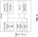
- Each of the one or more gNBs 160 may include one or more transceivers 176, one or more demodulators 172, one or more decoders 166, one or more encoders 109, one or more modulators 113, a data buffer 162 and a gNB operations module 182.
- one or more reception and/or transmission paths may be implemented in a gNB 160.
- only a single transceiver 176, decoder 166, demodulator 172, encoder 109 and modulator 113 are illustrated in the gNB 160, though multiple parallel elements (e.g., transceivers 176, decoders 166, demodulators 172, encoders 109 and modulators 113) may be implemented.
- the transceiver 176 may include one or more receivers 178 and one or more transmitters 117.
- the one or more receivers 178 may receive signals from the UE 102 using one or more physical antennas 180a-n.
- the receiver 178 may receive and downconvert signals to produce one or more received signals 174.
- the one or more received signals 174 may be provided to a demodulator 172.
- the one or more transmitters 117 may transmit signals to the UE 102 using one or more physical antennas 180a-n.
- the one or more transmitters 117 may upconvert and transmit one or more modulated signals 115.
- the demodulator 172 may demodulate the one or more received signals 174 to produce one or more demodulated signals 170.
- the one or more demodulated signals 170 may be provided to the decoder 166.
- the gNB 160 may use the decoder 166 to decode signals.
- the decoder 166 may produce one or more decoded signals 164, 168.
- a first eNB-decoded signal 164 may comprise received payload data, which may be stored in a data buffer 162.
- a second eNB-decoded signal 168 may comprise overhead data and/or control data.
- the second eNB-decoded signal 168 may provide data (e.g., PDSCH HARQ-ACK information) that may be used by the gNB operations module 182 to perform one or more operations.
- the gNB operations module 182 may enable the gNB 160 to communicate with the one or more UEs 102.
- the gNB operations module 182 may include one or more of a gNB scheduling module 194.
- the gNB scheduling module 194 may perform scheduling of downlink and/or uplink transmissions as described herein.
- the gNB operations module 182 may provide information 188 to the demodulator 172. For example, the gNB operations module 182 may inform the demodulator 172 of a modulation pattern anticipated for transmissions from the UE(s) 102.
- the gNB operations module 182 may provide information 186 to the decoder 166. For example, the gNB operations module 182 may inform the decoder 166 of an anticipated encoding for transmissions from the UE(s) 102.
- the gNB operations module 182 may provide information 101 to the encoder 109.
- the information 101 may include data to be encoded and/or instructions for encoding.
- the gNB operations module 182 may instruct the encoder 109 to encode information 101, including transmission data 105.
- the encoder 109 may encode transmission data 105 and/or other information included in the information 101 provided by the gNB operations module 182. For example, encoding the data 105 and/or other information included in the information 101 may involve error detection and/or correction coding, mapping data to space, time and/or frequency resources for transmission, multiplexing, etc.
- the encoder 109 may provide encoded data 111 to the modulator 113.
- the transmission data 105 may include network data to be relayed to the UE 102.
- the gNB operations module 182 may provide information 103 to the modulator 113.
- This information 103 may include instructions for the modulator 113.
- the gNB operations module 182 may inform the modulator 113 of a modulation type (e.g., constellation mapping) to be used for transmissions to the UE(s) 102.
- the modulator 113 may modulate the encoded data 111 to provide one or more modulated signals 115 to the one or more transmitters 117.
- the gNB operations module 182 may provide information 192 to the one or more transmitters 117.
- This information 192 may include instructions for the one or more transmitters 117.
- the gNB operations module 182 may instruct the one or more transmitters 117 when to (or when not to) transmit a signal to the UE(s) 102.
- the one or more transmitters 117 may upconvert and transmit the modulated signal(s) 115 to one or more UEs 102.
- a DL subframe may be transmitted from the gNB 160 to one or more UEs 102 and that a UL subframe may be transmitted from one or more UEs 102 to the gNB 160. Furthermore, both the gNB 160 and the one or more UEs 102 may transmit data in a standard special subframe.
- one or more of the elements or parts thereof included in the eNB(s) 160 and UE(s) 102 may be implemented in hardware.
- one or more of these elements or parts thereof may be implemented as a chip, circuitry or hardware components, etc.
- one or more of the functions or methods described herein may be implemented in and/or performed using hardware.
- one or more of the methods described herein may be implemented in and/or realized using a chipset, an application-specific integrated circuit (ASIC), a large-scale integrated circuit (LSI) or integrated circuit, etc.
- ASIC application-specific integrated circuit
- LSI large-scale integrated circuit
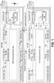
- Figure 2 shows examples of multiple numerologies 201.
- multiple numerologies 201 e.g., multiple subcarrier spacing
- ⁇ e.g., a subcarrier space configuration
- a cyclic prefix e.g., the ⁇ and the cyclic prefix for a carrier bandwidth part
- 15 kHz may be a reference numerology 201.
- an RE of the reference numerology 201 may be defined with a subcarrier spacing of 15 kHz in a frequency domain and 2048Ts + CP length (e.g., 160Ts or 144Ts) in a time domain, where Ts denotes a baseband sampling time unit defined as 1/(15000*2048) seconds.
- one subframe 369 may include N symbol subframe , ⁇ symbols 387. Additionally or alternatively, a resource block 391 may include a number of resource elements (RE) 389.
- the OFDM access scheme with cyclic prefix (CP) may be employed, which may be also referred to as CP-OFDM.
- a downlink radio frame may include multiple pairs of downlink resource blocks (RBs) 391 which are also referred to as physical resource blocks (PRBs).
- the downlink RB pair is a unit for assigning downlink radio resources, defined by a predetermined bandwidth (RB bandwidth) and a time slot.
- the downlink RB pair may include two downlink RBs 391 that are continuous in the time domain.
- an uplink radio frame may include multiple pairs of uplink resource blocks 391.
- the uplink RB pair is a unit for assigning uplink radio resources, defined by a predetermined bandwidth (RB bandwidth) and a time slot.
- the uplink RB pair may include two uplink RBs 391 that are continuous in the time domain.
- the uplink RB may include twelve sub-carriers in frequency domain and seven (for normal CP) or six (for extended CP) OFDM/DFT-S-OFDM symbols in time domain.
- a region defined by one sub-carrier in the frequency domain and one OFDM/DFT-S-OFDM symbol in the time domain is referred to as a resource element (RE) 389 and is uniquely identified by the index pair (k,l) in a slot, where k and l are indices in the frequency and time domains, respectively.
- RE resource element
- the resource element (k,l) 389 on the antenna port p and the subcarrier spacing configuration ⁇ is denoted (k,l)p, ⁇ .
- the physical resource blocks 391 are numbered from 0 to N RB ⁇ ⁇ 1 in the frequency domain.
- the following reference signals may be defined:
- NZP CSI-RS may be used for channel tracking (e.g., synchronization), measurement to obtain CSI (CSI measurement including channel measurement and interference measurement), and/or measurement to obtain the beam forming performance.
- NZP CSI-RS may be transmitted in the downlink (gNB to UE).
- NZP CSI-RS may be transmitted in an aperiodic or semi-persistent or periodic manner. Additionally, the NZP CSI-RS can be used for radio resource management (RRM) measurement and radio link control (RLM) measurement.
- RRM radio resource management
- RLM radio link control
- the SRS may be used for channel sounding and beam management.
- the SRS may be transmitted in the uplink (UE to gNB).
- the DCI may be used.
- the following DCI formats may be defined:
- DCI format 1_0 may be used for the scheduling of PUSCH in one cell.
- the DCI may be transmitted by means of the DCI format 0_0 with cyclic redundancy check (CRC) scrambled by Cell Radio Network Temporary Identifiers (C-RNTI) or Configured Scheduling RNTI (CS-RNTI) or Modulation and Coding Scheme - Cell RNTI (MCS-C-RNTI).
- CRC cyclic redundancy check
- C-RNTI Cell Radio Network Temporary Identifiers
- CS-RNTI Configured Scheduling RNTI
- MCS-C-RNTI Modulation and Coding Scheme - Cell RNTI
- DCI format 0_2 may be used for the scheduling of PUSCH in one cell.
- the DCI may be transmitted by means of the DCI format 0_2 with CRC scrambled by C-RNTI or CS-RNTI or SP-CSI-RNTI or MCS-C-RNTI.
- the DCI format 0_2 may be used for scheduling of PUSCH with high priority and/or low latency (e.g., URLLC).
- the DCI format 0_2 may be used for CSI request (e.g., aperiodic CSI reporting or semi-persistent CSI request).
- the DCI format 0_2 may be used for SRS request (e.g., aperiodic SRS transmission).
- DCI format 2_1 may be used for notifying the physical resource block(s) (PRB(s)) and orthogonal frequency division multiplexing (OFDM) symbol(s) where the UE may assume no transmission is intended for the UE.
- the DCI is transmitted by means of the DCI format 2_1 with CRC scrambled by interrupted transmission RNTI (INT-RNTI).
- INT-RNTI interrupted transmission RNTI
- the UE 102 may monitor one or more DCI formats on common search space set (CSS) and/or UE-specific search space set (USS).
- a set of PDCCH candidates for a UE to monitor may be defined in terms of PDCCH search space sets.
- a search space set can be a CSS set or a USS set.
- a UE 102 monitors PDCCH candidates in one or more of the following search spaces sets.
- the search space may be defined by a PDCCH configuration in a RRC layer.
- a Type0-PDCCH CSS set may be configured by pdcch-ConfigSIB 1 in MIB or by searchSpaceSIB1 in PDCCH-ConfigCommon or by searchSpaceZero in PDCCH-ConfigCommon for a DCI format with CRC scrambled by a SI-RNTI on the primary cell of the MCG
- a Type2-PDCCH CSS set may be configured by pagingSearchSpace in PDCCH-ConfigCommon for a DCI format with CRC scrambled by a P-RNTI on the primary cell of the MCG
- the UE 102 may monitor a set of candidates of the PDCCH in one or more control resource sets (e.g., CORESETs) on the active DL bandwidth part (BWP) on each activated serving cell according to corresponding search space sets.
- CORESETs may be configured from gNB 160 to a UE 102, and the CSS set(s) and the USS set(s) are defined in the configured CORESET.
- One or more CORESET may be configured in a RRC layer.
- the CORESET is, in the frequency domain and/or the time domain, a set 401 of PRBs 491 within which the UE 102 attempts to decode the DCI (e.g., the DCI format(s), the PDCCH(s)), where the PRBs 491 may or may not be frequency contiguous and/or time contiguous, a UE 102 may be configured with one or more control resource sets (e.g., the CORESETs) and one DCI message may be mapped within one control resource set.
- a PRB 491 is the resource unit size (which may or may not include DM-RS) for the DL control channel.
- Figure 5 illustrates an example of beamforming and quasi-colocation (QCL) type.
- the gNB 560 and UE 502 may perform beamforming by having multiple antenna elements.
- the beamforming is operated by using a directional antenna(s) or applying phase shift for each antenna element (e.g., a high electric field strength to a certain spatial direction can be achieved).
- the beamforming or beam may be rephrased by "spatial domain transmission filter” or "spatial domain filter.”
- the gNB 560 may apply the transmission beamforming and transmit the DL channels and/or DL signals and a UE 502 may also apply the reception beamforming and receive the DL channels and/or DL signals.
- a UE 560 may apply the transmission beamforming and transmit the UL channels and/or UL signals and a gNB 560 may also apply the reception beamforming and receive the UL channels and/or UL signals.
- the beam correspondence may be defined according to the UE capability. In some examples, the beam correspondence may be defined in accordance with the following.
- a UE 502 can decide the transmission beamforming for UL channels and/or UL signals from the reception beamforming for DL channels and/or DL signals.
- a gNB 560 can decide the transmission beamforming for DL channels and/or DL signals from the reception beamforming for UL channels and/or UL signals.
- NZP-CSI-RS(s) and SRS(s) may be used to measure the channel quality in the downlink and uplink, respectively.
- gNB 560 may transmit one or more NZP CSI-RSs.
- the UE 502 may measure the one or more NZP CSI-RSs.
- the UE 502 may change the beamforming to receive each NZP CSI-RS.
- the UE 502 can identify which combination of transmission beamforming at gNB side corresponding to NZP CSI-RS corresponding and the reception beamforming at the UE side.
- a UE 502 may transmit one or more SRSs.
- the gNB 502 measure the one or more SRSs.
- the gNB 560 may change the reception beamforming to receive each SRS.
- the gNB 560 can identify which combination of transmission beamforming at gNB side corresponding to SRS corresponding and the reception beamforming at the gNB side.
- the quasi-colocation (QCL) assumption may be defined.
- Two antenna ports are said to be quasi co-located if the large-scale properties of the channel over which a symbol on one antenna port is conveyed can be inferred from the channel over which a symbol on the other antenna port is conveyed.
- the large-scale properties include one or more of delay spread, Doppler spread, Doppler shift, average gain, average delay, and spatial Rx parameters.
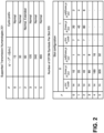
- QCL types may be defined:
- a gNB 560 may configure transmission configuration indication (TCI) states to a UE 502.
- TCI state may include the following:
- a TCI state includes QCL type D and NZP CSI-RS #1 and indicated to the UE 502
- the UE 502 may apply Rx beam #1 to the reception of a PDCCH, a PDSCH, and/or DL signal(s).
- a UE 502 can determine the reception beam by using TCI states for reception of PDCCH, PDSCH, and/or DL signals.
- N TCI states may be configured by a RRC message.
- a gNB 560 may indicate one of the configured TCI states by DCI (e.g., DCI format 1_1 or DCI format 1_2).
- the gNB 560 may indicate one of the configured TCI by MAC CE.
- the MAC CE selects more than one TCI states from the configured TCI states and DCI indicates one of the more than one TCI states activated by MAC CE.
- the UE may receive 702 first information to configure one or more CSI-RS for tracking and second information to configure time domain correlation related information. In some examples, this may be performed as described in relation to Figure 1 .
- the UE may transmit 704 a CSI report including the time domain correlation related information.
- a first parameter trs-Info may be included in the first information.
- a second parameter reportQuantity may not be set to 'none'.
- the time domain correlation related information may be measured by the one or more CSI-RS for tracking. In some examples, this may be performed as described in relation to Figure 1 .
- Figure 8 is a flow diagram illustrating an example of a method 800 in accordance with some of the techniques described herein.
- the method 800 may be performed by the gNB 160 described in relation to Figure 1 .
- the gNB may transmit 802 first information to configure one or more CSI-RS for tracking and second information to configure time domain correlation related information. In some examples, this may be performed as described in relation to Figure 1 .
- the gNB may receive 804 a CSI report including the time domain correlation related information.
- a first parameter trs-Info may be included in the first information.
- a second parameter reportQuantity may not be set to 'none'.
- the time domain correlation related information may be measured by the one or more CSI-RS for tracking. In some examples, this may be performed as described in relation to Figure 1 .
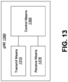
- Figure 9B is a flow diagram illustrating an example of a method 900b in accordance with some of the techniques described herein.
- the method 900b may be performed by the gNB 160 described in relation to Figure 1 .
- the gNB may transmit 902b first information to configure one or more CSI-RS for tracking and second information to configure time domain correlation related information. In some examples, this may be performed as described in relation to Figure 1 .
- Instructions 1007b and/or data 1009b loaded into the processor 1003 may also include instructions 1007a and/or data 1009a from memory 1005 that were loaded for execution or processing by the processor 1003.
- the instructions 1007b may be executed by the processor 1003 to implement the methods described herein.
- Instructions 1107b and/or data 1109b loaded into the processor 1103 may also include instructions 1107a and/or data 1109a from memory 1105 that were loaded for execution or processing by the processor 1103.
- the instructions 1107b may be executed by the processor 1103 to implement the methods described herein.
Landscapes
- Engineering & Computer Science (AREA)
- Signal Processing (AREA)
- Computer Networks & Wireless Communication (AREA)
- Quality & Reliability (AREA)
- Mobile Radio Communication Systems (AREA)
Applications Claiming Priority (1)
| Application Number | Priority Date | Filing Date | Title |
|---|---|---|---|
| US17/589,628 US12225569B2 (en) | 2022-01-31 | 2022-01-31 | User equipments, base stations and methods for time domain correlation information reporting |
Publications (2)
| Publication Number | Publication Date |
|---|---|
| EP4221038A1 EP4221038A1 (en) | 2023-08-02 |
| EP4221038B1 true EP4221038B1 (en) | 2025-07-09 |
Family
ID=80735438
Family Applications (1)
| Application Number | Title | Priority Date | Filing Date |
|---|---|---|---|
| EP22161331.8A Active EP4221038B1 (en) | 2022-01-31 | 2022-03-10 | User equipments, base stations and methods for time domain correlation information reporting |
Country Status (4)
| Country | Link |
|---|---|
| US (1) | US12225569B2 (https=) |
| EP (1) | EP4221038B1 (https=) |
| JP (1) | JP7728719B2 (https=) |
| CN (1) | CN116566411A (https=) |
Family Cites Families (8)
| Publication number | Priority date | Publication date | Assignee | Title |
|---|---|---|---|---|
| US10484064B2 (en) * | 2016-09-01 | 2019-11-19 | Samsung Electronics Co., Ltd. | Method and apparatus for downlink and uplink CSI acquisition |
| ES2908256T3 (es) | 2017-11-17 | 2022-04-28 | Ericsson Telefon Ab L M | Técnica para configurar una señal de referencia de seguimiento de fase |
| US10863494B2 (en) * | 2018-01-22 | 2020-12-08 | Apple Inc. | Control signaling for uplink multiple input multiple output, channel state information reference signal configuration and sounding reference signal configuration |
| SG11202008747RA (en) | 2018-04-04 | 2020-10-29 | Guangdong Oppo Mobile Telecommunications Corp Ltd | Method and device for information determination and configuration, and computer storage medium |
| WO2020091543A1 (ko) | 2018-11-02 | 2020-05-07 | 엘지전자 주식회사 | 무선 통신 시스템에서 채널 상태 정보를 보고하기 위한 방법 및 이를 위한 장치 |
| KR102911053B1 (ko) | 2020-05-06 | 2026-01-12 | 삼성전자주식회사 | 무선통신 시스템에서 채널 상태 보고 방법 및 장치 |
| US11722353B2 (en) * | 2020-10-09 | 2023-08-08 | Samsung Electronics Co., Ltd. | Enhancements to support HST-SFN deployment scenario |
| US20230246687A1 (en) * | 2022-01-28 | 2023-08-03 | Samsung Electronics Co., Ltd. | Method and apparatus for reporting of time-domain channel properties |
-
2022
- 2022-01-31 US US17/589,628 patent/US12225569B2/en active Active
- 2022-03-10 EP EP22161331.8A patent/EP4221038B1/en active Active
- 2022-03-10 CN CN202210234172.XA patent/CN116566411A/zh active Pending
- 2022-03-11 JP JP2022038298A patent/JP7728719B2/ja active Active
Also Published As
| Publication number | Publication date |
|---|---|
| US12225569B2 (en) | 2025-02-11 |
| JP2023111797A (ja) | 2023-08-10 |
| JP7728719B2 (ja) | 2025-08-25 |
| EP4221038A1 (en) | 2023-08-02 |
| CN116566411A (zh) | 2023-08-08 |
| US20230247661A1 (en) | 2023-08-03 |
Similar Documents
| Publication | Publication Date | Title |
|---|---|---|
| US10334576B2 (en) | Systems and methods for uplink control information reporting with license-assisted access (LAA) uplink transmissions | |
| US12267830B2 (en) | User equipments, base stations and methods for transmission configuration indication for PDSCH | |
| US20230388076A1 (en) | User equipments, base stations and methods for multi-panel pusch transmission | |
| US12335192B2 (en) | User equipments, base stations and methods for multi-beam SRS transmission | |
| US20230389040A1 (en) | User equipments, base stations and methods for joint beam management | |
| WO2023171230A1 (en) | User equipments, base stations and methods for beam indication with extended tci framework for pdsch | |
| US20230300830A1 (en) | Terminal device, base station and method performed by terminal device | |
| US12495427B2 (en) | User equipments, base stations and methods for multi-panel/TRP PDCCH transmission and reception | |
| US20230171064A1 (en) | User equipments, base stations and methods for downlink ptrs transmission | |
| US20230198707A1 (en) | User equipments, base stations and methods for uplink ptrs transmission | |
| US20230171063A1 (en) | User equipments, base stations and methods for multi-beam/panel pusch transmission | |
| EP4221037A1 (en) | User equipments, base stations and methods for time domain correlation information signaling | |
| US12432736B2 (en) | User equipments, base stations and methods for multi-beam/panel PUCCH transmission | |
| US20250119263A1 (en) | User equipments, base stations and methods for beam indication with inter-cell mobility for pdsch | |
| EP4221038B1 (en) | User equipments, base stations and methods for time domain correlation information reporting | |
| US12464518B2 (en) | User equipments, base stations and methods for multi-panel PUSCH transmission | |
| US20240155638A1 (en) | User equipments, base stations, and methods for multi-beam srs transmission | |
| WO2022239541A1 (en) | User equipments, base stations, and methods for srs transmission and transmission power control | |
| US20230308152A1 (en) | User equipments, base stations and methods for csi reporting for ai/ml | |
| US20230308151A1 (en) | User equipments, base stations and methods for csi reporting for ai/ml |
Legal Events
| Date | Code | Title | Description |
|---|---|---|---|
| PUAI | Public reference made under article 153(3) epc to a published international application that has entered the european phase |
Free format text: ORIGINAL CODE: 0009012 |
|
| STAA | Information on the status of an ep patent application or granted ep patent |
Free format text: STATUS: THE APPLICATION HAS BEEN PUBLISHED |
|
| AK | Designated contracting states |
Kind code of ref document: A1 Designated state(s): AL AT BE BG CH CY CZ DE DK EE ES FI FR GB GR HR HU IE IS IT LI LT LU LV MC MK MT NL NO PL PT RO RS SE SI SK SM TR |
|
| STAA | Information on the status of an ep patent application or granted ep patent |
Free format text: STATUS: REQUEST FOR EXAMINATION WAS MADE |
|
| 17P | Request for examination filed |
Effective date: 20240202 |
|
| RBV | Designated contracting states (corrected) |
Designated state(s): AL AT BE BG CH CY CZ DE DK EE ES FI FR GB GR HR HU IE IS IT LI LT LU LV MC MK MT NL NO PL PT RO RS SE SI SK SM TR |
|
| GRAP | Despatch of communication of intention to grant a patent |
Free format text: ORIGINAL CODE: EPIDOSNIGR1 |
|
| STAA | Information on the status of an ep patent application or granted ep patent |
Free format text: STATUS: GRANT OF PATENT IS INTENDED |
|
| INTG | Intention to grant announced |
Effective date: 20250219 |
|
| GRAS | Grant fee paid |
Free format text: ORIGINAL CODE: EPIDOSNIGR3 |
|
| GRAA | (expected) grant |
Free format text: ORIGINAL CODE: 0009210 |
|
| STAA | Information on the status of an ep patent application or granted ep patent |
Free format text: STATUS: THE PATENT HAS BEEN GRANTED |
|
| AK | Designated contracting states |
Kind code of ref document: B1 Designated state(s): AL AT BE BG CH CY CZ DE DK EE ES FI FR GB GR HR HU IE IS IT LI LT LU LV MC MK MT NL NO PL PT RO RS SE SI SK SM TR |
|
| REG | Reference to a national code |
Ref country code: GB Ref legal event code: FG4D |
|
| REG | Reference to a national code |
Ref country code: CH Ref legal event code: EP |
|
| REG | Reference to a national code |
Ref country code: IE Ref legal event code: FG4D |
|
| REG | Reference to a national code |
Ref country code: DE Ref legal event code: R096 Ref document number: 602022017160 Country of ref document: DE |
|
| REG | Reference to a national code |
Ref country code: NL Ref legal event code: MP Effective date: 20250709 |
|
| PG25 | Lapsed in a contracting state [announced via postgrant information from national office to epo] |
Ref country code: PT Free format text: LAPSE BECAUSE OF FAILURE TO SUBMIT A TRANSLATION OF THE DESCRIPTION OR TO PAY THE FEE WITHIN THE PRESCRIBED TIME-LIMIT Effective date: 20251110 |
|
| PG25 | Lapsed in a contracting state [announced via postgrant information from national office to epo] |
Ref country code: NL Free format text: LAPSE BECAUSE OF FAILURE TO SUBMIT A TRANSLATION OF THE DESCRIPTION OR TO PAY THE FEE WITHIN THE PRESCRIBED TIME-LIMIT Effective date: 20250709 |
|
| REG | Reference to a national code |
Ref country code: AT Ref legal event code: MK05 Ref document number: 1812884 Country of ref document: AT Kind code of ref document: T Effective date: 20250709 |
|
| PG25 | Lapsed in a contracting state [announced via postgrant information from national office to epo] |
Ref country code: IS Free format text: LAPSE BECAUSE OF FAILURE TO SUBMIT A TRANSLATION OF THE DESCRIPTION OR TO PAY THE FEE WITHIN THE PRESCRIBED TIME-LIMIT Effective date: 20251109 |
|
| PG25 | Lapsed in a contracting state [announced via postgrant information from national office to epo] |
Ref country code: NO Free format text: LAPSE BECAUSE OF FAILURE TO SUBMIT A TRANSLATION OF THE DESCRIPTION OR TO PAY THE FEE WITHIN THE PRESCRIBED TIME-LIMIT Effective date: 20251009 |
|
| REG | Reference to a national code |
Ref country code: LT Ref legal event code: MG9D |
|
| PG25 | Lapsed in a contracting state [announced via postgrant information from national office to epo] |
Ref country code: AT Free format text: LAPSE BECAUSE OF FAILURE TO SUBMIT A TRANSLATION OF THE DESCRIPTION OR TO PAY THE FEE WITHIN THE PRESCRIBED TIME-LIMIT Effective date: 20250709 |
|
| PG25 | Lapsed in a contracting state [announced via postgrant information from national office to epo] |
Ref country code: FI Free format text: LAPSE BECAUSE OF FAILURE TO SUBMIT A TRANSLATION OF THE DESCRIPTION OR TO PAY THE FEE WITHIN THE PRESCRIBED TIME-LIMIT Effective date: 20250709 |
|
| PG25 | Lapsed in a contracting state [announced via postgrant information from national office to epo] |
Ref country code: HR Free format text: LAPSE BECAUSE OF FAILURE TO SUBMIT A TRANSLATION OF THE DESCRIPTION OR TO PAY THE FEE WITHIN THE PRESCRIBED TIME-LIMIT Effective date: 20250709 |
|
| PG25 | Lapsed in a contracting state [announced via postgrant information from national office to epo] |
Ref country code: GR Free format text: LAPSE BECAUSE OF FAILURE TO SUBMIT A TRANSLATION OF THE DESCRIPTION OR TO PAY THE FEE WITHIN THE PRESCRIBED TIME-LIMIT Effective date: 20251010 |
|
| PG25 | Lapsed in a contracting state [announced via postgrant information from national office to epo] |
Ref country code: SE Free format text: LAPSE BECAUSE OF FAILURE TO SUBMIT A TRANSLATION OF THE DESCRIPTION OR TO PAY THE FEE WITHIN THE PRESCRIBED TIME-LIMIT Effective date: 20250709 |
|
| PG25 | Lapsed in a contracting state [announced via postgrant information from national office to epo] |
Ref country code: LV Free format text: LAPSE BECAUSE OF FAILURE TO SUBMIT A TRANSLATION OF THE DESCRIPTION OR TO PAY THE FEE WITHIN THE PRESCRIBED TIME-LIMIT Effective date: 20250709 |
|
| PG25 | Lapsed in a contracting state [announced via postgrant information from national office to epo] |
Ref country code: BG Free format text: LAPSE BECAUSE OF FAILURE TO SUBMIT A TRANSLATION OF THE DESCRIPTION OR TO PAY THE FEE WITHIN THE PRESCRIBED TIME-LIMIT Effective date: 20250709 Ref country code: PL Free format text: LAPSE BECAUSE OF FAILURE TO SUBMIT A TRANSLATION OF THE DESCRIPTION OR TO PAY THE FEE WITHIN THE PRESCRIBED TIME-LIMIT Effective date: 20250709 |
|
| PG25 | Lapsed in a contracting state [announced via postgrant information from national office to epo] |
Ref country code: RS Free format text: LAPSE BECAUSE OF FAILURE TO SUBMIT A TRANSLATION OF THE DESCRIPTION OR TO PAY THE FEE WITHIN THE PRESCRIBED TIME-LIMIT Effective date: 20251009 |
|
| PG25 | Lapsed in a contracting state [announced via postgrant information from national office to epo] |
Ref country code: ES Free format text: LAPSE BECAUSE OF FAILURE TO SUBMIT A TRANSLATION OF THE DESCRIPTION OR TO PAY THE FEE WITHIN THE PRESCRIBED TIME-LIMIT Effective date: 20250709 |
|
| PG25 | Lapsed in a contracting state [announced via postgrant information from national office to epo] |
Ref country code: SM Free format text: LAPSE BECAUSE OF FAILURE TO SUBMIT A TRANSLATION OF THE DESCRIPTION OR TO PAY THE FEE WITHIN THE PRESCRIBED TIME-LIMIT Effective date: 20250709 |
|
| PGFP | Annual fee paid to national office [announced via postgrant information from national office to epo] |
Ref country code: GB Payment date: 20260324 Year of fee payment: 5 |
|
| PG25 | Lapsed in a contracting state [announced via postgrant information from national office to epo] |
Ref country code: DK Free format text: LAPSE BECAUSE OF FAILURE TO SUBMIT A TRANSLATION OF THE DESCRIPTION OR TO PAY THE FEE WITHIN THE PRESCRIBED TIME-LIMIT Effective date: 20250709 |
|
| PGFP | Annual fee paid to national office [announced via postgrant information from national office to epo] |
Ref country code: DE Payment date: 20260319 Year of fee payment: 5 |
|
| PG25 | Lapsed in a contracting state [announced via postgrant information from national office to epo] |
Ref country code: IT Free format text: LAPSE BECAUSE OF FAILURE TO SUBMIT A TRANSLATION OF THE DESCRIPTION OR TO PAY THE FEE WITHIN THE PRESCRIBED TIME-LIMIT Effective date: 20250709 |
|
| PGFP | Annual fee paid to national office [announced via postgrant information from national office to epo] |
Ref country code: FR Payment date: 20260323 Year of fee payment: 5 |
|
| PG25 | Lapsed in a contracting state [announced via postgrant information from national office to epo] |
Ref country code: CZ Free format text: LAPSE BECAUSE OF FAILURE TO SUBMIT A TRANSLATION OF THE DESCRIPTION OR TO PAY THE FEE WITHIN THE PRESCRIBED TIME-LIMIT Effective date: 20250709 |
|
| PG25 | Lapsed in a contracting state [announced via postgrant information from national office to epo] |
Ref country code: SK Free format text: LAPSE BECAUSE OF FAILURE TO SUBMIT A TRANSLATION OF THE DESCRIPTION OR TO PAY THE FEE WITHIN THE PRESCRIBED TIME-LIMIT Effective date: 20250709 Ref country code: EE Free format text: LAPSE BECAUSE OF FAILURE TO SUBMIT A TRANSLATION OF THE DESCRIPTION OR TO PAY THE FEE WITHIN THE PRESCRIBED TIME-LIMIT Effective date: 20250709 |