EP4220868A1 - Power adapter - Google Patents
Power adapter Download PDFInfo
- Publication number
- EP4220868A1 EP4220868A1 EP21884602.0A EP21884602A EP4220868A1 EP 4220868 A1 EP4220868 A1 EP 4220868A1 EP 21884602 A EP21884602 A EP 21884602A EP 4220868 A1 EP4220868 A1 EP 4220868A1
- Authority
- EP
- European Patent Office
- Prior art keywords
- housing
- component
- connector
- power adapter
- adapter according
- Prior art date
- Legal status (The legal status is an assumption and is not a legal conclusion. Google has not performed a legal analysis and makes no representation as to the accuracy of the status listed.)
- Pending
Links
Images





Classifications
-
- H—ELECTRICITY
- H01—ELECTRIC ELEMENTS
- H01R—ELECTRICALLY-CONDUCTIVE CONNECTIONS; STRUCTURAL ASSOCIATIONS OF A PLURALITY OF MUTUALLY-INSULATED ELECTRICAL CONNECTING ELEMENTS; COUPLING DEVICES; CURRENT COLLECTORS
- H01R24/00—Two-part coupling devices, or either of their cooperating parts, characterised by their overall structure
- H01R24/66—Two-part coupling devices, or either of their cooperating parts, characterised by their overall structure with pins, blades or analogous contacts and secured to apparatus or structure, e.g. to a wall
- H01R24/68—Two-part coupling devices, or either of their cooperating parts, characterised by their overall structure with pins, blades or analogous contacts and secured to apparatus or structure, e.g. to a wall mounted on directly pluggable apparatus
-
- H—ELECTRICITY
- H01—ELECTRIC ELEMENTS
- H01R—ELECTRICALLY-CONDUCTIVE CONNECTIONS; STRUCTURAL ASSOCIATIONS OF A PLURALITY OF MUTUALLY-INSULATED ELECTRICAL CONNECTING ELEMENTS; COUPLING DEVICES; CURRENT COLLECTORS
- H01R13/00—Details of coupling devices of the kinds covered by groups H01R12/70 or H01R24/00 - H01R33/00
- H01R13/60—Means for supporting coupling part when not engaged
-
- H—ELECTRICITY
- H01—ELECTRIC ELEMENTS
- H01R—ELECTRICALLY-CONDUCTIVE CONNECTIONS; STRUCTURAL ASSOCIATIONS OF A PLURALITY OF MUTUALLY-INSULATED ELECTRICAL CONNECTING ELEMENTS; COUPLING DEVICES; CURRENT COLLECTORS
- H01R12/00—Structural associations of a plurality of mutually-insulated electrical connecting elements, specially adapted for printed circuits, e.g. printed circuit boards [PCB], flat or ribbon cables, or like generally planar structures, e.g. terminal strips, terminal blocks; Coupling devices specially adapted for printed circuits, flat or ribbon cables, or like generally planar structures; Terminals specially adapted for contact with, or insertion into, printed circuits, flat or ribbon cables, or like generally planar structures
- H01R12/70—Coupling devices
-
- H—ELECTRICITY
- H01—ELECTRIC ELEMENTS
- H01R—ELECTRICALLY-CONDUCTIVE CONNECTIONS; STRUCTURAL ASSOCIATIONS OF A PLURALITY OF MUTUALLY-INSULATED ELECTRICAL CONNECTING ELEMENTS; COUPLING DEVICES; CURRENT COLLECTORS
- H01R13/00—Details of coupling devices of the kinds covered by groups H01R12/70 or H01R24/00 - H01R33/00
- H01R13/02—Contact members
- H01R13/04—Pins or blades for co-operation with sockets
-
- H—ELECTRICITY
- H01—ELECTRIC ELEMENTS
- H01R—ELECTRICALLY-CONDUCTIVE CONNECTIONS; STRUCTURAL ASSOCIATIONS OF A PLURALITY OF MUTUALLY-INSULATED ELECTRICAL CONNECTING ELEMENTS; COUPLING DEVICES; CURRENT COLLECTORS
- H01R13/00—Details of coupling devices of the kinds covered by groups H01R12/70 or H01R24/00 - H01R33/00
- H01R13/46—Bases; Cases
- H01R13/502—Bases; Cases composed of different pieces
-
- H—ELECTRICITY
- H01—ELECTRIC ELEMENTS
- H01R—ELECTRICALLY-CONDUCTIVE CONNECTIONS; STRUCTURAL ASSOCIATIONS OF A PLURALITY OF MUTUALLY-INSULATED ELECTRICAL CONNECTING ELEMENTS; COUPLING DEVICES; CURRENT COLLECTORS
- H01R13/00—Details of coupling devices of the kinds covered by groups H01R12/70 or H01R24/00 - H01R33/00
- H01R13/44—Means for preventing access to live contacts
-
- H—ELECTRICITY
- H01—ELECTRIC ELEMENTS
- H01R—ELECTRICALLY-CONDUCTIVE CONNECTIONS; STRUCTURAL ASSOCIATIONS OF A PLURALITY OF MUTUALLY-INSULATED ELECTRICAL CONNECTING ELEMENTS; COUPLING DEVICES; CURRENT COLLECTORS
- H01R13/00—Details of coupling devices of the kinds covered by groups H01R12/70 or H01R24/00 - H01R33/00
- H01R13/46—Bases; Cases
- H01R13/502—Bases; Cases composed of different pieces
- H01R13/506—Bases; Cases composed of different pieces assembled by snap action of the parts
-
- H—ELECTRICITY
- H01—ELECTRIC ELEMENTS
- H01R—ELECTRICALLY-CONDUCTIVE CONNECTIONS; STRUCTURAL ASSOCIATIONS OF A PLURALITY OF MUTUALLY-INSULATED ELECTRICAL CONNECTING ELEMENTS; COUPLING DEVICES; CURRENT COLLECTORS
- H01R13/00—Details of coupling devices of the kinds covered by groups H01R12/70 or H01R24/00 - H01R33/00
- H01R13/66—Structural association with built-in electrical component
- H01R13/665—Structural association with built-in electrical component with built-in electronic circuit
- H01R13/6658—Structural association with built-in electrical component with built-in electronic circuit on printed circuit board
Definitions
- the present disclosure relates to the field of electronic devices, and in particular to a power adapter.
- a power adapter includes a first housing, a second housing, an ejector mechanism, and a first connector.
- the second housing is connected to the first housing.
- the first housing and the second housing cooperatively defines an accommodating cavity, and the first housing and the second housing are configured to be concentrically rotatable relative to each other.
- the ejector mechanism is fixedly connected to the first housing.
- the first connector is fixedly connected to the ejector mechanism.
- the ejector mechanism is configured to push or pull the first connector, and enable the first connector to be at least partially located inside the accommodating cavity or outside the accommodating cavity, in response to a relative rotation between the first housing and the second housing.
- a power adapter includes a first housing, a second housing, and a first connector.
- the first housing and the second housing are configured to be concentrically rotatable relative to each other.
- the first connector configured to be extended out of or retracted into the second housing in response to a relative rotation between the first housing and the second housing.
- a power adapter includes a first housing, a second housing, an electronic assembly, a first connector, an ejector mechanism, and a second connector.
- the first housing defines a first receiving cavity.
- the second housing defines a second receiving cavity and connected to the first housing.
- the first housing and the second housing are configured to be concentrically rotatable relative to each other.
- the electronic assembly includes a printed circuit board arranged in the first receiving cavity; and a conductive component, arranged in the second receiving cavity, and configured to be electrically connected to the printed circuit board.
- the first connector is arranged in the first receiving cavity and electrically connected to the printed circuit board.
- the ejector mechanism is arranged in the second receiving cavity and fixedly connected to the first housing.
- the second connector is mounted on the ejector mechanism.
- the ejector mechanism is configured to pushing or pulling the second connector and enable the second connector to be at least partially located inside the second receiving cavity or outside the second receiving cavity, in response to the relative rotation between the first housing and the second housing.
- the second connector is configured to be located outside the second receiving cavity in response to the conductive component being conducted to the second connector, and the conductive component is configured to be disconnected from the second connector in response to the second connector being located inside the second receiving cavity.
- the power adapter provided in some embodiments of the present disclosure includes the first housing and the second housing configured to be concentrically rotatable relative to each other.
- the ejector mechanism is adjusted through the relative rotation between the first housing and the second housing to cause the first connector to displace.
- the first connector is at least partially located outside the accommodating cavity for normal usage or the first connector is located in the accommodating cavity for storage.
- Embodiment herein means that a particular feature, structure, or characteristic described with reference to embodiments may be included in at least one embodiment of the present disclosure.
- the terms appearing in various places in the specification are not necessarily shown in the same embodiment, and are not exclusive or alternative embodiments that are mutually exclusive with other embodiments. Those skilled in the art will understand explicitly and implicitly that the embodiments described herein may be combined with other embodiments.
- a power adapter is provided in some embodiments of the present disclosure.
- the power adapter is also called an external power supply, which is a power-supply-voltage convertor of a small portable electronic device and an electronic appliance.
- An operating principle of the power adapter is to convert an AC input to a DC output.
- Power adapters have a wall plug type and a desktop type in terms of connection manners.
- connection may indicates a fixedly connection, a detachable connection, or a one-piece connection; a mechanical connection or an electrical connection; a direct connection or an indirect connection through an intermediate medium thereof, or a fluid communication between insides of two components.
- Electronic devices covered in some embodiments of the present disclosure may include, but are not limited to, cell phones, tablet computers, wearable devices (e.g., watches, bracelets, augmented reality glasses, virtual reality glasses, etc.), smart appliances (e.g., table lamps, fans, light bars, etc.), other audio products (e.g., speakers, storytellers, headphones, etc.), security cameras, set-top boxes, routers, or massage devices.
- wearable devices e.g., watches, bracelets, augmented reality glasses, virtual reality glasses, etc.
- smart appliances e.g., table lamps, fans, light bars, etc.
- other audio products e.g., speakers, storytellers, headphones, etc.
- security cameras set-top boxes, routers, or massage devices.
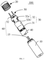
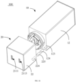
- FIG. 1 is a structural schematic view of a power adapter according to an embodiment of the present disclosure
- FIG. 2 is a structural schematic view of the power adapter in FIG. 1 from another perspective
- FIG. 3 is an exploded view of the power adapter in FIG. 1
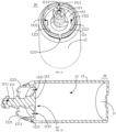
- FIG. 4 is a cross-sectional view of the power adapter in FIG. 1 along a line IV-IV in FIG. 1 .
- the power adapter 100 may include a first housing 10, a second housing 20 engaged with the first housing 10, an electronic assembly 30 disposed in the first housing 10 and the second housing 20, a first connector 40 disposed in the first housing 10, a second connector 50 capable of being extending out of or retracting into the second housing 20, and an ejector mechanism 60 received in the first housing 10 and the second housing 20 and configured to drive the second connector 50 to be extended out of or retracted into the second housing 20.
- the first housing 10 may be engaged with the second housing 20 to form a housing.
- An accommodating cavity 101 is defined in the housing and configured to accommodate and protect components (such as a printed circuit board, and a transformer, an inductor, a capacitor, a control integrated circuit on the printed circuit board, etc.) in the power adapter 100.
- the first housing 10 is rotatable around an axis relative to the second housing 20, and the second housing 20 is also rotatable around the same axis relative to the first housing 10.
- the electronic assembly 30 is arranged in the accommodating cavity 101 and configured to realize a current conversion or a voltage conversion. For example, the electronic assembly 30 is configured to convert the AC input to the DC output.
- the first connector 40 and the second connector 50 are electrically connected to the electronic assembly 30, respectively.
- the second connector 50 is at least partially located inside the accommodating cavity 101 or outside the accommodating cavity 101, in response to a relative rotation between the first housing 10 and the second housing 20.
- One of the first connector 40 and the second connector 50 is configured to be connected to an AC power source (e.g., 110-220 VAC) to allow the power adapter 100 to receive an AC from the AC power source.
- the other one of the first connector 40 and the second connector 50 is configured to be connected to an electronic device to allow the power adapter 100 to serve as a DC power source (e.g., 5-24 VDC) to output a DC to the electronic device.
- a DC power source e.g., 5-24 VDC
- the first connector 40 may be configured in the same manner as the second connector 50, such that the first connector 40 is at least partially located inside the accommodating cavity 101 or outside the accommodating cavity 101 in response to the relative rotation between the first housing 10 and the second housing 20.
- the number of the connectors may be one.
- the first connector 40 may be omitted, and the electronic assembly 30 is connected to the AC power source (e.g., 110-220 VAC) through the second connector 50, such that the power adapter 100 receives the AC from the AC power source.
- the electronic assembly 30 is directly connected to the electronic device rather than connected to the electronic device through the first connector 40. That is, the power adapter 100 is a part of the electronic device.
- the number of the connectors such as the first connector 40 and the second connector 50, may be at least two.
- the number of the first connector 40 is two, and two electronic devices may be connected through the first connector 40.
- first housing may also be referred to as “second housing”.
- first connector can also be referred to as “second connector”.
- FIG. 5 is a structural schematic view of a first housing 10 shown in FIG. 3
- FIG. 6 is a structural schematic view of the first housing 10 in FIG. 5 from another perspective
- FIG. 7 is a cross-sectional view of the first housing 10 in FIG. 5 .
- the first housing 10 may be made of any suitable material, e.g., plastic, rubber, ceramic, silicon, etc.
- the first housing 10 is shown as a cylindrical shape, however, the shape of the first housing 10 is not limited thereto.
- the first housing 10 may have any of other shapes required for a particular application.
- the first housing 10 may have one of a rectangular shape, a spherical shape, an irregular shape, etc.
- the first housing 10 may include a first bottom plate 11 and a first side plate 12 surrounding or enclosing the first bottom plate 11.
- the first side plate 12 is connected to the first bottom plate 11 to form the first housing 10 with a first receiving cavity 13 inside.
- the first receiving cavity 13 of the first housing 10 may be configured to receive components in the power adapter 100 such as a part or a whole of the electronic assembly 30 and the first connector 40.
- the first receiving cavity 13 of the first housing 10 may also be configured to only receive a portion of the first connector 40.
- the first housing cavity 13 may form a part of the accommodating cavity 101.
- the first receiving cavity 13 may also form the whole of the accommodating cavity 101.
- the first bottom plate 11 has a circular plate-like structure.
- the first bottom plate 11 may have other shapes, such as the rectangular shape, a polygonal shape, an irregular shape, etc., which may be changed according to actual situations.
- a through hole 111 may be defined in the first bottom plate 11, and the through hole 111 penetrates the first bottom plate 11.
- the through hole 111 is in communication with the first receiving cavity 13, and is configured to receive the first connector 40.
- the first connector 40 may be extended out of the first receiving cavity 13 via the through hole 111.
- the number of the through hole 111 may be at least one. Of course, the number of the through hole 111 may be determined based on the number of the first connector 40 and particular application requirements. In another embodiment, the through hole 111 may be omitted. In some embodiments, the through hole 111 may be replaced by a recess. For example, the recess is defined in the first bottom plate 11 to accommodate the first connector 40, such that the first connector 40 is located outside the first receiving cavity 13.
- the first side plate 12 may have a cylindrical tubular structure, which is not limited thereto. A shape of the first side plate 12 may be changed according to the actual situations, which is not repeated herein.
- the first side plate 12 extends from an edge of the first bottom plate 11 towards a side away from the first bottom plate 11, and a first opening 14 is defined accordingly.
- the first side plate 12 is engaged with the second housing 20 at a position where the first opening 14 is defined.
- the first side plate 12 and the first bottom plate 11 may be of an integral structure.
- the first side plate 12 may be glued to the first bottom plate 11 to form the first housing 10.
- the first side plate 12 may be fixed to the first bottom plate 11 to form the first housing 10 by means of threads or a buckle, such that the first bottom plate 11 is detachably connected to the first side plate 12.
- the through hole 111 may also be defined in the first side plate 12 when the first side plate 12 is connected to the first bottom plate 11 to form the first housing 10. That is, the through hole 111 may be defined in the first bottom plate 11 and/or the first side plate 12.
- the first housing 10 such as the first side plate 12, is provided with a first buckling member 121 at the position where the first opening 14 is defined, such that the first housing 10 is engaged with the second housing 20.
- the first buckling member 121 may include a connecting plate 1211, and the connecting plate 1211 extends from an edge of the first side plate 12 at the position where the first opening 14 is defined towards a side away from the first side plate 12.
- a groove 1213 is defined in the connecting plate 1211.
- the groove 1213 is configured to be engaged with a corresponding portion of the second housing 20, such that the first housing 10 is engaged with the second housing 20.
- the first buckling member 121 may also be configured as other structures arranged on the first side plate 12, and the other structures may include at least one of a bump, a buckling hook, a buckling slot, and the like.
- the connecting plate 1211 may be an annular structure.
- the groove 1213 may also be an annular structure.
- the groove 1213 is defined at an outer side of the connecting plate 1211, such that the second housing 20 is sleeved on the connecting plate 1211 and engaged with or stuck in the groove 1213. In this way, the second housing 20 is rotatable relative to the first housing 10 along a circular track configured by the groove 1213.
- the groove 1213 may also be defined at an inner side of the connecting plate 1211. Understandably, the number of the grooves 1213 may also be multiple, and multiple grooves 1213 are defined in the connecting plate 1211 side by side. In an embodiment, the groove 1213 may have a discontinuous structure.
- the first housing 10 By means of the first buckling member 121, the first housing 10 is engaged with the second housing 20, and a part structure of the second housing 20 is disposed in the groove 1213 and slidable in the groove 1213.
- the first housing 10 (such as the first buckling member 121) is connected to the second housing 20, the second housing 20 is allowed to be rotated around the axis relative to the first housing 10 under a force.
- a plurality of slits 1215 may be defined in the connecting plate 1211 to divide the connecting plate 1211 into a plurality of sections. As shown in FIG. 6 , two slits 1215 are defined in the connecting plate 1211 to divide the connecting plate 1211 into two sections. It will be appreciated that, with the slits 1215, each of the connecting plates 1211 forms one first buckling member 121, that is, a plurality of first buckling members 121 may be arranged on the first side plate 12. In an embodiment, no groove 1213 is defined in some of the connecting plates 1211.
- the slits 1215 defined in the connecting plate 1211 are configured to allow the first buckling members 121 to have deformation spaces at positions where the slits 1215 are defined, such that each of the connecting plates has an elastic deformation capability.
- the connecting plates 1211 generate elastic deformation to provide clearance for a part structure of the second housing 20. In this way, a possibility of damaging the first housing 10 and/or the second housing 20 during an assembly process or a disassembly process may be reduced.
- the first housing 10, such as the connecting plate 1211, is also provided with a mounting component 122.
- the mounting component 122 is configured to mount some of components configured to fix the electronic assembly 30.
- the number of the mounting components 122 may be two, i.e., a first mounting component 1221 and a second mounting component 1223.
- the number of the mounting components 122 may be adjusted according to actual needs.
- the number of the mounting components 122 may be not limited to two, such as one or three.
- Both the first mounting component 1221 and the second mounting component 1223 may have plate-like structures. Both the first mounting component 1221 and the second mounting component 1223 extend from an edge of the first buckling member 121 (such as the connecting plate 1211) to a side away from the first buckling member 121. The first mounting component 1221 and the second mounting component 1223 may be arranged substantially symmetrically.
- the mounting component 122 may be arranged on the first buckling member 121 (such as the connecting plate 1211).
- the mounting component 122 and the first buckling member 121 may be of an integral structure.
- the first buckling member 121 is configured to fix the electronic assembly 30.
- the mounting component 122 may be directly arranged on the first side plate 12.
- the mounting component 122 may extend from an edge of the first side plate 12 at the first opening 14 to a side away from the first side plate 12.
- the mounting component 122 may also be arranged on the ejector mechanism 60.
- the mounting component 122 may also be omitted.
- FIG. 8 is a structural schematic view of the second housing 20 shown in FIG. 3
- FIG. 9 is a partial cross-sectional view of the second housing 20 in FIG. 8
- the second housing 20 may be made of any suitable material, e.g., plastic, rubber, ceramic, silicon, etc.
- the second housing 20 is shown as a cylindrical shape, however, the shape of the second housing 20 is not limited thereto.
- the second housing 20 may have any of other shapes required for the particular application.
- the second housing 20 may have one of a rectangular shape, a spherical shape, or an irregular shape, etc.
- the second housing 20 may include a second bottom plate 21 and a second side plate 22.
- the second side plate 22 surrounds or is enclosed around the second bottom plate 21 and is connected to the second bottom plate 21 to form the second housing 20 with a second receiving cavity 23.
- the second side plate 22 may further enclose at a side of the second side plate 22 opposite to the second bottom plate 21 to form or define a second opening 24, such that the second side plate 22 is engaged with the first housing 10 (such as the first buckling member 121) at a position where the second opening 24 is defined.
- the second receiving cavity 23 is configured to receive the components in the power adapter 100 such as the part of the electronic assembly 30 and the second connector 50.
- the second housing 20 is engaged with the first housing 10 to form the accommodating cavity 101. That is, the second receiving cavity 23 may form a part of the accommodating cavity 101. Of course, in some embodiments, the second receiving cavity 23 may also form the whole of the accommodating cavity 101.
- the second bottom plate 21 has a circular plate-like structure.
- the second bottom plate 21 may have other shapes, such as the rectangular shape, the polygonal shape, or the irregular shape, etc., which may be changed according to the actual situations.
- a channel 211 is defined in the second bottom plate 21 and penetrates the second bottom plate 21.
- the channel 211 may include a first channel 2111 and a second channel 2113.
- the channel 211 such as the first channel 2111 and the second channel 2113, is in communication with the second receiving cavity 23.
- the second connector 50 is extended out of the channel 211 (such as the first channel 2111 or the second channel 2113) or retracted into the second receiving cavity 23,.
- the number of the channel 211 may be one or multiple, which is determined according to the number of the second connector 50 and the particular application requirements.
- the first channel 2111 or the second channel 2113 may be omitted.
- the channel 211 may also be omitted.
- the second bottom plate 21 is provided with a protrusion 212.
- the protrusion 212 is configured to be connected to the ejector mechanism 60 to stabilize or fix the ejector mechanism 60.
- the protrusion 212 may be omitted. In some embodiments, the protrusion 212 may also be replaced by a recess or a through hole. That is, the recess or the through hole may be defined in the second bottom plate 21, and the ejector mechanism 60 may extend into the recess or the through-hole, such that the second bottom plate 21 is connected to the ejector mechanism 60. In this way, the ejector mechanism 60 is stabilized or fixed.
- the second side plate 22 may have a circular tubular structure.
- the second side plate 22 may also have other shapes, and the shape of the second side plate 22 may be designed according to the actual situations, which is not repeated herein.
- the second side plate 22 extends from an edge of the second bottom plate 21 towards a side away from the second bottom plate 21, and the second opening 24 is defined accordingly.
- the second side plate 22 is engaged with the first housing 10 (such as the first buckling member 121) at the position where the second opening 24 is defined.
- the second side plate 22 and the second bottom plate 21 may be of an integral structure.
- the second side plate 22 may be glued to the second bottom plate 21 to form the second housing 20.
- the second side plate 22 may be fixed to the second bottom plate 21 to form the second housing 10 by means of threads or a buckle, such that the second bottom plate 21 is detachably connected to the second side plate 22.
- the channel 211 (such as the first channel 2111 and the second channel 2113) may also be defined in the second side plate 22 when the second side plate 22 is connected to the second bottom plate 21 to form the second housing 20. That is, the channel 211 may also be defined in the second bottom plate 21 and/or the second side plate 22.
- an anti-slip pattern 221 is defined on an outer surface of the second housing 20 (such as the second side plate 22), which is convenient for the user to hold the second housing 20 and further rotate the second housing 20. In this way, the second housing 20 is enabled to be rotated around the axis relative to the first housing 10.
- the second housing 20 (such as the second side plate 22) is provided with a guiding component 222 in the second receiving cavity 23.
- the guiding component 222 may include, for example, a first guiding component 2221 and a second guiding component 2223.
- the guiding component 222 such as the first guiding component 2221 and the second guiding component 2223, may be configured to be connected to the second connector 50, to guide the second connector 50 to be slid in a direction of extension of the guiding component 222 (such as the first guiding component 2221 and the second guiding component 2223), such that the second connector 50 is able to be extended out of the channel 211 of the second housing 20 or retracted into the second receiving cavity 23.
- the guiding component 222 (such as the first guiding component 2221 and the second guiding component 2223) may have a rod-like shape or a plate-like shape.
- the first guiding component 2221 and the second guiding component 2223 may be arranged substantially symmetrically.
- the number of the guiding component 222 may be at least one.
- one of the first guiding component 2221 and the second guiding component 2223 may be omitted.
- the guiding component 222 (such as the first guiding component 2221 and the second guiding component 2223) is arranged in the second receiving cavity 23, the guiding component 222 (such as the first guiding component 2221 and the second guiding component 2223) may also be arranged on the second bottom plate 21 rather than the second side plate 22. In some embodiments, the guiding component 222 (such as the first guiding component 2221 and the second guiding component 2223) may be arranged on both the second bottom plate 21 and the second side plate 22.
- a second buckling member 223 may be arranged on a portion of the second housing 20 (such as the second side plate 22) where the second opening 24 is defined, such that the second housing 20 is engaged with the first housing 10 (such as the first buckling member 121) via the second buckling member 223.
- the second buckling member 223 is a flange extending from an edge of the second side plate 22 where the second opening 24 is defined towards a side away from the second side plate 22.
- the second buckling member 223 is engaged in the groove 1213, such that the second buckling member 223 is buckled with the first buckling member 121 and slidable in the groove 1213.
- the second buckling member 223 may be at least one of a bump, a buckling hook, a buckling slot, and the like, which is determined according to different structures of the first buckling member 121. It can be understood that the flange may have a discontinuous structure.
- both the first buckling member 121 and the second buckling member 223 may be replaced by a magnet or an electromagnet to achieve the connection between the first housing 10 and the second housing 20.
- FIG. 10 is a structural schematic view illustrating an assembly of the first housing 10 and the second housing 20 shown in FIG. 3 .
- the first buckling member 121 is engaged with the second buckling member 223.
- the second buckling member 223 is sleeved on an outer side of the first buckling member 121, and the second buckling member 223 is disposed in the groove 1213 defined in the connecting plate 1211 and slidable in the groove 1213, such that the second housing 10 is enabled to be rotated around the axis relative to the second housing 20.
- first buckling member “first buckling member”, “second buckling member”, and “buckling member” can be interchanged.
- first buckling member may also be referred to as the "second buckling member”.
- FIG. 11 is a structural schematic view illustrating an assembly of an electronic assembly 30 and a first connector 40 shown in FIG. 3
- FIG. 12 is a structural schematic view of a conductive component shown in FIG. 11
- FIG. 13 is a structural schematic view illustrating an assembly of the first housing 10, the electronic assembly 30, and the first connector 40 shown in FIG. 3
- FIG. 14 is a structural schematic view illustrating an assembly of the first housing 10 and the electronic assembly 30 shown in FIG. 13 .
- the ejector mechanism 60 is removed in FIG. 13 in order to better describe and show a connection relationship between one or more conductive components 32 and the first housing 10.
- the electronic assembly 30 may be configured to implement the DC output of the first connector 40 and the AC input of the second connector 50.
- the electronic assembly 30 may include a printed circuit board 31 and the one or more conductive components 32.
- the printed circuit board 31 is electrically connected to the one or more conductive components 32.
- the printed circuit board 31 is electrically connected to the first connector 40.
- the one or more conductive components 32 are electrically connected to the second connector 50.
- the printed circuit board 31 may be configured to implement a conversion between the AC and the DC.
- the printed circuit board 31 may be mounted in the first receiving cavity 13 of the first housing 10.
- the printed circuit board 31 includes a circuit formed thereon, such as a common mode choke, the transformer, the control integrated circuit, a high voltage circuit (e.g., AC), a low voltage circuit (e.g., DC), a filter circuit, or the like.
- the printed circuit board 31 may include a component such as the capacitor, the inductor, a resistor, a transistor, or the like.
- the printed circuit board 31 may be manufactured by any one of conventional techniques. Conductive pins may be arranged on the printed circuit board 31 and configured to be connected to and fix the first connector 40 and the one or more conductive components 32.
- the printed circuit board 31 may also be provided with a Bluetooth module.
- the printed circuit board 31 pair and communicates with the electronic device such as a cell phone, a computer, etc., via the Bluetooth module.
- the electronic assembly 30 may also include a battery, a button, an indicator, a buzzer, and a speaker, etc., which are arranged on the first housing 10.
- the battery is configured to supply power for the Bluetooth module, the indicator, the buzzer, and the speaker, etc.
- Some functions of the power adapter such as controlling the Bluetooth module to be paired with the electronic device, sending a Bluetooth signal, and the battery discharging, may be controlled through the button.
- the power adapter 100 is allowed to serve as a portable charger due to the existence of the battery.
- the Bluetooth module is configured to allow the power adapter 100 to be paired with the electronic device such as the cell phone, the laptop, and the like, so as to achieve a communication connection between the power adapter 100 and the electronic device, and achieve the following functions.
- the electronic device such as the cell phone and the laptop, sends a control signal searching for the power adapter 100 to the power adapter 100 through the Bluetooth module.
- the power adapter 100 may show position information thereof through a specific beep, sound, light, etc., to inform the user of the position thereof.
- the power adapter 100 when the button on the power adapter 100 is pressed down, the power adapter 100 sends another control signal searching for the electronic device (such as the cell phone, and the laptop, etc.) to the electronic device (such as the cell phone, and the laptop, etc.) paired with the power adapter 100 via the Bluetooth module.
- the electronic device (such as the cell phone, and the computer, etc.) shows position information thereof through a specific ring tone, light, etc., to inform the user of the position thereof.
- the one or more conductive components 32 may be made of a solid conductive metal material such as gold, silver, iron, copper, aluminum, or an alloy.
- the number of the one or more conductive components 32 may be two, i.e., the one or more conductive components 32 include a first conductive component 32a and a second conductive component 32b.
- the number of the one or more conductive components 32 may be adjusted according to the actual situations and is not limited to two.
- the number of the one or more conductive components 32 may also be three or four.
- the one or more conductive components 32 may be fixed to the first housing 10 (such as the mounting component 122).
- the first conductive component 32a may be fixed to the first mounting component 1221, and the second conductive component 32b is fixed to the second mounting component 1223.
- the one or more conductive components 32 (such as the first conductive component 32a and the second conductive component 32b) may extend into the first receiving cavity 13 of the first housing 10 to be electrically connected to the conductive pins of the printed circuit board 31.
- the one or more conductive components 32 (such as the first conductive component 32a and the second conductive component 32b) may be electrically connected to the second connector 50, such that an electrical path is constructed between the printed circuit board 31 and the second connector 50.
- each of the conductive components 32 may include a fixing component 321 configured to be engaged with, e.g., fixedly engaged with, a corresponding one of the mounting components 122, an extension component 322 extending from the fixing component 321, and an abutting component 323.
- the extension component 322 extends from the fixing component 321 into the first receiving cavity 13 and is electrically connected to the conductive pins of the printed circuit board 31.
- the extension component 322 is connected to the conductive pins of the printed circuit board 31 by means of welding.
- the extension component 322 may be bent from an edge of the fixing component 321 in a bending manner, such that the extension component 322 and the fixing component 321 are located on two opposite side surfaces of the corresponding one of the mounting components 122, respectively.
- the extension component 322 then extends towards the first receiving cavity 13.
- the abutting component 323 is bent upwards from a middle at bottom edge of the fixing component 321.
- the abutting component 323 is configured to abut against the second connector 50 to construct an electrical path therebetween.
- the fixing component 321 may surround or enclose around a side surface of the corresponding one of the mounting components 122, e.g., the first mounting component 1221.
- the fixing component 321 includes a first engaging portion 3211 and a second engaging portion 3213.
- the first engaging portion 3211 and the second engaging portion 3213 are engaged with an edge of the corresponding one of the mounting components 122, e.g., the first mounting component 1221, respectively, such that the fixing component 321 is fixedly connected to the corresponding one of the mounting components 122, e.g., the first mounting component 1221.
- the fixing component 321 may also be fixedly connected to the corresponding one of the mounting components 122, e.g., the first mounting component 1221 by other means, such as through a screwed structure, a glued structure, etc.
- the first engaging portion 3211 and the second engaging portion 3213 may have hook-like structures formed by bending both edges of the fixing component 321, respectively.
- the first engaging portion 3211 is arranged on a first end of the fixing component 321
- the second engaging portion 3213 is arranged on a second end of the fixed component 321
- the first end is opposite to the second end.
- at least one third engaging portion 3215 is arrange between the first end and the second end of the fixing component 321.
- the third engaging portion 3215 is configured to be fixed to another edge of the corresponding one of the mounting components 122, e.g., the first mounting component 1221.
- the third engaging portion 3215 may also have the hook-like structure formed by bending another edge of the fixing component 321.
- the extension component 322 and the fixing component 321 may be of an integral structure.
- the extension component 322 may extend from the edge of the fixing component 321.
- the fixing component 321 may be directly fixed to the ejector mechanism 60 rather than fixed to the corresponding one of the mounting components 122.
- the fixing component 321 may be omitted, the extension component 322 is fixedly connected to the abutting component 323, and each of the one or more conductive components 32 is fixed to the ejector mechanism 60 through the extension component 322, such that the conductive component 32 is fixed to the ejector mechanism 60.
- both the fixing component 321 and the extension component 322 are omitted.
- the abutting component 323 is a strip-like structure and has two ends opposite to each other. One of the two ends of the abutting component 323 is fixedly connected to the fixing component 321 by means of, for example, welding, gluing, screwing, and the like. The other end of the abutting component 323 abuts against the second connector 50 to construct an electrical path among the printed circuit board 31, the second connector 50, and the abutting component 323.
- the abutting component 323 has a property of the elastic deformation. A reliable electrical connection between the abutting component 323 and the second connector 50 may be achieved through the elastic deformation of the abutting component 323.
- the abutting component 323 and the fixing component 321 may be of an integral structure. The abutting component 323 extends from the edge of the fixing component 321. In an embodiment, the fixing component 321 and the extension component 322 are omitted, and the abutting component 323 is fixed to the first housing 10 or the ejector mechanism 60. The abutting component 323 is electrically connected to the printed circuit board 31 to construct an electrical path between the abutting component 323 and the printed circuit board 31.
- the first connector 40 is electrically connected to the conductive pins of the printed circuit board 31 for outputting the DC.
- the first connector 40 is configured to be cooperated with the electronic device, e.g., the first connector 40 may be a USB connector.
- the first connector 40 may also be any of other connectors.
- the power adapter 100 may be coupled to the electronic device via the first connector 40 to supply the power to the electronic device or charge the electronic device.
- one end of a cable with a complementary USB connector may be connected to the first connector 40, and the other end of the cable may have any of other suitable connectors which is configured to be cooperated with the electronic device.
- These connectors include but are not limited to, a ⁇ USB connector, a 30-pin connector employed by a device of Apple Inc., a Lightning ® connector employed by the device of the Apple Inc., a Type-C connector, etc.
- the first connector 40 is an electromagnetic induction coil and configured to supply the power to the electronic device or charge the electronic device through electromagnetic induction between the first connector 40 and the electronic device.
- the first connector 40 may have a cable electrically connected to the printed circuit board 31, e.g., the conductive pins of the printed circuit board 31.
- the first connector 40 is directly connected to a connector on the electronic device.
- the first bottom plate 11 and the first side plate 12 are designed to be detachable from each other.
- the first connector 40 having the cable may be disposed in the first receiving cavity 13 for storage.
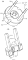
- FIG. 15 is a structural schematic view of a second connector 50 in FIG. 3
- FIG. 16 is a cross-sectional view of the power adapter 100 in FIG. 3
- the second connector 50 is mounted in the first housing 10 and the second housing 20.
- the second connector 50 is configured to be cooperated with a corresponding outlet connector (e.g., a wall outlet) which provides the AC power.
- the second connector 50 abuts against the conductive component 32 (such as the abutting component 323) to construct an electrical path between the second connector 50 and the electronic assembly 30 (such as the abutting component 323).
- the second connector 50 includes a conductive member 51 and a mounting base 52.
- the conductive member 51 is configured to be cooperated with the corresponding outlet connector (e.g., the wall outlet) which provides the AC power to achieve an electrical connection.
- the conductive member 51 may be a pin.
- the conductive member 51 may include a first pin 511 and a second pin 512.
- the conductive member 51 (such as the first pin 511 and the second pin 512) is fixed to the mounting base 52.
- the mounting base 52 may be made of a rigid insulating material.
- the mounting base 52 may be connected to the ejector mechanism 60.
- the ejector mechanism 60 is configured to drive the mounting base 52 to move in response to the relative rotation between the first housing 10 and the second housing 20, such that the conductive member 51 (such as the first pin 511 and the second pin 512) is extended out of or retracted into the second receiving cavity 23.
- a slide-way 521 is defined in the mounting base 52 and configured to receive the guiding component 222 of the second housing 20.
- the mounting base 52 is slidable in the direction of the extension of the guiding component 222.
- the mounting base 52 is connected to the second housing 20 through a relationship between the slide-way 521 and the guiding component 222.
- the slide-way 521 may have a structure such as a hole or a groove.
- the number of the slide-way 521 is at least one. As shown in FIG. 15 , the number of the slide-way 521 is two.
- the slide-way 521 extends along a direction substantially parallel to an axis of the guiding component 222.
- the mounting base 52 may be slidable relative to the second housing 20 along the direction of the extension of the guiding component 222, such that the mounting base 52 is pushed or pulled by the ejector mechanism 60 in response to the relative rotation between the first housing 10 and the second housing 20.
- the conducting member 51 (such as the first pin 511 and the second pin 512) is driven to be slid relative to the second housing 20, such that the conducting member 51 (such as the first pin 511 and the second pin 512) is at least partially located inside the second receiving cavity 23 or outside the second receiving cavity 23.
- the number of the pins may be adjusted according to the actual situations.
- the pins may also include a third pin.
- the conductive member 51 e.g., the first pin 511 is fixed to the mounting base 52.
- the conductive member 51 e.g., the first pin 511 abuts against the first conductive component 32a, such as the abutting component 323 of the first conductive component 32a.
- an end of the first pin 511 is fixed to the mounting base 52, and an end portion of the first pin 511 fixed to the mounting base 52 abuts against the first conductive component 32a, such as abutting against the abutting component 323 of the first conductive component 32a.
- the conductive member 51 e.g., the second pin 512 is fixed to the mounting base 52.
- the second pin 512 abuts against the second conductive component 32b, such as the abutting component 323 of the second conductive component 32b.
- an end of the second pin 512 is fixed to the mounting base 52, and an end portion of the second pin 512 fixed to the mounting base 52 abuts against the second conductive component 32b, such as abutting against the abutting component 323 of the second conductive component 32b.
- the conductive member 51 may also be a connecting head of a connector such as the ⁇ USB connector, the 30-pin connector employed by the device of the Apple Inc., the Lightning ® connector employed by the device of the Apple Inc., and the Type-C connector, etc. That is, the second connector 50 may be replaced by the first connector 40 shown in FIGS. 2 and 3 .
- the first connector 40 shown in FIGS. 2 and 3 may be connected to the first housing 10 and the second housing 20 in the same way of the second connector 50.
- FIG. 17 is a structural schematic view illustrating an assembly of the second housing 20 and the second connector 50 shown in FIG. 16 .
- the conductive member 51 of the second connector 50 extends or is inserted into the second receiving cavity 23, and the guiding components 222 of the second housing 20, such as the first guiding component 2221 and the second guiding component 2223, are disposed in a corresponding slide-way 521 of the mounting base 52 of the second connector 50, respectively.
- the mounting based 52 is allowed to be slidable relative to the second housing 20 in the direction of the extension of the guiding components 222.
- the first pin 511 of the second connector 50 is extended out of the first channel 2111 of the channel 211 or retracted into the second receiving cavity 23, and the second pin 512 of the second connector 50 is extended out of the second channel 2113 of the channel 211 or retracted into the second receiving cavity 23.
- functions of the guiding components 222 are weakened since the channels 211 may also serve as guiders. Consequently, in some embodiments, the guiding components 222 and the slide-way 521 may be omitted.
- FIG. 18 is a structural schematic view illustrating an assembly of the first housing 10, the second housing 20, the second connector 40, and an ejector mechanism 60 shown in FIG. 3 .
- the ejector mechanism 60 is configured to drive the second connector 50 to be extended out of or retracted into the second housing 23 in response to the first housing 10 being rotated around the axis relative to the second housing 20.
- the ejector mechanism 60 may include an ejector component 15, the mounting base 52, and the guiding components 222.
- the ejector member 15 may be arranged on the first housing 10, such as the first side plate 12.
- the mounting base 52 is connected to the ejector component 15.
- the mounting base 52 is slidably connected to the guiding components 222.
- the ejector component 15 is configured to drive the mounting base 52 to slide in the direction of the extension of the guiding components 222 in response to the second housing 20 being rotated around the axis relative to the first housing 10, such that the conductive member 51 mounted on the mounting base 52 is at least partially located inside or outside the second receiving cavity 23.
- the guiding components 222 may be omitted.
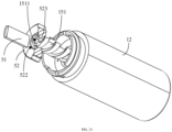
- FIG. 19 is a structural schematic view of the first housing 10 shown in FIG. 18 .
- the ejector component 15 may be made of a rigid material, such as the plastic, the glass, the rubber, the ceramic, the silicon, etc. Of course, the ejector component 15 may also be made of the same material as the first housing 10. The ejector component 15 may also be made of other materials.
- the ejector component 15 is arranged at a position of the first side plate 12 where the first opening 14 is defined.
- the ejector component 15 may include a push-pull rod 151 and a connecting component 152.
- the connecting component 152 is fixed to the first housing 10 (such as the first side plate 12).
- the push-pull rod 151 is fixed to the connecting component 152 and configured to be connected to the mounting base 52.
- An axis of the push-pull rod 151 may be substantially coincided with the axis around which the first housing 10 is rotated relative to the second housing 20.
- the ejector component 15 (such as the push-pull rod 151) is rotated in response to the relative rotation between the first housing 10 and the second housing 20, so as to push or pull the second connector 50, such as the mounting base 52 of the second connector 50.
- the second connector 50 is at least partially located inside or outside the second receiving cavity 23.
- the push-pull rod 151 is a screw rod and connected to the second connector 50 by threads.
- the push-pull rod 151 may be directly fixed to the connecting component 152.
- the push-pull rod 151 is connected to the second housing 20.
- an accommodating slot 1511 is defined in an end portion of the push-pull rod 151 close or adjacent to the second housing 20.
- the protrusion 212 is arranged or received in the accommodating slot 1511, such that the push-pull rod 151 is inserted into and engaged with the second housing 20. In this way, a stability of the push-pull rod 151 is improved.
- FIG. 20 is a structural schematic view of the first housing 10 shown in FIG. 19 .
- the connecting component 152 may have a plate-like structure. Of course, the connecting component 152 may also have other shapes, such as a mesh shape, which is not repeated herein.
- An edge of the connecting component 152 is connected to the first side plate 12 at the position where the first opening 14 is defined.
- the first receiving cavity 13 is defined or enclosed by the connecting component 152, the first bottom plate 11, and the first side plate 12.
- the second receiving cavity 23 is defined or enclosed by the connecting component 152, the second bottom plate 21, and the second side plate 12. That is, the accommodating cavity 101 is divided by the connecting component 152 into two sections, i.e., the first receiving cavity 13 and the second receiving cavity 23, respectively.
- One or more perforations may be defined in the connecting component 152 and penetrates the connecting component 152.
- the perforations may include a first via hole 1521 and a second via hole 1523.
- the perforations (such as the first via hole 1521 and the second via hole 1523) may be in communication with the first receiving cavity 13.
- the electronic assembly 30 (such as the extension component 322) may be disposed in one of the perforations (such as the first via hole 1521 or the second via hole 1523).
- the mounting components 122 are arranged on the ejector component 15
- the mounting components 122 are arranged at a portion of the connecting component 152 close to the first side plate 12.
- the first buckling member 121 may also be arranged on the connecting component 152. That is, the first buckling member 121 may be arranged on the connecting component 152 and/or the first side plate 12.
- the connecting component 152 may be omitted, and the push-pull rod 151 may be extended into the first receiving cavity 13 and directly connected to and fixed to the first housing 10 (such as the first bottom plate 11).
- the ejector component 15 and the first bottom plate 11 may be of an integral structure; or the ejector component 15 and the first side plate 12 may be of an integral structure.
- FIG. 21 is a structural schematic view of the second connector 50 shown in FIG. 18
- FIG. 22 is a cross-sectional view of the second connector 50 shown in FIG. 21
- a screw hole 522 is defined in the mounting base 52.
- the screw hole 522 is provided with threads matched with the threads on the push-pull rod 151, such that the push-pull rod 151 is extended into the screw hole 522 and threaded to the mounting base 52.
- the threads formed in the screw hole 522 are configured to be continuous or discontinuous. When the threads of the screw hole 522 are discontinuous, as shown in FIG. 21 , multiple bumps 523 are arranged in the screw hole 522.
- the push-pull rod 151 is configured to be disposed between the bumps 523, and the push-pull rod 151 is connected to the mounting base 52 through the bumps 523.
- the bumps 523 are configured to be slidable in a direction of extension of threads on a surface of the push-pull rod 151.
- the number of the bumps 523 may be two, and the two bumps 523 are arranged substantially symmetrically.
- the number of the bumps 523 is not limited to two, but may also be three or four. An arrangement of the multiple bumps 523 may be adjusted according to the actual needs.
- a direction of the axis of the push-pull rod 151 is substantially parallel to a direction of extension of the slide-way 521 or the direction of the extension of the guiding components 222.
- FIG. 23 is a structural schematic view illustrating an assembly of the ejector component 15 and the second connector 50 shown in FIG. 18 .
- the end portion of the push-pull rod 151 is disposed in the screw hole 522 defined in the mounting base 52 of the second connector 50.
- the first housing 10 is rotated, such that the push-pull rod 151 is threaded to the second connector 50 (such as the mounting base 52).
- the ejector component 15 (such as the push-pull rod 151) is configured to push the second connector 50 (such as the mounting base 52) to slide along the direction of the axis of the push-pull rod 151, such that the conductive member 51 is extended out of the second receiving cavity 23.
- first pin 511 abuts against the abutting component 323 of the electronic assembly 30 (such as the abutting component 323 of the first conductive component 32a) and the second pin 512 abuts against the abutting component 323 of the electronic assembly 30 (such as the abutting component 323 of the second conductive component 32b), in response to the conductive member 51 (such as the first pin 511 and the second pin 512) being extended out of the second receiving cavity 23.
- the push-pull rod 151 may also have a rod-like structure provided with a gear or a gear assembly.
- the push-pull rod 151 is connected to the mounting base 52 by means of gear engagement.
- the direction of the axis of the push-pull rod 151 may not be parallel to the direction of extension of the guiding components 222.
- the mounting base 52 is provided with a rack configured to be engaged with a gear in the gear assembly.
- the push-pull rod 151 is engaged with the mounting base 52 through the rack and the gear assembly.
- the rack and the gear assembly herein are configured in a scope where a person skilled in the art may understand, which is not repeated herein.
- the push-pull rod 151 drives the mounting base 52, such that the second connector 50 is driven to move.
- the guiding components 222 (such as the first guiding component 2221 and the second guiding component 2223) are configured to guide the mounting base 52.
- the mounting base 52 of the ejector mechanism 60 is omitted, and the guiding components 222 (such as the first guiding component 2221 and the second guiding component 2223) are configured as a part of the ejector mechanism 60.
- the mounting base 52 may be guided by the channels 211 (such as the first channel 2111 and the second channel 2113). Understandably, the mounting base 52 of the ejector mechanism 60 may be omitted, and the channels 211 (such as the first channel 2111 and the second channel 2113) may be configured as a part of the ejector mechanism 60.
- the first connector 40 is fixedly welded to the conductive pins of the printed circuit board 31.
- the printed circuit board 31 and the first connector 40 are mounted in the first receiving cavity 13, and the first connector 40 corresponds to and faces the through hole 111, such that the first connector 40 is electrically connected to the electronic device by passing through the through hole 111.
- the fixing component 321 of each of the one or more conductive components 32 is engaged with the mounting component 122 through the first engaging portion 3211, the second engaging portion 3213, and the third engaging portion 3215.
- the extension component 322 passes through a corresponding one of the perforations (such as the first via hole 1521 and the second via hole 1523), and is fixedly welded to the conductive pins of the printed circuit board 31.
- the second connector 50 is mounted on the ejector component 15.
- the push-pull rod 151 is inserted into the screw hole 522 of the second connector 50, such that the second connector 50 (such as the mounting base 52) is threaded to the push-pull rod 151.
- the first housing 10 is engaged with the second housing 20, and the pins of the second connector 50 correspond to and face the channels 211 one by one.
- the first pin 511 corresponds to and faces the first channel 2111
- the second pin 512 corresponds to and faces the second channel 2113.
- the first pin 511 may extend out from the first channel 2111 and the second pin 512 may extend out from the second channel 2113.
- the second connector 50 (such as slide-ways 521) may be cooperated with the guiding components 222.
- each of the first guiding component 2221 and the second guiding component 2223 is disposed in a corresponding one of slide-ways 521, respectively, such that the second connector 50 is slidable in the direction of the extension of the guiding components 222.
- the second connector 50 is slid out of the second receiving cavity 23 from the channels 211.
- the first pin 511 and the second pin 512 are slid out of the second receiving cavity 23, respectively from the first channel 2111 and the second channel 2113.
- the first buckling member 121 is engaged with the second buckling member 223.
- the first housing 10 is held, and the second housing 20 is rotated. Due to the threads, the mounting base 52 and the push-pull rod 151 are rotated relative to each other.
- the mounting base 52 is moved along the direction of the axis of the push-pull rod 151 through the cooperation between the guiding components 222 (such as the first guiding component 2221 and the second guiding component 2223) and the mounting base 52.
- the first pin 511 and the second pin 512 are driven by the mounting base 52 to be extended out of or retracted into the second receiving housing 23 by changing a direction of rotation of the second housing 20.
- FIGS. 24 and 25 shows a cross-sectional view of the power adapter 100 shown in FIG. 3 , respectively.
- the abutting component 323 of the first conductive component 32a abuts against the first pin 511
- the second abutting component 323 of the second conductive component 32b abuts against the second pin 512.
- the first pin 511 and the second pin 512 are driven by the mounting base 52 to move towards the first housing 10, such that the first abutting component is disconnected from the first pin 511 and the second abutting component is disconnected from the second pin 512.
- the ejector component 15 (such as the push-pull rod 151) is configured to push the second connector 50 (such as the mounting base 52) in response to the relative rotation between the first housing 10 and the second housing 20, such that the second connector 50 (such as the first pin 511 and the second pin 512) is slid in the direction of the extension of the slide-ways 521 to be extended out of the second receiving cavity 23.
- the first pin 511 abuts against the abutting component 323 of the electronic assembly 30 (such as the first conductive component 32a), and the second pin 512 abuts against the second abutting component 323 of the electronic assembly 30 (such as the second conductive component 32b).
- the ejector component 15 (such as the push-pull rod 151) is configured to pull the second connector 50 (such as the mounting base 52) in response to the relative rotation between the first housing 10 and the second housing 20, such that the second connector 50 (such as the first pin 511 and the second pin 512) is slid in the direction of the extension of the slide-ways 521 and retracts into the second receiving cavity 23.
- the first pin 511 is disconnected from the first abutting component 323 of the electronic assembly 30 (such as the first conductive component 32a), and the second pin 512 is disconnected from the second abutting component 323 of the electronic assembly 30 (such as the second conductive component 32b).
- an outer surface of the first housing 10 is substantially flush with an outer surface of the second housing 20 all the time. That is, no corner angle exists between contacting portions of the first housing 10 and the second housing 20, which improves appearance performance.
- a rotating angle required in the relative rotation between the first housing 10 and the second housing 20 to rotate the second connector 50 outside or inside for storage is not limited herein.
- the first housing 10 is able to be rotated by an angle of 360° relative to the second housing 20, to achieve a first state in which the second connector 50 is completely received in the second receiving cavity 23 to a second state in which the second connector 50 is extended out of the second receiving cavity 23 to the maximum extent.
- the rotating angle may also have other values, such as 45°, or 90°, which may be set according to the actual needs and not repeated herein.
- FIG. 26 is a structural schematic view of the power adapter 100 in FIG. 1 having another appearance.
- Both the first housing 10 and the second housing 20 in this power adapter 100 have columnar structures with square cross-sections. Of course, both the first housing 10 and the second housing 20 may also have the columnar structures with polygonal cross-sections.
- the corner angle is generated between the contacting portions of the first housing 10 and the second housing 20, which affects the appearance performance.
- the corner angle is generated between the contacting portions of the first housing 10 and the second housing 20, which affects the storage.
- the corner angle is generated between the contacting portions of the first housing 10 and the second housing 20, which affects usage.
- the rotating angle may be set to be an integer multiple of 90°.
- a first receiving slot 123 is defined at a side of the first side plate 12 of the first housing 10 facing the second housing 20.
- a first magnetic component 124 is arranged in the first receiving slot 123.
- a second receiving slot 224 is defined at a side of the second side plate 22 of the second housing 20 facing the first housing 10.
- a second magnetic component 225 is arranged in the second receiving slot 224.
- the first magnetic component 124 and the second magnetic component 225 are configured to have opposite poles which are attractable.
- the first housing 10 may be controlled to be rotated an integer multiple of 360° relative to the second housing 20, such that the second connector 50 may be slid from the first state in which the second connector 50 is completely received in the second receiving cavity 23 to the second state in which the second connector 50 is extended out of the second receiving cavity 23 to the maximum extent.
- the first magnetic component 124 directly or right faces the second magnetic component 225, and the first magnetic component 124 and the second magnetic component 225 are attracted by each other. In this way, it is easy for the user to perceive that the second housing 10 is rotated to a first right position relative to the second housing 20, where the outer surface of the first housing 10 is substantially flush with the outer surface of the second housing 20 and no corner angle exists between the contacting portions of the first housing 10 and the second housing 20. In this way, it is convenient for the storage.
- the first magnetic component 124 directly or right faces the second magnetic component 225, and the first magnetic component 124 and the second magnetic component 225 are attracted by each other. It is easy for the user to perceive that the second housing 10 is rotated to a second right position relative to the second housing 20, where the outer surface of the second housing 20 is substantially flush with the outer surface of the second housing 20 and no corner angle exists between the contacting portions of the first housing 10 and the second housing 20. In this way, it is convenient for the usage.
- both the number of the first magnetic members 124 and the number of the second magnetic members 225 may be multiple.
- the first magnetic members 124 and the second magnetic members 225 may be evenly and circumferentially distributed around the axis along which the first housing 10 is rotated relative to the second housing 20.
- the number of the first magnetic components 124 is two.
- the outer surface of the first housing 10 is substantially flush with the outer surface of the second housing 20, and no corner angle exists between the contacting portions of the first housing 10 and the second housing 20.
- the second connector 50 In response to the second magnetic component 225 directly or right facing and being attracted by one of the two magnetic components 124, the second connector 50 is in the first state in which the whole of the second connector 50 is received in the second receiving cavity 23. In response to the second magnetic component 225 directly or right facing towards and being attracted by the other one of the two magnetic components 124, the second connector 50 is in the second state in which the second connector 50 is extended out of the second receiving cavity 23 to the maximum extent.
- both the first magnetic component 124 and the second magnetic component 225 may be magnets.
- the first magnetic component 124 and the second magnetic component 225 are configured to indicate right positions and alignment, such that poor appearance performance may be avoided, and user experience may be improved.
- both the first magnetic component 124 and the second magnetic component may be electromagnets.
- the first housing 10 is configured to be concentrically rotated relative to the second housing 20.
- the ejector mechanism 60 is adjusted through the relative rotation between the first housing 10 and the second housing 20 to cause the second connector 50 to displace, such that the second connector 50 is at least partially located outside the accommodating cavity 101 for normal usage or the second connector 50 is located in the accommodating cavity 101 for the storage.
- the technical solution of the present disclosure is simple, reliable, and may achieve unscrewing, locking, and collecting of the power adapter. In this way, a size of a product may be reduced, a misoperation may be avoided, and the user experience may be improved.
Landscapes
- Details Of Connecting Devices For Male And Female Coupling (AREA)
- Casings For Electric Apparatus (AREA)
- Coupling Device And Connection With Printed Circuit (AREA)
Abstract
Description
- The present disclosure relates to the field of electronic devices, and in particular to a power adapter.
- Current power adapters employ fixed plugs and manual lift-off plugs common in the related art. Since the power adapter usually needs to be carried out, a power adapter with the fixed plug is inconvenient to store. Furthermore, when the power adapter with the fixed plug is put in a bag, the power adapter may damage other items in the bag, e.g., scratch a cell phone. The manual lift-off plug is made of metal and has sharp corners. As a result, a power adapter with the manual lift-off plug is difficult to be lifted, and it is easy to damage a nail or scratch skin of a user in a process of lifting the manual lift-off plug.
- According to one aspect of some embodiments of the present disclosure, a power adapter is provided. The power adapter includes a first housing, a second housing, an ejector mechanism, and a first connector. The second housing is connected to the first housing. The first housing and the second housing cooperatively defines an accommodating cavity, and the first housing and the second housing are configured to be concentrically rotatable relative to each other. The ejector mechanism is fixedly connected to the first housing. The first connector is fixedly connected to the ejector mechanism. The ejector mechanism is configured to push or pull the first connector, and enable the first connector to be at least partially located inside the accommodating cavity or outside the accommodating cavity, in response to a relative rotation between the first housing and the second housing.
- According to some embodiments of the present disclosure, a power adapter is provided. The power adapter includes a first housing, a second housing, and a first connector. The first housing and the second housing are configured to be concentrically rotatable relative to each other. The first connector, configured to be extended out of or retracted into the second housing in response to a relative rotation between the first housing and the second housing.
- According to some embodiments of the present disclosure, a power adapter is provided. The power adapter includes a first housing, a second housing, an electronic assembly, a first connector, an ejector mechanism, and a second connector. The first housing defines a first receiving cavity. The second housing defines a second receiving cavity and connected to the first housing. The first housing and the second housing are configured to be concentrically rotatable relative to each other. The electronic assembly includes a printed circuit board arranged in the first receiving cavity; and a conductive component, arranged in the second receiving cavity, and configured to be electrically connected to the printed circuit board. The first connector is arranged in the first receiving cavity and electrically connected to the printed circuit board. The ejector mechanism is arranged in the second receiving cavity and fixedly connected to the first housing. The second connector is mounted on the ejector mechanism. The ejector mechanism is configured to pushing or pulling the second connector and enable the second connector to be at least partially located inside the second receiving cavity or outside the second receiving cavity, in response to the relative rotation between the first housing and the second housing. The second connector is configured to be located outside the second receiving cavity in response to the conductive component being conducted to the second connector, and the conductive component is configured to be disconnected from the second connector in response to the second connector being located inside the second receiving cavity.
- The power adapter provided in some embodiments of the present disclosure includes the first housing and the second housing configured to be concentrically rotatable relative to each other. The ejector mechanism is adjusted through the relative rotation between the first housing and the second housing to cause the first connector to displace. In this way, the first connector is at least partially located outside the accommodating cavity for normal usage or the first connector is located in the accommodating cavity for storage.
- In order to more clearly illustrate technical solutions in the embodiments of the present disclosure, accompanying drawings required in the descriptions for the embodiments will be introduced briefly in the following. Obviously, the accompanying drawings described below are simply some of the embodiments of the present disclosure. For those skilled in the art, other drawings may be obtained based on these accompanying drawings without creative effort.
-
FIG. 1 is a structural schematic view of a power adapter according to an embodiment of the present disclosure. -
FIG. 2 is a structural schematic view of the power adapter inFIG. 1 from another perspective. -
FIG. 3 is an exploded schematic view of the power adapter inFIG. 1 . -
FIG. 4 is a cross-sectional view of the power adapter inFIG. 1 along a line IV-IV inFIG. 1 . -
FIG. 5 is a structural schematic view of a first housing shown inFIG. 3 . -
FIG. 6 is a structural schematic view of the first housing inFIG. 5 from another perspective. -
FIG. 7 is a cross-sectional view of the first housing inFIG. 5 . -
FIG. 8 is a structural schematic view of a second housing shown inFIG. 3 . -
FIG. 9 is a partial cross-sectional view of the second housing inFIG. 8 . -
FIG. 10 is a structural schematic view illustrating an assembly of the first housing and the second housing shown inFIG. 3 . -
FIG. 11 is a structural schematic view illustrating an assembly of an electronic assembly and a first connector shown inFIG. 3 . -
FIG. 12 is a structural schematic view illustrating a conductive component shown inFIG. 11 . -
FIG. 13 is a structural schematic view illustrating an assembly of the first housing, the electronic assembly, and the first connector shown inFIG. 3 . -
FIG. 14 is a structural schematic view illustrating an assembly of the first housing and the electronic assembly shown inFIG. 13 . -
FIG. 15 is a structural schematic view of a second connector inFIG. 3 . -
FIG. 16 is a cross-sectional view of the power adapter inFIG. 3 . -
FIG. 17 is a structural schematic view illustrating an assembly of the second housing and the second connector shown inFIG. 16 . -
FIG. 18 is a structural schematic view illustrating an assembly of the first housing, the second housing, the second connector, and an ejector mechanism shown inFIG. 3 . -
FIG. 19 is a structural schematic view of the first housing shown inFIG. 18 . -
FIG. 20 is a structural schematic view of the first housing shown inFIG. 19 . -
FIG. 21 is a structural schematic view of the second connector shown inFIG. 18 . -
FIG. 22 is a cross-sectional view of the second connector shown inFIG. 21 . -
FIG. 23 is a structural schematic view illustrating an assembly of the ejector mechanism and the second connector shown inFIG. 18 . -
FIG. 24 is a cross-sectional view of the power adapter shown inFIG. 3 . -
FIG. 25 is a cross-sectional view of the power adapter shown inFIG. 3 . -
FIG. 26 is a structural schematic view of the power adapter inFIG. 1 having another appearance. - The present disclosure is further described in detail below in conjunction with the accompanying drawings and embodiments. In particular, it is noted that the following embodiments are configured only to illustrate the present disclosure, but do not limit the scope of the present disclosure. Similarly, the following embodiments are only some but not all embodiments of the present disclosure, and all other embodiments obtained by a person of ordinary skill in the art without creative labor fall within the scope of the present disclosure.
- "Embodiment" herein means that a particular feature, structure, or characteristic described with reference to embodiments may be included in at least one embodiment of the present disclosure. The terms appearing in various places in the specification are not necessarily shown in the same embodiment, and are not exclusive or alternative embodiments that are mutually exclusive with other embodiments. Those skilled in the art will understand explicitly and implicitly that the embodiments described herein may be combined with other embodiments.
- A power adapter is provided in some embodiments of the present disclosure. The power adapter is also called an external power supply, which is a power-supply-voltage convertor of a small portable electronic device and an electronic appliance. An operating principle of the power adapter is to convert an AC input to a DC output. Power adapters have a wall plug type and a desktop type in terms of connection manners.
- It should be noted that, in the following descriptions, terms "mount", "connect", "couple" should be understood in a broad sense unless otherwise expressly specified and limited. For example, the term "connect" may indicates a fixedly connection, a detachable connection, or a one-piece connection; a mechanical connection or an electrical connection; a direct connection or an indirect connection through an intermediate medium thereof, or a fluid communication between insides of two components. Those skilled in the art can understand specific meanings of the above terms herein according to specific cases.
- Electronic devices covered in some embodiments of the present disclosure may include, but are not limited to, cell phones, tablet computers, wearable devices (e.g., watches, bracelets, augmented reality glasses, virtual reality glasses, etc.), smart appliances (e.g., table lamps, fans, light bars, etc.), other audio products (e.g., speakers, storytellers, headphones, etc.), security cameras, set-top boxes, routers, or massage devices.
- As shown in
FIGS. 1-4 ,FIG. 1 is a structural schematic view of a power adapter according to an embodiment of the present disclosure,FIG. 2 is a structural schematic view of the power adapter inFIG. 1 from another perspective,FIG. 3 is an exploded view of the power adapter inFIG. 1 , andFIG. 4 is a cross-sectional view of the power adapter inFIG. 1 along a line IV-IV inFIG. 1 . Thepower adapter 100 may include afirst housing 10, asecond housing 20 engaged with thefirst housing 10, anelectronic assembly 30 disposed in thefirst housing 10 and thesecond housing 20, afirst connector 40 disposed in thefirst housing 10, asecond connector 50 capable of being extending out of or retracting into thesecond housing 20, and anejector mechanism 60 received in thefirst housing 10 and thesecond housing 20 and configured to drive thesecond connector 50 to be extended out of or retracted into thesecond housing 20. - The
first housing 10 may be engaged with thesecond housing 20 to form a housing. Anaccommodating cavity 101 is defined in the housing and configured to accommodate and protect components (such as a printed circuit board, and a transformer, an inductor, a capacitor, a control integrated circuit on the printed circuit board, etc.) in thepower adapter 100. Thefirst housing 10 is rotatable around an axis relative to thesecond housing 20, and thesecond housing 20 is also rotatable around the same axis relative to thefirst housing 10. Theelectronic assembly 30 is arranged in theaccommodating cavity 101 and configured to realize a current conversion or a voltage conversion. For example, theelectronic assembly 30 is configured to convert the AC input to the DC output. Thefirst connector 40 and thesecond connector 50 are electrically connected to theelectronic assembly 30, respectively. Thesecond connector 50 is at least partially located inside theaccommodating cavity 101 or outside theaccommodating cavity 101, in response to a relative rotation between thefirst housing 10 and thesecond housing 20. One of thefirst connector 40 and thesecond connector 50 is configured to be connected to an AC power source (e.g., 110-220 VAC) to allow thepower adapter 100 to receive an AC from the AC power source. The other one of thefirst connector 40 and thesecond connector 50 is configured to be connected to an electronic device to allow thepower adapter 100 to serve as a DC power source (e.g., 5-24 VDC) to output a DC to the electronic device. - In an embodiment, the
first connector 40 may be configured in the same manner as thesecond connector 50, such that thefirst connector 40 is at least partially located inside theaccommodating cavity 101 or outside theaccommodating cavity 101 in response to the relative rotation between thefirst housing 10 and thesecond housing 20. - In some embodiments, the number of the connectors, such as the
first connector 40 and thesecond connector 50, may be one. For example, thefirst connector 40 may be omitted, and theelectronic assembly 30 is connected to the AC power source (e.g., 110-220 VAC) through thesecond connector 50, such that thepower adapter 100 receives the AC from the AC power source. Theelectronic assembly 30 is directly connected to the electronic device rather than connected to the electronic device through thefirst connector 40. That is, thepower adapter 100 is a part of the electronic device. - In another embodiment, the number of the connectors, such as the
first connector 40 and thesecond connector 50, may be at least two. For example, the number of thefirst connector 40 is two, and two electronic devices may be connected through thefirst connector 40. - It should be noted that the terms such as "first", "second", "third", etc., are used herein for purposes of description, and are not intended to indicate or imply relative importance or significance or to imply the number of indicated technical features. Thus, the feature defined with "first", "second", "third", etc., may include one or more of such a feature. In the description of the present disclosure, it should be noted that, "a plurality of" means two or more, such as two, three, etc., unless specified otherwise.
- It can be understood that names such as "first housing", "second housing", and "housing", etc., are interchangeable. For example, "first housing" may also be referred to as "second housing".
- It can be understood that names such as "first connector", "second connector", and "connector", etc., are interchangeable. For example, "first connector" can also be referred to as "second connector".
- As shown in
FIGS. 5-7 ,FIG. 5 is a structural schematic view of afirst housing 10 shown inFIG. 3 ,FIG. 6 is a structural schematic view of thefirst housing 10 inFIG. 5 from another perspective, andFIG. 7 is a cross-sectional view of thefirst housing 10 inFIG. 5 . Thefirst housing 10 may be made of any suitable material, e.g., plastic, rubber, ceramic, silicon, etc. Although thefirst housing 10 is shown as a cylindrical shape, however, the shape of thefirst housing 10 is not limited thereto. Thefirst housing 10 may have any of other shapes required for a particular application. For example, thefirst housing 10 may have one of a rectangular shape, a spherical shape, an irregular shape, etc. - The
first housing 10 may include afirst bottom plate 11 and afirst side plate 12 surrounding or enclosing thefirst bottom plate 11. Thefirst side plate 12 is connected to thefirst bottom plate 11 to form thefirst housing 10 with a first receivingcavity 13 inside. The first receivingcavity 13 of thefirst housing 10 may be configured to receive components in thepower adapter 100 such as a part or a whole of theelectronic assembly 30 and thefirst connector 40. Of course, the first receivingcavity 13 of thefirst housing 10 may also be configured to only receive a portion of thefirst connector 40. In some embodiments, thefirst housing cavity 13 may form a part of theaccommodating cavity 101. Of course, in some embodiments, the first receivingcavity 13 may also form the whole of theaccommodating cavity 101. - The
first bottom plate 11 has a circular plate-like structure. Thefirst bottom plate 11 may have other shapes, such as the rectangular shape, a polygonal shape, an irregular shape, etc., which may be changed according to actual situations. A throughhole 111 may be defined in thefirst bottom plate 11, and the throughhole 111 penetrates thefirst bottom plate 11. The throughhole 111 is in communication with the first receivingcavity 13, and is configured to receive thefirst connector 40. In some embodiments, thefirst connector 40 may be extended out of the first receivingcavity 13 via the throughhole 111. - Understandably, the number of the through
hole 111 may be at least one. Of course, the number of the throughhole 111 may be determined based on the number of thefirst connector 40 and particular application requirements. In another embodiment, the throughhole 111 may be omitted. In some embodiments, the throughhole 111 may be replaced by a recess. For example, the recess is defined in thefirst bottom plate 11 to accommodate thefirst connector 40, such that thefirst connector 40 is located outside the first receivingcavity 13. - The
first side plate 12 may have a cylindrical tubular structure, which is not limited thereto. A shape of thefirst side plate 12 may be changed according to the actual situations, which is not repeated herein. Thefirst side plate 12 extends from an edge of thefirst bottom plate 11 towards a side away from thefirst bottom plate 11, and afirst opening 14 is defined accordingly. Thefirst side plate 12 is engaged with thesecond housing 20 at a position where thefirst opening 14 is defined. - The
first side plate 12 and thefirst bottom plate 11 may be of an integral structure. In an embodiment, thefirst side plate 12 may be glued to thefirst bottom plate 11 to form thefirst housing 10. In an embodiment, thefirst side plate 12 may be fixed to thefirst bottom plate 11 to form thefirst housing 10 by means of threads or a buckle, such that thefirst bottom plate 11 is detachably connected to thefirst side plate 12. It will be understood that the throughhole 111 may also be defined in thefirst side plate 12 when thefirst side plate 12 is connected to thefirst bottom plate 11 to form thefirst housing 10. That is, the throughhole 111 may be defined in thefirst bottom plate 11 and/or thefirst side plate 12. - As shown in
FIGS. 5-7 , thefirst housing 10, such as thefirst side plate 12, is provided with a first bucklingmember 121 at the position where thefirst opening 14 is defined, such that thefirst housing 10 is engaged with thesecond housing 20. The first bucklingmember 121 may include a connectingplate 1211, and the connectingplate 1211 extends from an edge of thefirst side plate 12 at the position where thefirst opening 14 is defined towards a side away from thefirst side plate 12. Agroove 1213 is defined in the connectingplate 1211. Thegroove 1213 is configured to be engaged with a corresponding portion of thesecond housing 20, such that thefirst housing 10 is engaged with thesecond housing 20. In some embodiments, the first bucklingmember 121 may also be configured as other structures arranged on thefirst side plate 12, and the other structures may include at least one of a bump, a buckling hook, a buckling slot, and the like. - The connecting
plate 1211 may be an annular structure. Thegroove 1213 may also be an annular structure. Thegroove 1213 is defined at an outer side of the connectingplate 1211, such that thesecond housing 20 is sleeved on the connectingplate 1211 and engaged with or stuck in thegroove 1213. In this way, thesecond housing 20 is rotatable relative to thefirst housing 10 along a circular track configured by thegroove 1213. Of course, thegroove 1213 may also be defined at an inner side of the connectingplate 1211. Understandably, the number of thegrooves 1213 may also be multiple, andmultiple grooves 1213 are defined in the connectingplate 1211 side by side. In an embodiment, thegroove 1213 may have a discontinuous structure. - By means of the first buckling
member 121, thefirst housing 10 is engaged with thesecond housing 20, and a part structure of thesecond housing 20 is disposed in thegroove 1213 and slidable in thegroove 1213. When the first housing 10 (such as the first buckling member 121) is connected to thesecond housing 20, thesecond housing 20 is allowed to be rotated around the axis relative to thefirst housing 10 under a force. - In an embodiment, a plurality of
slits 1215 may be defined in the connectingplate 1211 to divide the connectingplate 1211 into a plurality of sections. As shown inFIG. 6 , twoslits 1215 are defined in the connectingplate 1211 to divide the connectingplate 1211 into two sections. It will be appreciated that, with theslits 1215, each of the connectingplates 1211 forms one first bucklingmember 121, that is, a plurality of first bucklingmembers 121 may be arranged on thefirst side plate 12. In an embodiment, nogroove 1213 is defined in some of the connectingplates 1211. - Understandably, the
slits 1215 defined in the connectingplate 1211 are configured to allow the first bucklingmembers 121 to have deformation spaces at positions where theslits 1215 are defined, such that each of the connecting plates has an elastic deformation capability. In an engaging process of thefirst housing 10 with thesecond housing 20, the connectingplates 1211 generate elastic deformation to provide clearance for a part structure of thesecond housing 20. In this way, a possibility of damaging thefirst housing 10 and/or thesecond housing 20 during an assembly process or a disassembly process may be reduced. - As shown in
FIGS. 5-7 , thefirst housing 10, such as the connectingplate 1211, is also provided with a mountingcomponent 122. The mountingcomponent 122 is configured to mount some of components configured to fix theelectronic assembly 30. The number of the mountingcomponents 122 may be two, i.e., afirst mounting component 1221 and asecond mounting component 1223. Of course, the number of the mountingcomponents 122 may be adjusted according to actual needs. For example, the number of the mountingcomponents 122 may be not limited to two, such as one or three. - Both the
first mounting component 1221 and thesecond mounting component 1223 may have plate-like structures. Both thefirst mounting component 1221 and thesecond mounting component 1223 extend from an edge of the first buckling member 121 (such as the connecting plate 1211) to a side away from the first bucklingmember 121. Thefirst mounting component 1221 and thesecond mounting component 1223 may be arranged substantially symmetrically. - Understandably, the mounting
component 122 may be arranged on the first buckling member 121 (such as the connecting plate 1211). The mountingcomponent 122 and the first bucklingmember 121 may be of an integral structure. The first bucklingmember 121 is configured to fix theelectronic assembly 30. In an embodiment, the mountingcomponent 122 may be directly arranged on thefirst side plate 12. For example, the mountingcomponent 122 may extend from an edge of thefirst side plate 12 at thefirst opening 14 to a side away from thefirst side plate 12. In some embodiments, the mountingcomponent 122 may also be arranged on theejector mechanism 60. In some embodiments, the mountingcomponent 122 may also be omitted. - As shown in
FIG. 8-9 ,FIG. 8 is a structural schematic view of thesecond housing 20 shown inFIG. 3 , andFIG. 9 is a partial cross-sectional view of thesecond housing 20 inFIG. 8 . Thesecond housing 20 may be made of any suitable material, e.g., plastic, rubber, ceramic, silicon, etc. Although thesecond housing 20 is shown as a cylindrical shape, however, the shape of thesecond housing 20 is not limited thereto. Thesecond housing 20 may have any of other shapes required for the particular application. For example, thesecond housing 20 may have one of a rectangular shape, a spherical shape, or an irregular shape, etc. - The
second housing 20 may include asecond bottom plate 21 and asecond side plate 22. Thesecond side plate 22 surrounds or is enclosed around thesecond bottom plate 21 and is connected to thesecond bottom plate 21 to form thesecond housing 20 with a second receivingcavity 23. Thesecond side plate 22 may further enclose at a side of thesecond side plate 22 opposite to thesecond bottom plate 21 to form or define asecond opening 24, such that thesecond side plate 22 is engaged with the first housing 10 (such as the first buckling member 121) at a position where thesecond opening 24 is defined. The second receivingcavity 23 is configured to receive the components in thepower adapter 100 such as the part of theelectronic assembly 30 and thesecond connector 50. Thesecond housing 20 is engaged with thefirst housing 10 to form theaccommodating cavity 101. That is, the second receivingcavity 23 may form a part of theaccommodating cavity 101. Of course, in some embodiments, the second receivingcavity 23 may also form the whole of theaccommodating cavity 101. - The
second bottom plate 21 has a circular plate-like structure. Thesecond bottom plate 21 may have other shapes, such as the rectangular shape, the polygonal shape, or the irregular shape, etc., which may be changed according to the actual situations. Achannel 211 is defined in thesecond bottom plate 21 and penetrates thesecond bottom plate 21. In some embodiments, thechannel 211 may include afirst channel 2111 and asecond channel 2113. Thechannel 211, such as thefirst channel 2111 and thesecond channel 2113, is in communication with the second receivingcavity 23. Thesecond connector 50 is extended out of the channel 211 (such as thefirst channel 2111 or the second channel 2113) or retracted into the second receivingcavity 23,. - Understandably, the number of the
channel 211 may be one or multiple, which is determined according to the number of thesecond connector 50 and the particular application requirements. In some embodiments, thefirst channel 2111 or thesecond channel 2113 may be omitted. In some embodiments, thechannel 211 may also be omitted. - The
second bottom plate 21 is provided with aprotrusion 212. Theprotrusion 212 is configured to be connected to theejector mechanism 60 to stabilize or fix theejector mechanism 60. - In some embodiments, the
protrusion 212 may be omitted. In some embodiments, theprotrusion 212 may also be replaced by a recess or a through hole. That is, the recess or the through hole may be defined in thesecond bottom plate 21, and theejector mechanism 60 may extend into the recess or the through-hole, such that thesecond bottom plate 21 is connected to theejector mechanism 60. In this way, theejector mechanism 60 is stabilized or fixed. - In an embodiment, the
second side plate 22 may have a circular tubular structure. Thesecond side plate 22 may also have other shapes, and the shape of thesecond side plate 22 may be designed according to the actual situations, which is not repeated herein. Thesecond side plate 22 extends from an edge of thesecond bottom plate 21 towards a side away from thesecond bottom plate 21, and thesecond opening 24 is defined accordingly. Thesecond side plate 22 is engaged with the first housing 10 (such as the first buckling member 121) at the position where thesecond opening 24 is defined. Thesecond side plate 22 and thesecond bottom plate 21 may be of an integral structure. In an embodiment, thesecond side plate 22 may be glued to thesecond bottom plate 21 to form thesecond housing 20. In an embodiment, thesecond side plate 22 may be fixed to thesecond bottom plate 21 to form thesecond housing 10 by means of threads or a buckle, such that thesecond bottom plate 21 is detachably connected to thesecond side plate 22. It will be understood that the channel 211 (such as thefirst channel 2111 and the second channel 2113) may also be defined in thesecond side plate 22 when thesecond side plate 22 is connected to thesecond bottom plate 21 to form thesecond housing 20. That is, thechannel 211 may also be defined in thesecond bottom plate 21 and/or thesecond side plate 22. - As shown in
FIG. 8 , ananti-slip pattern 221 is defined on an outer surface of the second housing 20 (such as the second side plate 22), which is convenient for the user to hold thesecond housing 20 and further rotate thesecond housing 20. In this way, thesecond housing 20 is enabled to be rotated around the axis relative to thefirst housing 10. - The second housing 20 (such as the second side plate 22) is provided with a
guiding component 222 in the second receivingcavity 23. In some embodiments, the guidingcomponent 222 may include, for example, afirst guiding component 2221 and asecond guiding component 2223. The guidingcomponent 222, such as thefirst guiding component 2221 and thesecond guiding component 2223, may be configured to be connected to thesecond connector 50, to guide thesecond connector 50 to be slid in a direction of extension of the guiding component 222 (such as thefirst guiding component 2221 and the second guiding component 2223), such that thesecond connector 50 is able to be extended out of thechannel 211 of thesecond housing 20 or retracted into the second receivingcavity 23. The guiding component 222 (such as thefirst guiding component 2221 and the second guiding component 2223) may have a rod-like shape or a plate-like shape. In an embodiment, thefirst guiding component 2221 and thesecond guiding component 2223 may be arranged substantially symmetrically. In an embodiment, the number of the guidingcomponent 222 may be at least one. For example, one of thefirst guiding component 2221 and thesecond guiding component 2223 may be omitted. - It is understood that, since the guiding component 222 (such as the
first guiding component 2221 and the second guiding component 2223) is arranged in the second receivingcavity 23, the guiding component 222 (such as thefirst guiding component 2221 and the second guiding component 2223) may also be arranged on thesecond bottom plate 21 rather than thesecond side plate 22. In some embodiments, the guiding component 222 (such as thefirst guiding component 2221 and the second guiding component 2223) may be arranged on both thesecond bottom plate 21 and thesecond side plate 22. - As shown in
FIG. 9 , a second bucklingmember 223 may be arranged on a portion of the second housing 20 (such as the second side plate 22) where thesecond opening 24 is defined, such that thesecond housing 20 is engaged with the first housing 10 (such as the first buckling member 121) via the second bucklingmember 223. The second bucklingmember 223 is a flange extending from an edge of thesecond side plate 22 where thesecond opening 24 is defined towards a side away from thesecond side plate 22. The second bucklingmember 223 is engaged in thegroove 1213, such that the second bucklingmember 223 is buckled with the first bucklingmember 121 and slidable in thegroove 1213. In some embodiments, the second bucklingmember 223 may be at least one of a bump, a buckling hook, a buckling slot, and the like, which is determined according to different structures of the first bucklingmember 121. It can be understood that the flange may have a discontinuous structure. - In an embodiment, both the first buckling
member 121 and the second bucklingmember 223 may be replaced by a magnet or an electromagnet to achieve the connection between thefirst housing 10 and thesecond housing 20. - As shown in
FIG. 10, FIG. 10 is a structural schematic view illustrating an assembly of thefirst housing 10 and thesecond housing 20 shown inFIG. 3 . When thefirst housing 10 is engaged with thesecond housing 20, the first bucklingmember 121 is engaged with the second bucklingmember 223. In an embodiment, the second bucklingmember 223 is sleeved on an outer side of the first bucklingmember 121, and the second bucklingmember 223 is disposed in thegroove 1213 defined in the connectingplate 1211 and slidable in thegroove 1213, such that thesecond housing 10 is enabled to be rotated around the axis relative to thesecond housing 20. - It can be understood that names "first buckling member", "second buckling member", and "buckling member" can be interchanged. For example, the "first buckling member" may also be referred to as the "second buckling member".
- As shown in
FIGS. 11-14 ,FIG. 11 is a structural schematic view illustrating an assembly of anelectronic assembly 30 and afirst connector 40 shown inFIG. 3 ,FIG. 12 is a structural schematic view of a conductive component shown inFIG. 11 ,FIG. 13 is a structural schematic view illustrating an assembly of thefirst housing 10, theelectronic assembly 30, and thefirst connector 40 shown inFIG. 3 , andFIG. 14 is a structural schematic view illustrating an assembly of thefirst housing 10 and theelectronic assembly 30 shown inFIG. 13 . It should be noted that theejector mechanism 60 is removed inFIG. 13 in order to better describe and show a connection relationship between one or moreconductive components 32 and thefirst housing 10. Theelectronic assembly 30 may be configured to implement the DC output of thefirst connector 40 and the AC input of thesecond connector 50. Theelectronic assembly 30 may include a printedcircuit board 31 and the one or moreconductive components 32. The printedcircuit board 31 is electrically connected to the one or moreconductive components 32. The printedcircuit board 31 is electrically connected to thefirst connector 40. The one or moreconductive components 32 are electrically connected to thesecond connector 50. The printedcircuit board 31 may be configured to implement a conversion between the AC and the DC. - The printed
circuit board 31 may be mounted in the first receivingcavity 13 of thefirst housing 10. The printedcircuit board 31 includes a circuit formed thereon, such as a common mode choke, the transformer, the control integrated circuit, a high voltage circuit (e.g., AC), a low voltage circuit (e.g., DC), a filter circuit, or the like. The printedcircuit board 31 may include a component such as the capacitor, the inductor, a resistor, a transistor, or the like. The printedcircuit board 31 may be manufactured by any one of conventional techniques. Conductive pins may be arranged on the printedcircuit board 31 and configured to be connected to and fix thefirst connector 40 and the one or moreconductive components 32. - In an embodiment, the printed
circuit board 31 may also be provided with a Bluetooth module. The printedcircuit board 31 pair and communicates with the electronic device such as a cell phone, a computer, etc., via the Bluetooth module. Theelectronic assembly 30 may also include a battery, a button, an indicator, a buzzer, and a speaker, etc., which are arranged on thefirst housing 10. The battery is configured to supply power for the Bluetooth module, the indicator, the buzzer, and the speaker, etc. Some functions of the power adapter, such as controlling the Bluetooth module to be paired with the electronic device, sending a Bluetooth signal, and the battery discharging, may be controlled through the button. In some embodiments, thepower adapter 100 is allowed to serve as a portable charger due to the existence of the battery. - Understandably, it is easy for the user to forget a position of the
power adapter 100 due to a small volume of thepower adapter 100. In this case, the Bluetooth module is configured to allow thepower adapter 100 to be paired with the electronic device such as the cell phone, the laptop, and the like, so as to achieve a communication connection between thepower adapter 100 and the electronic device, and achieve the following functions. - Within a coverage of the Bluetooth, the electronic device, such as the cell phone and the laptop, sends a control signal searching for the
power adapter 100 to thepower adapter 100 through the Bluetooth module. Under the control of the control signal, thepower adapter 100 may show position information thereof through a specific beep, sound, light, etc., to inform the user of the position thereof. - Within the coverage of the Bluetooth, when the button on the
power adapter 100 is pressed down, thepower adapter 100 sends another control signal searching for the electronic device (such as the cell phone, and the laptop, etc.) to the electronic device (such as the cell phone, and the laptop, etc.) paired with thepower adapter 100 via the Bluetooth module. The electronic device (such as the cell phone, and the computer, etc.) shows position information thereof through a specific ring tone, light, etc., to inform the user of the position thereof. - As shown in
FIGS. 12 and13 , the one or moreconductive components 32 may be made of a solid conductive metal material such as gold, silver, iron, copper, aluminum, or an alloy. The number of the one or moreconductive components 32 may be two, i.e., the one or moreconductive components 32 include a firstconductive component 32a and a secondconductive component 32b. Of course, the number of the one or moreconductive components 32 may be adjusted according to the actual situations and is not limited to two. For example, the number of the one or moreconductive components 32 may also be three or four. The one or moreconductive components 32 may be fixed to the first housing 10 (such as the mounting component 122). In an embodiment, the firstconductive component 32a may be fixed to thefirst mounting component 1221, and the secondconductive component 32b is fixed to thesecond mounting component 1223. The one or more conductive components 32 (such as the firstconductive component 32a and the secondconductive component 32b) may extend into the first receivingcavity 13 of thefirst housing 10 to be electrically connected to the conductive pins of the printedcircuit board 31. The one or more conductive components 32 (such as the firstconductive component 32a and the secondconductive component 32b) may be electrically connected to thesecond connector 50, such that an electrical path is constructed between the printedcircuit board 31 and thesecond connector 50. - As shown in
FIGS. 13 and 14 , each of the conductive components 32 (such as the firstconductive component 32a and the secondconductive component 32b) may include afixing component 321 configured to be engaged with, e.g., fixedly engaged with, a corresponding one of the mountingcomponents 122, anextension component 322 extending from the fixingcomponent 321, and anabutting component 323. Theextension component 322 extends from the fixingcomponent 321 into the first receivingcavity 13 and is electrically connected to the conductive pins of the printedcircuit board 31. In an embodiment, theextension component 322 is connected to the conductive pins of the printedcircuit board 31 by means of welding. Theextension component 322 may be bent from an edge of thefixing component 321 in a bending manner, such that theextension component 322 and thefixing component 321 are located on two opposite side surfaces of the corresponding one of the mountingcomponents 122, respectively. Theextension component 322 then extends towards the first receivingcavity 13. The abuttingcomponent 323 is bent upwards from a middle at bottom edge of thefixing component 321. The abuttingcomponent 323 is configured to abut against thesecond connector 50 to construct an electrical path therebetween. - As shown in
FIG. 14 , the fixingcomponent 321 may surround or enclose around a side surface of the corresponding one of the mountingcomponents 122, e.g., thefirst mounting component 1221. The fixingcomponent 321 includes a first engagingportion 3211 and a secondengaging portion 3213. The firstengaging portion 3211 and the second engagingportion 3213 are engaged with an edge of the corresponding one of the mountingcomponents 122, e.g., thefirst mounting component 1221, respectively, such that the fixingcomponent 321 is fixedly connected to the corresponding one of the mountingcomponents 122, e.g., thefirst mounting component 1221. Understandably, the fixingcomponent 321 may also be fixedly connected to the corresponding one of the mountingcomponents 122, e.g., thefirst mounting component 1221 by other means, such as through a screwed structure, a glued structure, etc. In an embodiment, the first engagingportion 3211 and the second engagingportion 3213 may have hook-like structures formed by bending both edges of thefixing component 321, respectively. - In an embodiment, the first engaging
portion 3211 is arranged on a first end of thefixing component 321, the second engagingportion 3213 is arranged on a second end of the fixedcomponent 321, and the first end is opposite to the second end. In some embodiments, at least one thirdengaging portion 3215 is arrange between the first end and the second end of thefixing component 321. The thirdengaging portion 3215 is configured to be fixed to another edge of the corresponding one of the mountingcomponents 122, e.g., thefirst mounting component 1221. The thirdengaging portion 3215 may also have the hook-like structure formed by bending another edge of thefixing component 321. - The
extension component 322 and thefixing component 321 may be of an integral structure. Theextension component 322 may extend from the edge of thefixing component 321. In an embodiment, the fixingcomponent 321 may be directly fixed to theejector mechanism 60 rather than fixed to the corresponding one of the mountingcomponents 122. In an embodiment, the fixingcomponent 321 may be omitted, theextension component 322 is fixedly connected to theabutting component 323, and each of the one or moreconductive components 32 is fixed to theejector mechanism 60 through theextension component 322, such that theconductive component 32 is fixed to theejector mechanism 60. In an embodiment, both thefixing component 321 and theextension component 322 are omitted. - The abutting
component 323 is a strip-like structure and has two ends opposite to each other. One of the two ends of theabutting component 323 is fixedly connected to thefixing component 321 by means of, for example, welding, gluing, screwing, and the like. The other end of theabutting component 323 abuts against thesecond connector 50 to construct an electrical path among the printedcircuit board 31, thesecond connector 50, and theabutting component 323. - In an embodiment, the abutting
component 323 has a property of the elastic deformation. A reliable electrical connection between theabutting component 323 and thesecond connector 50 may be achieved through the elastic deformation of theabutting component 323. In an embodiment, the abuttingcomponent 323 and thefixing component 321 may be of an integral structure. The abuttingcomponent 323 extends from the edge of thefixing component 321. In an embodiment, the fixingcomponent 321 and theextension component 322 are omitted, and theabutting component 323 is fixed to thefirst housing 10 or theejector mechanism 60. The abuttingcomponent 323 is electrically connected to the printedcircuit board 31 to construct an electrical path between theabutting component 323 and the printedcircuit board 31. - As shown in
FIGS. 3 and4 , thefirst connector 40 is electrically connected to the conductive pins of the printedcircuit board 31 for outputting the DC. Thefirst connector 40 is configured to be cooperated with the electronic device, e.g., thefirst connector 40 may be a USB connector. Thefirst connector 40 may also be any of other connectors. Thepower adapter 100 may be coupled to the electronic device via thefirst connector 40 to supply the power to the electronic device or charge the electronic device. For example, one end of a cable with a complementary USB connector may be connected to thefirst connector 40, and the other end of the cable may have any of other suitable connectors which is configured to be cooperated with the electronic device. These connectors include but are not limited to, a µUSB connector, a 30-pin connector employed by a device of Apple Inc., a Lightning® connector employed by the device of the Apple Inc., a Type-C connector, etc. - In some embodiments, the
first connector 40 is an electromagnetic induction coil and configured to supply the power to the electronic device or charge the electronic device through electromagnetic induction between thefirst connector 40 and the electronic device. - In an embodiment, the
first connector 40 may have a cable electrically connected to the printedcircuit board 31, e.g., the conductive pins of the printedcircuit board 31. Thefirst connector 40 is directly connected to a connector on the electronic device. In an embodiment, thefirst bottom plate 11 and thefirst side plate 12 are designed to be detachable from each other. Thefirst connector 40 having the cable may be disposed in the first receivingcavity 13 for storage. - As shown in
FIGS. 15 and 16, FIG. 15 is a structural schematic view of asecond connector 50 inFIG. 3 , andFIG. 16 is a cross-sectional view of thepower adapter 100 inFIG. 3 . Thesecond connector 50 is mounted in thefirst housing 10 and thesecond housing 20. Thesecond connector 50 is configured to be cooperated with a corresponding outlet connector (e.g., a wall outlet) which provides the AC power. Thesecond connector 50 abuts against the conductive component 32 (such as the abutting component 323) to construct an electrical path between thesecond connector 50 and the electronic assembly 30 (such as the abutting component 323). - The
second connector 50 includes aconductive member 51 and a mountingbase 52. Theconductive member 51 is configured to be cooperated with the corresponding outlet connector (e.g., the wall outlet) which provides the AC power to achieve an electrical connection. Theconductive member 51 may be a pin. For example, theconductive member 51 may include afirst pin 511 and asecond pin 512. The conductive member 51 (such as thefirst pin 511 and the second pin 512) is fixed to the mountingbase 52. The mountingbase 52 may be made of a rigid insulating material. The mountingbase 52 may be connected to theejector mechanism 60. Theejector mechanism 60 is configured to drive the mountingbase 52 to move in response to the relative rotation between thefirst housing 10 and thesecond housing 20, such that the conductive member 51 (such as thefirst pin 511 and the second pin 512) is extended out of or retracted into the second receivingcavity 23. - A slide-
way 521 is defined in the mountingbase 52 and configured to receive theguiding component 222 of thesecond housing 20. The mountingbase 52 is slidable in the direction of the extension of the guidingcomponent 222. The mountingbase 52 is connected to thesecond housing 20 through a relationship between the slide-way 521 and theguiding component 222. In an embodiment, the slide-way 521 may have a structure such as a hole or a groove. The number of the slide-way 521 is at least one. As shown inFIG. 15 , the number of the slide-way 521 is two. The slide-way 521 extends along a direction substantially parallel to an axis of the guidingcomponent 222. - The mounting
base 52 may be slidable relative to thesecond housing 20 along the direction of the extension of the guidingcomponent 222, such that the mountingbase 52 is pushed or pulled by theejector mechanism 60 in response to the relative rotation between thefirst housing 10 and thesecond housing 20. As a result, the conducting member 51 (such as thefirst pin 511 and the second pin 512) is driven to be slid relative to thesecond housing 20, such that the conducting member 51 (such as thefirst pin 511 and the second pin 512) is at least partially located inside the second receivingcavity 23 or outside the second receivingcavity 23. - The number of the pins, such as the
first pin 511 and thesecond pin 512, may be adjusted according to the actual situations. For example, the pins may also include a third pin. - As shown in
FIGS. 15 and 16 , theconductive member 51, e.g., thefirst pin 511 is fixed to the mountingbase 52. Theconductive member 51, e.g., thefirst pin 511 abuts against the firstconductive component 32a, such as the abuttingcomponent 323 of the firstconductive component 32a. In an embodiment, an end of thefirst pin 511 is fixed to the mountingbase 52, and an end portion of thefirst pin 511 fixed to the mountingbase 52 abuts against the firstconductive component 32a, such as abutting against the abuttingcomponent 323 of the firstconductive component 32a. - The
conductive member 51, e.g., thesecond pin 512 is fixed to the mountingbase 52. Thesecond pin 512 abuts against the secondconductive component 32b, such as the abuttingcomponent 323 of the secondconductive component 32b. In an embodiment, an end of thesecond pin 512 is fixed to the mountingbase 52, and an end portion of thesecond pin 512 fixed to the mountingbase 52 abuts against the secondconductive component 32b, such as abutting against the abuttingcomponent 323 of the secondconductive component 32b. - Understandably, the
conductive member 51 may also be a connecting head of a connector such as the µUSB connector, the 30-pin connector employed by the device of the Apple Inc., the Lightning® connector employed by the device of the Apple Inc., and the Type-C connector, etc. That is, thesecond connector 50 may be replaced by thefirst connector 40 shown inFIGS. 2 and3 . Thefirst connector 40 shown inFIGS. 2 and3 may be connected to thefirst housing 10 and thesecond housing 20 in the same way of thesecond connector 50. - As shown in
FIG. 17, FIG. 17 is a structural schematic view illustrating an assembly of thesecond housing 20 and thesecond connector 50 shown inFIG. 16 . When thesecond connector 50 is connected to thesecond housing 20, theconductive member 51 of thesecond connector 50 extends or is inserted into the second receivingcavity 23, and the guidingcomponents 222 of thesecond housing 20, such as thefirst guiding component 2221 and thesecond guiding component 2223, are disposed in a corresponding slide-way 521 of the mountingbase 52 of thesecond connector 50, respectively. The mounting based 52 is allowed to be slidable relative to thesecond housing 20 in the direction of the extension of the guidingcomponents 222. For example, in a process of the mountingbase 52 sliding relative to thesecond housing 20, thefirst pin 511 of thesecond connector 50 is extended out of thefirst channel 2111 of thechannel 211 or retracted into the second receivingcavity 23, and thesecond pin 512 of thesecond connector 50 is extended out of thesecond channel 2113 of thechannel 211 or retracted into the second receivingcavity 23. It will be appreciated that in a process of the mountingbase 52 sliding relative to thesecond housing 20, functions of the guidingcomponents 222 are weakened since thechannels 211 may also serve as guiders. Consequently, in some embodiments, the guidingcomponents 222 and the slide-way 521 may be omitted. - As shown in
FIG. 18, FIG. 18 is a structural schematic view illustrating an assembly of thefirst housing 10, thesecond housing 20, thesecond connector 40, and anejector mechanism 60 shown inFIG. 3 . Theejector mechanism 60 is configured to drive thesecond connector 50 to be extended out of or retracted into thesecond housing 23 in response to thefirst housing 10 being rotated around the axis relative to thesecond housing 20. Theejector mechanism 60 may include anejector component 15, the mountingbase 52, and the guidingcomponents 222. Theejector member 15 may be arranged on thefirst housing 10, such as thefirst side plate 12. The mountingbase 52 is connected to theejector component 15. The mountingbase 52 is slidably connected to the guidingcomponents 222. Theejector component 15 is configured to drive the mountingbase 52 to slide in the direction of the extension of the guidingcomponents 222 in response to thesecond housing 20 being rotated around the axis relative to thefirst housing 10, such that theconductive member 51 mounted on the mountingbase 52 is at least partially located inside or outside the second receivingcavity 23. In an embodiment, the guidingcomponents 222 may be omitted. - As shown in
FIG. 19, FIG. 19 is a structural schematic view of thefirst housing 10 shown inFIG. 18 . Theejector component 15 may be made of a rigid material, such as the plastic, the glass, the rubber, the ceramic, the silicon, etc. Of course, theejector component 15 may also be made of the same material as thefirst housing 10. Theejector component 15 may also be made of other materials. Theejector component 15 is arranged at a position of thefirst side plate 12 where thefirst opening 14 is defined. Theejector component 15 may include a push-pull rod 151 and a connectingcomponent 152. The connectingcomponent 152 is fixed to the first housing 10 (such as the first side plate 12). The push-pull rod 151 is fixed to the connectingcomponent 152 and configured to be connected to the mountingbase 52. An axis of the push-pull rod 151 may be substantially coincided with the axis around which thefirst housing 10 is rotated relative to thesecond housing 20. The ejector component 15 (such as the push-pull rod 151) is rotated in response to the relative rotation between thefirst housing 10 and thesecond housing 20, so as to push or pull thesecond connector 50, such as the mountingbase 52 of thesecond connector 50. In this way, thesecond connector 50 is at least partially located inside or outside the second receivingcavity 23. - In some embodiments, the push-
pull rod 151 is a screw rod and connected to thesecond connector 50 by threads. The push-pull rod 151 may be directly fixed to the connectingcomponent 152. In an embodiment, the push-pull rod 151 is connected to thesecond housing 20. For example, anaccommodating slot 1511 is defined in an end portion of the push-pull rod 151 close or adjacent to thesecond housing 20. Theprotrusion 212 is arranged or received in theaccommodating slot 1511, such that the push-pull rod 151 is inserted into and engaged with thesecond housing 20. In this way, a stability of the push-pull rod 151 is improved. - As shown in
FIG. 20, FIG. 20 is a structural schematic view of thefirst housing 10 shown inFIG. 19 . The connectingcomponent 152 may have a plate-like structure. Of course, the connectingcomponent 152 may also have other shapes, such as a mesh shape, which is not repeated herein. An edge of the connectingcomponent 152 is connected to thefirst side plate 12 at the position where thefirst opening 14 is defined. The first receivingcavity 13 is defined or enclosed by the connectingcomponent 152, thefirst bottom plate 11, and thefirst side plate 12. The second receivingcavity 23 is defined or enclosed by the connectingcomponent 152, thesecond bottom plate 21, and thesecond side plate 12. That is, theaccommodating cavity 101 is divided by the connectingcomponent 152 into two sections, i.e., the first receivingcavity 13 and the second receivingcavity 23, respectively. - One or more perforations may be defined in the connecting
component 152 and penetrates the connectingcomponent 152. In an embodiment, the perforations may include a first viahole 1521 and a second viahole 1523. The perforations (such as the first viahole 1521 and the second via hole 1523) may be in communication with the first receivingcavity 13. As shown inFIG. 24 , the electronic assembly 30 (such as the extension component 322) may be disposed in one of the perforations (such as the first viahole 1521 or the second via hole 1523). Understandably, in case that the mountingcomponents 122 are arranged on theejector component 15, the mountingcomponents 122 are arranged at a portion of the connectingcomponent 152 close to thefirst side plate 12. Of course, in some embodiments, the first bucklingmember 121 may also be arranged on the connectingcomponent 152. That is, the first bucklingmember 121 may be arranged on the connectingcomponent 152 and/or thefirst side plate 12. - In some embodiments, the connecting
component 152 may be omitted, and the push-pull rod 151 may be extended into the first receivingcavity 13 and directly connected to and fixed to the first housing 10 (such as the first bottom plate 11). - Understandably, the
ejector component 15 and thefirst bottom plate 11 may be of an integral structure; or theejector component 15 and thefirst side plate 12 may be of an integral structure. - As shown in
FIGS. 21 and 22, FIG. 21 is a structural schematic view of thesecond connector 50 shown inFIG. 18 , andFIG. 22 is a cross-sectional view of thesecond connector 50 shown inFIG. 21 . Ascrew hole 522 is defined in the mountingbase 52. Thescrew hole 522 is provided with threads matched with the threads on the push-pull rod 151, such that the push-pull rod 151 is extended into thescrew hole 522 and threaded to the mountingbase 52. In an embodiment, the threads formed in thescrew hole 522 are configured to be continuous or discontinuous. When the threads of thescrew hole 522 are discontinuous, as shown inFIG. 21 ,multiple bumps 523 are arranged in thescrew hole 522. The push-pull rod 151 is configured to be disposed between thebumps 523, and the push-pull rod 151 is connected to the mountingbase 52 through thebumps 523. Thebumps 523 are configured to be slidable in a direction of extension of threads on a surface of the push-pull rod 151. In an embodiment, the number of thebumps 523 may be two, and the twobumps 523 are arranged substantially symmetrically. Of course, the number of thebumps 523 is not limited to two, but may also be three or four. An arrangement of themultiple bumps 523 may be adjusted according to the actual needs. In an embodiment, a direction of the axis of the push-pull rod 151 is substantially parallel to a direction of extension of the slide-way 521 or the direction of the extension of the guidingcomponents 222. - As shown in
FIG. 23, FIG. 23 is a structural schematic view illustrating an assembly of theejector component 15 and thesecond connector 50 shown inFIG. 18 . When theejector component 15 is connected to thesecond connector 50, the end portion of the push-pull rod 151 is disposed in thescrew hole 522 defined in the mountingbase 52 of thesecond connector 50. Thefirst housing 10 is rotated, such that the push-pull rod 151 is threaded to the second connector 50 (such as the mounting base 52). - As shown in
FIG. 18 , in response to the relative rotation between thefirst housing 10 and thesecond housing 20, the ejector component 15 (such as the push-pull rod 151) is configured to push the second connector 50 (such as the mounting base 52) to slide along the direction of the axis of the push-pull rod 151, such that theconductive member 51 is extended out of the second receivingcavity 23. In addition, thefirst pin 511 abuts against the abuttingcomponent 323 of the electronic assembly 30 (such as the abuttingcomponent 323 of the firstconductive component 32a) and thesecond pin 512 abuts against the abuttingcomponent 323 of the electronic assembly 30 (such as the abuttingcomponent 323 of the secondconductive component 32b), in response to the conductive member 51 (such as thefirst pin 511 and the second pin 512) being extended out of the second receivingcavity 23. - It will be appreciated that the push-
pull rod 151 may also have a rod-like structure provided with a gear or a gear assembly. The push-pull rod 151 is connected to the mountingbase 52 by means of gear engagement. The direction of the axis of the push-pull rod 151 may not be parallel to the direction of extension of the guidingcomponents 222. In an embodiment, the mountingbase 52 is provided with a rack configured to be engaged with a gear in the gear assembly. The push-pull rod 151 is engaged with the mountingbase 52 through the rack and the gear assembly. The rack and the gear assembly herein are configured in a scope where a person skilled in the art may understand, which is not repeated herein. - It is understood that the push-
pull rod 151 drives the mountingbase 52, such that thesecond connector 50 is driven to move. The guiding components 222 (such as thefirst guiding component 2221 and the second guiding component 2223) are configured to guide the mountingbase 52. In an embodiment, the mountingbase 52 of theejector mechanism 60 is omitted, and the guiding components 222 (such as thefirst guiding component 2221 and the second guiding component 2223) are configured as a part of theejector mechanism 60. - In some embodiments, the mounting
base 52 may be guided by the channels 211 (such as thefirst channel 2111 and the second channel 2113). Understandably, the mountingbase 52 of theejector mechanism 60 may be omitted, and the channels 211 (such as thefirst channel 2111 and the second channel 2113) may be configured as a part of theejector mechanism 60. - During the assembly of the
power adapter 100, as shown inFIGS. 11 and13 , thefirst connector 40 is fixedly welded to the conductive pins of the printedcircuit board 31. The printedcircuit board 31 and thefirst connector 40 are mounted in the first receivingcavity 13, and thefirst connector 40 corresponds to and faces the throughhole 111, such that thefirst connector 40 is electrically connected to the electronic device by passing through the throughhole 111. The fixingcomponent 321 of each of the one or moreconductive components 32 is engaged with the mountingcomponent 122 through the first engagingportion 3211, the second engagingportion 3213, and the thirdengaging portion 3215. Theextension component 322 passes through a corresponding one of the perforations (such as the first viahole 1521 and the second via hole 1523), and is fixedly welded to the conductive pins of the printedcircuit board 31. - As shown in
FIG. 23 , thesecond connector 50 is mounted on theejector component 15. The push-pull rod 151 is inserted into thescrew hole 522 of thesecond connector 50, such that the second connector 50 (such as the mounting base 52) is threaded to the push-pull rod 151. - As shown in
FIGS. 4 and17 , thefirst housing 10 is engaged with thesecond housing 20, and the pins of thesecond connector 50 correspond to and face thechannels 211 one by one. For example, thefirst pin 511 corresponds to and faces thefirst channel 2111, and thesecond pin 512 corresponds to and faces thesecond channel 2113. Thefirst pin 511 may extend out from thefirst channel 2111 and thesecond pin 512 may extend out from thesecond channel 2113. The second connector 50 (such as slide-ways 521) may be cooperated with the guidingcomponents 222. That is, each of thefirst guiding component 2221 and thesecond guiding component 2223 is disposed in a corresponding one of slide-ways 521, respectively, such that thesecond connector 50 is slidable in the direction of the extension of the guidingcomponents 222. In this way, thesecond connector 50 is slid out of the second receivingcavity 23 from thechannels 211. In an embodiment, thefirst pin 511 and thesecond pin 512 are slid out of the second receivingcavity 23, respectively from thefirst channel 2111 and thesecond channel 2113. The first bucklingmember 121 is engaged with the second bucklingmember 223. - As shown in
FIGS. 16 and17 , during the usage, thefirst housing 10 is held, and thesecond housing 20 is rotated. Due to the threads, the mountingbase 52 and the push-pull rod 151 are rotated relative to each other. The mountingbase 52 is moved along the direction of the axis of the push-pull rod 151 through the cooperation between the guiding components 222 (such as thefirst guiding component 2221 and the second guiding component 2223) and the mountingbase 52. Thefirst pin 511 and thesecond pin 512 are driven by the mountingbase 52 to be extended out of or retracted into the second receivinghousing 23 by changing a direction of rotation of thesecond housing 20. -
FIGS. 24 and25 shows a cross-sectional view of thepower adapter 100 shown inFIG. 3 , respectively. When thefirst pin 511 and thesecond pin 512 are at least partially located outside the second receivingcavity 23, the abuttingcomponent 323 of the firstconductive component 32a abuts against thefirst pin 511, and the secondabutting component 323 of the secondconductive component 32b abuts against thesecond pin 512. When retracted into the second receivingcavity 23, thefirst pin 511 and thesecond pin 512 are driven by the mountingbase 52 to move towards thefirst housing 10, such that the first abutting component is disconnected from thefirst pin 511 and the second abutting component is disconnected from thesecond pin 512. - The ejector component 15 (such as the push-pull rod 151) is configured to push the second connector 50 (such as the mounting base 52) in response to the relative rotation between the
first housing 10 and thesecond housing 20, such that the second connector 50 (such as thefirst pin 511 and the second pin 512) is slid in the direction of the extension of the slide-ways 521 to be extended out of the second receivingcavity 23. In response to the second connector 50 (such as thefirst pin 511 and the second pin 512) being extended out of the second receivingcavity 23, thefirst pin 511 abuts against the abuttingcomponent 323 of the electronic assembly 30 (such as the firstconductive component 32a), and thesecond pin 512 abuts against the secondabutting component 323 of the electronic assembly 30 (such as the secondconductive component 32b). - The ejector component 15 (such as the push-pull rod 151) is configured to pull the second connector 50 (such as the mounting base 52) in response to the relative rotation between the
first housing 10 and thesecond housing 20, such that the second connector 50 (such as thefirst pin 511 and the second pin 512) is slid in the direction of the extension of the slide-ways 521 and retracts into the second receivingcavity 23. In response to the second connector 50 (such as thefirst pin 511 and the second pin 512) being retracted into the second receivingcavity 23, thefirst pin 511 is disconnected from the firstabutting component 323 of the electronic assembly 30 (such as the firstconductive component 32a), and thesecond pin 512 is disconnected from the secondabutting component 323 of the electronic assembly 30 (such as the secondconductive component 32b). - As shown in
FIG. 1 , in response to the relative rotation between thefirst housing 10 and thesecond housing 20, an outer surface of thefirst housing 10 is substantially flush with an outer surface of thesecond housing 20 all the time. That is, no corner angle exists between contacting portions of thefirst housing 10 and thesecond housing 20, which improves appearance performance. A rotating angle required in the relative rotation between thefirst housing 10 and thesecond housing 20 to rotate thesecond connector 50 outside or inside for storage is not limited herein. - In an embodiment, the
first housing 10 is able to be rotated by an angle of 360° relative to thesecond housing 20, to achieve a first state in which thesecond connector 50 is completely received in the second receivingcavity 23 to a second state in which thesecond connector 50 is extended out of the second receivingcavity 23 to the maximum extent. Of course, the rotating angle may also have other values, such as 45°, or 90°, which may be set according to the actual needs and not repeated herein. - As shown in
FIG. 26, FIG. 26 is a structural schematic view of thepower adapter 100 inFIG. 1 having another appearance. Both thefirst housing 10 and thesecond housing 20 in thispower adapter 100 have columnar structures with square cross-sections. Of course, both thefirst housing 10 and thesecond housing 20 may also have the columnar structures with polygonal cross-sections. In response to the relative rotation between thefirst housing 10 and thesecond housing 20, the corner angle is generated between the contacting portions of thefirst housing 10 and thesecond housing 20, which affects the appearance performance. In response to thesecond connector 50 being in the first state in which thesecond connector 50 is completely received in the second receivingcavity 23, the corner angle is generated between the contacting portions of thefirst housing 10 and thesecond housing 20, which affects the storage. In response to thesecond connector 50 being in the second state in which thesecond connector 50 is extended out of the second receivingcavity 23 to the maximum extent, the corner angle is generated between the contacting portions of thefirst housing 10 and thesecond housing 20, which affects usage. - Therefore, it is necessary to limit the rotating angle required in the relative rotation between the
first housing 10 and thesecond housing 20 to rotate thesecond connector 50 outside or inside for storage, to ensure that the outer surface of thefirst housing 10 may be substantially flush with the outer surface of thesecond housing 20 in both a storage state and a usage state, and no corner angle exists between the contacting portions of thefirst housing 10 and thesecond housing 20. In this way, the appearance performance of thepower adapter 100 may be improved. For example, the rotating angle may be set to be an integer multiple of 90°. - As shown in
FIG. 26 , afirst receiving slot 123 is defined at a side of thefirst side plate 12 of thefirst housing 10 facing thesecond housing 20. A firstmagnetic component 124 is arranged in thefirst receiving slot 123. Asecond receiving slot 224 is defined at a side of thesecond side plate 22 of thesecond housing 20 facing thefirst housing 10. A secondmagnetic component 225 is arranged in thesecond receiving slot 224. The firstmagnetic component 124 and the secondmagnetic component 225 are configured to have opposite poles which are attractable. Thefirst housing 10 may be controlled to be rotated an integer multiple of 360° relative to thesecond housing 20, such that thesecond connector 50 may be slid from the first state in which thesecond connector 50 is completely received in the second receivingcavity 23 to the second state in which thesecond connector 50 is extended out of the second receivingcavity 23 to the maximum extent. - In response to the
second connector 50 being in the first state in which thesecond connector 50 is completely received in the second receivingcavity 23, the firstmagnetic component 124 directly or right faces the secondmagnetic component 225, and the firstmagnetic component 124 and the secondmagnetic component 225 are attracted by each other. In this way, it is easy for the user to perceive that thesecond housing 10 is rotated to a first right position relative to thesecond housing 20, where the outer surface of thefirst housing 10 is substantially flush with the outer surface of thesecond housing 20 and no corner angle exists between the contacting portions of thefirst housing 10 and thesecond housing 20. In this way, it is convenient for the storage. - In response to the
second connector 50 being slid to the second state where thesecond connector 50 is extended out of the second receivingcavity 23 to the maximum extent, the firstmagnetic component 124 directly or right faces the secondmagnetic component 225, and the firstmagnetic component 124 and the secondmagnetic component 225 are attracted by each other. It is easy for the user to perceive that thesecond housing 10 is rotated to a second right position relative to thesecond housing 20, where the outer surface of thesecond housing 20 is substantially flush with the outer surface of thesecond housing 20 and no corner angle exists between the contacting portions of thefirst housing 10 and thesecond housing 20. In this way, it is convenient for the usage. - It can be understood that both the number of the first
magnetic members 124 and the number of the secondmagnetic members 225 may be multiple. The firstmagnetic members 124 and the secondmagnetic members 225 may be evenly and circumferentially distributed around the axis along which thefirst housing 10 is rotated relative to thesecond housing 20. For example, the number of the firstmagnetic components 124 is two. In response to the secondmagnetic component 225 directly or right facing and being attracted by any one of the twomagnetic components 124, the outer surface of thefirst housing 10 is substantially flush with the outer surface of thesecond housing 20, and no corner angle exists between the contacting portions of thefirst housing 10 and thesecond housing 20. In response to the secondmagnetic component 225 directly or right facing and being attracted by one of the twomagnetic components 124, thesecond connector 50 is in the first state in which the whole of thesecond connector 50 is received in the second receivingcavity 23. In response to the secondmagnetic component 225 directly or right facing towards and being attracted by the other one of the twomagnetic components 124, thesecond connector 50 is in the second state in which thesecond connector 50 is extended out of the second receivingcavity 23 to the maximum extent. - Understandably, both the first
magnetic component 124 and the secondmagnetic component 225 may be magnets. The firstmagnetic component 124 and the secondmagnetic component 225 are configured to indicate right positions and alignment, such that poor appearance performance may be avoided, and user experience may be improved. In some embodiments with the battery, both the firstmagnetic component 124 and the second magnetic component may be electromagnets. - According to the above embodiments of the present disclosure, the
first housing 10 is configured to be concentrically rotated relative to thesecond housing 20. Theejector mechanism 60 is adjusted through the relative rotation between thefirst housing 10 and thesecond housing 20 to cause thesecond connector 50 to displace, such that thesecond connector 50 is at least partially located outside theaccommodating cavity 101 for normal usage or thesecond connector 50 is located in theaccommodating cavity 101 for the storage. The technical solution of the present disclosure is simple, reliable, and may achieve unscrewing, locking, and collecting of the power adapter. In this way, a size of a product may be reduced, a misoperation may be avoided, and the user experience may be improved. - The above descriptions above are only some embodiments of the present disclosure. The scope of the present disclosure is not limited by the above descriptions. Any equivalent structure transformation or equivalent process transformation of the present disclosure made based on contents of the specification and the drawings of the present disclosure, or direct or indirect applications in other related technical fields, are all similarly included within the scope of the present disclosure.
Claims (33)
- A power adapter, comprising:a first housing;a second housing, connected to the first housing, wherein the first housing and the second housing cooperatively defines an accommodating cavity, and the first housing and the second housing are configured to be concentrically rotatable relative to each other;an ejector mechanism, fixedly connected to the first housing; anda first connector, fixedly connected to the ejector mechanism, wherein the ejector mechanism is configured to push or pull the first connector, and enable the first connector to be at least partially located inside the accommodating cavity or outside the accommodating cavity, in response to a relative rotation between the first housing and the second housing.
- The power adapter according to claim 1, wherein the ejector mechanism comprises:an ejector component, fixedly connected to the first housing; anda mounting base, mounted on the ejector component and slidably connected to the second housing;wherein the first connector is mounted on the mounting base, and the ejector component is configured to push or pull the mounting base and enable the first connector to be at least partially located inside the accommodating cavity or outside the accommodating cavity, in response to the relative rotation between the first housing and the second housing.
- The power adapter according to claim 2, wherein the ejector mechanism further comprises:
a guiding component, arranged in the second housing and slidably connected to the mounting base, wherein the mounting base is configured to be slidable in a direction of extension of the guiding component. - The power adapter according to claim 2 or 3, wherein a first receiving cavity and a first opening are defined in the first housing, the first receiving cavity is in communication with an outside of the first housing via the first opening, and the first housing is engaged with the second housing at a position where the first opening is defined.
- The power adapter according to claim 4, wherein a second receiving cavity and a second opening are defined in the second housing, the second receiving cavity is in communication with an outside of the second housing via the second opening, and a portion of the second housing where the second opening is defined is engaged with a portion of the first housing where the first opening is defined.
- The power adapter according to claim 5, wherein a first buckling member is arranged on the portion of the first housing where the first opening is defined, the first buckling member comprises a connecting plate, and a groove is defined in the connecting plate; and
a second buckling member is arranged on the portion of the second housing where the second opening is defined, the second buckling member comprises a flange arranged on an edge of the second housing where the second opening is defined, and the flange is configured to be received in the groove, engaged with the connecting plate, and slidable relative to the first housing in a direction of extension of the groove. - The power adapter according to claim 6, wherein a first magnetic component is arranged on the portion of the first housing where the first opening is defined, a second magnetic component is arranged on the portion of the second housing where the second opening is defined, the first magnetic component and the second magnetic component are configured to have opposite poles which are attractable, and an outer face of the first housing is flush with an outer face of the second housing in response to the first magnetic component facing and attracting the second magnetic component.
- The power adapter according to any one of claims 5-7, wherein the first housing and/or the second housing has a cylindrical shape.
- The power adapter according to any one of claims 5-7, wherein the first housing and/or the second housing has a columnar structure with a polygonal cross section.
- The power adapter according to claim 7, wherein at least one first receiving slot is defined in the portion of the first housing where the first opening is defined, and each of the at least one first receiving slot is arranged with the first magnetic component; and
at least one second receiving slot is defined in the portion of the second housing where the second opening is defined, and each of the at least one second receiving slot is arranged with the second magnetic component. - The power adapter according to claim 4, wherein the ejector component comprises:a connecting component, arranged on a portion of the first housing where the first opening is defined; anda push-pull rod, arranged on the connecting component, wherein the mounting base is mounted on the push-pull rod, and the push-pull rod is configured to push or pull the mounting base and enable the first connector to be at least partially located inside the accommodating cavity or outside the accommodating cavity, in response to the relative rotation between the first housing and the second housing.
- The power adapter according to claim 11, wherein a screw hole is defined in the mounting base, a bump is arranged in the screw hole, a thread is formed on the push-pull rod, the push-pull rod is arranged in the screw hole and connected to the bump, and the bump is configured to be slidable in a direction of extension of the thread.
- The power adapter according to claim 11, wherein a channel is defined in the second housing, the accommodating cavity is in communication with an outside of the second housing via the channel, and the first connector is configured to be extended out of the channel or retracted into the accommodating cavity in response to the relative rotation between the first housing and the second housing.
- The power adapter according to claim 13, wherein the push-pull rod is inserted into and engaged with the second housing, and the first housing and the second housing are configured to be rotatable relative to each other around an axis of the push-pull rod.
- The power adapter according to claim 14, wherein an accommodating slot is defined in the push-pull rod, a protrusion is arranged on the first housing, the protrusion is configured to be arranged in the accommodating slot, and the protrusion is coaxial with the push-pull rod.
- The power adapter according to claim 4, further comprising:an electronic assembly, arranged in the first receiving cavity and configured to be electrically connected to the first connector; anda second connector, electrically connected to the electronic assembly.
- The power adapter according to claim 16, wherein a through hole is defined in the first housing, and the second connector is received in the through hole.
- The power adapter according to claim 16, wherein the electronic assembly comprises:a printed circuit board, electrically connected to the second connector; andone or more conductive components, electrically connected to the printed circuit board and configured to be electrically connected to the first connector.
- The power adapter according to claim 18, wherein each of the conductive components comprises:a fixing component, fixed to the first housing;an extension component, electrically connected to the fixing component and the printed circuit board; andan abutting component, electrically connected to the fixing component and configured to be electrically connected to the first connector.
- The power adapter according to claim 19, wherein the first connector comprises:a first pin and a second pin, arranged on the mounting base, wherein the first pin and the second pin are configured to be extended out of or retracted into the accommodating cavity in response to the relative rotation between the first housing and the second housing;wherein the number of the conductive components is two, the two conductive components comprise a first conductive component and a second conductive component, the first conductive component is configured to abut against the first pin, and the second conductive component is configured to abut against the second pin.
- The power adapter according to claim 19, wherein
a mounting component is arranged on a portion of the first housing where the first opening is defined, the fixing component surrounds a side surface of the mounting component, the fixing component comprises a first engaging portion and a second engaging portion, and the first engaging portion and the second engaging portion are fixedly engaged with an edge of the mounting component, respectively. - The power adapter according to claim 18, wherein the electronic assembly further comprises:
a Bluetooth module, configured to be communicated with an electronic device, wherein the Bluetooth module is configured to send a control signal searching for the electronic device to the electronic device and receive another control signal searching for the power adapter from the electronic device, and the power adapter is configured to show position information of the power adapter in response to the Bluetooth module receiving the another control signal. - The power adapter according to claim 2 or 3, wherein the ejector component is connected to the mounting base by means of threads.
- The power adapter according to claim 2 or 3, wherein a rack is arranged on the mounting base, and the ejector component comprises:a rod structure, fixedly connected to the first housing; anda gear or a gear assembly, mounted on the rod structure and engaged with the rack.
- The power adapter according to claim 2, wherein the first connector comprises a conductive member fixed on the mounting base, a channel is defined in the second housing, the second housing is configured to guide the conductive member arranged in the channel, and the conductive member is configured to be extended out of the channel or retracted into the accommodating cavity in response to the relative rotation between the first housing and the second housing.
- A power adapter, comprising:a first housing;a second housing, wherein the first housing and the second housing are configured to be concentrically rotatable relative to each other; anda first connector, configured to be extended out of or retracted into the second housing in response to a relative rotation between the first housing and the second housing.
- The power adapter according to claim 26, wherein the first connector comprises:a mounting base, disposed in the second housing; anda pin, disposed on the mounting base.
- The power adapter according to claim 27, wherein an ejector component is arranged on the first housing and disposed in the second housing, the mounting base is mounted on the ejector component, and the ejector component is configured to push or pull the mounting base and enable the pin to be extended out of or retracted into the second housing, in response to the relative rotation between the first housing and the second housing.
- The power adapter according to claim 28, wherein the ejector component is connected to the mounting base by means of threads.
- The power adapter according to any one of claims 27-29, wherein a guiding component is arranged on the second housing, a slide-way is formed on the mounting base, the guiding component is disposed in the slide-way, and the mounting base is configured to be slidable in a direction of extension of the guiding component.
- The power adapter according to any one of claims 27-29, wherein a channel is defined in the second housing, an inside of the second housing is in communication with an outside of the second housing via the channel, the second housing is configured to guide the pin inserted in the channel, and the pin is configured to be extended out of the channel or retracted into the second housing in response to the relative rotation between the first housing and the second housing.
- The power adapter according to any one of claims 27-29, further comprising:a second connector, arranged in the first housing;a printed circuit board, arranged in the first housing and electrically connected to the second connector; anda conductive component, arranged in the second housing, electrically connected to the printed circuit board, and configured to be electrically connected to the first connector.
- A power adapter, comprising:a first housing, defining a first receiving cavity;a second housing, defining a second receiving cavity and connected to the first housing, wherein the first housing and the second housing are configured to be concentrically rotatable relative to each other;an electronic assembly, comprising:a printed circuit board, arranged in the first receiving cavity; anda conductive component, arranged in the second receiving cavity and configured to be electrically connected to the printed circuit board;a first connector, arranged in the first receiving cavity and electrically connected to the printed circuit board;an ejector mechanism, arranged in the second receiving cavity and fixedly connected to the first housing; anda second connector, mounted on the ejector mechanism, wherein the ejector mechanism is configured to push or pull the second connector and enable the second connector to be at least partially located inside the second receiving cavity or outside the second receiving cavity, in response to the relative rotation between the first housing and the second housing;wherein the second connector is configured to be located outside the second receiving cavity in response to the conductive component being conducted to the second connector, and the conductive component is configured to be disconnected from the second connector in response to the second connector being located inside the second receiving cavity.
Applications Claiming Priority (2)
| Application Number | Priority Date | Filing Date | Title |
|---|---|---|---|
| CN202011182575.1A CN112186412B (en) | 2020-10-29 | 2020-10-29 | Power adapter |
| PCT/CN2021/113801 WO2022088870A1 (en) | 2020-10-29 | 2021-08-20 | Power adapter |
Publications (2)
| Publication Number | Publication Date |
|---|---|
| EP4220868A1 true EP4220868A1 (en) | 2023-08-02 |
| EP4220868A4 EP4220868A4 (en) | 2024-03-20 |
Family
ID=73917519
Family Applications (1)
| Application Number | Title | Priority Date | Filing Date |
|---|---|---|---|
| EP21884602.0A Pending EP4220868A4 (en) | 2020-10-29 | 2021-08-20 | POWER ADAPTER |
Country Status (3)
| Country | Link |
|---|---|
| EP (1) | EP4220868A4 (en) |
| CN (2) | CN112186412B (en) |
| WO (1) | WO2022088870A1 (en) |
Families Citing this family (6)
| Publication number | Priority date | Publication date | Assignee | Title |
|---|---|---|---|---|
| CN112186412B (en) * | 2020-10-29 | 2022-08-05 | Oppo广东移动通信有限公司 | Power adapter |
| CN113067188B (en) * | 2021-03-24 | 2023-04-14 | Oppo广东移动通信有限公司 | Power Adapter |
| CN113644492B (en) * | 2021-04-19 | 2024-06-25 | Oppo广东移动通信有限公司 | Power adapter and electronic equipment assembly |
| CN115275670B (en) * | 2021-04-30 | 2025-02-11 | Oppo广东移动通信有限公司 | Power adapters and electronic equipment components |
| CN113410700B (en) * | 2021-06-22 | 2022-12-27 | Oppo广东移动通信有限公司 | Power adapter |
| CN115654423B (en) * | 2022-12-25 | 2023-05-09 | 荣耀终端有限公司 | A lampshade and electronic equipment |
Family Cites Families (16)
| Publication number | Priority date | Publication date | Assignee | Title |
|---|---|---|---|---|
| CN2702483Y (en) * | 2003-11-19 | 2005-05-25 | 台均科技(深圳)有限公司 | Player with telescopic interface plug |
| TWM292566U (en) * | 2005-11-25 | 2006-06-21 | Far East College | Lipstick structure with jam |
| CN201084840Y (en) * | 2007-03-22 | 2008-07-09 | 冠德科技(深圳)有限公司 | A power supply adapter |
| US7713073B2 (en) * | 2008-01-25 | 2010-05-11 | Transpower Technology Co., Ltd. | Power adapter |
| TWM364344U (en) * | 2008-12-05 | 2009-09-01 | Kimcco Internat Ltd | Power converter with rotational-type single push handle |
| CN102244996B (en) * | 2010-05-11 | 2014-10-08 | 华为终端有限公司 | Universal serial bus (USB) equipment |
| CN101872911B (en) * | 2010-05-18 | 2012-11-07 | 智嘉通讯科技(东莞)有限公司 | Rotary selection push-out type multinational power supply adapter |
| CN103022786B (en) * | 2013-01-06 | 2015-07-08 | 深圳市睿德电子实业有限公司 | Safety plug structure and safety-enhanced power supply utilizing same |
| CN204361352U (en) * | 2014-12-19 | 2015-05-27 | 富泰华工业(深圳)有限公司 | Plug |
| CN107634363B (en) * | 2016-07-19 | 2019-09-06 | 国基电子(上海)有限公司 | Telescopic attaching plug |
| US9831622B1 (en) * | 2017-04-14 | 2017-11-28 | Yuying Lin | Universal socket converter with power bank |
| CN109803033B (en) * | 2017-11-17 | 2020-11-17 | Oppo广东移动通信有限公司 | Shell assembly, functional assembly and mobile terminal |
| TWM565429U (en) * | 2018-05-18 | 2018-08-11 | 金鋐科技股份有限公司 | Mobile power bank adapter plug |
| CN209730374U (en) * | 2018-12-25 | 2019-12-03 | 深圳造物部落科技有限公司 | A kind of flexible table top electrical power connection block |
| CN209561818U (en) * | 2019-03-23 | 2019-10-29 | 深圳市科秀科技有限公司 | A kind of micro usb adapter and its connector |
| CN112186412B (en) * | 2020-10-29 | 2022-08-05 | Oppo广东移动通信有限公司 | Power adapter |
-
2020
- 2020-10-29 CN CN202011182575.1A patent/CN112186412B/en active Active
- 2020-10-29 CN CN202210651843.2A patent/CN114914750B/en active Active
-
2021
- 2021-08-20 EP EP21884602.0A patent/EP4220868A4/en active Pending
- 2021-08-20 WO PCT/CN2021/113801 patent/WO2022088870A1/en not_active Ceased
Also Published As
| Publication number | Publication date |
|---|---|
| EP4220868A4 (en) | 2024-03-20 |
| WO2022088870A1 (en) | 2022-05-05 |
| CN112186412B (en) | 2022-08-05 |
| CN114914750B (en) | 2024-12-17 |
| CN114914750A (en) | 2022-08-16 |
| CN112186412A (en) | 2021-01-05 |
Similar Documents
| Publication | Publication Date | Title |
|---|---|---|
| EP4220868A1 (en) | Power adapter | |
| EP3913780B1 (en) | Power adapter | |
| US9312673B2 (en) | Low voltage power receptacle | |
| US7845974B2 (en) | Power strip | |
| US20150097519A1 (en) | Wireless charger with coil position adjustability | |
| US20160072327A1 (en) | Dock for Portable Electronic Devices | |
| US9176531B1 (en) | Apparatus for providing utility receptacles and cables at a selected location on a workstation | |
| GB2399466A (en) | Battery charging system | |
| CN111128041B (en) | Light and thin LED display box and LED display screen | |
| EP3278198A1 (en) | Interlocking integrated battery structure for an electronic stylus | |
| TWI665838B (en) | Connector and electronic device system applying the same | |
| US20090161332A1 (en) | Socket with power supply | |
| WO2021150292A1 (en) | Magnet-assisted wireless charging and devices therefor | |
| WO2020186022A1 (en) | Wall plate system for data and/or power exchange | |
| CN113067188B (en) | Power Adapter | |
| CN219610939U (en) | Charging wire storage module and combined charging device | |
| WO2022205875A1 (en) | Wireless charging apparatus and smart glasses assembly | |
| TWI459654B (en) | Magnetic force self-alignment electric connector assembly | |
| CN222515198U (en) | Comes with a charging cable | |
| CN219286751U (en) | Power adapter | |
| CN211124830U (en) | A light and thin LED display box and LED display | |
| US6299477B1 (en) | Self-centering power adapter | |
| CN210780168U (en) | A wireless charging stand | |
| CN211908453U (en) | Charger with bluetooth speaker | |
| CN218044363U (en) | Drawer that can supply to charge and contain its desk |
Legal Events
| Date | Code | Title | Description |
|---|---|---|---|
| STAA | Information on the status of an ep patent application or granted ep patent |
Free format text: STATUS: THE INTERNATIONAL PUBLICATION HAS BEEN MADE |
|
| PUAI | Public reference made under article 153(3) epc to a published international application that has entered the european phase |
Free format text: ORIGINAL CODE: 0009012 |
|
| STAA | Information on the status of an ep patent application or granted ep patent |
Free format text: STATUS: REQUEST FOR EXAMINATION WAS MADE |
|
| 17P | Request for examination filed |
Effective date: 20230427 |
|
| AK | Designated contracting states |
Kind code of ref document: A1 Designated state(s): AL AT BE BG CH CY CZ DE DK EE ES FI FR GB GR HR HU IE IS IT LI LT LU LV MC MK MT NL NO PL PT RO RS SE SI SK SM TR |
|
| DAV | Request for validation of the european patent (deleted) | ||
| DAX | Request for extension of the european patent (deleted) | ||
| A4 | Supplementary search report drawn up and despatched |
Effective date: 20240215 |
|
| RIC1 | Information provided on ipc code assigned before grant |
Ipc: H01R 24/68 20110101ALN20240209BHEP Ipc: H01R 13/66 20060101ALN20240209BHEP Ipc: H01R 13/44 20060101ALN20240209BHEP Ipc: H01R 13/04 20060101ALI20240209BHEP Ipc: H01R 13/60 20060101AFI20240209BHEP |
|
| STAA | Information on the status of an ep patent application or granted ep patent |
Free format text: STATUS: EXAMINATION IS IN PROGRESS |
|
| 17Q | First examination report despatched |
Effective date: 20251021 |