EP4220822A1 - Secondary battery and method for manufacturing same - Google Patents
Secondary battery and method for manufacturing same Download PDFInfo
- Publication number
- EP4220822A1 EP4220822A1 EP20955135.7A EP20955135A EP4220822A1 EP 4220822 A1 EP4220822 A1 EP 4220822A1 EP 20955135 A EP20955135 A EP 20955135A EP 4220822 A1 EP4220822 A1 EP 4220822A1
- Authority
- EP
- European Patent Office
- Prior art keywords
- outer package
- secondary battery
- electrode body
- accommodated
- content
- Prior art date
- Legal status (The legal status is an assumption and is not a legal conclusion. Google has not performed a legal analysis and makes no representation as to the accuracy of the status listed.)
- Pending
Links
Images


Classifications
-
- H—ELECTRICITY
- H01—ELECTRIC ELEMENTS
- H01M—PROCESSES OR MEANS, e.g. BATTERIES, FOR THE DIRECT CONVERSION OF CHEMICAL ENERGY INTO ELECTRICAL ENERGY
- H01M50/00—Constructional details or processes of manufacture of the non-active parts of electrochemical cells other than fuel cells, e.g. hybrid cells
- H01M50/10—Primary casings; Jackets or wrappings
-
- H—ELECTRICITY
- H01—ELECTRIC ELEMENTS
- H01M—PROCESSES OR MEANS, e.g. BATTERIES, FOR THE DIRECT CONVERSION OF CHEMICAL ENERGY INTO ELECTRICAL ENERGY
- H01M10/00—Secondary cells; Manufacture thereof
- H01M10/04—Construction or manufacture in general
- H01M10/049—Processes for forming or storing electrodes in the battery container
-
- H—ELECTRICITY
- H01—ELECTRIC ELEMENTS
- H01M—PROCESSES OR MEANS, e.g. BATTERIES, FOR THE DIRECT CONVERSION OF CHEMICAL ENERGY INTO ELECTRICAL ENERGY
- H01M10/00—Secondary cells; Manufacture thereof
- H01M10/04—Construction or manufacture in general
- H01M10/0436—Small-sized flat cells or batteries for portable equipment
-
- H—ELECTRICITY
- H01—ELECTRIC ELEMENTS
- H01M—PROCESSES OR MEANS, e.g. BATTERIES, FOR THE DIRECT CONVERSION OF CHEMICAL ENERGY INTO ELECTRICAL ENERGY
- H01M10/00—Secondary cells; Manufacture thereof
- H01M10/04—Construction or manufacture in general
- H01M10/0468—Compression means for stacks of electrodes and separators
-
- H—ELECTRICITY
- H01—ELECTRIC ELEMENTS
- H01M—PROCESSES OR MEANS, e.g. BATTERIES, FOR THE DIRECT CONVERSION OF CHEMICAL ENERGY INTO ELECTRICAL ENERGY
- H01M10/00—Secondary cells; Manufacture thereof
- H01M10/05—Accumulators with non-aqueous electrolyte
- H01M10/058—Construction or manufacture
- H01M10/0585—Construction or manufacture of accumulators having only flat construction elements, i.e. flat positive electrodes, flat negative electrodes and flat separators
-
- H—ELECTRICITY
- H01—ELECTRIC ELEMENTS
- H01M—PROCESSES OR MEANS, e.g. BATTERIES, FOR THE DIRECT CONVERSION OF CHEMICAL ENERGY INTO ELECTRICAL ENERGY
- H01M50/00—Constructional details or processes of manufacture of the non-active parts of electrochemical cells other than fuel cells, e.g. hybrid cells
- H01M50/10—Primary casings; Jackets or wrappings
- H01M50/102—Primary casings; Jackets or wrappings characterised by their shape or physical structure
- H01M50/103—Primary casings; Jackets or wrappings characterised by their shape or physical structure prismatic or rectangular
-
- H—ELECTRICITY
- H01—ELECTRIC ELEMENTS
- H01M—PROCESSES OR MEANS, e.g. BATTERIES, FOR THE DIRECT CONVERSION OF CHEMICAL ENERGY INTO ELECTRICAL ENERGY
- H01M50/00—Constructional details or processes of manufacture of the non-active parts of electrochemical cells other than fuel cells, e.g. hybrid cells
- H01M50/10—Primary casings; Jackets or wrappings
- H01M50/102—Primary casings; Jackets or wrappings characterised by their shape or physical structure
- H01M50/105—Pouches or flexible bags
-
- H—ELECTRICITY
- H01—ELECTRIC ELEMENTS
- H01M—PROCESSES OR MEANS, e.g. BATTERIES, FOR THE DIRECT CONVERSION OF CHEMICAL ENERGY INTO ELECTRICAL ENERGY
- H01M50/00—Constructional details or processes of manufacture of the non-active parts of electrochemical cells other than fuel cells, e.g. hybrid cells
- H01M50/10—Primary casings; Jackets or wrappings
- H01M50/116—Primary casings; Jackets or wrappings characterised by the material
- H01M50/117—Inorganic material
- H01M50/119—Metals
-
- H—ELECTRICITY
- H01—ELECTRIC ELEMENTS
- H01M—PROCESSES OR MEANS, e.g. BATTERIES, FOR THE DIRECT CONVERSION OF CHEMICAL ENERGY INTO ELECTRICAL ENERGY
- H01M50/00—Constructional details or processes of manufacture of the non-active parts of electrochemical cells other than fuel cells, e.g. hybrid cells
- H01M50/10—Primary casings; Jackets or wrappings
- H01M50/116—Primary casings; Jackets or wrappings characterised by the material
- H01M50/121—Organic material
-
- H—ELECTRICITY
- H01—ELECTRIC ELEMENTS
- H01M—PROCESSES OR MEANS, e.g. BATTERIES, FOR THE DIRECT CONVERSION OF CHEMICAL ENERGY INTO ELECTRICAL ENERGY
- H01M50/00—Constructional details or processes of manufacture of the non-active parts of electrochemical cells other than fuel cells, e.g. hybrid cells
- H01M50/10—Primary casings; Jackets or wrappings
- H01M50/116—Primary casings; Jackets or wrappings characterised by the material
- H01M50/124—Primary casings; Jackets or wrappings characterised by the material having a layered structure
-
- H—ELECTRICITY
- H01—ELECTRIC ELEMENTS
- H01M—PROCESSES OR MEANS, e.g. BATTERIES, FOR THE DIRECT CONVERSION OF CHEMICAL ENERGY INTO ELECTRICAL ENERGY
- H01M50/00—Constructional details or processes of manufacture of the non-active parts of electrochemical cells other than fuel cells, e.g. hybrid cells
- H01M50/50—Current conducting connections for cells or batteries
- H01M50/543—Terminals
- H01M50/552—Terminals characterised by their shape
- H01M50/553—Terminals adapted for prismatic, pouch or rectangular cells
- H01M50/557—Plate-shaped terminals
-
- Y—GENERAL TAGGING OF NEW TECHNOLOGICAL DEVELOPMENTS; GENERAL TAGGING OF CROSS-SECTIONAL TECHNOLOGIES SPANNING OVER SEVERAL SECTIONS OF THE IPC; TECHNICAL SUBJECTS COVERED BY FORMER USPC CROSS-REFERENCE ART COLLECTIONS [XRACs] AND DIGESTS
- Y02—TECHNOLOGIES OR APPLICATIONS FOR MITIGATION OR ADAPTATION AGAINST CLIMATE CHANGE
- Y02E—REDUCTION OF GREENHOUSE GAS [GHG] EMISSIONS, RELATED TO ENERGY GENERATION, TRANSMISSION OR DISTRIBUTION
- Y02E60/00—Enabling technologies; Technologies with a potential or indirect contribution to GHG emissions mitigation
- Y02E60/10—Energy storage using batteries
-
- Y—GENERAL TAGGING OF NEW TECHNOLOGICAL DEVELOPMENTS; GENERAL TAGGING OF CROSS-SECTIONAL TECHNOLOGIES SPANNING OVER SEVERAL SECTIONS OF THE IPC; TECHNICAL SUBJECTS COVERED BY FORMER USPC CROSS-REFERENCE ART COLLECTIONS [XRACs] AND DIGESTS
- Y02—TECHNOLOGIES OR APPLICATIONS FOR MITIGATION OR ADAPTATION AGAINST CLIMATE CHANGE
- Y02P—CLIMATE CHANGE MITIGATION TECHNOLOGIES IN THE PRODUCTION OR PROCESSING OF GOODS
- Y02P70/00—Climate change mitigation technologies in the production process for final industrial or consumer products
- Y02P70/50—Manufacturing or production processes characterised by the final manufactured product
Definitions
- the present invention relates to a secondary battery and a method for manufacturing the same.
- a secondary battery typically includes an electrode body.
- an intermediate layer is arranged between a positive electrode layer and a negative electrode layer, and a positive electrode current collector and a negative electrode current collector are respectively arranged on the outer surfaces of the positive electrode layer and the negative electrode layer.
- the electrode body is not used as it is, but is accommodated in an outer package such as a casing, and used as a secondary battery.
- Patent Literature 1 Japanese Patent Laid-Open No. 9-120836
- an electrode body 2 is covered by a pushing guide plate 3, and inserted in an outer package can 1 (outer package). According to this configuration, the electrode body 2 is pressed by the guide plate 3 at a constant pressure, whereby battery characteristics of the secondary battery are maintained.
- Such a problem is not limited to the aforementioned non-aqueous electrolyte secondary battery, and also occurs in other types of secondary batteries. If the contact resistance in the electrode body does not sufficiently decrease in the secondary battery, this leads to a decrease in battery performance. In order to obtain sufficient battery performance in the secondary battery in this case, it is necessary to increase the size of the secondary battery.
- the present invention has an object to provide a secondary battery and a method for manufacturing the same that can achieve downsizing and can improve battery performance.
- a secondary battery including an outer package and a content accommodated in the outer package, in which the content includes an electrode body, and the outer package substantially uniformly applies pressing force to each of the front surface and the rear surface of the content due to the elastic force of the outer package.
- the content of the secondary battery according to the first aspect includes a laminated pack inside of which the electrode body is hermetically accommodated.
- the inside of the outer package of the secondary battery according to the second aspect is under a negative pressure
- the inside of the laminated pack is under a lower pressure than the outside of the laminated pack.
- the electrode body of the secondary battery according to any of the first to third aspects is formed of powder material.
- a method for manufacturing a secondary battery according to a fifth aspect of the present invention is a method for manufacturing the secondary battery according to any one of the first to third aspects, the method including accommodating a content in an outer package, in which the outer package includes a front plate and a rear plate that press and sandwich the accommodated content from the front surface and the rear surface of the accommodated content, and in the state where the content is not accommodated in the outer package, the front plate and the rear plate of the outer package are connected to each other at respective end parts of the front plate and the rear plate by side plates, at least one of the front plate and the rear plate curves toward the inside of the outer package, and the front plate and the rear plate become closer to each other in central parts of the front plate and the rear plate than in the end parts.
- one of the front plate and the rear plate of the outer package in the method for manufacturing the secondary battery according to the fifth aspect are parallel to each other in the end parts.
- the pressing force is substantially uniformly applied to each of the front surface and the rear surface of the electrode body, the contact resistance inside the electrode body is decreased, and consequently the battery performance can be improved.
- the elastic force of the outer package is utilized to substantially uniformly apply the pressing force to each of the front surface and the rear surface of the electrode body, a separate configuration for this pressing force is not necessary, and consequently downsizing can be achieved.
- the secondary battery is described with reference to FIG. 1 and FIG. 2 .
- this secondary battery 1 includes an outer package 2 formed from an elastic member and contents 3, 4 accommodated in the outer package 2.
- the contents 3, 4 include an electrode body 4.
- the outer package 2 substantially uniformly applies pressing force to each of the front surfaces and the rear surfaces of the contents 3, 4 due to the elastic force of the outer package 2.
- the term "substantially uniformly” here is not limited to complete uniformity, and also includes that the pressing force is uniform enough to prevent the contact resistance inside the electrode body 4 from increasing.
- the material of the outer package 2 is not particularly limited as long as the pressing force is applied to the contents 3, 4 inside the outer package 2 due to the elastic force thereof.
- the material of the outer package 2 is, for example, a rigid member such as resin and metal.
- the electrode body 4 is not particularly limited as long as the battery performance is improved by substantially uniformly applying the pressing force to each of the front surface and the rear surface of the electrode body 4.
- the electrode body 4 is, for example, on one of a liquid-based electrode body in which an electrolytic solution is used between a positive electrode layer and a negative electrode layer and a solid-based electrode body in which a solid electrolyte is used between the positive electrode layer and the negative electrode layer.
- the secondary battery 1 because the pressing force is substantially uniformly applied to each of the front surface and the rear surface of the electrode body 4, the contact resistance inside the electrode body 4 is decreased, and consequently the battery performance can be improved.
- the elastic force of the outer package 2 is utilized to substantially uniformly apply the pressing force to each of the front surface and the rear surface of the electrode body 4, a separate configuration for this pressing force is not necessary, and consequently downsizing can be achieved.
- the contents 3, 4 include a laminated pack 3 inside of which the electrode body 4 is hermetically accommodated. Accordingly, because the electrode body 4 is protected by the laminated pack 3, the battery performance can be further improved.
- the inside of the outer package 2 is under a negative pressure and that, inside the outer package 2, the inside of the laminated pack 3 is under a lower pressure than the outside thereof. That is, as illustrated in FIG. 2 , it is preferable that, inside the outer package 2, a pressure P1 inside the laminated pack 3 is lower than a pressure P2 outside the laminated pack 3 (P1 ⁇ P2). Accordingly, because the electrode body 4 is pressed due to not only the elastic force but also the difference between the respective pressures P1 and P2 of the inside and outside of the laminated pack 3, the contact resistance inside the electrode body 4 is further decreased, and consequently the battery performance can be further improved.
- both the pressures P1 and P2 are low to the point of a vacuum.
- the degree of vacuum inside the laminated pack 3 is higher than the degree of vacuum outside the laminated pack 3. Accordingly, even in the case where the outside of the outer package 2 is a vacuum, because the electrode body 4 is still pressed due to the difference between the respective degrees of vacuum of the inside and outside of the laminated pack 3, the contact resistance inside the electrode body 4 is further decreased, and consequently the battery performance can be further improved.
- the electrode body 4 is formed of powder material.
- the secondary battery 1 can also be referred to as an all-solid-state secondary battery. If the powder material is pressed, the contact resistance is significantly decreased, and expansion and contraction at the time of charge and discharge are suppressed. Accordingly, if the electrode body 4 is formed of the powder material, the battery performance can be further improved.
- this manufacturing method includes an accommodation step of accommodating the contents 3, 4 in the outer package 2.
- the contents 3, 4 that have been accommodated as a result of this accommodation step are pressed and sandwiched by a front plate 27 and a rear plate 28 of the outer package 2.
- the front plate 27 and the rear plate 28 of the outer package 2 are connected to each other at respective end parts 25 of the front plate 27 and the rear plate 28 by side plates 29, curve toward the inside of the outer package 2, and become closer to each other in central parts 26 of the front plate 27 and the rear plate 28 than in the end parts 25.
- the central parts 26 here refer to respective intermediate portions of the front plate 27 and the rear plate 28 between the two side plates 29 that connect the front plate 27 and the rear plate 28 and the vicinities of the intermediate portions, as illustrated in FIG. 3 .
- the contents 3, 4 are accommodated in the outer package 2 including the front plate 27, the rear plate 28, and the side plates 29.
- the contents 3, 4 may be accommodated (sandwiched) between the front plate 27 and the rear plate 28, and then the respective end parts 25 of the front plate 27 and the rear plate 28 may be connected to each other by the side plates 29.
- the pressing force that is applied to the contents 3, 4 inside the outer package 2 due to the elastic force is small in the central parts 26 farther from the side plates 29, and is large in the end parts 25 closer to the side plates 29.
- the outer package 2 has the aforementioned shape as illustrated in FIG. 3 , because the contents 3, 4 are sufficiently pressed in the central parts 26 due to the elastic force, the pressing force is substantially uniformly applied all across the central parts 26 and the end parts 25 on each of the front surfaces and the rear surfaces of the contents 3, 4.
- the shape of the outer package 2 is not limited to the shape illustrated in FIG. 3 , and may be any shape as long as the pressing force is substantially uniformly applied to each of the front surfaces and the rear surfaces of the accommodated contents 3, 4.
- the curve of the outer package 2 (specifically, the front plate 27 and the rear plate 28) is set to such an extent that the pressing force is substantially uniformly applied to each of the front surfaces and the rear surfaces of the accommodated contents 3, 4.
- the curvature of the curve is also set to such an extent that the pressing force is substantially uniformly applied to each of the front surfaces and the rear surfaces of the contents 3, 4 accommodated in the outer package 2. That is, compared with the case where the front plate 27 and the rear plate 28 are parallel to each other over the entire surfaces, the curvature becomes smaller toward the central parts 26 in which larger pressing force is necessary, and becomes larger toward the end parts 25 in which smaller pressing force is necessary.
- the pressing force is substantially uniformly applied to each of the front surface and the rear surface of the electrode body 4, the contact resistance inside the electrode body 4 is decreased, and consequently the battery performance can be improved.
- the elastic force of the outer package 2 is utilized to substantially uniformly apply the pressing force to each of the front surface and the rear surface of the electrode body 4, a separate configuration for this pressing force is not necessary, and consequently downsizing can be achieved.
- the front plate 27 and the rear plate 28 of the outer package 2 are parallel to each other in the end parts 25 as illustrated in FIG. 4 . According to this configuration, the pressing force becomes small in the end parts 25 in which the pressing force tends to become large. Accordingly, because the pressing force is more uniformly applied to each of the front surface and the rear surface of the electrode body 4, the contact resistance inside the electrode body 4 is decreased, and consequently the battery performance can be further improved.
- the front plate 27 and the rear plate 28 of the outer package 2 extend along a quartic function curve. According to this configuration, the pressing force becomes small in the end parts 25 in which the pressing force tends to become large. Accordingly, because the pressing force is more uniformly applied to each of the front surface and the rear surface of the electrode body 4, the contact resistance inside the electrode body 4 is decreased, and consequently the battery performance can be further improved.
- the outer package 2 is not limited to the aforementioned configuration in which both the front plate 27 and the rear plate 28 curve as illustrated in FIG. 3 and FIG. 4 .
- the pressing force is substantially uniformly applied to each of the front surfaces and the rear surfaces of the contents 3, 4 accommodated in the outer package 2, only any one of the front plate 27 and the rear plate 28 may curve.
- a secondary battery 1 according to an example for more specifically describing the aforementioned embodiment is described with reference to FIG. 5 .
- description is given focusing on configurations omitted in the aforementioned embodiment, the same configurations as those in the aforementioned embodiment are denoted by the same reference signs, and description thereof is omitted.
- contents 3, 4 of the secondary battery 1 that is, what are accommodated in an outer package 2 include an electrode body 4 and a laminated pack 3 inside of which the electrode body 4 is hermetically accommodated.
- the electrode body 4 includes powder laminates 47 to 49 formed by laminating layers of powder material and current collectors 4p, 4n that sandwich the powder laminates 47 to 49 from the front surfaces and the rear surfaces of the powder laminates 47 to 49.
- the powder laminates 47 to 49 include a positive electrode layer 48, a negative electrode layer 47, and a solid electrolyte layer 49 sandwiched between the positive electrode layer 48 and the negative electrode layer 47.
- the current collectors 4p, 4n include a positive electrode current collector 4p that is in contact with the positive electrode layer 48 and a negative electrode current collector 4n that is in contact with the negative electrode layer 47.
- the positive electrode current collector 4p and the negative electrode current collector 4n are not completely accommodated in the laminated pack 3 and the outer package 2, and exposed parts 4e for extracting electric power from the powder laminates 47 to 49 reach the outside of the laminated pack 3 and the outer package 2.
- the outer package 2 substantially uniformly applies pressing force to each of the front surfaces and the rear surfaces of the contents 3, 4 due to the elastic force of the outer package 2. Moreover, both the pressure P1 inside the laminated pack 3 and the pressure P2 inside the outer package 2 and outside the laminated pack 3 are low to the point of a vacuum, and the relation P1 ⁇ P2 is maintained.
- the pressure P2 is also an atmospheric pressure because the electrode body 4 is sufficiently pressed due to the difference between the respective degrees of vacuum of the inside and outside of the laminated pack 3.
- the pressure P2 is equal to or less than 1,000 Pa because the electrode body 4 is sufficiently pressed due to the difference between the respective degrees of vacuum of the inside and outside of the laminated pack 3.
- the pressure P1 is smaller than P2 and is equal to or less than 1 Pa (more preferably, equal to or less than 10 -2 Pa) because the electrode body 4 is sufficiently pressed due to the difference between the respective degrees of vacuum of the inside and outside of the laminated pack 3.
- the positive electrode layer 48, the solid electrolyte layer 49, and the negative electrode layer 47 are formed in the stated order on the positive electrode current collector 4p, and the negative electrode current collector 4n is arranged on the negative electrode layer 47, whereby the electrode body 4 is formed.
- the negative electrode layer 47, the solid electrolyte layer 49, and the positive electrode layer 48 are formed in the stated order on the negative electrode current collector 4n, and the positive electrode current collector 4p is arranged on the positive electrode layer 48, whereby the electrode body 4 is formed.
- an insulating member resin material
- the electrode body 4 is processed such that at least one of (1) the water content value is equal to or less than 500 ppm, (2) the water absorption rate is equal to or less than 0.1%, and (3) the outgassing is equal to or less than 10 ⁇ g/cm 2 is satisfied. Moreover, it is preferable that the electrode body 4 is dried at a temperature that is equal to or more than that of a used atmosphere.
- this electrode body 4 is put inside the laminated pack 3.
- the laminated pack 3 is arranged inside a vacuum chamber C.
- the inside of the vacuum chamber C is brought into a vacuum by suction using a high-vacuum pump H and a vacuum pump V that are connected in series to the vacuum chamber C.
- the inside of the laminated pack 3 reaches the predetermined pressure P1
- the one end part 45 of the laminated pack 3 is sealed, whereby the contents 3, 4 are formed.
- a turbo-molecular pump, an oil-diffusion pump, and the like are adopted as the high-vacuum pump H.
- the outer package 2 for accommodating the contents 3, 4 is prepared.
- This outer package 2 has such a shape that can substantially uniformly apply the pressing force to each of the front surfaces and the rear surfaces of the accommodated contents 3, 4, as illustrated in one of FIG. 3 and FIG. 4 .
- the contents 3, 4 are accommodated in the outer package 2.
- the inside of the outer package 2 is brought into the predetermined pressure P2 using another vacuum pump or the like, whereby the secondary battery 1 illustrated in FIG. 5 is manufactured.
- the secondary battery 1 and the method for manufacturing the same according to the present example because the pressing force is substantially uniformly applied to each of the front surface and the rear surface of the electrode body 4, the contact resistance inside the electrode body 4 is decreased, and consequently the battery performance can be further improved.
- the elastic force of the outer package 2 is utilized to substantially uniformly apply the pressing force to each of the front surface and the rear surface of the electrode body 4, a separate configuration for this pressing force is not necessary, and consequently downsizing can be achieved.
- FIG. 2 and FIG. 5 for describing the embodiment and example, spaces for describing the pressures P1 and P2 are illustrated. However, these are mere illustrations for easier understanding, and do not mean that such spaces are essential.
- the powder laminates 47 to 49 are illustrated as the structure in which the number of laminated layers in each of the positive electrode layer 48, the solid electrolyte layer 49, and the negative electrode layer 47 is one, but may be more than one.
- the number of units of the powder laminates 47 to 49 included in the electrode body 4 is illustrated as one unit, but may be more than one unit.
- the high-vacuum pump H and the vacuum pump V that are connected in series to the vacuum chamber C are described as the apparatus that performs suctioning inside the laminated pack 3 of the secondary battery 1, but any apparatus may be adopted as long as the inside of the laminated pack 3 can be brought into a vacuum.
Landscapes
- Chemical & Material Sciences (AREA)
- Chemical Kinetics & Catalysis (AREA)
- Electrochemistry (AREA)
- General Chemical & Material Sciences (AREA)
- Engineering & Computer Science (AREA)
- Manufacturing & Machinery (AREA)
- Secondary Cells (AREA)
- Inorganic Chemistry (AREA)
- Sealing Battery Cases Or Jackets (AREA)
Abstract
Description
- The present invention relates to a secondary battery and a method for manufacturing the same.
- Typically, a secondary battery includes an electrode body. In the electrode body, an intermediate layer is arranged between a positive electrode layer and a negative electrode layer, and a positive electrode current collector and a negative electrode current collector are respectively arranged on the outer surfaces of the positive electrode layer and the negative electrode layer.
- Generally, the electrode body is not used as it is, but is accommodated in an outer package such as a casing, and used as a secondary battery.
- Among conventional secondary batteries, a non-aqueous electrolyte secondary battery is disclosed in
Japanese Patent Laid-Open No. 9-120836 electrode body 2 is covered by a pushingguide plate 3, and inserted in an outer package can 1 (outer package). According to this configuration, theelectrode body 2 is pressed by theguide plate 3 at a constant pressure, whereby battery characteristics of the secondary battery are maintained. - In the non-aqueous electrolyte secondary battery described in
Patent Literature 1, an opening from which theelectrode body 2 is inserted is formed in the outer package can 1, and further theguide plate 3 has a shape opening toward the opening. Therefore, the pressing force applied to theelectrode body 2 is different between the opening side and a side plate connection side, and hence the pressing force from theguide plate 3 is not uniform. Accordingly, in the electrode body, the contact resistance between the positive and negative electrode current collectors and the positive and negative electrode layers does not sufficiently decrease, unfortunately. Particularly, in the case where this non-aqueous electrolyte secondary battery is used in a vacuum atmosphere, the electrode body is not subjected to atmospheric pressure, and hence such a problem is more serious. Such a problem is not limited to the aforementioned non-aqueous electrolyte secondary battery, and also occurs in other types of secondary batteries. If the contact resistance in the electrode body does not sufficiently decrease in the secondary battery, this leads to a decrease in battery performance. In order to obtain sufficient battery performance in the secondary battery in this case, it is necessary to increase the size of the secondary battery. - Under the circumstance, the present invention has an object to provide a secondary battery and a method for manufacturing the same that can achieve downsizing and can improve battery performance.
- In order to solve the aforementioned problem, provided is a secondary battery according to a first aspect of the present invention including an outer package and a content accommodated in the outer package, in which the content includes an electrode body, and the outer package substantially uniformly applies pressing force to each of the front surface and the rear surface of the content due to the elastic force of the outer package.
- Furthermore, in a secondary battery according to a second aspect of the present invention, the content of the secondary battery according to the first aspect includes a laminated pack inside of which the electrode body is hermetically accommodated.
- Furthermore, in a secondary battery according to a third aspect of the present invention, the inside of the outer package of the secondary battery according to the second aspect is under a negative pressure, and, inside the outer package, the inside of the laminated pack is under a lower pressure than the outside of the laminated pack.
- Furthermore, in a secondary battery according to a fourth aspect of the present invention, the electrode body of the secondary battery according to any of the first to third aspects is formed of powder material.
- Furthermore, a method for manufacturing a secondary battery according to a fifth aspect of the present invention is a method for manufacturing the secondary battery according to any one of the first to third aspects, the method including accommodating a content in an outer package, in which the outer package includes a front plate and a rear plate that press and sandwich the accommodated content from the front surface and the rear surface of the accommodated content, and in the state where the content is not accommodated in the outer package, the front plate and the rear plate of the outer package are connected to each other at respective end parts of the front plate and the rear plate by side plates, at least one of the front plate and the rear plate curves toward the inside of the outer package, and the front plate and the rear plate become closer to each other in central parts of the front plate and the rear plate than in the end parts.
- Furthermore, in a method for manufacturing a secondary battery according to a sixth aspect of the present invention, in the state where the content is not accommodated in the outer package, one of the front plate and the rear plate of the outer package in the method for manufacturing the secondary battery according to the fifth aspect are parallel to each other in the end parts.
- According to the secondary battery and the method for manufacturing the same, because the pressing force is substantially uniformly applied to each of the front surface and the rear surface of the electrode body, the contact resistance inside the electrode body is decreased, and consequently the battery performance can be improved. Moreover, because the elastic force of the outer package is utilized to substantially uniformly apply the pressing force to each of the front surface and the rear surface of the electrode body, a separate configuration for this pressing force is not necessary, and consequently downsizing can be achieved.
-
- [
FIG. 1] FIG. 1 is a schematic configuration diagram of a secondary battery according to an embodiment of the present invention. - [
FIG. 2] FIG. 2 is an enlarged schematic configuration diagram of a part of the secondary battery. - [
FIG. 3] FIG. 3 is a schematic configuration diagram for describing a method for manufacturing the secondary battery, and illustrates an outer package and contents before the contents are accommodated in the outer package. - [
FIG. 4] FIG. 4 is a schematic configuration diagram for describing the method for manufacturing the secondary battery, and illustrates an outer package having another shape before the contents are accommodated in the outer package. - [
FIG. 5] FIG. 5 is a schematic configuration diagram of a secondary battery according to an example of the present invention. - [
FIG. 6] FIG. 6 is a schematic configuration diagram of an apparatus that performs suctioning inside a laminated pack, as an apparatus for manufacturing the secondary battery. - Hereinafter, a secondary battery and a method for manufacturing the same according to an embodiment of the present invention are described with reference to the drawings.
- Firstly, the secondary battery is described with reference to
FIG. 1 and FIG. 2 . - As illustrated in
FIG. 1 , thissecondary battery 1 includes anouter package 2 formed from an elastic member andcontents outer package 2. Thecontents electrode body 4. Theouter package 2 substantially uniformly applies pressing force to each of the front surfaces and the rear surfaces of thecontents outer package 2. The term "substantially uniformly" here is not limited to complete uniformity, and also includes that the pressing force is uniform enough to prevent the contact resistance inside theelectrode body 4 from increasing. - The material of the
outer package 2 is not particularly limited as long as the pressing force is applied to thecontents outer package 2 due to the elastic force thereof. The material of theouter package 2 is, for example, a rigid member such as resin and metal. Theelectrode body 4 is not particularly limited as long as the battery performance is improved by substantially uniformly applying the pressing force to each of the front surface and the rear surface of theelectrode body 4. Theelectrode body 4 is, for example, on one of a liquid-based electrode body in which an electrolytic solution is used between a positive electrode layer and a negative electrode layer and a solid-based electrode body in which a solid electrolyte is used between the positive electrode layer and the negative electrode layer. - In this way, according to the
secondary battery 1, because the pressing force is substantially uniformly applied to each of the front surface and the rear surface of theelectrode body 4, the contact resistance inside theelectrode body 4 is decreased, and consequently the battery performance can be improved. - Moreover, because the elastic force of the
outer package 2 is utilized to substantially uniformly apply the pressing force to each of the front surface and the rear surface of theelectrode body 4, a separate configuration for this pressing force is not necessary, and consequently downsizing can be achieved. - Here, a preferable configuration of the
secondary battery 1 is described. - As illustrated in
FIG. 1 and FIG. 2 , it is preferable that thecontents pack 3 inside of which theelectrode body 4 is hermetically accommodated. Accordingly, because theelectrode body 4 is protected by the laminatedpack 3, the battery performance can be further improved. - Moreover, it is preferable that the inside of the
outer package 2 is under a negative pressure and that, inside theouter package 2, the inside of the laminatedpack 3 is under a lower pressure than the outside thereof. That is, as illustrated inFIG. 2 , it is preferable that, inside theouter package 2, a pressure P1 inside the laminatedpack 3 is lower than a pressure P2 outside the laminated pack 3 (P1 < P2). Accordingly, because theelectrode body 4 is pressed due to not only the elastic force but also the difference between the respective pressures P1 and P2 of the inside and outside of the laminatedpack 3, the contact resistance inside theelectrode body 4 is further decreased, and consequently the battery performance can be further improved. - Particularly, it is preferable that both the pressures P1 and P2 are low to the point of a vacuum. In this case, it can be said that the degree of vacuum inside the laminated
pack 3 is higher than the degree of vacuum outside the laminatedpack 3. Accordingly, even in the case where the outside of theouter package 2 is a vacuum, because theelectrode body 4 is still pressed due to the difference between the respective degrees of vacuum of the inside and outside of the laminatedpack 3, the contact resistance inside theelectrode body 4 is further decreased, and consequently the battery performance can be further improved. - Furthermore, it is preferable that the
electrode body 4 is formed of powder material. In the case where theelectrode body 4 is formed of the powder material, thesecondary battery 1 can also be referred to as an all-solid-state secondary battery. If the powder material is pressed, the contact resistance is significantly decreased, and expansion and contraction at the time of charge and discharge are suppressed. Accordingly, if theelectrode body 4 is formed of the powder material, the battery performance can be further improved. - Next, the method for manufacturing the
secondary battery 1 is described with reference toFIG. 3 and FIG. 4 . - As illustrated in
FIG. 3 , this manufacturing method includes an accommodation step of accommodating thecontents outer package 2. As illustrated inFIG. 1 , thecontents front plate 27 and arear plate 28 of theouter package 2. In the state where thecontents outer package 2, as illustrated inFIG. 3 , thefront plate 27 and therear plate 28 of theouter package 2 are connected to each other atrespective end parts 25 of thefront plate 27 and therear plate 28 byside plates 29, curve toward the inside of theouter package 2, and become closer to each other incentral parts 26 of thefront plate 27 and therear plate 28 than in theend parts 25. Thecentral parts 26 here refer to respective intermediate portions of thefront plate 27 and therear plate 28 between the twoside plates 29 that connect thefront plate 27 and therear plate 28 and the vicinities of the intermediate portions, as illustrated inFIG. 3 . In the accommodation step described with reference toFIG. 3 , thecontents outer package 2 including thefront plate 27, therear plate 28, and theside plates 29. Alternatively, thecontents front plate 27 and therear plate 28, and then therespective end parts 25 of thefront plate 27 and therear plate 28 may be connected to each other by theside plates 29. - If the
front plate 27 and therear plate 28 of theouter package 2 are parallel to each other over the entire surfaces, the pressing force that is applied to thecontents outer package 2 due to the elastic force is small in thecentral parts 26 farther from theside plates 29, and is large in theend parts 25 closer to theside plates 29. However, if theouter package 2 has the aforementioned shape as illustrated inFIG. 3 , because thecontents central parts 26 due to the elastic force, the pressing force is substantially uniformly applied all across thecentral parts 26 and theend parts 25 on each of the front surfaces and the rear surfaces of thecontents - The shape of the
outer package 2 is not limited to the shape illustrated inFIG. 3 , and may be any shape as long as the pressing force is substantially uniformly applied to each of the front surfaces and the rear surfaces of the accommodatedcontents front plate 27 and the rear plate 28) is set to such an extent that the pressing force is substantially uniformly applied to each of the front surfaces and the rear surfaces of the accommodatedcontents contents outer package 2. That is, compared with the case where thefront plate 27 and therear plate 28 are parallel to each other over the entire surfaces, the curvature becomes smaller toward thecentral parts 26 in which larger pressing force is necessary, and becomes larger toward theend parts 25 in which smaller pressing force is necessary. - In this way, according to the method for manufacturing the
secondary battery 1, because the pressing force is substantially uniformly applied to each of the front surface and the rear surface of theelectrode body 4, the contact resistance inside theelectrode body 4 is decreased, and consequently the battery performance can be improved. - Moreover, because the elastic force of the
outer package 2 is utilized to substantially uniformly apply the pressing force to each of the front surface and the rear surface of theelectrode body 4, a separate configuration for this pressing force is not necessary, and consequently downsizing can be achieved. - Here, a preferable configuration of the method for manufacturing the
secondary battery 1 is described. - It is preferable that, before the
contents outer package 2, thefront plate 27 and therear plate 28 of theouter package 2 are parallel to each other in theend parts 25 as illustrated inFIG. 4 . According to this configuration, the pressing force becomes small in theend parts 25 in which the pressing force tends to become large. Accordingly, because the pressing force is more uniformly applied to each of the front surface and the rear surface of theelectrode body 4, the contact resistance inside theelectrode body 4 is decreased, and consequently the battery performance can be further improved. - Furthermore, although not illustrated, it is preferable that, before the
contents outer package 2, thefront plate 27 and therear plate 28 of theouter package 2 extend along a quartic function curve. According to this configuration, the pressing force becomes small in theend parts 25 in which the pressing force tends to become large. Accordingly, because the pressing force is more uniformly applied to each of the front surface and the rear surface of theelectrode body 4, the contact resistance inside theelectrode body 4 is decreased, and consequently the battery performance can be further improved. - As a matter of course, the
outer package 2 is not limited to the aforementioned configuration in which both thefront plate 27 and therear plate 28 curve as illustrated inFIG. 3 and FIG. 4 . For example, as long as the pressing force is substantially uniformly applied to each of the front surfaces and the rear surfaces of thecontents outer package 2, only any one of thefront plate 27 and therear plate 28 may curve. - Hereinafter, a
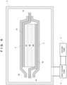
secondary battery 1 according to an example for more specifically describing the aforementioned embodiment is described with reference toFIG. 5 . In the present example, description is given focusing on configurations omitted in the aforementioned embodiment, the same configurations as those in the aforementioned embodiment are denoted by the same reference signs, and description thereof is omitted. - As illustrated in
FIG. 5 ,contents secondary battery 1 according to the present example, that is, what are accommodated in anouter package 2 include anelectrode body 4 and alaminated pack 3 inside of which theelectrode body 4 is hermetically accommodated. Theelectrode body 4 includespowder laminates 47 to 49 formed by laminating layers of powder material andcurrent collectors positive electrode layer 48, anegative electrode layer 47, and asolid electrolyte layer 49 sandwiched between thepositive electrode layer 48 and thenegative electrode layer 47. Thecurrent collectors current collector 4p that is in contact with thepositive electrode layer 48 and a negative electrodecurrent collector 4n that is in contact with thenegative electrode layer 47. The positive electrodecurrent collector 4p and the negative electrodecurrent collector 4n are not completely accommodated in thelaminated pack 3 and theouter package 2, and exposedparts 4e for extracting electric power from the powder laminates 47 to 49 reach the outside of thelaminated pack 3 and theouter package 2. - The
outer package 2 substantially uniformly applies pressing force to each of the front surfaces and the rear surfaces of thecontents outer package 2. Moreover, both the pressure P1 inside thelaminated pack 3 and the pressure P2 inside theouter package 2 and outside thelaminated pack 3 are low to the point of a vacuum, and the relation P1 < P2 is maintained. - More specifically, assuming that the pressure under a vacuum environment under which the
secondary battery 1 according to the present example is used is P', the volume of theouter package 2 in an initial state is V, and the volume of theouter package 2 at the pressure P' is V', selection of theouter package 2 and setting of the pressures P1 and P2 are performed such that following expression (1) is satisfied.
- In the case where the
secondary battery 1 is used under an atmospheric pressure environment, it is preferable that the pressure P2 is also an atmospheric pressure because theelectrode body 4 is sufficiently pressed due to the difference between the respective degrees of vacuum of the inside and outside of thelaminated pack 3. On the other hand, in the case where thesecondary battery 1 is used at the pressure P' under a vacuum environment, it is preferable that the pressure P2 is equal to or less than 1,000 Pa because theelectrode body 4 is sufficiently pressed due to the difference between the respective degrees of vacuum of the inside and outside of thelaminated pack 3. In any of these cases, it is preferable that the pressure P1 is smaller than P2 and is equal to or less than 1 Pa (more preferably, equal to or less than 10-2 Pa) because theelectrode body 4 is sufficiently pressed due to the difference between the respective degrees of vacuum of the inside and outside of thelaminated pack 3. - Hereinafter, a method for manufacturing the
secondary battery 1 is described with reference toFIG. 6 . - Firstly, the
positive electrode layer 48, thesolid electrolyte layer 49, and thenegative electrode layer 47 are formed in the stated order on the positive electrodecurrent collector 4p, and the negative electrodecurrent collector 4n is arranged on thenegative electrode layer 47, whereby theelectrode body 4 is formed. Alternatively, thenegative electrode layer 47, thesolid electrolyte layer 49, and thepositive electrode layer 48 are formed in the stated order on the negative electrodecurrent collector 4n, and the positive electrodecurrent collector 4p is arranged on thepositive electrode layer 48, whereby theelectrode body 4 is formed. Note that, in the case of using an insulating member (resin material) for one of the constituent members of theelectrode body 4, it is preferable to adopt engineering plastic for the insulating member. - It is desirable that the
electrode body 4 is processed such that at least one of (1) the water content value is equal to or less than 500 ppm, (2) the water absorption rate is equal to or less than 0.1%, and (3) the outgassing is equal to or less than 10 µg/cm2 is satisfied. Moreover, it is preferable that theelectrode body 4 is dried at a temperature that is equal to or more than that of a used atmosphere. - Then, this
electrode body 4 is put inside thelaminated pack 3. As illustrated inFIG. 6 , in the state where oneend part 45 of thislaminated pack 3 is not sealed, thelaminated pack 3 is arranged inside a vacuum chamber C. After that, the inside of the vacuum chamber C is brought into a vacuum by suction using a high-vacuum pump H and a vacuum pump V that are connected in series to the vacuum chamber C. When the inside of thelaminated pack 3 reaches the predetermined pressure P1, the oneend part 45 of thelaminated pack 3 is sealed, whereby thecontents - Next, the
outer package 2 for accommodating thecontents outer package 2 has such a shape that can substantially uniformly apply the pressing force to each of the front surfaces and the rear surfaces of the accommodatedcontents FIG. 3 and FIG. 4 . Then, as an accommodation step, thecontents outer package 2. After that, although not illustrated, the inside of theouter package 2 is brought into the predetermined pressure P2 using another vacuum pump or the like, whereby thesecondary battery 1 illustrated inFIG. 5 is manufactured. - In this way, according to the
secondary battery 1 and the method for manufacturing the same according to the present example, because the pressing force is substantially uniformly applied to each of the front surface and the rear surface of theelectrode body 4, the contact resistance inside theelectrode body 4 is decreased, and consequently the battery performance can be further improved. - Moreover, because the elastic force of the
outer package 2 is utilized to substantially uniformly apply the pressing force to each of the front surface and the rear surface of theelectrode body 4, a separate configuration for this pressing force is not necessary, and consequently downsizing can be achieved. - In
FIG. 2 andFIG. 5 for describing the embodiment and example, spaces for describing the pressures P1 and P2 are illustrated. However, these are mere illustrations for easier understanding, and do not mean that such spaces are essential. - Moreover, in
FIG. 5 andFIG. 6 for describing the example, the powder laminates 47 to 49 are illustrated as the structure in which the number of laminated layers in each of thepositive electrode layer 48, thesolid electrolyte layer 49, and thenegative electrode layer 47 is one, but may be more than one. Moreover, inFIG. 5 andFIG. 6 , the number of units of the powder laminates 47 to 49 included in theelectrode body 4 is illustrated as one unit, but may be more than one unit. - Furthermore, in the aforementioned example, as illustrated in
FIG. 6 , the high-vacuum pump H and the vacuum pump V that are connected in series to the vacuum chamber C are described as the apparatus that performs suctioning inside thelaminated pack 3 of thesecondary battery 1, but any apparatus may be adopted as long as the inside of thelaminated pack 3 can be brought into a vacuum. - In addition, the aforementioned embodiment and example are given as mere exemplification in every respect, and the present invention is not limited thereto. The scope of the present invention is defined by not the aforementioned description but Claims, and intends to include meaning equivalent to Claims and all changes within Claims. Among the configurations described in the aforementioned embodiment and example, the configurations other than the configuration that is described as the first aspect of the present invention in "Solution to Problem" are optional configurations, and can be deleted and changed as appropriate.
Claims (6)
- A secondary battery comprising:an outer package; anda content accommodated in the outer package, whereinthe content includes an electrode body, andthe outer package substantially uniformly applies pressing force to each of a front surface and a rear surface of the content due to elastic force of the outer package.
- The secondary battery according to claim 1, wherein the content includes a laminated pack inside of which the electrode body is hermetically accommodated.
- The secondary battery according to claim 2, whereinan inside of the outer package is under a negative pressure, andinside the outer package, an inside of the laminated pack is under a lower pressure than an outside of the laminated pack.
- The secondary battery according to any one of claim 1 to claim 3, wherein the electrode body is formed of powder material.
- A method for manufacturing the secondary battery according to any one of claim 1 to claim 3, the method comprising accommodating the content in the outer package, whereinthe outer package includes a front plate and a rear plate that press and sandwich the accommodated content from the front surface and the rear surface of the accommodated content, andin a state where the content is not accommodated in the outer package,the front plate and the rear plate of the outer package are connected to each other at respective end parts of the front plate and the rear plate by side plates,at least one of the front plate and the rear plate curves toward an inside of the outer package, andthe front plate and the rear plate become closer to each other in central parts of the front plate and the rear plate than in the end parts.
- The method for manufacturing the secondary battery according to claim 5, wherein, in the state where the content is not accommodated in the outer package, one of the front plate and the rear plate of the outer package are parallel to each other in the end parts.
Applications Claiming Priority (1)
| Application Number | Priority Date | Filing Date | Title |
|---|---|---|---|
| PCT/JP2020/035663 WO2022064541A1 (en) | 2020-09-23 | 2020-09-23 | Secondary battery and method for manufacturing same |
Publications (2)
| Publication Number | Publication Date |
|---|---|
| EP4220822A1 true EP4220822A1 (en) | 2023-08-02 |
| EP4220822A4 EP4220822A4 (en) | 2025-04-30 |
Family
ID=80845608
Family Applications (1)
| Application Number | Title | Priority Date | Filing Date |
|---|---|---|---|
| EP20955135.7A Pending EP4220822A4 (en) | 2020-09-23 | 2020-09-23 | Secondary battery and method for producing the same |
Country Status (5)
| Country | Link |
|---|---|
| US (1) | US20230352724A1 (en) |
| EP (1) | EP4220822A4 (en) |
| KR (1) | KR102942317B1 (en) |
| CN (1) | CN116034508A (en) |
| WO (1) | WO2022064541A1 (en) |
Families Citing this family (1)
| Publication number | Priority date | Publication date | Assignee | Title |
|---|---|---|---|---|
| JP7360820B2 (en) * | 2019-05-30 | 2023-10-13 | 日立造船株式会社 | Secondary battery and its manufacturing method |
Family Cites Families (13)
| Publication number | Priority date | Publication date | Assignee | Title |
|---|---|---|---|---|
| JPH09120836A (en) | 1995-10-24 | 1997-05-06 | Seiko Instr Inc | Non-aqueous electrolyte secondary battery and method of manufacturing the same |
| JP3071990U (en) * | 2000-03-24 | 2000-09-29 | パイオニクス株式会社 | Outer case for polymer secondary battery |
| JP2005197179A (en) * | 2004-01-09 | 2005-07-21 | Toyota Motor Corp | Single cells and batteries |
| KR20110049864A (en) * | 2009-02-05 | 2011-05-12 | 파나소닉 주식회사 | Secondary battery, battery pack with secondary battery, and method of manufacturing secondary battery |
| JP5625834B2 (en) | 2010-12-02 | 2014-11-19 | 日産自動車株式会社 | Assembled battery |
| JP2014238912A (en) * | 2011-09-28 | 2014-12-18 | パナソニック株式会社 | Battery pack and manufacturing method thereof |
| JP5851785B2 (en) * | 2011-09-29 | 2016-02-03 | オートモーティブエナジーサプライ株式会社 | Battery and manufacturing method thereof |
| JP2014010916A (en) * | 2012-06-27 | 2014-01-20 | Sharp Corp | Secondary battery |
| JP2014103055A (en) * | 2012-11-22 | 2014-06-05 | Nissan Motor Co Ltd | Battery pack |
| CN107735881B (en) * | 2015-07-01 | 2019-07-30 | 日产自动车株式会社 | flat battery |
| EP3428992B1 (en) * | 2016-03-10 | 2020-04-29 | Nissan Motor Co., Ltd. | Battery pack |
| JP6852328B2 (en) * | 2016-09-20 | 2021-03-31 | 株式会社Gsユアサ | Power storage device and manufacturing method of power storage device |
| CN109906526A (en) * | 2017-01-31 | 2019-06-18 | 松下知识产权经营株式会社 | Secondary cell |
-
2020
- 2020-09-23 US US18/245,379 patent/US20230352724A1/en active Pending
- 2020-09-23 KR KR1020237008021A patent/KR102942317B1/en active Active
- 2020-09-23 EP EP20955135.7A patent/EP4220822A4/en active Pending
- 2020-09-23 WO PCT/JP2020/035663 patent/WO2022064541A1/en not_active Ceased
- 2020-09-23 CN CN202080105158.9A patent/CN116034508A/en active Pending
Also Published As
| Publication number | Publication date |
|---|---|
| US20230352724A1 (en) | 2023-11-02 |
| KR102942317B1 (en) | 2026-03-19 |
| WO2022064541A1 (en) | 2022-03-31 |
| CN116034508A (en) | 2023-04-28 |
| EP4220822A4 (en) | 2025-04-30 |
| KR20230074122A (en) | 2023-05-26 |
Similar Documents
| Publication | Publication Date | Title |
|---|---|---|
| US12051823B2 (en) | Pouch-shaped battery case comprising crack prevention structure and method of manufacturing the same | |
| JP6960271B2 (en) | All solid state battery | |
| US11335941B2 (en) | Apparatus and method for manufacturing battery cell | |
| KR102075618B1 (en) | Pouch type secondary battery and Apparatus for forming Pouch film | |
| US20150140371A1 (en) | Curved battery container | |
| CN106654141B (en) | Electrolyte wetting enhancement equipment and electrolyte wetting enhancement method using the same | |
| KR102004295B1 (en) | Manufacturing method of secondary battery | |
| KR100804522B1 (en) | Manufacturing method of secondary battery | |
| JP2019061861A (en) | All solid battery and method of manufacturing the same | |
| GB2579964A8 (en) | Pouch battery or cell | |
| JP6868871B2 (en) | Secondary battery and its manufacturing method | |
| KR20190101650A (en) | Capacity recovering method for secondary battery and capacity recovering device for secondary battery | |
| EP4167330B1 (en) | Secondary battery and method for manufacturing the same | |
| US20230352724A1 (en) | Secondary battery and method for manufacturing same | |
| KR20170094669A (en) | Method and apparatus for manufacturing of prismatic secondary battery | |
| US20240021880A1 (en) | Battery, battery system and battery manufacturing method | |
| JPH0513054A (en) | Sealed rectangular storage battery and manufacture thereof | |
| CN220021204U (en) | A solid-state battery cell | |
| EP4726824A1 (en) | Method for isostatically pressing electrode assembly using protection member as outer sacrificial frame, and all-solid-state battery including protection member | |
| JP2003242938A (en) | Sealed rectangular storage battery and method of manufacturing the same | |
| KR100473401B1 (en) | Producing method of lithium polymer secondary battery | |
| CN118173855A (en) | Battery packaging method and packaged battery | |
| JP2024162701A (en) | Ultra-large capacity solid polymer lithium ion battery and its manufacturing method | |
| JP2002298798A (en) | Battery, electric double layer capacitor, method of manufacturing battery, and method of manufacturing electric double layer capacitor |
Legal Events
| Date | Code | Title | Description |
|---|---|---|---|
| STAA | Information on the status of an ep patent application or granted ep patent |
Free format text: STATUS: THE INTERNATIONAL PUBLICATION HAS BEEN MADE |
|
| PUAI | Public reference made under article 153(3) epc to a published international application that has entered the european phase |
Free format text: ORIGINAL CODE: 0009012 |
|
| STAA | Information on the status of an ep patent application or granted ep patent |
Free format text: STATUS: REQUEST FOR EXAMINATION WAS MADE |
|
| 17P | Request for examination filed |
Effective date: 20230418 |
|
| AK | Designated contracting states |
Kind code of ref document: A1 Designated state(s): AL AT BE BG CH CY CZ DE DK EE ES FI FR GB GR HR HU IE IS IT LI LT LU LV MC MK MT NL NO PL PT RO RS SE SI SK SM TR |
|
| DAV | Request for validation of the european patent (deleted) | ||
| DAX | Request for extension of the european patent (deleted) | ||
| A4 | Supplementary search report drawn up and despatched |
Effective date: 20250402 |
|
| RIC1 | Information provided on ipc code assigned before grant |
Ipc: H01M 50/10 20210101AFI20250327BHEP |
|
| RAP3 | Party data changed (applicant data changed or rights of an application transferred) |
Owner name: KANADEVIA CORPORATION Owner name: OHKITA SEISAKUSYO |