EP4220195B1 - Single-phase electric energy metering chip capable of anti-tampering with neutral missing - Google Patents
Single-phase electric energy metering chip capable of anti-tampering with neutral missing Download PDFInfo
- Publication number
- EP4220195B1 EP4220195B1 EP22730043.1A EP22730043A EP4220195B1 EP 4220195 B1 EP4220195 B1 EP 4220195B1 EP 22730043 A EP22730043 A EP 22730043A EP 4220195 B1 EP4220195 B1 EP 4220195B1
- Authority
- EP
- European Patent Office
- Prior art keywords
- circuit
- neutral
- tampering
- missing
- electric energy
- Prior art date
- Legal status (The legal status is an assumption and is not a legal conclusion. Google has not performed a legal analysis and makes no representation as to the accuracy of the status listed.)
- Active
Links
Images



Classifications
-
- G—PHYSICS
- G01—MEASURING; TESTING
- G01R—MEASURING ELECTRIC VARIABLES; MEASURING MAGNETIC VARIABLES
- G01R22/00—Arrangements for measuring time integral of electric power or current, e.g. electricity meters
- G01R22/06—Arrangements for measuring time integral of electric power or current, e.g. electricity meters by electronic methods
- G01R22/061—Details of electronic electricity meters
- G01R22/066—Arrangements for avoiding or indicating fraudulent use
-
- G—PHYSICS
- G01—MEASURING; TESTING
- G01R—MEASURING ELECTRIC VARIABLES; MEASURING MAGNETIC VARIABLES
- G01R21/00—Arrangements for measuring electric power or power factor
- G01R21/133—Arrangements for measuring electric power or power factor by using digital technique
-
- G—PHYSICS
- G01—MEASURING; TESTING
- G01R—MEASURING ELECTRIC VARIABLES; MEASURING MAGNETIC VARIABLES
- G01R11/00—Electromechanical arrangements for measuring time integral of electric power or current, e.g. of consumption
- G01R11/02—Constructional details
- G01R11/24—Arrangements for avoiding or indicating fraudulent use
-
- Y—GENERAL TAGGING OF NEW TECHNOLOGICAL DEVELOPMENTS; GENERAL TAGGING OF CROSS-SECTIONAL TECHNOLOGIES SPANNING OVER SEVERAL SECTIONS OF THE IPC; TECHNICAL SUBJECTS COVERED BY FORMER USPC CROSS-REFERENCE ART COLLECTIONS [XRACs] AND DIGESTS
- Y04—INFORMATION OR COMMUNICATION TECHNOLOGIES HAVING AN IMPACT ON OTHER TECHNOLOGY AREAS
- Y04S—SYSTEMS INTEGRATING TECHNOLOGIES RELATED TO POWER NETWORK OPERATION, COMMUNICATION OR INFORMATION TECHNOLOGIES FOR IMPROVING THE ELECTRICAL POWER GENERATION, TRANSMISSION, DISTRIBUTION, MANAGEMENT OR USAGE, i.e. SMART GRIDS
- Y04S20/00—Management or operation of end-user stationary applications or the last stages of power distribution; Controlling, monitoring or operating thereof
- Y04S20/20—End-user application control systems
Definitions
- the present invention belongs to the field of electric power, and more particularly, to a single-phase electric energy metering chip capable of realizing anti-tampering with neutral missing.
- Anti-tampering with neutral missing is a common way to steal electricity, in which a user usually removes a neutral wire (N) connected to an electric energy meter. In this case, the electric energy meter cannot work because there is no power supply, and there is no a voltage signal but only a current signal, so the electric energy meter cannot measure the electric energy normally.
- Metering of anti-tampering with neutral missing is a way of preventing electricity stealing which uses a battery or a PT (Potential Transformer) as a standby power supply and uses a current effective value for measurement when the user steals electricity by dropping the neutral wire. When the PT is used as the standby power supply, the PT is used to obtain a power supply from a current sampling loop.
- an electric energy metering SOC System On Chip
- the electric energy metering SOC is a chip that integrates a power metering module and a MCU (Microcontroller Unit).
- the metering of anti-tampering with neutral missing is mainly realized by a metering module in the SOC, while functions of the electric energy meter are completed by the MCU.
- a metering module in the SOC With the development of electric energy meter technologies, users have more and more function demands on the electric energy meters, and meanwhile, the demands are more and more diversified. Therefore, the demands on the MCU are becoming diversified and high-end. However, there is no obvious change in preventing electricity stealing. Because the SOC integrates the metering module and the MCU on one chip, independent combination of metering electricity stealing prevention and multiple MCUs cannot be realized.
- a more advanced manufacturing process may be adopted for a digital part of the MCU to reduce a wafer area, thus reducing the cost, while the metering part is mainly an analog circuit. Considering the reliability and metering accuracy, it is impossible to adopt a more advanced manufacturing process. Due to this limitation, the manufacturing cost of the electric energy metering SOC cannot be reduced.
- the technical problem to be solved by the present invention is to provide a single-phase electric energy metering chip capable of realizing anti-tampering with neutral missing aiming at the deficiencies of the prior art.
- the present invention discloses a single-phase electric energy metering chip capable of realizing anti-tampering with neutral missing, comprising a working mode control circuit, an ADC sampling circuit, a current effective value measuring circuit, a judgment circuit for anti-tampering with neutral missing, an electric energy metering circuit and a clock circuit, wherein:
- the working mode comprises a normal metering mode, a low power consumption standby mode, a timed wake-up working mode and a metering mode of anti-tampering with neutral missing; when the main power supply is powered on, the single-phase electric energy metering chip enters the normal metering mode; and when the main power supply is not powered on, the single-phase electric energy metering chip enters the low power consumption standby mode, and under the low power consumption standby mode, the ADC sampling circuit, the current effective value measuring circuit and the judgment circuit for anti-tampering with neutral missing are in standby state, and the electric energy metering circuit is in a standby state or working state.
- the working mode control circuit comprises a working mode control pin, a control pin monitoring circuit, a low power consumption timer and a working mode switching circuit,
- running power consumption of the metering chip mainly comes from standby power consumption, instantaneous average power consumption during timed wake-up working, and power consumption of metering of anti-tampering with neutral missing.
- the single-phase electric energy metering chip is in the low power consumption standby mode most of the time, so the power consumption of the standby circuit in the working mode switching circuit needs to be as small as possible (recommended maximum power consumption is ⁇ 2 uA), and the design should be as simple as possible.
- the switching among the low power consumption standby mode, the timed wake-up working mode and the metering mode of anti-tampering with neutral missing comprises:
- the pre-judging, by the judgment circuit for anti-tampering with neutral missing, the digital signal to judge whether the current loop has a current in step 3 comprises:
- the performing, by the electric energy metering circuit, energy accumulation calculation on the current effective value to obtain the energy pulse in step 6 comprises:
- the electric energy metering circuit adopts a low frequency clock as the clock source.
- the clock circuit comprises a low frequency clock signal input pin, a PLL (Phase Locked Loop) circuit, a clock selection circuit, a first frequency dividing circuit, a second frequency dividing circuit, a third frequency dividing circuit and a fourth frequency dividing circuit.
- PLL Phase Locked Loop
- An input end of the low frequency clock signal input pin inputs a low frequency clock, a first output end of the low frequency clock signal input pin is connected with a low power consumption standby circuit, a second output end of the low frequency clock signal input pin is connected with a first input end of the clock selection circuit, and a third output end of the low frequency clock signal input pin is connected with an input end of the PLL circuit.
- a first output end of the PLL circuit is connected with an input end of the first frequency dividing circuit
- a second output end of the PLL circuit is connected with an input end of the second frequency dividing circuit
- a third output end of the PLL circuit is connected with an input end of the third frequency dividing circuit
- a fourth output end of the PLL circuit is connected with an input end of the fourth frequency dividing circuit; the PLL circuit multiplies the low frequency clock to the high frequency clock, and clock output frequencies of each output end of the PLL circuit may be designed by each chip design company according to high frequency clock input of an original metering chip thereof.
- An output end of the first frequency dividing circuit is connected with the ADC sampling circuit, an output end of the second frequency dividing circuit is connected with the judgment circuit for anti-tampering with neutral missing, an output end of the third frequency dividing circuit is connected with the current effective value measuring circuit, and an output end of the fourth frequency dividing circuit is connected with a second input end of the clock selection circuit; and an output end of the clock selection circuit is connected with the electric energy metering circuit, when the working mode of the single-phase electric energy metering chip is the normal metering mode, the clock selection circuit outputs the high frequency clock, and when the working mode of the single-phase electric energy metering chip is the metering mode of anti-tampering with neutral missing, the clock selection circuit outputs the low frequency clock.
- the clock circuit comprises a communication port, a clock correction circuit, a low frequency oscillating circuit, a high frequency oscillating circuit, a clock selection circuit, a first frequency dividing circuit, a second frequency dividing circuit, a third frequency dividing circuit and a fourth frequency dividing circuit,
- An output end of the first frequency dividing circuit is connected with the ADC sampling circuit, an output end of the second frequency dividing circuit is connected with the judgment circuit for anti-tampering with neutral missing, an output end of the third frequency dividing circuit is connected with the current effective value measuring circuit, and an output end of the fourth frequency dividing circuit is connected with a second input end of the clock selection circuit; and an output end of the clock selection circuit is connected with the electric energy metering circuit, when the working mode of the single-phase electric energy metering chip is the normal metering mode, the clock selection circuit outputs the high frequency clock, and when the working mode of the single-phase electric energy metering chip is the metering mode of anti-tampering with neutral missing, the clock selection circuit outputs the low frequency clock.
- the clock selection circuit is added to the above two clock circuits, and the clock selection circuit comprises a low frequency clock option. In this way, when performing metering of anti-tampering with neutral missing, the clock of the energy metering circuit only needs to be switched to a low frequency clock, and it is not necessary to design an energy metering circuit for anti-tampering with neutral missing specially.
- the preset parameters in step 1 further comprise a measuring object of the current effective value measuring circuit, and the measuring object comprises simultaneous measurement of two current effective values of a live wire and a neutral wire, or measurement of either the current effective value of the live wire or the current effective value of the neutral wire; when the simultaneous measurement of the two current effective values of the live wire and the neutral wire is selected as the measuring object, after the waking up the current effective value measuring circuit to measure the current effective value in step 4, a large current effective value is selected to perform step 5 and step 6; and if the current loop has a current in step 4, the current effective value measuring circuit is waken up to measure the current effective value after waiting for a time T1; and after the current effective value is measured, an ADC module and the current effective value measuring circuit enter the standby state.
- the present application provides the novel single-phase electric energy metering chip with the metering function of anti-tampering with neutral missing, which integrates the metering function of anti-tampering with neutral missing into the metering chip.
- a MCU does not need to participate in the metering of electricity stealing prevention in the whole process of anti-tampering with neutral missing, but only needs to obtain the electric energy data through an external wake-up interrupt interface, thus greatly simplifying the design of neutral-wire electricity stealing prevention in the MCU and reducing the power consumption of anti-tampering with neutral missing, and allowing an electric energy meter designer to design a more competitive electric energy meter for anti-tampering with neutral missing based on the single-phase electric energy metering chip.
- a design block diagram of a MCU plus a single-phase metering chip to realize metering of anti-tampering with neutral missing at present is as shown in FIG. 1 .
- a main power supply is a power supply when an electric energy meter works normally, and when a neutral wire is connected to the electric energy meter normally, a MCU is powered by the main power supply. When the neutral wire is dropped, the MCU is powered by another power supply (from a battery or a dedicated power supply PT).
- a power supply of a metering chip is controlled by the MCU.
- a main power supply monitoring circuit monitors that the electric energy meter is in a state of anti-tampering with neutral missing
- the MCU turns off the power supply of the metering chip, and enters a low power consumption working state at the same time.
- the MCU will wake up regularly and turn on the power supply of the metering chip, then initialize the metering chip through a communication interface, enable effective value measurement, read a current effective value after a period of time, and turn off the power supply of the metering chip.
- the MCU calculates an electric energy according to the current effective value, and generates an energy pulse (CF, Calibration Frequency). The above operation will be repeated periodically until the main power supply is powered on.
- CF Calibration Frequency
- the existing MCU plus the metering chip for anti-tampering with neutral missing needs the MCU to wake up and control the metering chip constantly, and also needs the MCU to realize energy accumulation and output of energy pulse at the same time, which is not only complicated, but also difficult to achieve low power consumption. If low power consumption cannot be achieved, the cost of the overall solution will be uncompetitive.
- the metering function of anti-tampering with neutral missing above is integrated into the metering chip, and the MCU does not need to participate in metering of electricity stealing prevention in the whole process of anti-tampering with neutral missing, but only needs to obtain the electric energy data through an external wake-up interrupt interface, thus greatly simplifying the design of anti-tampering with neutral missing and reducing the power consumption of anti-tampering with neutral missing.
- This embodiment discloses a single-phase electric energy metering chip capable of realizing anti-tampering with neutral missing, as shown in FIG. 2 , comprising a working mode control circuit, an ADC sampling circuit, a current effective value measuring circuit, a judgment circuit for anti-tampering with neutral missing, an electric energy metering circuit and a clock circuit.
- a working mode control circuit comprising a working mode control circuit, an ADC sampling circuit, a current effective value measuring circuit, a judgment circuit for anti-tampering with neutral missing, an electric energy metering circuit and a clock circuit.
- the working mode control circuit is configured for being connected to a main control chip, receiving a control signal which is configured for judging whether a main power supply is powered on and sent by the main control chip, and selecting a working mode of the single-phase electric energy metering chip according to the result whether the main power supply is powered on;
- the working mode comprises a normal metering mode, a low power consumption standby mode, a timed wake-up working mode and a metering mode of anti-tampering with neutral missing.
- a control pin inputs a low level and the single-phase electric energy metering chip enters the normal metering mode; and when the main power supply is not powered on, like the working mode shown in FIG.
- the control outputs a high level
- the single-phase electric energy metering chip enters the low power consumption standby mode
- the ADC sampling circuit the current effective value measuring circuit and the judgment circuit for anti-tampering with neutral missing are in standby state
- the electric energy metering circuit is in a standby state or working state.
- the level description of the operating mode control pin in FIG. 5 is for illustration only, and an opposite logic may also be adopted during actual implementation.
- the main control chip When switching from other modes to the normal metering mode, the main control chip first reads energy data from the single-phase electric energy metering chip, and then the single-phase electric energy metering chip reinitializes and reconfigures various parameters comprising the preset parameters.
- the working mode control circuit comprises a working mode control pin, a control pin monitoring circuit, a low power consumption timer and a working mode switching circuit.
- the working mode control pin is configured for being connected to the main control chip and receiving the control signal sent by the main control chip.
- the control pin monitoring circuit is configured for monitoring the control signal, wherein when the main power supply is powered on, the single-phase electric energy metering chip enters the normal metering mode, and when the main power supply is not powered on, the single-phase electric energy metering chip enters the low power consumption standby mode.
- internal analog or digital filtering is performed in the control pin monitoring circuit, and the internal analog may be capacitive filtering or RC filtering.
- a recommended filtering width is 10 ms, and a level duration exceeds 10 ms, which can be regarded as an effective control signal.
- the low power consumption timer is configured for monitoring whether a timed wake-up period T is reached in the low power consumption standby mode, and waking up the single-phase electric energy metering chip to enter the timed wake-up working mode when the timed wake-up period T is reached; and the clock circuit provides a low frequency clock source for the low power consumption timer and the clock is a low-speed clock of 32,768 Hz. In order to further reduce the power consumption, the clock may also subject to frequency division.
- the working mode switching circuit is configured for switching among the low power consumption standby mode, the timed wake-up working mode and the metering mode of anti-tampering with neutral missing.
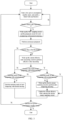
- FIG. 3 and FIG. 4 A flow chart of switching among the low power consumption standby mode, the timed wake-up working mode and the metering mode of anti-tampering with neutral missing is as shown in FIG. 3 and FIG. 4 , comprising:
- the timed wake-up working mode and the low power consumption standby mode also exist at the same time.
- the electric energy metering circuit is enabled (in this case, the metering of anti-tampering with neutral missing is performed, and the low frequency clock is adopted to reduce the power consumption), and the electric energy metering circuit keeps working after being enabled.
- the single-phase electric energy metering chip enters the low power consumption standby mode again to repeat step 2, and enters the timed wake-up working mode again when reaching the timed wake-up period T, and executes step 3 to step 5 to make judgment on anti-tampering with neutral missing; if the newly measured current effective value exceeds the threshold of anti-tampering with neutral missing, the newly measured current effective value is given to the electric energy metering circuit; if the newly measured current effective value is below the threshold of anti-tampering with neutral missing, the electric energy metering circuit enters the standby state, and then enters the low power consumption standby mode again.
- the pre-judging, by the judgment circuit for anti-tampering with neutral missing, the digital signal to judge whether the current loop has a current in step 3 comprises:
- a power grid frequency is usually 50 Hz
- n of sampling points with present sampling values exceeding the first threshold V is 16, in the half cycle sampling period of 10 ms, if the sampling values of more than 16 sampling points in 64 sampling points are greater than the first threshold V, it is considered that the current loop has a current, such as n1 in FIG. 8 ; and if the sampling values of less than 16 sampling points are greater than the first threshold V, it is considered that the current loop has no current, such as n2 in FIG. 8 .
- the pre-judgment accuracy is not high, the results are output quickly, and judgment can be made basically in half cycle.
- the first threshold and the threshold of anti-tampering with neutral missing above may be set in step 1.
- the performing, by the electric energy metering circuit, energy accumulation calculation on the current effective value to obtain the energy pulse in step 6, is as shown in FIG. 4 , comprising:
- Energy pulse is an output mode of electric energy commonly used in the electric energy metering chips, which is related to a pulse constant on a nameplate of the electric energy meter.
- the electric energy metering circuit adopts a low frequency clock as the clock source.
- the electric energy metering circuit adopts a high frequency clock as the clock source.
- the clock circuit may be implemented in the following ways, comprising, but not limited to: as shown in FIG. 6 , in the first implementation manner, the clock circuit comprises a low frequency clock signal input pin 1, a PLL circuit, a clock selection circuit, a first frequency dividing circuit, a second frequency dividing circuit, a third frequency dividing circuit and a fourth frequency dividing circuit, and there are also other circuits in the clock circuit of the single-phase electric energy metering chip, which belong to the prior art, and are not limited in the embodiment of the present invention here.
- An input end of the low frequency clock signal input pin 1 inputs a low frequency clock, a first output end of the low frequency clock signal input pin 1 is connected with a low power consumption standby circuit, a second output end of the low frequency clock signal input pin 1 is connected with a first input end of the clock selection circuit, and a third output end of the low frequency clock signal input pin 1 is connected with an input end of the PLL circuit; when a low frequency clock is input to the input end of the low frequency clock signal input pin 1, a low frequency crystal oscillator (generally a crystal oscillator of 32,768 Hz) may be externally connected, or a clock signal of 32,768 Hz may be directly input.
- a low frequency crystal oscillator generally a crystal oscillator of 32,768 Hz
- a clock signal of 32,768 Hz may be directly input.
- a first output end of the PLL circuit is connected with an input end of the first frequency dividing circuit, a second output end of the PLL circuit is connected with an input end of the second frequency dividing circuit, a third output end of the PLL circuit is connected with an input end of the third frequency dividing circuit, and a fourth output end of the PLL circuit is connected with an input end of the fourth frequency dividing circuit;
- the clock circuit comprises a communication port 2, a clock correction circuit, a low frequency oscillating circuit, a high frequency oscillating circuit, a clock selection circuit, a first frequency dividing circuit, a second frequency dividing circuit, a third frequency dividing circuit and a fourth frequency dividing circuit.
- An input end of the communication port 2 inputs training bytes sent by the main control chip, an output end of the communication port 2 is connected with an input end of the clock correction circuit, a first output end of the clock correction circuit is connected with an input end of the low frequency oscillating circuit, and a second output end of the clock correction circuit is connected with an input end of the high frequency oscillating circuit.
- the communication port 2 is a direct communication interface between the single-phase electric energy metering chip and the main control chip MCU, which comes with the single-phase electric energy metering chip, and is generally a UART (Universal Asynchronous Receiver/Transmitter) interface, but through a special frame header design, the single-phase electric energy metering chip may also use this communication interface to correct clocks of the internal high frequency oscillating circuit RCH (high frequency oscillating circuit composed of a resistor R and a capacitor C) and the low frequency oscillating circuit RCL (low frequency oscillating circuit composed of a resistor R and a capacitor C).
- RCH high frequency oscillating circuit composed of a resistor R and a capacitor C
- RCL low frequency oscillating circuit composed of a resistor R and a capacitor C
- a first output end of the low frequency oscillating circuit is connected with the low power consumption standby circuit, and an second output end of the low frequency oscillating circuit is connected with the first input end of the clock selection circuit;
- the preset parameters in step 1 further comprise a measuring object of the current effective value measuring circuit, and the measuring object comprises simultaneous measurement of two current effective values of a live wire and a neutral wire, or measurement of either the current effective value of the live wire or the current effective value of the neutral wire; when the simultaneous measurement of the two current effective values of the live wire and the neutral wire is selected as the measuring object, after the waking up the current effective value measuring circuit to measure the current effective value in step 4, a large current effective value is selected to perform step 5 and step 6; and if the current loop has a current in step 4, the current effective value measuring circuit is waken up to measure the current effective value after waiting for a time T1, wherein the time T1 is usually 10 ms; and after the current effective value is measured, an ADC module and the current effective value measuring circuit enter the standby state.
- the present invention provides an idea and a method for the single-phase electric energy metering chip capable of realizing anti-tampering with neutral missing.
Landscapes
- Physics & Mathematics (AREA)
- General Physics & Mathematics (AREA)
- Engineering & Computer Science (AREA)
- Power Engineering (AREA)
- Measurement Of Current Or Voltage (AREA)
- Electric Clocks (AREA)
Description
- The present invention belongs to the field of electric power, and more particularly, to a single-phase electric energy metering chip capable of realizing anti-tampering with neutral missing.
- Anti-tampering with neutral missing is a common way to steal electricity, in which a user usually removes a neutral wire (N) connected to an electric energy meter. In this case, the electric energy meter cannot work because there is no power supply, and there is no a voltage signal but only a current signal, so the electric energy meter cannot measure the electric energy normally. Metering of anti-tampering with neutral missing is a way of preventing electricity stealing which uses a battery or a PT (Potential Transformer) as a standby power supply and uses a current effective value for measurement when the user steals electricity by dropping the neutral wire. When the PT is used as the standby power supply, the PT is used to obtain a power supply from a current sampling loop.
- There are many ways to realize metering of anti-tampering with neutral missing. In the field of metering of anti-tampering with neutral missing, due to the consideration of cost and power consumption, an electric energy metering SOC (System On Chip) is usually used to realize the metering of anti-tampering with neutral missing. The electric energy metering SOC is a chip that integrates a power metering module and a MCU (Microcontroller Unit). With the development of technology, the limitation of using the SOC to realize the metering of anti-tampering with neutral missing is becoming more and more obvious. The main reasons are as follows.
- The metering of anti-tampering with neutral missing is mainly realized by a metering module in the SOC, while functions of the electric energy meter are completed by the MCU. With the development of electric energy meter technologies, users have more and more function demands on the electric energy meters, and meanwhile, the demands are more and more diversified. Therefore, the demands on the MCU are becoming diversified and high-end. However, there is no obvious change in preventing electricity stealing. Because the SOC integrates the metering module and the MCU on one chip, independent combination of metering electricity stealing prevention and multiple MCUs cannot be realized. Secondly, a more advanced manufacturing process may be adopted for a digital part of the MCU to reduce a wafer area, thus reducing the cost, while the metering part is mainly an analog circuit. Considering the reliability and metering accuracy, it is impossible to adopt a more advanced manufacturing process. Due to this limitation, the manufacturing cost of the electric energy metering SOC cannot be reduced.
- Considering the market demands and design cost, it is a trend to adopt a MCU plus a single-phase metering chip to realize metering of anti-tampering with neutral missing, but there is still no single-phase metering chip on the market to better meet the above market demands at present.
- Examples of the state of the art include the following:
- Analog Devices, "Energy Metering IC with On-Chip Fault and Missing Neutral Detection ADE7761A", (20060101), URL: https://www.analog.com/media/en/technical-documentation/data-sheets/ADE7761A pdf; and
Texas Instruments, "One-Phase Shunt Electricity Meter Reference Design Using Standalone ADCs Description", (20210201), URL: https://www.ti.com/lit/ug/tiduem7a/tiduem7a.pdf?ts=1689752988955, (2023071 8). - Object of the present invention: the technical problem to be solved by the present invention is to provide a single-phase electric energy metering chip capable of realizing anti-tampering with neutral missing aiming at the deficiencies of the prior art.
- In order to solve the foregoing technical problem, the present invention discloses a single-phase electric energy metering chip capable of realizing anti-tampering with neutral missing, comprising a working mode control circuit, an ADC sampling circuit, a current effective value measuring circuit, a judgment circuit for anti-tampering with neutral missing, an electric energy metering circuit and a clock circuit, wherein:
- the working mode control circuit is configured for being connected to a main control chip, receiving a control signal which is configured for judging whether a main power supply is powered on and sent by the main control chip, and selecting a working mode of the single-phase electric energy metering chip according to the result whether the main power supply is powered on;
- the ADC sampling circuit is configured for sampling a current signal to obtain a digital signal;
- the current effective value measuring circuit is configured for measuring a current effective value;
- the judgment circuit for anti-tampering with neutral missing is configured for prejudging the digital signal to judge whether a current loop has a current, and if the current loop has a current, accurately judging the current effective value; and if the current effective value exceeds a threshold of anti-tampering with neutral missing, judging that it is necessary to perform metering of anti-tampering with neutral missing;
- the electric energy metering circuit is configured for performing energy calculation on the current effective value to obtain an energy pulse; and
- the clock circuit is configured for providing a clock source for the working mode control circuit, the ADC sampling circuit, the current effective value measurement circuit, the judgment circuit for anti-tampering with neutral missing and the electric energy metering circuit.
- Further, the working mode comprises a normal metering mode, a low power consumption standby mode, a timed wake-up working mode and a metering mode of anti-tampering with neutral missing; when the main power supply is powered on, the single-phase electric energy metering chip enters the normal metering mode; and when the main power supply is not powered on, the single-phase electric energy metering chip enters the low power consumption standby mode, and under the low power consumption standby mode, the ADC sampling circuit, the current effective value measuring circuit and the judgment circuit for anti-tampering with neutral missing are in standby state, and the electric energy metering circuit is in a standby state or working state.
- Further, the working mode control circuit comprises a working mode control pin, a control pin monitoring circuit, a low power consumption timer and a working mode switching circuit,
- the working mode control pin is configured for being connected to the main control chip and receiving the control signal sent by the main control chip;
- the control pin monitoring circuit is configured for monitoring the control signal, wherein when the main power supply is powered on, the single-phase electric energy metering chip enters the normal metering mode, and when the main power supply is not powered on, the single-phase electric energy metering chip enters the low power consumption standby mode;
- the low power consumption timer is configured for monitoring whether a timed wake-up period T is reached in the low power consumption standby mode, and waking up the single-phase electric energy metering chip to enter the timed wake-up working mode when the timed wake-up period T is reached; and the clock circuit provides a low frequency clock source for the low power consumption timer; and
- the working mode switching circuit is configured for switching among the low power consumption standby mode, the timed wake-up working mode and the metering mode of anti-tampering with neutral missing.
- When metering anti-tampering with neutral missing, running power consumption of the metering chip mainly comes from standby power consumption, instantaneous average power consumption during timed wake-up working, and power consumption of metering of anti-tampering with neutral missing. The single-phase electric energy metering chip is in the low power consumption standby mode most of the time, so the power consumption of the standby circuit in the working mode switching circuit needs to be as small as possible (recommended maximum power consumption is < 2 uA), and the design should be as simple as possible.
- Further, the switching among the low power consumption standby mode, the timed wake-up working mode and the metering mode of anti-tampering with neutral missing comprises:
- step 1: configuring, by the main control chip, preset parameters, wherein the preset parameters comprise:
- the timed wake-up period T for switching from the low power consumption standby mode to the timed wake-up working mode; and
- a working clock frequency of the ADC sampling circuit, a working clock frequency of the judgment circuit for anti-tampering with neutral missing, a working clock frequency of the current effective value measuring circuit and a working clock frequency of the electric energy metering circuit after entering the timed wake-up working mode;
- step 2: entering, by the single-phase electric energy metering chip, the timed wake-up working mode to wake up the ADC sampling circuit and the judgment circuit for anti-tampering with neutral missing under the low power consumption standby mode when the timed wake-up period T is reached;
- step 3: sampling, by the ADC sampling circuit, the current signal to obtain the digital signal; and pre-judging, by the judgment circuit for anti-tampering with neutral missing, the digital signal to judge whether the current loop has a current;
- step 4: if the current loop does not have a current, quitting the timed wake-up working mode and re-entering the low power consumption standby mode; and if the current loop has a current, waking up the current effective value measuring circuit to measure the current effective value;
- step 5: accurately judging, by the judgment circuit for anti-tampering with neutral missing, the current effective value, if the current effective value is below the threshold of anti-tampering with neutral missing, and the single-phase electric energy metering chip is also in the metering mode of anti-tampering with neutral missing at the moment, entering, by the electric energy metering circuit, the standby state, quitting the metering mode of anti-tampering with neutral missing and the timed wake-up working mode, and entering the low power consumption standby mode; if the single-phase electric energy metering chip is not in the metering mode of anti-tampering with neutral missing at the moment, quitting the timed wake-up working mode and entering the low power consumption standby mode; and after entering the low power consumption standby mode, repeating step 2; and
if the current effective value exceeds the threshold of anti-tampering with neutral missing, and the single-phase electric energy metering chip is in the metering mode of anti-tampering with neutral missing, performing step 6; otherwise, waking up the electric energy metering circuit to enter the metering mode of anti-tampering with neutral missing to perform 6; and - step 6: performing, by the electric energy metering circuit, energy accumulation calculation on the current effective value to obtain the energy pulse; and keeping, by the single-phase electric energy metering chip, the metering mode of anti-tampering with neutral missing, which means that the electric energy metering circuit being in the working mode and the single-phase electric energy metering chip entering the low power consumption standby mode at the same time, and repeating step 2.
- Further, the pre-judging, by the judgment circuit for anti-tampering with neutral missing, the digital signal to judge whether the current loop has a current in step 3 comprises:
- if sampling values of more than n continuous sampling points of the digital signal exceed a first threshold V within half cycle time, determining that a current passes through the current loop; otherwise, determining that no current passes through the current loop, wherein a value of n is set according to a number N of sampling points of the digital signal within one cycle time and the first threshold value V, and usually in a value range of N/4 to N/8; and
- adopting, by the judgment circuit for anti-tampering with neutral missing, a high frequency clock as the clock source.
- Further, the performing, by the electric energy metering circuit, energy accumulation calculation on the current effective value to obtain the energy pulse in step 6 comprises:
- step 6.1: performing energy accumulation calculation on the current effective value to obtain energy data; and
- step 6.2: judging whether the energy data reach a pulse threshold THCF, and if the energy data do not reach the pulse threshold THCF, continuing step 6.1; and
- Further, in the metering mode of anti-tampering with neutral missing in step 6, the electric energy metering circuit adopts a low frequency clock as the clock source.
- Further, the clock circuit comprises a low frequency clock signal input pin, a PLL (Phase Locked Loop) circuit, a clock selection circuit, a first frequency dividing circuit, a second frequency dividing circuit, a third frequency dividing circuit and a fourth frequency dividing circuit.
- An input end of the low frequency clock signal input pin inputs a low frequency clock, a first output end of the low frequency clock signal input pin is connected with a low power consumption standby circuit, a second output end of the low frequency clock signal input pin is connected with a first input end of the clock selection circuit, and a third output end of the low frequency clock signal input pin is connected with an input end of the PLL circuit.
a first output end of the PLL circuit is connected with an input end of the first frequency dividing circuit, a second output end of the PLL circuit is connected with an input end of the second frequency dividing circuit, a third output end of the PLL circuit is connected with an input end of the third frequency dividing circuit, and a fourth output end of the PLL circuit is connected with an input end of the fourth frequency dividing circuit; the PLL circuit multiplies the low frequency clock to the high frequency clock, and clock output frequencies of each output end of the PLL circuit may be designed by each chip design company according to high frequency clock input of an original metering chip thereof. - An output end of the first frequency dividing circuit is connected with the ADC sampling circuit, an output end of the second frequency dividing circuit is connected with the judgment circuit for anti-tampering with neutral missing, an output end of the third frequency dividing circuit is connected with the current effective value measuring circuit, and an output end of the fourth frequency dividing circuit is connected with a second input end of the clock selection circuit; and
an output end of the clock selection circuit is connected with the electric energy metering circuit, when the working mode of the single-phase electric energy metering chip is the normal metering mode, the clock selection circuit outputs the high frequency clock, and when the working mode of the single-phase electric energy metering chip is the metering mode of anti-tampering with neutral missing, the clock selection circuit outputs the low frequency clock. - Further, the clock circuit comprises a communication port, a clock correction circuit, a low frequency oscillating circuit, a high frequency oscillating circuit, a clock selection circuit, a first frequency dividing circuit, a second frequency dividing circuit, a third frequency dividing circuit and a fourth frequency dividing circuit,
- an input end of the communication port inputs training bytes sent by the main control chip, an output end of the communication port is connected with an input end of the clock correction circuit, a first output end of the clock correction circuit is connected with an input end of the low frequency oscillating circuit, and a second output end of the clock correction circuit is connected with an input end of the high frequency oscillating circuit;
- a first output end of the low frequency oscillating circuit is connected with the low power consumption standby circuit, and an second output end of the low frequency oscillating circuit is connected with the first input end of the clock selection circuit;
- a first output end of the high frequency oscillating circuit is connected with an input end of the first frequency dividing circuit, a second output end of the high frequency oscillating circuit is connected with an input end of the second frequency dividing circuit, a third output end of the high frequency oscillating circuit is connected with an input end of the third frequency dividing circuit, and a fourth output end of the high frequency oscillating circuit is connected with an input end of the fourth frequency dividing circuit;
- An output end of the first frequency dividing circuit is connected with the ADC sampling circuit, an output end of the second frequency dividing circuit is connected with the judgment circuit for anti-tampering with neutral missing, an output end of the third frequency dividing circuit is connected with the current effective value measuring circuit, and an output end of the fourth frequency dividing circuit is connected with a second input end of the clock selection circuit; and
an output end of the clock selection circuit is connected with the electric energy metering circuit, when the working mode of the single-phase electric energy metering chip is the normal metering mode, the clock selection circuit outputs the high frequency clock, and when the working mode of the single-phase electric energy metering chip is the metering mode of anti-tampering with neutral missing, the clock selection circuit outputs the low frequency clock. - The clock selection circuit is added to the above two clock circuits, and the clock selection circuit comprises a low frequency clock option. In this way, when performing metering of anti-tampering with neutral missing, the clock of the energy metering circuit only needs to be switched to a low frequency clock, and it is not necessary to design an energy metering circuit for anti-tampering with neutral missing specially.
- Further, the preset parameters in
step 1 further comprise a measuring object of the current effective value measuring circuit, and the measuring object comprises simultaneous measurement of two current effective values of a live wire and a neutral wire, or measurement of either the current effective value of the live wire or the current effective value of the neutral wire; when the simultaneous measurement of the two current effective values of the live wire and the neutral wire is selected as the measuring object, after the waking up the current effective value measuring circuit to measure the current effective value in step 4, a large current effective value is selected to perform step 5 and step 6; and
if the current loop has a current in step 4, the current effective value measuring circuit is waken up to measure the current effective value after waiting for a time T1; and after the current effective value is measured, an ADC module and the current effective value measuring circuit enter the standby state. - The present application provides the novel single-phase electric energy metering chip with the metering function of anti-tampering with neutral missing, which integrates the metering function of anti-tampering with neutral missing into the metering chip. A MCU does not need to participate in the metering of electricity stealing prevention in the whole process of anti-tampering with neutral missing, but only needs to obtain the electric energy data through an external wake-up interrupt interface, thus greatly simplifying the design of neutral-wire electricity stealing prevention in the MCU and reducing the power consumption of anti-tampering with neutral missing, and allowing an electric energy meter designer to design a more competitive electric energy meter for anti-tampering with neutral missing based on the single-phase electric energy metering chip.
- The advantages of the above and/or other aspects of the present invention will become more apparent by further explaining the present invention with reference to the following drawings and detailed description.
-
FIG. 1 is a schematic structural diagram of a MCU plus a single-phase metering chip to realize metering of anti-tampering with neutral missing in the related art. -
FIG. 2 is a schematic structural diagram of a single-phase electric energy metering chip capable of realizing anti-tampering with neutral missing according to the embodiments of the present invention. -
FIG. 3 is a flowchart of the single-phase electric energy metering chip capable of realizing anti-tampering with neutral missing for judging anti-tampering with neutral missing and measuring a current effective value according to the embodiments of the present invention. -
FIG. 4 is a flowchart of the single-phase electric energy metering chip capable of realizing anti-tampering with neutral missing for metering an electric energy according to the embodiments of the present invention. -
FIG. 5 is a flowchart of the single-phase electric energy metering chip capable of realizing anti-tampering with neutral missing for switching among four working nodes according to the embodiments of the present invention. -
FIG. 6 is a first structural drawing of a clock circuit of the single-phase electric energy metering chip capable of realizing anti-tampering with neutral missing according to the embodiments of the present invention. -
FIG. 7 is a second structural drawing of the clock circuit of the single-phase electric energy metering chip capable of realizing anti-tampering with neutral missing according to the embodiments of the present invention. -
FIG. 8 is an original waveform data plot of current loop sampling of the single-phase electric energy metering chip capable of realizing anti-tampering with neutral missing according to the embodiments of the present invention. - The embodiments of the present invention will be described hereinafter with reference to the drawings.
- A design block diagram of a MCU plus a single-phase metering chip to realize metering of anti-tampering with neutral missing at present is as shown in
FIG. 1 . A main power supply is a power supply when an electric energy meter works normally, and when a neutral wire is connected to the electric energy meter normally, a MCU is powered by the main power supply. When the neutral wire is dropped, the MCU is powered by another power supply (from a battery or a dedicated power supply PT). A power supply of a metering chip is controlled by the MCU. When a main power supply monitoring circuit monitors that the electric energy meter is in a state of anti-tampering with neutral missing, the MCU turns off the power supply of the metering chip, and enters a low power consumption working state at the same time. In the low power consumption state, the MCU will wake up regularly and turn on the power supply of the metering chip, then initialize the metering chip through a communication interface, enable effective value measurement, read a current effective value after a period of time, and turn off the power supply of the metering chip. The MCU calculates an electric energy according to the current effective value, and generates an energy pulse (CF, Calibration Frequency). The above operation will be repeated periodically until the main power supply is powered on. - As described above, the existing MCU plus the metering chip for anti-tampering with neutral missing needs the MCU to wake up and control the metering chip constantly, and also needs the MCU to realize energy accumulation and output of energy pulse at the same time, which is not only complicated, but also difficult to achieve low power consumption. If low power consumption cannot be achieved, the cost of the overall solution will be uncompetitive. According to the present application, the metering function of anti-tampering with neutral missing above is integrated into the metering chip, and the MCU does not need to participate in metering of electricity stealing prevention in the whole process of anti-tampering with neutral missing, but only needs to obtain the electric energy data through an external wake-up interrupt interface, thus greatly simplifying the design of anti-tampering with neutral missing and reducing the power consumption of anti-tampering with neutral missing.
- This embodiment discloses a single-phase electric energy metering chip capable of realizing anti-tampering with neutral missing, as shown in
FIG. 2 , comprising a working mode control circuit, an ADC sampling circuit, a current effective value measuring circuit, a judgment circuit for anti-tampering with neutral missing, an electric energy metering circuit and a clock circuit. There are also other circuits in the single-phase electric energy metering chip, which belong to the prior art, and are not limited in the embodiment of the present invention here. - The working mode control circuit is configured for being connected to a main control chip, receiving a control signal which is configured for judging whether a main power supply is powered on and sent by the main control chip, and selecting a working mode of the single-phase electric energy metering chip according to the result whether the main power supply is powered on;
- the ADC sampling circuit is configured for sampling a current signal to obtain a digital signal;
- the current effective value measuring circuit is configured for measuring a current effective value;
- the judgment circuit for anti-tampering with neutral missing is configured for prejudging the digital signal to judge whether a current loop has a current, and if the current loop has a current, accurately judging the current effective value; and if the current effective value exceeds a threshold of anti-tampering with neutral missing, judging that it is necessary to perform metering of anti-tampering with neutral missing;
- the electric energy metering circuit is configured for performing energy calculation on the current effective value to obtain an energy pulse; and
- the clock circuit is configured for providing a clock source for the working mode control circuit, the ADC sampling circuit, the current effective value measurement circuit, the judgment circuit for anti-tampering with neutral missing and the electric energy metering circuit.
- As shown in
FIG. 5 , the working mode comprises a normal metering mode, a low power consumption standby mode, a timed wake-up working mode and a metering mode of anti-tampering with neutral missing. When the main power supply is powered on, like the working mode shown inFIG. 5 , a control pin inputs a low level and the single-phase electric energy metering chip enters the normal metering mode; and when the main power supply is not powered on, like the working mode shown inFIG. 5 , the control outputs a high level, the single-phase electric energy metering chip enters the low power consumption standby mode, the ADC sampling circuit, the current effective value measuring circuit and the judgment circuit for anti-tampering with neutral missing are in standby state, and the electric energy metering circuit is in a standby state or working state. The level description of the operating mode control pin inFIG. 5 is for illustration only, and an opposite logic may also be adopted during actual implementation. When switching from other modes to the normal metering mode, the main control chip first reads energy data from the single-phase electric energy metering chip, and then the single-phase electric energy metering chip reinitializes and reconfigures various parameters comprising the preset parameters. - According to the invention, the working mode control circuit comprises a working mode control pin, a control pin monitoring circuit, a low power consumption timer and a working mode switching circuit.
- The working mode control pin is configured for being connected to the main control chip and receiving the control signal sent by the main control chip.
- The control pin monitoring circuit is configured for monitoring the control signal, wherein when the main power supply is powered on, the single-phase electric energy metering chip enters the normal metering mode, and when the main power supply is not powered on, the single-phase electric energy metering chip enters the low power consumption standby mode. To prevent external interference, in this embodiment, internal analog or digital filtering is performed in the control pin monitoring circuit, and the internal analog may be capacitive filtering or RC filtering. A recommended filtering width is 10 ms, and a level duration exceeds 10 ms, which can be regarded as an effective control signal.
- The low power consumption timer is configured for monitoring whether a timed wake-up period T is reached in the low power consumption standby mode, and waking up the single-phase electric energy metering chip to enter the timed wake-up working mode when the timed wake-up period T is reached; and the clock circuit provides a low frequency clock source for the low power consumption timer and the clock is a low-speed clock of 32,768 Hz. In order to further reduce the power consumption, the clock may also subject to frequency division.
- The working mode switching circuit is configured for switching among the low power consumption standby mode, the timed wake-up working mode and the metering mode of anti-tampering with neutral missing.
- A flow chart of switching among the low power consumption standby mode, the timed wake-up working mode and the metering mode of anti-tampering with neutral missing is as shown in
FIG. 3 andFIG. 4 , comprising: - step 1: configuring, by the main control chip, preset parameters, wherein the preset parameters comprise:
- the timed wake-up period T for switching from the low power consumption standby mode to the timed wake-up working mode, wherein the maximum recommended timed wake-up period T is 60 seconds; and
- a working clock frequency of the ADC sampling circuit, a working clock frequency of the judgment circuit for anti-tampering with neutral missing, a working clock frequency of the current effective value measuring circuit and a working clock frequency of the electric energy metering circuit after entering the timed wake-up working mode;
- step 2: entering, by the single-phase electric energy metering chip, the timed wake-up working mode to wake up the ADC sampling circuit and the judgment circuit for anti-tampering with neutral missing under the low power consumption standby mode when the timed wake-up period T is reached;
- step 3: sampling, by the ADC sampling circuit, the current signal to obtain the digital signal; and pre-judging, by the judgment circuit for anti-tampering with neutral missing, the digital signal to judge whether the current loop has a current; adopting, by the ADC sampling circuit, a high frequency clock as the clock source;
- step 4: if the current loop does not have a current, quitting the timed wake-up working mode and re-entering the low power consumption standby mode; and if the current loop has a current, waking up the current effective value measuring circuit to measure the current effective value; and adopting, by the current effective value measuring circuit, a high frequency clock as the clock source; wherein, the current effective value obtained by measuring may be saved in a designated register;
- step 5: accurately judging, by the judgment circuit for anti-tampering with neutral missing, the current effective value, if the current effective value is below the threshold of anti-tampering with neutral missing, and the single-phase electric energy metering chip is also in the metering mode of anti-tampering with neutral missing at the moment, entering, by the electric energy metering circuit, the standby state, quitting the metering mode of anti-tampering with neutral missing and the timed wake-up working mode, and entering the low power consumption standby mode; if the single-phase electric energy metering chip is not in the metering mode of anti-tampering with neutral missing at the moment, quitting the timed wake-up working mode and entering the low power consumption standby mode; and after entering the low power consumption standby mode, repeating step 2; and
if the current effective value exceeds the threshold of anti-tampering with neutral missing, and the single-phase electric energy metering chip is in the metering mode of anti-tampering with neutral missing, performing step 6; otherwise, waking up the electric energy metering circuit to enter the metering mode of anti-tampering with neutral missing to perform 6; wherein the threshold of anti-tampering with neutral missing is set according to the design and actual use requirements of the metering chip. For example, if the electric energy meter requires to enter the metering mode of anti-tampering with neutral missing when there is a current of 0.5 A, then according to the design principle of the metering chip and parameters of an external sampling circuit, the effective current value corresponding to 0.5 A is Irms by calculating, and this value is the threshold of anti-tampering with neutral missing; and - step 6: performing, by the electric energy metering circuit, energy accumulation calculation on the current effective value to obtain the energy pulse; and keeping, by the single-phase electric energy metering chip, the metering mode of anti-tampering with neutral missing, which means that the electric energy metering circuit being in the working mode and the single-phase electric energy metering chip entering the low power consumption standby mode at the same time, and repeating step 2.
- In the metering mode of anti-tampering with neutral missing, the timed wake-up working mode and the low power consumption standby mode also exist at the same time. When a current is detected in the timed wake-up working mode, the electric energy metering circuit is enabled (in this case, the metering of anti-tampering with neutral missing is performed, and the low frequency clock is adopted to reduce the power consumption), and the electric energy metering circuit keeps working after being enabled. Then, the single-phase electric energy metering chip enters the low power consumption standby mode again to repeat step 2, and enters the timed wake-up working mode again when reaching the timed wake-up period T, and executes step 3 to step 5 to make judgment on anti-tampering with neutral missing; if the newly measured current effective value exceeds the threshold of anti-tampering with neutral missing, the newly measured current effective value is given to the electric energy metering circuit; if the newly measured current effective value is below the threshold of anti-tampering with neutral missing, the electric energy metering circuit enters the standby state, and then enters the low power consumption standby mode again.
- In this embodiment, the pre-judging, by the judgment circuit for anti-tampering with neutral missing, the digital signal to judge whether the current loop has a current in step 3 comprises:
- if sampling values of more than n continuous sampling points of the digital signal exceed a first threshold V within half cycle time, determining that a current passes through the current loop; otherwise, determining that no current passes through the current loop, wherein a value of n is set according to a number N of sampling points of the digital signal within one cycle time and the first threshold value V, and usually in a value range of N/4 to N/8; and
- adopting, by the judgment circuit for anti-tampering with neutral missing, a high frequency clock as the clock source.
- If it is required to enter the metering mode of anti-tampering with neutral missing when the current is greater than 0.5 A, and maximum sampling amplitude of the ADC is Vp when 0.5 A is calculated according to the circuit design, it is recommended to set the first threshold value V for pre-judgment as Vp/2. A power grid frequency is usually 50 Hz, and a sampling frequency of the ADC sampling circuit is 128 sampling points per cycle, i.e., N=128. If a preset number n of sampling points with present sampling values exceeding the first threshold V is 16, in the half cycle sampling period of 10 ms, if the sampling values of more than 16 sampling points in 64 sampling points are greater than the first threshold V, it is considered that the current loop has a current, such as n1 in
FIG. 8 ; and if the sampling values of less than 16 sampling points are greater than the first threshold V, it is considered that the current loop has no current, such as n2 inFIG. 8 . Although the pre-judgment accuracy is not high, the results are output quickly, and judgment can be made basically in half cycle. - The first threshold and the threshold of anti-tampering with neutral missing above may be set in
step 1. - In this embodiment, the performing, by the electric energy metering circuit, energy accumulation calculation on the current effective value to obtain the energy pulse in step 6, is as shown in
FIG. 4 , comprising: - step 6.1: acquiring the current effective value needing metering of electricity stealing prevention from a designated register and performing energy accumulation calculation on the current effective value to obtain energy data; and
- step 6.2: judging whether the energy data reach a pulse threshold THCF, and if the energy data do not reach the pulse threshold THCF, continuing step 6.1; and
- Energy pulse is an output mode of electric energy commonly used in the electric energy metering chips, which is related to a pulse constant on a nameplate of the electric energy meter. For example, if the pulse constant is 1,200 imp/kWh, it means that every 1,200 pulses represent 1 kWh of electricity quantity (commonly referred to as 1 kWh of electricity). That is, when the accumulated electric energy reaches an electricity quantity of 1/1200 kWh, that is, ThCF= 1/1,200 kWh, one electric energy pulse (CF) is generated.
- In this embodiment, in the metering mode of anti-tampering with neutral missing in step 6, the electric energy metering circuit adopts a low frequency clock as the clock source. In the normal metering mode, the electric energy metering circuit adopts a high frequency clock as the clock source.
- In this embodiment, the clock circuit may be implemented in the following ways, comprising, but not limited to: as shown in
FIG. 6 , in the first implementation manner, the clock circuit comprises a low frequency clocksignal input pin 1, a PLL circuit, a clock selection circuit, a first frequency dividing circuit, a second frequency dividing circuit, a third frequency dividing circuit and a fourth frequency dividing circuit, and there are also other circuits in the clock circuit of the single-phase electric energy metering chip, which belong to the prior art, and are not limited in the embodiment of the present invention here. - An input end of the low frequency clock
signal input pin 1 inputs a low frequency clock, a first output end of the low frequency clocksignal input pin 1 is connected with a low power consumption standby circuit, a second output end of the low frequency clocksignal input pin 1 is connected with a first input end of the clock selection circuit, and a third output end of the low frequency clocksignal input pin 1 is connected with an input end of the PLL circuit; when a low frequency clock is input to the input end of the low frequency clocksignal input pin 1, a low frequency crystal oscillator (generally a crystal oscillator of 32,768 Hz) may be externally connected, or a clock signal of 32,768 Hz may be directly input. - A first output end of the PLL circuit is connected with an input end of the first frequency dividing circuit, a second output end of the PLL circuit is connected with an input end of the second frequency dividing circuit, a third output end of the PLL circuit is connected with an input end of the third frequency dividing circuit, and a fourth output end of the PLL circuit is connected with an input end of the fourth frequency dividing circuit;
- an output end of the first frequency dividing circuit is connected with the ADC sampling circuit, an output end of the second frequency dividing circuit is connected with the judgment circuit for anti-tampering with neutral missing, an output end of the third frequency dividing circuit is connected with the current effective value measuring circuit, and an output end of the fourth frequency dividing circuit is connected with a second input end of the clock selection circuit; and
- an output end of the clock selection circuit is connected with the electric energy metering circuit, when the working mode of the single-phase electric energy metering chip is the normal metering mode, the clock selection circuit outputs the high frequency clock, and when the working mode of the single-phase electric energy metering chip is the metering mode of anti-tampering with neutral missing, the clock selection circuit outputs the low frequency clock.
- As shown in
FIG. 7 , in the second implementation manner, the clock circuit comprises a communication port 2, a clock correction circuit, a low frequency oscillating circuit, a high frequency oscillating circuit, a clock selection circuit, a first frequency dividing circuit, a second frequency dividing circuit, a third frequency dividing circuit and a fourth frequency dividing circuit. - An input end of the communication port 2 inputs training bytes sent by the main control chip, an output end of the communication port 2 is connected with an input end of the clock correction circuit, a first output end of the clock correction circuit is connected with an input end of the low frequency oscillating circuit, and a second output end of the clock correction circuit is connected with an input end of the high frequency oscillating circuit. The communication port 2 is a direct communication interface between the single-phase electric energy metering chip and the main control chip MCU, which comes with the single-phase electric energy metering chip, and is generally a UART (Universal Asynchronous Receiver/Transmitter) interface, but through a special frame header design, the single-phase electric energy metering chip may also use this communication interface to correct clocks of the internal high frequency oscillating circuit RCH (high frequency oscillating circuit composed of a resistor R and a capacitor C) and the low frequency oscillating circuit RCL (low frequency oscillating circuit composed of a resistor R and a capacitor C). Please refer to patent
CN104850170B Crystal-free Metering SoC Chip and Clock Acquisition Method thereof for the method of correcting the low frequency oscillating circuit RCL and the high frequency oscillating circuit RCH by the clock correction circuit. - A first output end of the low frequency oscillating circuit is connected with the low power consumption standby circuit, and an second output end of the low frequency oscillating circuit is connected with the first input end of the clock selection circuit;
- a first output end of the high frequency oscillating circuit is connected with an input end of the first frequency dividing circuit, a second output end of the high frequency oscillating circuit is connected with an input end of the second frequency dividing circuit, a third output end of the high frequency oscillating circuit is connected with an input end of the third frequency dividing circuit, and a fourth output end of the high frequency oscillating circuit is connected with an input end of the fourth frequency dividing circuit;
- an output end of the first frequency dividing circuit is connected with the ADC sampling circuit, an output end of the second frequency dividing circuit is connected with the judgment circuit for anti-tampering with neutral missing, an output end of the third frequency dividing circuit is connected with the current effective value measuring circuit, and an output end of the fourth frequency dividing circuit is connected with a second input end of the clock selection circuit; and
- an output end of the clock selection circuit is connected with the electric energy metering circuit, when the working mode of the single-phase electric energy metering chip is the normal metering mode, the clock selection circuit outputs the high frequency clock, and when the working mode of the single-phase electric energy metering chip is the metering mode of anti-tampering with neutral missing, the clock selection circuit outputs the low frequency clock.
- In this embodiment, the preset parameters in
step 1 further comprise a measuring object of the current effective value measuring circuit, and the measuring object comprises simultaneous measurement of two current effective values of a live wire and a neutral wire, or measurement of either the current effective value of the live wire or the current effective value of the neutral wire; when the simultaneous measurement of the two current effective values of the live wire and the neutral wire is selected as the measuring object, after the waking up the current effective value measuring circuit to measure the current effective value in step 4, a large current effective value is selected to perform step 5 and step 6; and
if the current loop has a current in step 4, the current effective value measuring circuit is waken up to measure the current effective value after waiting for a time T1, wherein the time T1 is usually 10 ms; and after the current effective value is measured, an ADC module and the current effective value measuring circuit enter the standby state. - The present invention provides an idea and a method for the single-phase electric energy metering chip capable of realizing anti-tampering with neutral missing. There are many methods and ways to realize the technical solutions. The above is only the detailed embodiments of the present invention. It should be pointed out that those of ordinary skills in the art can make some improvements and embellishments without departing from the scope of the present invention, which is defined by the appended claims. All the unspecified components in the embodiments can be realized by the prior art.
Claims (7)
- A single-phase electric energy metering chip capable of realizing anti-tampering with neutral missing, comprising a working mode control circuit, an ADC sampling circuit, a current effective value measuring circuit, a judgment circuit for anti-tampering with neutral missing, an electric energy metering circuit and a clock circuit, wherein:the working mode control circuit is configured for being connected to a main control chip, receiving a control signal which is configured for judging whether a main power supply is powered on and sent by the main control chip, and selecting a working mode of the single-phase electric energy metering chip according to the result whether the main power supply is powered on;the ADC sampling circuit is configured for sampling a current signal to obtain a digital signal;the current effective value measuring circuit is configured for measuring a current effective value;the judgment circuit for anti-tampering with neutral missing is configured for pre-judging the digital signal to judge whether a current loop has a current, and if the current loop has a current, accurately judging the current effective value; and if the current effective value exceeds a threshold of anti-tampering with neutral missing, judging that it is necessary to perform metering of anti-tampering with neutral missing;the electric energy metering circuit is configured for performing energy calculation on the current effective value to obtain an energy pulse; andthe clock circuit is configured for providing a clock source for the working mode control circuit, the ADC sampling circuit, the current effective value measurement circuit, the judgment circuit for anti-tampering with neutral missing and the electric energy metering circuit,wherein the working mode comprises a normal metering mode, a low power consumption standby mode, a timed wake-up working mode and a metering mode of anti-tampering with neutral missing;when the main power supply is powered on, the single-phase electric energy metering chip enters the normal metering mode; andwhen the main power supply is not powered on, the single-phase electric energy metering chip enters the low power consumption standby mode, and under the low power consumption standby mode, the ADC sampling circuit, the current effective value measuring circuit and the judgment circuit for anti-tampering with neutral missing are in standby state, and the electric energy metering circuit is in a standby state or working state,wherein the working mode control circuit comprises a working mode control pin, a control pin monitoring circuit, a low power consumption timer and a working mode switching circuit,the working mode control pin is configured for being connected to the main control chip and receiving the control signal sent by the main control chip;the control pin monitoring circuit is configured for monitoring the control signal, wherein when the main power supply is powered on, the single-phase electric energy metering chip enters the normal metering mode, and when the main power supply is not powered on, the single-phase electric energy metering chip enters the low power consumption standby mode;the low power consumption timer is configured for monitoring whether a timed wake-up period T is reached in the low power consumption standby mode, and waking up the single-phase electric energy metering chip to enter the timed wake-up working mode when the timed wake-up period T is reached; and the clock circuit provides a low frequency clock source for the low power consumption timer; andthe working mode switching circuit is configured for switching among the low power consumption standby mode, the timed wake-up working mode and the metering mode of anti-tampering with neutral missing, wherein the switching among the low power consumption standby mode, the timed wake-up working mode and the metering mode of anti-tampering with neutral missing comprises:step 1: configuring, by the main control chip, preset parameters, wherein the preset parameters comprise:the timed wake-up period T for switching from the low power consumption standby mode to the timed wake-up working mode; anda working clock frequency of the ADC sampling circuit, a working clock frequency of the judgment circuit for anti-tampering with neutral missing, a working clock frequency of the current effective value measuring circuit and a working clock frequency of the electric energy metering circuit after entering the timed wake-up working mode;step 2: entering, by the single-phase electric energy metering chip, the timed wake-up working mode to wake up the ADC sampling circuit and the judgment circuit for anti-tampering with neutral missing under the low power consumption standby mode when the timed wake-up period T is reached;step 3: sampling, by the ADC sampling circuit, the current signal to obtain the digital signal; and pre-judging, by the judgment circuit for anti-tampering with neutral missing, the digital signal to judge whether the current loop has a current;step 4: if the current loop does not have a current, quitting the timed wake-up working mode and re-entering the low power consumption standby mode; and if the current loop has a current, waking up the current effective value measuring circuit to measure the current effective value;step 5: accurately judging, by the judgment circuit for anti-tampering with neutral missing, the current effective value, if the current effective value is below the threshold of anti-tampering with neutral missing, and the single-phase electric energy metering chip is also in the metering mode of anti-tampering with neutral missing at the moment, entering, by the electric energy metering circuit, the standby state, quitting the metering mode of anti-tampering with neutral missing and the timed wake-up working mode, and entering the low power consumption standby mode; if the single-phase electric energy metering chip is not in the metering mode of anti-tampering with neutral missing at the moment, quitting the timed wake-up working mode and entering the low power consumption standby mode; and after entering the low power consumption standby mode, repeating step 2; and
if the current effective value exceeds the threshold of anti-tampering with neutral missing, and the single-phase electric energy metering chip is in the metering mode of anti-tampering with neutral missing, performing step 6; otherwise, waking up the electric energy metering circuit to enter the metering mode of anti-tampering with neutral missing to perform 6; andstep 6: performing, by the electric energy metering circuit, energy accumulation calculation on the current effective value to obtain the energy pulse; and keeping, by the single-phase electric energy metering chip, the metering mode of anti-tampering with neutral missing, which means that the electric energy metering circuit being in the working mode and the single-phase electric energy metering chip entering the low power consumption standby mode at the same time, and repeating step 2. - The single-phase electric energy metering chip capable of anti-tampering with neutral missing according to claim1, wherein the pre-judging, by the judgment circuit for anti-tampering with neutral missing, the digital signal to judge whether the current loop has a current in step 3 comprises:if sampling values of more than n continuous sampling points of the digital signal exceed a first threshold V within half cycle time, determining that a current passes through the current loop; otherwise, determining that no current passes through the current loop, wherein a value of n is set according to a number N of sampling points of the digital signal within one cycle time and the first threshold value V; andadopting, by the judgment circuit for anti-tampering with neutral missing, a high frequency clock as the clock source.
- The single-phase electric energy metering chip capable of realizing anti-tampering with neutral missing according to claim 2, wherein the performing, by the electric energy metering circuit, energy accumulation calculation on the current effective value to obtain the energy pulse in step 6 comprises:step 6.1: performing energy accumulation calculation on the current effective value to obtain energy data; andstep 6.2: judging whether the energy data reach a pulse threshold THCF, and if the energy data do not reach the pulse threshold THCF, continuing step 6.1; andif the energy data reach the pulse threshold THCF, adding 1 to an energy pulse counter; if a CF output function is in an enabled state, outputting, by an output port, the energy pulse to the main control chip, and subtracting the pulse threshold ThCF from the energy data at the same time, and then continuing step 6.1.
- The single-phase electric energy metering chip capable of realizing anti-tampering with neutral missing according to claim 3, wherein in the metering mode of anti-tampering with neutral missing in step 6, the electric energy metering circuit adopts a low frequency clock as the clock source.
- The single-phase electric energy metering chip capable of realizing anti-tampering with neutral missing according to claim 4, wherein the clock circuit comprises a low frequency clock signal input pin (1), a PLL circuit, a clock selection circuit, a first frequency dividing circuit, a second frequency dividing circuit, a third frequency dividing circuit and a fourth frequency dividing circuit,an input end of the low frequency clock signal input pin (1) inputs a low frequency clock, a first output end of the low frequency clock signal input pin (1) is connected with a low power consumption standby circuit, a second output end of the low frequency clock signal input pin (1) is connected with a first input end of the clock selection circuit, and a third output end of the low frequency clock signal input pin (1) is connected with an input end of the PLL circuit;a first output end of the PLL circuit is connected with an input end of the first frequency dividing circuit, a second output end of the PLL circuit is connected with an input end of the second frequency dividing circuit, a third output end of the PLL circuit is connected with an input end of the third frequency dividing circuit, and a fourth output end of the PLL circuit is connected with an input end of the fourth frequency dividing circuit;an output end of the first frequency dividing circuit is connected with the ADC sampling circuit, an output end of the second frequency dividing circuit is connected with the judgment circuit for anti-tampering with neutral missing, an output end of the third frequency dividing circuit is connected with the current effective value measuring circuit, and an output end of the fourth frequency dividing circuit is connected with a second input end of the clock selection circuit; andan output end of the clock selection circuit is connected with the electric energy metering circuit, when the working mode of the single-phase electric energy metering chip is the normal metering mode, the clock selection circuit outputs the high frequency clock, and when the working mode of the single-phase electric energy metering chip is the metering mode of anti-tampering with neutral missing, the clock selection circuit outputs the low frequency clock.
- The single-phase electric energy metering chip capable of realizing anti-tampering with neutral missing according to claim 5, wherein the clock circuit comprises a communication port (2), a clock correction circuit, a low frequency oscillating circuit, a high frequency oscillating circuit, a clock selection circuit, a first frequency dividing circuit, a second frequency dividing circuit, a third frequency dividing circuit and a fourth frequency dividing circuit,an input end of the communication port (2) inputs training bytes sent by the main control chip, an output end of the communication port (2) is connected with an input end of the clock correction circuit, a first output end of the clock correction circuit is connected with an input end of the low frequency oscillating circuit, and a second output end of the clock correction circuit is connected with an input end of the high frequency oscillating circuit;a first output end of the low frequency oscillating circuit is connected with the low power consumption standby circuit, and an second output end of the low frequency oscillating circuit is connected with the first input end of the clock selection circuit;a first output end of the high frequency oscillating circuit is connected with an input end of the first frequency dividing circuit, a second output end of the high frequency oscillating circuit is connected with an input end of the second frequency dividing circuit, a third output end of the high frequency oscillating circuit is connected with an input end of the third frequency dividing circuit, and a fourth output end of the high frequency oscillating circuit is connected with an input end of the fourth frequency dividing circuit;an output end of the first frequency dividing circuit is connected with the ADC sampling circuit, an output end of the second frequency dividing circuit is connected with the judgment circuit for anti-tampering with neutral missing, an output end of the third frequency dividing circuit is connected with the current effective value measuring circuit, and an output end of the fourth frequency dividing circuit is connected with a second input end of the clock selection circuit; andan output end of the clock selection circuit is connected with the electric energy metering circuit, when the working mode of the single-phase electric energy metering chip is the normal metering mode, the clock selection circuit outputs the high frequency clock, and when the working mode of the single-phase electric energy metering chip is the metering mode of anti-tampering with neutral missing, the clock selection circuit outputs the low frequency clock.
- The single-phase electric energy metering chip capable of realizing anti-tampering with neutral missing according to claim 5 or 6, wherein the preset parameters in step 1 further comprise a measuring object of the current effective value measuring circuit, and the measuring object comprise simultaneous measurement of two current effective values of a live wire and a neutral wire, or measurement of either the current effective value of the live wire or the current effective value of the neutral wire; when the simultaneous measurement of the two current effective values of the live wire and the neutral wire is selected as the measuring object, after the waking up the current effective value measuring circuit to measure the current effective value in step 4, a large current effective value is selected to perform step 5 and step 6; and
if the current loop has a current in step 4, the current effective value measuring circuit is waken up to measure the current effective value after waiting for a time T1; and after the current effective value is measured, an ADC module and the current effective value measuring circuit enter the standby state.
Applications Claiming Priority (2)
| Application Number | Priority Date | Filing Date | Title |
|---|---|---|---|
| CN202111535659.3A CN114113732B (en) | 2021-12-15 | 2021-12-15 | Single-phase electric energy metering chip meeting anti-electricity-theft application of zero-line-dropping |
| PCT/CN2022/077868 WO2023108896A1 (en) | 2021-12-15 | 2022-02-25 | Single-phase electric energy metering chip meeting application of neutral wire-dropping electricity stealing prevention |
Publications (3)
| Publication Number | Publication Date |
|---|---|
| EP4220195A1 EP4220195A1 (en) | 2023-08-02 |
| EP4220195A4 EP4220195A4 (en) | 2023-08-30 |
| EP4220195B1 true EP4220195B1 (en) | 2024-10-30 |
Family
ID=80365536
Family Applications (1)
| Application Number | Title | Priority Date | Filing Date |
|---|---|---|---|
| EP22730043.1A Active EP4220195B1 (en) | 2021-12-15 | 2022-02-25 | Single-phase electric energy metering chip capable of anti-tampering with neutral missing |
Country Status (3)
| Country | Link |
|---|---|
| EP (1) | EP4220195B1 (en) |
| CN (1) | CN114113732B (en) |
| WO (1) | WO2023108896A1 (en) |
Families Citing this family (6)
| Publication number | Priority date | Publication date | Assignee | Title |
|---|---|---|---|---|
| CN115078796B (en) * | 2022-05-16 | 2024-09-20 | 杭州万高科技股份有限公司 | Metering method and device in ammeter zero line-off state |
| CN115436871A (en) * | 2022-10-11 | 2022-12-06 | 石家庄科林电气股份有限公司 | Method for preventing zero line missing electricity stealing of single-phase electric energy meter based on low power consumption |
| CN116520018A (en) * | 2023-03-16 | 2023-08-01 | 浙江万胜智能科技股份有限公司 | Intelligent electricity larceny prevention ammeter and electricity larceny detection and metering method |
| CN117347692A (en) * | 2023-10-13 | 2024-01-05 | 浙江正泰仪器仪表有限责任公司 | Electric energy meter installation mode control method and device, computer equipment and storage medium |
| CN119556220B (en) * | 2024-11-13 | 2025-08-08 | 青岛乾程科技股份有限公司 | Zero line breakage detection circuit for acquisition terminal |
| CN119861322B (en) * | 2025-03-25 | 2025-07-08 | 北京中睿昊天信息科技有限公司 | Small-current branch identification module test fixture system |
Family Cites Families (11)
| Publication number | Priority date | Publication date | Assignee | Title |
|---|---|---|---|---|
| EP2209011A1 (en) * | 2007-10-17 | 2010-07-21 | Jiasheng Wan | A modular electronic energy meter |
| CN104850170B (en) | 2015-06-04 | 2017-12-19 | 杭州万高科技股份有限公司 | It is a kind of to measure SoC chip and its clock acquirement method without crystal |
| CN107607760B (en) * | 2017-10-09 | 2024-05-24 | 江阴长仪集团有限公司 | Electric energy metering anti-theft system and method thereof |
| CN108155897B (en) * | 2017-12-12 | 2024-04-19 | 上海灿瑞科技股份有限公司 | Low-power consumption switch hall sensor |
| CN210294369U (en) * | 2019-07-25 | 2020-04-10 | 杭州万高科技股份有限公司 | Anti-electricity-theft single-phase electric energy meter |
| CN110794188A (en) * | 2019-11-14 | 2020-02-14 | 浙江晨泰科技股份有限公司 | Anti-theft ammeter |
| CN111308192B (en) * | 2020-04-10 | 2024-07-19 | 浙江安防职业技术学院 | Zero line anti-theft electricity metering device based on anti-reset device |
| CN111983276A (en) * | 2020-07-01 | 2020-11-24 | 宁波三星医疗电气股份有限公司 | Electricity stealing prevention method for double-loop electric energy meter |
| CN112098712B (en) * | 2020-07-28 | 2023-06-30 | 宁波三星医疗电气股份有限公司 | Method for preventing fraudulent use of electricity |
| CN113364439A (en) * | 2021-06-21 | 2021-09-07 | 无锡职业技术学院 | Load switch control circuit with low power consumption |
| CN115436871A (en) * | 2022-10-11 | 2022-12-06 | 石家庄科林电气股份有限公司 | Method for preventing zero line missing electricity stealing of single-phase electric energy meter based on low power consumption |
-
2021
- 2021-12-15 CN CN202111535659.3A patent/CN114113732B/en active Active
-
2022
- 2022-02-25 EP EP22730043.1A patent/EP4220195B1/en active Active
- 2022-02-25 WO PCT/CN2022/077868 patent/WO2023108896A1/en not_active Ceased
Also Published As
| Publication number | Publication date |
|---|---|
| CN114113732B (en) | 2023-02-28 |
| WO2023108896A1 (en) | 2023-06-22 |
| EP4220195A1 (en) | 2023-08-02 |
| CN114113732A (en) | 2022-03-01 |
| EP4220195A4 (en) | 2023-08-30 |
Similar Documents
| Publication | Publication Date | Title |
|---|---|---|
| EP4220195A1 (en) | Single-phase electric energy metering chip meeting application of neutral wire-dropping electricity stealing prevention | |
| CN109832677B (en) | Electronic cigarette control method and electronic cigarette | |
| JP4932099B2 (en) | Battery replacement time determination method and battery replacement time determination device | |
| US9099955B2 (en) | Early notification of power loss in three phase meter | |
| US9684367B2 (en) | Power trace port for tracing states of power domains | |
| CN101387661A (en) | Single-phase electric energy meter capable of avoiding fraudulent use of electricity and measuring calculation method capable of avoiding fraudulent use of electricity | |
| CN108120950B (en) | Zero line electric energy meter detection and metering system and method | |
| CN114035648B (en) | Sensor device and method | |
| CN104914303A (en) | Electric energy metering method | |
| CN103092062B (en) | Method and system used for real-time clock chip accuracy adjustment | |
| CN106950448B (en) | Life detection device and method of relay protection device | |
| CN104597790A (en) | Serial port controller and awakening method for micro-controller system based on the same | |
| CN103389644A (en) | Timing system and timing method | |
| CN210294369U (en) | Anti-electricity-theft single-phase electric energy meter | |
| CN106406108A (en) | Intelligent household electric controller and control method | |
| CN112098712B (en) | Method for preventing fraudulent use of electricity | |
| CN115436871A (en) | Method for preventing zero line missing electricity stealing of single-phase electric energy meter based on low power consumption | |
| CN205388681U (en) | Intelligence electric controller for house | |
| CN206990675U (en) | A kind of data center intelligent electric meter monitoring system | |
| CN113759171B (en) | A settlement measurement device and processing method | |
| CN201181315Y (en) | Single-phase anti-electricity theft electric energy meter | |
| CN115327466A (en) | Power-on starting method and device of electric energy meter, electronic equipment and storage medium | |
| CN101408591A (en) | Real time energy detection system of wireless sensor network node | |
| CN109716519A (en) | Microcontroller energy analyzer | |
| US20080224714A1 (en) | System and Method of Integrated Circuit Control for in Situ Impedance Measurement |
Legal Events
| Date | Code | Title | Description |
|---|---|---|---|
| STAA | Information on the status of an ep patent application or granted ep patent |
Free format text: STATUS: UNKNOWN |
|
| STAA | Information on the status of an ep patent application or granted ep patent |
Free format text: STATUS: THE INTERNATIONAL PUBLICATION HAS BEEN MADE |
|
| PUAI | Public reference made under article 153(3) epc to a published international application that has entered the european phase |
Free format text: ORIGINAL CODE: 0009012 |
|
| STAA | Information on the status of an ep patent application or granted ep patent |
Free format text: STATUS: REQUEST FOR EXAMINATION WAS MADE |
|
| 17P | Request for examination filed |
Effective date: 20220621 |
|
| AK | Designated contracting states |
Kind code of ref document: A1 Designated state(s): AL AT BE BG CH CY CZ DE DK EE ES FI FR GB GR HR HU IE IS IT LI LT LU LV MC MK MT NL NO PL PT RO RS SE SI SK SM TR |
|
| A4 | Supplementary search report drawn up and despatched |
Effective date: 20230727 |
|
| RIC1 | Information provided on ipc code assigned before grant |
Ipc: G01R 11/24 20060101AFI20230721BHEP |
|
| GRAP | Despatch of communication of intention to grant a patent |
Free format text: ORIGINAL CODE: EPIDOSNIGR1 |
|
| STAA | Information on the status of an ep patent application or granted ep patent |
Free format text: STATUS: GRANT OF PATENT IS INTENDED |
|
| DAV | Request for validation of the european patent (deleted) | ||
| DAX | Request for extension of the european patent (deleted) | ||
| INTG | Intention to grant announced |
Effective date: 20240527 |
|
| GRAS | Grant fee paid |
Free format text: ORIGINAL CODE: EPIDOSNIGR3 |
|
| GRAA | (expected) grant |
Free format text: ORIGINAL CODE: 0009210 |
|
| STAA | Information on the status of an ep patent application or granted ep patent |
Free format text: STATUS: THE PATENT HAS BEEN GRANTED |
|
| AK | Designated contracting states |
Kind code of ref document: B1 Designated state(s): AL AT BE BG CH CY CZ DE DK EE ES FI FR GB GR HR HU IE IS IT LI LT LU LV MC MK MT NL NO PL PT RO RS SE SI SK SM TR |
|
| REG | Reference to a national code |
Ref country code: GB Ref legal event code: FG4D |
|
| REG | Reference to a national code |
Ref country code: CH Ref legal event code: EP |
|
| REG | Reference to a national code |
Ref country code: DE Ref legal event code: R096 Ref document number: 602022007303 Country of ref document: DE |
|
| REG | Reference to a national code |
Ref country code: IE Ref legal event code: FG4D |
|
| REG | Reference to a national code |
Ref country code: LT Ref legal event code: MG9D |
|
| REG | Reference to a national code |
Ref country code: NL Ref legal event code: MP Effective date: 20241030 |
|
| PG25 | Lapsed in a contracting state [announced via postgrant information from national office to epo] |
Ref country code: HR Free format text: LAPSE BECAUSE OF FAILURE TO SUBMIT A TRANSLATION OF THE DESCRIPTION OR TO PAY THE FEE WITHIN THE PRESCRIBED TIME-LIMIT Effective date: 20241030 Ref country code: IS Free format text: LAPSE BECAUSE OF FAILURE TO SUBMIT A TRANSLATION OF THE DESCRIPTION OR TO PAY THE FEE WITHIN THE PRESCRIBED TIME-LIMIT Effective date: 20250228 Ref country code: PT Free format text: LAPSE BECAUSE OF FAILURE TO SUBMIT A TRANSLATION OF THE DESCRIPTION OR TO PAY THE FEE WITHIN THE PRESCRIBED TIME-LIMIT Effective date: 20250228 |
|
| PG25 | Lapsed in a contracting state [announced via postgrant information from national office to epo] |
Ref country code: FI Free format text: LAPSE BECAUSE OF FAILURE TO SUBMIT A TRANSLATION OF THE DESCRIPTION OR TO PAY THE FEE WITHIN THE PRESCRIBED TIME-LIMIT Effective date: 20241030 Ref country code: NL Free format text: LAPSE BECAUSE OF FAILURE TO SUBMIT A TRANSLATION OF THE DESCRIPTION OR TO PAY THE FEE WITHIN THE PRESCRIBED TIME-LIMIT Effective date: 20241030 |
|
| REG | Reference to a national code |
Ref country code: AT Ref legal event code: MK05 Ref document number: 1737369 Country of ref document: AT Kind code of ref document: T Effective date: 20241030 |
|
| PG25 | Lapsed in a contracting state [announced via postgrant information from national office to epo] |
Ref country code: BG Free format text: LAPSE BECAUSE OF FAILURE TO SUBMIT A TRANSLATION OF THE DESCRIPTION OR TO PAY THE FEE WITHIN THE PRESCRIBED TIME-LIMIT Effective date: 20241030 |
|
| PG25 | Lapsed in a contracting state [announced via postgrant information from national office to epo] |
Ref country code: ES Free format text: LAPSE BECAUSE OF FAILURE TO SUBMIT A TRANSLATION OF THE DESCRIPTION OR TO PAY THE FEE WITHIN THE PRESCRIBED TIME-LIMIT Effective date: 20241030 |
|
| PG25 | Lapsed in a contracting state [announced via postgrant information from national office to epo] |
Ref country code: NO Free format text: LAPSE BECAUSE OF FAILURE TO SUBMIT A TRANSLATION OF THE DESCRIPTION OR TO PAY THE FEE WITHIN THE PRESCRIBED TIME-LIMIT Effective date: 20250130 |
|
| PG25 | Lapsed in a contracting state [announced via postgrant information from national office to epo] |
Ref country code: GR Free format text: LAPSE BECAUSE OF FAILURE TO SUBMIT A TRANSLATION OF THE DESCRIPTION OR TO PAY THE FEE WITHIN THE PRESCRIBED TIME-LIMIT Effective date: 20250131 Ref country code: AT Free format text: LAPSE BECAUSE OF FAILURE TO SUBMIT A TRANSLATION OF THE DESCRIPTION OR TO PAY THE FEE WITHIN THE PRESCRIBED TIME-LIMIT Effective date: 20241030 Ref country code: LV Free format text: LAPSE BECAUSE OF FAILURE TO SUBMIT A TRANSLATION OF THE DESCRIPTION OR TO PAY THE FEE WITHIN THE PRESCRIBED TIME-LIMIT Effective date: 20241030 |
|
| PG25 | Lapsed in a contracting state [announced via postgrant information from national office to epo] |
Ref country code: PL Free format text: LAPSE BECAUSE OF FAILURE TO SUBMIT A TRANSLATION OF THE DESCRIPTION OR TO PAY THE FEE WITHIN THE PRESCRIBED TIME-LIMIT Effective date: 20241030 |
|
| PG25 | Lapsed in a contracting state [announced via postgrant information from national office to epo] |
Ref country code: RS Free format text: LAPSE BECAUSE OF FAILURE TO SUBMIT A TRANSLATION OF THE DESCRIPTION OR TO PAY THE FEE WITHIN THE PRESCRIBED TIME-LIMIT Effective date: 20250130 |
|
| PG25 | Lapsed in a contracting state [announced via postgrant information from national office to epo] |
Ref country code: SM Free format text: LAPSE BECAUSE OF FAILURE TO SUBMIT A TRANSLATION OF THE DESCRIPTION OR TO PAY THE FEE WITHIN THE PRESCRIBED TIME-LIMIT Effective date: 20241030 |
|
| PG25 | Lapsed in a contracting state [announced via postgrant information from national office to epo] |
Ref country code: DK Free format text: LAPSE BECAUSE OF FAILURE TO SUBMIT A TRANSLATION OF THE DESCRIPTION OR TO PAY THE FEE WITHIN THE PRESCRIBED TIME-LIMIT Effective date: 20241030 |
|
| PG25 | Lapsed in a contracting state [announced via postgrant information from national office to epo] |
Ref country code: EE Free format text: LAPSE BECAUSE OF FAILURE TO SUBMIT A TRANSLATION OF THE DESCRIPTION OR TO PAY THE FEE WITHIN THE PRESCRIBED TIME-LIMIT Effective date: 20241030 |
|
| PG25 | Lapsed in a contracting state [announced via postgrant information from national office to epo] |
Ref country code: RO Free format text: LAPSE BECAUSE OF FAILURE TO SUBMIT A TRANSLATION OF THE DESCRIPTION OR TO PAY THE FEE WITHIN THE PRESCRIBED TIME-LIMIT Effective date: 20241030 |
|
| PG25 | Lapsed in a contracting state [announced via postgrant information from national office to epo] |
Ref country code: SK Free format text: LAPSE BECAUSE OF FAILURE TO SUBMIT A TRANSLATION OF THE DESCRIPTION OR TO PAY THE FEE WITHIN THE PRESCRIBED TIME-LIMIT Effective date: 20241030 |
|
| PG25 | Lapsed in a contracting state [announced via postgrant information from national office to epo] |
Ref country code: CZ Free format text: LAPSE BECAUSE OF FAILURE TO SUBMIT A TRANSLATION OF THE DESCRIPTION OR TO PAY THE FEE WITHIN THE PRESCRIBED TIME-LIMIT Effective date: 20241030 |
|
| PG25 | Lapsed in a contracting state [announced via postgrant information from national office to epo] |
Ref country code: IT Free format text: LAPSE BECAUSE OF FAILURE TO SUBMIT A TRANSLATION OF THE DESCRIPTION OR TO PAY THE FEE WITHIN THE PRESCRIBED TIME-LIMIT Effective date: 20241030 |
|
| REG | Reference to a national code |
Ref country code: DE Ref legal event code: R097 Ref document number: 602022007303 Country of ref document: DE |
|
| REG | Reference to a national code |
Ref country code: DE Ref legal event code: R119 Ref document number: 602022007303 Country of ref document: DE |
|
| PLBE | No opposition filed within time limit |
Free format text: ORIGINAL CODE: 0009261 |
|
| STAA | Information on the status of an ep patent application or granted ep patent |
Free format text: STATUS: NO OPPOSITION FILED WITHIN TIME LIMIT |
|
| PG25 | Lapsed in a contracting state [announced via postgrant information from national office to epo] |
Ref country code: SE Free format text: LAPSE BECAUSE OF FAILURE TO SUBMIT A TRANSLATION OF THE DESCRIPTION OR TO PAY THE FEE WITHIN THE PRESCRIBED TIME-LIMIT Effective date: 20241030 |
|
| PG25 | Lapsed in a contracting state [announced via postgrant information from national office to epo] |
Ref country code: MC Free format text: LAPSE BECAUSE OF FAILURE TO SUBMIT A TRANSLATION OF THE DESCRIPTION OR TO PAY THE FEE WITHIN THE PRESCRIBED TIME-LIMIT Effective date: 20241030 |
|
| REG | Reference to a national code |
Ref country code: CH Ref legal event code: PL |
|
| 26N | No opposition filed |
Effective date: 20250731 |
|
| PG25 | Lapsed in a contracting state [announced via postgrant information from national office to epo] |
Ref country code: LU Free format text: LAPSE BECAUSE OF NON-PAYMENT OF DUE FEES Effective date: 20250225 |
|
| PG25 | Lapsed in a contracting state [announced via postgrant information from national office to epo] |
Ref country code: CH Free format text: LAPSE BECAUSE OF NON-PAYMENT OF DUE FEES Effective date: 20250228 |
|
| REG | Reference to a national code |
Ref country code: BE Ref legal event code: MM Effective date: 20250228 |
|
| PG25 | Lapsed in a contracting state [announced via postgrant information from national office to epo] |
Ref country code: DE Free format text: LAPSE BECAUSE OF NON-PAYMENT OF DUE FEES Effective date: 20250902 |
|
| PG25 | Lapsed in a contracting state [announced via postgrant information from national office to epo] |
Ref country code: FR Free format text: LAPSE BECAUSE OF NON-PAYMENT OF DUE FEES Effective date: 20250228 |
|
| PG25 | Lapsed in a contracting state [announced via postgrant information from national office to epo] |
Ref country code: BE Free format text: LAPSE BECAUSE OF NON-PAYMENT OF DUE FEES Effective date: 20250228 |
|
| PG25 | Lapsed in a contracting state [announced via postgrant information from national office to epo] |
Ref country code: IE Free format text: LAPSE BECAUSE OF NON-PAYMENT OF DUE FEES Effective date: 20250225 |
|
| PGFP | Annual fee paid to national office [announced via postgrant information from national office to epo] |
Ref country code: TR Payment date: 20260220 Year of fee payment: 5 |