EP4220153A1 - Energy-efficient method for continuously measuring the quality of a liquid and measuring device for carrying out the method - Google Patents
Energy-efficient method for continuously measuring the quality of a liquid and measuring device for carrying out the method Download PDFInfo
- Publication number
- EP4220153A1 EP4220153A1 EP22154550.2A EP22154550A EP4220153A1 EP 4220153 A1 EP4220153 A1 EP 4220153A1 EP 22154550 A EP22154550 A EP 22154550A EP 4220153 A1 EP4220153 A1 EP 4220153A1
- Authority
- EP
- European Patent Office
- Prior art keywords
- switch
- measured value
- phase
- sensor
- liquid
- Prior art date
- Legal status (The legal status is an assumption and is not a legal conclusion. Google has not performed a legal analysis and makes no representation as to the accuracy of the status listed.)
- Pending
Links
Images

Classifications
-
- G—PHYSICS
- G01—MEASURING; TESTING
- G01N—INVESTIGATING OR ANALYSING MATERIALS BY DETERMINING THEIR CHEMICAL OR PHYSICAL PROPERTIES
- G01N33/00—Investigating or analysing materials by specific methods not covered by groups G01N1/00 - G01N31/00
- G01N33/18—Water
- G01N33/1886—Water using probes, e.g. submersible probes, buoys
-
- G—PHYSICS
- G01—MEASURING; TESTING
- G01N—INVESTIGATING OR ANALYSING MATERIALS BY DETERMINING THEIR CHEMICAL OR PHYSICAL PROPERTIES
- G01N27/00—Investigating or analysing materials by the use of electric, electrochemical, or magnetic means
- G01N27/26—Investigating or analysing materials by the use of electric, electrochemical, or magnetic means by investigating electrochemical variables; by using electrolysis or electrophoresis
- G01N27/416—Systems
- G01N27/4166—Systems measuring a particular property of an electrolyte
Definitions
- the invention relates to a method for the energy-saving continuous measurement of a quality of a liquid, in particular water, with a sensor for detecting a measured variable.
- the invention relates to a measuring device for the energy-saving continuous measurement of a quality of a liquid, in particular of water, with a sensor.
- the quality of liquid is detected using sensors, the sensors being supplied with electrical energy.
- the energy for the sensors is provided by means of electrical energy stores, for example batteries, in particular rechargeable batteries.
- electrical energy stores are renewed or recharged in the course of maintenance work, but this is associated with a corresponding maintenance effort. It is therefore desirable to keep the energy storage devices in a charged state for as long as possible, i.e. to operate the sensors with as little energy consumption as possible. This is often achieved by extending the measurement interval, i.e. by increasing the time between consecutive measurements with the sensor.
- the sensor is deactivated between the measurements and a controller for the sensor is put into a rest or sleep state. After a defined time has elapsed, the controller leaves the idle state and activates the sensor for a short time in order to carry out the measurement.
- sensors for measuring the water quality are sometimes also connected to pumps, which ensure the water transport to the sensor.
- the associated pump in order to carry out measurements, the associated pump must also be activated in addition to the sensor itself, which further increases the overall energy requirement. Apart from a short lead time to ensure water exchange before sensor activation, the pump can also be switched off during the currentless phase of the sensor, which further increases energy savings.
- the EP 3 194 908 B1 relates to monitoring systems, e.g. for line or pipe networks.
- the monitoring system may include a wireless telemetry unit connected to at least one threshold indicator for detecting a liquid level and to at least one sensor for determining a condition of the liquid in a line of the pipe network.
- the telemetry unit may provide power to the sensor when the threshold indicator indicates a liquid level above a threshold.
- the telemetry unit may interrupt power to the sensor if the threshold indicator indicates a liquid level below the threshold. In this way, the power consumption by the sensor is reduced.
- the publication already mentions that the sensor needs a certain time to warm up once it is supplied with power. Details on the warm-up period or solutions to bypass the warm-up time are not given.
- the US 2020/0340968 A1 relates to a device for monitoring parameters of liquids, such as water quality, in an energy-saving manner.
- the device comprises, for example, a chlorine sensor and a controller that controls the operation of the device at least between a switched-off mode, an active mode in which the device makes measurements, and a sleep mode in which no measurements are made and the controller and the chlorine sensor only minimally powered so that the chlorine sensor does not go into a passive mode and does not need to be recalibrated.
- the low energy required for this can be taken from batteries.
- the US 2020/0340968 A1 thus describes one Power-saving operation of a chlorine sensor, but not switching off the sensor between successive measurements and how the associated measurement inaccuracies are prevented.
- the object of the invention is to create a method and a measuring device of the type mentioned at the outset, which enable a power-saving continuous measurement of a quality of a liquid, in particular water, with a sensor.
- the sensor should be operated with lower power consumption compared to normal operation, while measurement results are nevertheless obtained with essentially the same accuracy as in the case of normal operation with higher power consumption.
- the invention provides a method as defined in claim 1 and a measuring device as defined in claim 14 .
- Advantageous embodiments and developments are specified in the dependent claims.
- the sensor is thus provided in a step S1 as part of a measuring device for measuring the liquid quality and the measuring device is arranged relative to the liquid.
- the sensor is placed in the liquid.
- the part of the measuring device not containing the sensor can be arranged at least partly in the liquid or at a distance from the liquid.
- the part of the measuring device that does not contain the sensor is connected to the sensor via an electrically conductive cable.
- the sensor can be inserted into the measuring device.
- a step S2 the sensor is alternately activated for the duration of a switch-on phase and deactivated for the duration of a switch-off phase.
- the sensor is supplied with electrical current in the activated state and is not supplied with electrical current in the deactivated state.
- the sensor is operated in a power-saving manner and the method is carried out in a power-saving manner.
- the duration of the switch-on phase and the duration of the switch-off phase can be set by an operator of the measuring device.
- a measured value is recorded as a comparative measured value with the sensor during a defined switch-on phase.
- the comparative measured value differs by at most a predetermined difference from a value of the measured variable that can be detected during a previous switch-on phase. It should be noted that the value of the measurand that can be detected by the sensor changes, even if the measurand is constant, due to the alternating activation and deactivation of the sensor during the switch-on phases.
- the comparative measured value and the value of the measured variable of a previous switch-on phase are preferably recorded or considered at equal time intervals from the beginning of the respective switch-on phase.
- an operator of the measuring device can specify which switch-on phase is the defined switch-on phase.
- the comparative measured value is thus recorded at the end or after a transient phase of the alternately activated and deactivated sensor, the values of the measured variable then being essentially stable at equal intervals from the start of the switch-on phases, ie differing from one another by no more than the specified difference.
- This transient phase occurs when the sensor is alternately activated and deactivated after a switch-off phase that is longer than the duration of the switch-off phase, which was required for maintenance purposes, for example, or after the sensor was activated for the first time.
- the values of the measured variable in several consecutive switch-on phases and viewed at equal intervals from the start of the switch-on phases will initially differ, but will increasingly approach the comparative measured value.
- step S3 a comparative measured value that is representative of the duration of a switch-on phase of the settled sensor is recorded.
- a reference measurement is carried out to record a measured value representing the liquid quality as a reference measured value.
- the reference measurement captures the measured value with an accuracy that could be achieved, for example or approximately, with the sensor if it were permanently activated.
- a step S5 measured values are continuously recorded as operating measured values with the sensor during further switch-on phases which follow the defined switch-on phase.
- the acquisition of the operating measured values corresponds to the continuous measurement of a quality of the liquid, in particular water, and is interrupted at the latest by a maintenance activity by an operator of the measuring device, for example for a battery replacement.
- the operating measured values are preferably recorded at equal intervals from the start of the switch-on phases.
- a calculation rule is defined, which assigns the comparative measured value to the reference measured value.
- the calculation rule can be determined, for example, in a controller of the measuring device and stored in a memory of the measuring device.
- a final measured value for measuring the quality of the liquid is determined from each operational measured value using the calculation rule.
- the final measured value thus represents the quality of the liquid, especially water.
- the method thus provides for the sensor not to be permanently supplied with electricity as is usual, but to be activated and deactivated alternately in order to save energy and to have to exchange or recharge an energy store for the power supply as rarely as possible.
- a transient phase of the sensor in a comparatively short switch-on phase, a comparative measured value is recorded with less accuracy and assigned to a reference measured value with higher accuracy.
- operating measurement values are recorded with less accuracy during further comparatively short switch-on phases.
- the inaccuracies in the operational measured values are corrected with the aid of the relationship between the comparison measured value and the reference measured value, as a result of which final measured values with greater accuracy are obtained.
- a liquid sample is taken from the liquid and the reference measured value of the taken liquid sample is recorded in a device external to the measuring device; or S4b) the defined switch-on phase or a switch-on phase between the defined switch-on phase and the further switch-on phases is extended to record the operating measured values, and the reference measured value is recorded with the sensor during the extended switch-on phase.
- the reference measurement is thus compared to the measurement during carried out with higher accuracy during a switch-on phase.
- a reference measurement can be carried out on a liquid sample in an external device with known method steps and with known measuring devices without using the sensor.
- the reference measurement preferably takes place before the determination of the first operational measured value, for example before or during the defined switch-on phase of the sensor.
- the reference measurement can be performed with the sensor itself during an extended switch-on phase. If the defined switch-on phase is extended for this purpose, the reference measurement takes place in the defined switch-on phase after the comparison measured value has been recorded.
- the accuracy of the comparative measured value and/or the operational measured values can be improved. This can be justified by the fact that the measured values of the sensor can depend not only on the value of the measured variable itself, but also on the duration of the previous switch-on and switch-off phases. Constantly varying durations of the switch-on phases and switch-off phases can therefore lead to varying measured values even if the value of the measured variable remains the same.
- the sensor is periodically activated and deactivated at least temporarily during the ongoing measurement operation after the defined switch-on phase.
- a switch-on phase is defined as a defined switch-on phase at least when a specified number of preceding switch-on phases follow a switch-off phase that is longer than the duration of the switch-off phase or a first-time activation of the sensor.
- the number of previous switch-on phases can be adjustable. For example, an operator of the measuring device can specify this number on the basis of empirical values.
- the number of preceding switch-on phases and thus also preceding switch-off phases can be specified in such a way that the sensor is then reliably in the steady state.
- the specified number of previous switch-on phases is counted from a point in time when the sensor is switched on for the first time or following a longer interruption in operation of the sensor, i.e. a switch-off phase that is longer compared to the duration of previous switch-off phases or to an average duration of previous switch-off phases.
- an average off-time may be 20 minutes, while an outage may be 1 hour.
- That switch-on phase can be defined as a defined switch-on phase for which the measured value differs from the previous measured value by less than the defined threshold value.
- the sensor is thus in the steady state.
- the measured values are preferably recorded at equal time intervals from the beginning of the respective switch-on phase.
- the comparative measured value and/or the operational measured value are recorded by measuring the comparative measured value and/or the operational measured value at a specified target time within the switch-on phase, in particular at the end of the switch-on phase.
- Particularly reliable measurement results can be achieved in this way because, as already mentioned, the value of the measured variable that can be detected with the sensor changes even if the measured variable is constant because of the alternating activation and deactivation of the sensor during the switch-on phases changes.
- the target point in time can, for example, be defined and adjusted by an operator of the measuring device. The target time can, but does not have to be at the end of the switch-on phase.
- the target time cannot be adhered to due to system-related inaccuracies, such as a temporary overload of a processor of the measuring device.
- the measured value at the intended target time can be calculated from the measured value recorded at the actual time, preferably by the measuring device itself, in particular by interpolation or extrapolation.
- the target time can be before or after the actual time.
- V is the comparison reading
- R is the reference reading
- B is an operational reading
- F is a final reading
- Q is the constant factor
- steps S2) to S7) are performed again if a plurality of operational measured values compared with one another or a plurality of final measured values compared with one another deviate from one another by more than a previously defined threshold value.
- Such a deviation of several operational measured values compared with one another or final measured values is an indication of a changing quality of the liquid. Accordingly, a changed comparative measured value and a changed reference measured value can also be expected, which is why steps S2) to S7) of the method are preferably carried out again.
- the previously defined threshold value can be set, for example, by an operator of the measuring device. Last measured operating values or last calculated final measured values are preferably compared with operating measured values or final measured values that are longer in the past.
- S9) at least steps S2), S3) and S5) to S7) are carried out again if the duration of the switch-on phase and/or the duration of the switch-off phase has been changed by more than a previously defined threshold value.
- Changing the duration of the switch-on phase and/or the duration of the switch-off phase can be carried out by an operator of the measuring device, for example in order to obtain final measured values at shorter time intervals or to further increase the power savings by the sensor. Since the measured values that can be recorded with the sensor also depend on the duration of the switch-on phase and/or the duration of the switch-off phase, a changed comparative measured value can also be expected, which is why at least steps S2), S3) and S5) to S7) of the method are preferably carried out again . If the process of the reference measurement is independent of the changed switch-on phases/switch-off phases and therefore no new reference measured value can be expected, step S4) of renewed reference measurement can also be omitted.
- steps S2) to S5) are carried out with the same liquid.
- a liquid pump of the measuring device which liquid pump directs the liquid via the sensor, is already activated before the sensor, for example one minute to two minutes before step S2), in particular for a period of time sufficient to supply the liquid to the sensor before the sensor is activated.
- a liquid pump of the measuring device which liquid pump directs the liquid via the sensor, is already activated before the sensor, for example one minute to two minutes before step S2), in particular for a period of time sufficient to supply the liquid to the sensor before the sensor is activated.
- a sensor for measuring the concentration of a disinfectant in particular for measuring a chlorine concentration, or for measuring a pH value is used as the sensor.
- These sensors usually require long activation times, preferably continuous operation, to provide correct measurement results.
- these sensors are at least in relation to the changing quality of the liquid, varying durations of the switch-on and switch-off phase, the number previous switch-on and switch-off phases and the dwell time in the liquid are particularly sensitive. With the method according to the invention, final measured values can also be achieved with such sensors in a power-saving manner with an accuracy that would not be achievable with shorter switch-on phases alone.
- a measuring device for the energy-saving continuous measurement of the quality of a liquid, in particular water having at least one sensor, a storage device for electrical energy and a controller, which is characterized in that the controller is used to carry out a method is designed according to the previous description.
- the measuring device therefore has at least one sensor with which values of the measured variable representing the liquid quality, for example a concentration of a disinfectant, a chlorine concentration or a pH value, can be detected.
- the storage device for electrical energy In order to be able to operate the measuring device independently of a power connection, it has the storage device for electrical energy.
- the controller of the measuring device is designed to control the implementation of the method described above.
- the measuring device preferably has a microprocessor and a data memory.
- the sensor is particularly preferably designed to measure the concentration of a disinfectant, in particular to measure a chlorine concentration, or to measure a pH value.
- a sensor 1 which is part of a measuring device 2 and is used to record a measured variable G representing the quality of the liquid, is provided and the measuring device 2 is arranged relative to the liquid (in 1 not shown).
- the sensor 1 is activated for the first time at a point in time t0 or after a comparatively long period of time without current.
- the sensor 1 can be a sensor 1a for measuring the concentration of a disinfectant, in particular for measuring a chlorine concentration, or for measuring a pH value of the liquid.
- the sensor 1, 1a is alternately activated for the duration of a switch-on phase TE and deactivated for the duration of a switch-off phase TA.
- a switch-on phase TE In 1 several alternating switch-on phases TE and switch-off phases TA are shown.
- the sensor 1, 1a can start to oscillate.
- the transient phase EV results from the fact that the sensor 1, 1a after its activation (in 1 at time t0) must be operated for a long time compared to the duration of the switch-on phase TE, for example for several hours, in order to output correct measurement results.
- the sensor 1, 1a is always only activated for the short duration of the switch-on phase TE.
- the value W of the measured variable G that can be detected by the sensor 1, 1a changes and approaches
- the correct measured value which can only be measured after a correspondingly long time, arrives both within the switch-on phases TE and with each further switch-on phase TE, cf. the course of measured values L during a switch-on phase TE and in successive switch-on phases TE in 1 .
- the change in a measured value M from one switch-on phase TE to the next, in each case at the end of the switch-on phase TE can be seen during the transient phase EV.
- the transient phase EV extends over several, for example 5 to 10, switch-on phases TE and switch-off phases TA.
- the same measured value M can be obtained with the sensor 1, 1a in each switch-on phase TE with the liquid quality remaining the same.
- the end of the transient phase EV forms a defined switch-on phase TED.
- a measured value M is recorded with the sensor 1, 1a as a comparative measured value V, with the comparative measured value V for the defined switch-on phase TED differing by at most a predetermined difference D from a value W of the measured variable G that can be detected during a previous switch-on phase TE .
- the comparative measured value V differs at most by the said difference D from a value W of the measured variable G of a preceding, for example the immediately preceding, switch-on phase TE. This can also be achieved by specifying a number of preceding switch-on phases TE and assuming that, after this number of preceding switch-on phases TE, the comparative measured value V will differ by at most the difference D from a value W of the measured variable that can be detected during a previous switch-on phase TE G differs.
- Fig. 1 further shows that a reference measurement RM for detecting a measured value M representing the liquid quality, which is called the reference measured value R, is carried out.
- the reference measurement RM can be performed in different ways, as shown in 1 illustrated by splitting the timing at the location of the vertical dashed line into three mutually alternative timings T1, T2, T3.
- the timing T1 in 1 1 shows an embodiment of the method according to which the defined switch-on phase TED is lengthened compared to the previous switch-on phases TE and thus represents a prolonged switch-on phase TEV, during which the reference measured value R is recorded with the sensor 1, 1a.
- the comparative measured value V is recorded in this extended switch-on phase TEV at the point in time at which it would also be recorded if the defined switch-on phase TED were not extended.
- the timing T2 in 1 shows an embodiment of the method according to which a switch-on phase TEV is extended between the defined switch-on phase TED and the further switch-on phases TEW, which are used to record the operating measured values B.
- the extended switch-on phase TEV the reference measured value R is recorded with the sensor 1, 1a.
- the timing T3 in 1 12 shows an embodiment of the method according to which a liquid sample is taken from the liquid and the reference measured value R of the liquid sample taken is recorded in a device external to the measuring device 2 .
- the taking of the liquid sample, the acquisition of the reference measured value R and the external device are in 1 not shown.
- measured values M are continuously recorded as operational measured values B with the sensor 1, 1a during further switch-on phases TEW which follow the defined switch-on phase TED, i.e. during the continuous measurement FM.
- a final measured value F for measuring the quality is determined from each operating measured value B using a fixed calculation rule, with the calculation rule assigning the comparative measured value V to the reference measured value R.
- FIG. 12 also shows a time course of the activation state Z of the sensor 1, 1a, which can be in an activated state ZA and a deactivated state ZD.
- the timing is T4 in 1 the timing T1 1 associated, the timing T5 in 1 is off the timing T2 1 assigned and the timing T6 in 1 is off the timing T3 1 assigned.
- the sensor 1, 1a is at least temporarily activated and deactivated periodically.
- the periodicity may be subject to slight variations due to limitations in the system, e.g. temporary overloading of the measurement device, in which case the timing is still considered periodic.
- Such acceptable deviations from an exact periodicity can be in the range of several seconds, for example up to 10 seconds, if for example the duration of the switch-on phase TE is between 2 and 4 minutes and the duration of the switch-off phase is between 10 and 20 minutes.
- the defined switch-on phase TED can be defined, for example, as that switch-on phase TE which follows a defined number of preceding switch-on phases TE, viewed from the point in time t0. In the example according to 1 this specified number is at least three.
- the defined switch-on phase TED can, for example, also be specified as that switch-on phase TE for which a measured value M recorded with the sensor 1, 1a differs from a measured value M recorded in a previous switch-on phase TE by less than a previously defined threshold value D.
- the measured value M in particular the comparative measured value V and/or the operational measured value B, is recorded at the end of the switch-on phase TEE.
- the target point in time TS at which the measured values M are measured within the switch-on phase TE can be specified in advance and can also deviate from the end of the switch-on phase TEE.
- the timing shows T1 in 1 a detection of the comparative measured value V and a detection of the reference measured value R within the same switch-on phase TE at different points in time.
- the switch-on phase TE can be, for example, between 2 and 4 minutes, preferably between 2.5 and 3.5 minutes, in particular 3 minutes.
- the switch-off phase TA can be, for example, between 10 and 20 minutes, preferably between 13 and 17 minutes, in particular 15 minutes.
- the extended switch-on phase TEV can for example, over a period of between 1 and 3 hours, preferably between 1.5 and 2.5 hours, in particular 2 hours.
- the comparative measured value V and/or an operational measured value B or, in general, a measured value M is recorded by means of an approximated measured value curve L.
- the sensor 1, 1a several measured values are recorded as sample values A at several points in time TA.
- a measured value curve L approximated to the sampled values A is then calculated within the switch-on phase TE. Since the comparison measured value V and/or operational measured value B should be recorded at a target time TS, it is now measured at which actual time TI the comparison measured value V and/or operational measured value B was actually measured.
- the comparative measured value V and/or operational measured value B is calculated using the approximated measured value curve L for the target time TS. in 2
- the measurement was unintentionally delayed, ie the target point in time TS is before the actual point in time TI, which is why the measured value M would be incorrectly recorded at the wrong point in time.
- the measured value M at the target time TS can be calculated from the measured value curve L.
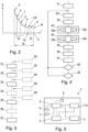
- Steps S1 to S7 do not necessarily have to be carried out in the specified order. Rather, the person skilled in the art can determine an expedient sequence of steps S1 to S7 himself.
- step S1 the sensor 1, 1a is provided as part of a measuring device 2 for measuring the liquid quality and the measuring device 2 is arranged relative to the liquid.
- step S2 the sensor 1, 1a is alternately activated for the duration of a switch-on phase TE and deactivated for the duration of a switch-off phase TA.
- the sensor 1, 1a be activated and deactivated periodically, at least temporarily.
- step S3 during a defined switch-on phase TED, a measured value M is recorded as a comparative measured value V with the sensor 1, 1a G differs.
- step S4 a reference measurement RM for detecting a measured value M representing the liquid quality is carried out as reference measured value R.
- step S4 can also be carried out earlier, in particular if the reference measured value M is determined by a liquid sample taken. The possibility of earlier registration is in 3 indicated by the steps S4 shown in dashed lines.
- step S5 measured values M are continuously recorded as operating measured values B with the sensor 1, 1a during further switch-on phases TEW, which follow the defined switch-on phase TED.
- Steps S2 to S5 are preferably carried out with the same liquid.
- step S6 a calculation rule is defined, which assigns the comparative measured value V to the reference measured value R.
- Step S6 can be carried out as soon as the comparative measured value V and the reference measured value R are known, in particular before step S5.
- step S7 a final measured value F for measuring the quality is determined from each operating measured value B using the calculation rule.
- steps S3 and S5 to S7 are performed during the execution of step S2.
- Step 4 shows a more detailed flowchart according to the method.
- the specified steps S1 to S10 do not necessarily have to be carried out in the specified order.
- Steps S1 to S7 according to 4 correspond to steps S1 through S7 of FIG 3 and are therefore associated with 4 not described again.
- Step S3 may include a step S3a or a step S3b.
- a switch-on phase TE is defined as a defined switch-on phase TED at least when a specified number of previous switch-on phases TE follow a switch-off phase TA that is longer than the duration of the switch-off phase TA or a first-time activation of the sensor 1, 1a.
- a switch-on phase TE is determined at least by the following as a defined switch-on phase TED: Measured values M are recorded with the sensor 1, 1a in a number of successive switch-on phases TE. The measured value M recorded last is compared with the measured value M recorded beforehand.
- the switch-on phase TE for the last measured value M is established as the defined switch-on phase TED.
- the defined switch-on phase TED can also be established in other ways.
- Step S4 may include a step S4a or a step S4b.
- step S4a a liquid sample is taken from the liquid and the reference measured value R of the liquid sample taken is recorded in a device external to the measuring device 2 .
- step S4b the defined switch-on phase TED or a switch-on phase TEV is extended between the defined switch-on phase TED and the further switch-on phases TEW, which are used to record the operating measured values B.
- the reference measured value R is recorded with the sensor 1, 1a.
- the comparative measured value V and/or the operational measured value B is determined by measuring the comparative measured value V and/or the operational measured value B at a specified target time TS within the switch-on phase TE, in particular at the end of the Switch-on phase TEE, are recorded.
- step S6 it can also be provided that the calculation rule is defined as the calculation of a constant factor Q, which is formed from the quotient between the comparative measured value V and the reference measured value R.
- step S7 it can also be provided that the final measured value F is determined from each operational measured value B by dividing the operational measured value B by the calculated constant factor Q.
- Steps S2 to S7 are carried out again in step S8 if a plurality of operational measured values B compared with one another or a plurality of final measured values F compared with one another deviate from one another by more than a previously defined threshold value.
- At least steps S2, S3 and S5 to S7 are carried out again in step S9 if the duration of the switch-on phase TE and/or the duration of the switch-off phase TA has changed by more than a previously defined threshold value.
- step S10 a liquid pump 3 of the measuring device 2, which liquid pump 3 supplies the liquid via the sensor 1, 1a conducts, already activated before the sensor (1, 1a), for example one minute to two minutes before step S2), in particular for a period of time which is sufficient to feed the liquid to the sensor (1, 1a) before the sensor (1 , 1a) activated.
- FIG. 5 shows a simplified block diagram of a measuring device 2 for the power-saving continuous measurement FM of a quality of a liquid, in particular water.
- the measuring device 2 has at least one sensor 1, 1a, a storage device 4 for electrical energy and a controller 5.
- the controller 5 is designed to carry out or to control the method.
- a liquid pump 3 can also be provided.
- the controller 5 is connected to the sensor 1, 1a, the store 4 for electrical energy and the liquid pump 3.
- the store 4 for electrical energy is connected to the sensor 1, 1a and the liquid pump 3.
- the measuring device 2 can also have a data memory 8, an input device 6 for entering parameters, for example a reference value R, and an output device 7 at least for the final measured values F.
- the output device 7 can issue a notification if a plurality of operational measured values B compared with one another or a plurality of final measured values F compared with one another deviate from one another by more than a previously defined threshold value.
Abstract
Messvorrichtung (2) und Verfahren zum stromsparenden fortlaufenden Messen (FM) einer Qualität einer Flüssigkeit, insbesondere Wasser, mit einem Sensor (1, 1a) zur Erfassung einer Messgröße (G), wobei zumindest:- die Messvorrichtung (2) relativ zur Flüssigkeit angeordnet wird;- der Sensor (1, 1a) abwechselnd für die Dauer einer Einschaltphase (TE) aktiviert und für die Dauer einer Ausschaltphase (TA) deaktiviert wird;- mit dem Sensor (1, 1a) während einer definierten Einschaltphase (TED) ein Messwert (M) als Vergleichsmesswert (V) erfasst wird;- eine Referenzmessung (RM) zur Erfassung eines die Flüssigkeitsqualität repräsentierenden Messwerts (M), als Referenzmesswert (R) ausgeführt wird;- mit dem Sensor (1, 1a) während weiterer Einschaltphasen (TEW), welche auf die definierte Einschaltphase (TED) folgen, laufend Messwerte (M) als Betriebsmesswerte (B) erfasst werden;- eine Berechnungsvorschrift festgelegt wird, welche den Vergleichsmesswert (V) dem Referenzmesswert (R) zuordnet; und- mittels der Berechnungsvorschrift aus jedem Betriebsmesswert (B) ein finaler Messwert (F) zur Messung der Qualität ermittelt wird.Measuring device (2) and method for the energy-saving continuous measurement (FM) of a quality of a liquid, in particular water, with a sensor (1, 1a) for detecting a measured variable (G), wherein at least: - the measuring device (2) is arranged relative to the liquid - the sensor (1, 1a) is alternately activated for the duration of a switch-on phase (TE) and deactivated for the duration of a switch-off phase (TA);- a measured value with the sensor (1, 1a) during a defined switch-on phase (TED). (M) is recorded as a comparative measured value (V);- a reference measurement (RM) for recording a measured value (M) representing the liquid quality is carried out as a reference measured value (R);- with the sensor (1, 1a) during further switch-on phases (TEW ) which follow the defined switch-on phase (TED), measured values (M) are continuously recorded as operational measured values (B);- a calculation rule is defined which assigns the comparative measured value (V) to the reference measured value (R); and- a final measured value (F) for measuring the quality is determined from each operational measured value (B) by means of the calculation rule.
Description
Die Erfindung betrifft ein Verfahren zum stromsparenden fortlaufenden Messen einer Qualität einer Flüssigkeit, insbesondere Wasser, mit einem Sensor zur Erfassung einer Messgröße.The invention relates to a method for the energy-saving continuous measurement of a quality of a liquid, in particular water, with a sensor for detecting a measured variable.
Zudem betrifft die Erfindung eine Messvorrichtung zum stromsparenden fortlaufenden Messen einer Qualität einer Flüssigkeit, insbesondere von Wasser, mit einem Sensor.In addition, the invention relates to a measuring device for the energy-saving continuous measurement of a quality of a liquid, in particular of water, with a sensor.
Bekannter Weise wird die Qualität von Flüssigkeit, beispielsweise Wasser, mit Sensoren erfasst, wobei die Sensoren mit elektrischer Energie versorgt werden. Steht hierfür keine externe Stromversorgung dauerhaft zur Verfügung, wird die Energie für die Sensoren mittels elektrischer Energiespeicher, bspw. Batterien, insbesondere wiederaufladbarer Batterien, bereitgestellt. Solche elektrische Energiespeicher werden im Zuge von Wartungstätigkeiten erneuert oder wieder aufgeladen, was jedoch mit einem entsprechenden Wartungsaufwand verbunden ist. Daher ist es wünschenswert, einen geladenen Zustand der Energiespeicher möglichst lange aufrecht zu erhalten, d.h. die Sensoren möglichst stromsparend zu betreiben. Dies wird oftmals durch ein verlängertes Messintervall, d.h. durch größere Zeitabstände zwischen aufeinanderfolgenden Messungen mit dem Sensor erzielt. Zwischen den Messungen wird der Sensor deaktiviert und eine Steuerung für den Sensor wird in einen Ruhe- bzw. Schlafzustand versetzt. Nach Ablauf einer definierten Zeit verlässt die Steuerung den Ruhezustand und aktiviert den Sensor für kurze Zeit, um die Messung auszuführen.As is known, the quality of liquid, for example water, is detected using sensors, the sensors being supplied with electrical energy. If no external power supply is permanently available for this purpose, the energy for the sensors is provided by means of electrical energy stores, for example batteries, in particular rechargeable batteries. Such electrical energy stores are renewed or recharged in the course of maintenance work, but this is associated with a corresponding maintenance effort. It is therefore desirable to keep the energy storage devices in a charged state for as long as possible, i.e. to operate the sensors with as little energy consumption as possible. This is often achieved by extending the measurement interval, i.e. by increasing the time between consecutive measurements with the sensor. The sensor is deactivated between the measurements and a controller for the sensor is put into a rest or sleep state. After a defined time has elapsed, the controller leaves the idle state and activates the sensor for a short time in order to carry out the measurement.
Während ein solcher stromsparender Betrieb für manche Sensoren durchaus zweckmäßig ist, erfordern andere Sensoren zur Messung einer Qualität von Flüssigkeit, insbesondere Wasser, eine im Wesentlichen durchgehende Stromversorgung, zumindest jedoch eine vergleichsweise wesentlich längere Stromversorgung, bspw. von mehreren Stunden, um korrekte Messergebnisse zu liefern. Würden diese anderen Sensoren für mehrere Stunden mit Strom versorgt, um ein einziges Messergebnis zu erhalten, und dann deaktiviert, um Energie zu sparen, erhält man mit diesen anderen Sensoren nur wenige Messergebnisse pro Tag. Eine derart geringe Messrate ist jedoch zur Messung einer Qualität von Flüssigkeit, insbesondere Wasser, oftmals unzureichend.While such power-saving operation is quite appropriate for some sensors, other sensors for measuring the quality of liquid, in particular water, require an essentially continuous power supply, but at least a comparatively much longer power supply, e.g. several hours, in order to deliver correct measurement results . If these other sensors were powered on for several hours to get a single reading and then turned off to save power, those other sensors would only get a few readings per day. However, such a low measuring rate is often insufficient for measuring a quality of liquid, in particular water.
Wie in
Die
Die
Die Aufgabe der Erfindung besteht in der Schaffung eines Verfahrens und einer Messvorrichtung der eingangs genannten Art, welche eine stromsparende fortlaufende Messung einer Qualität einer Flüssigkeit, insbesondere Wasser, mit einem Sensor ermöglichen. Insbesondere soll der Sensor im Vergleich zu einem üblichen Betrieb mit geringerem Stromverbrauch betrieben werden, wobei dennoch Messergebnisse mit im Wesentlichen gleicher Genauigkeit wie im Fall des üblichen Betriebs mit höherem Stromverbrauch erhalten werden.The object of the invention is to create a method and a measuring device of the type mentioned at the outset, which enable a power-saving continuous measurement of a quality of a liquid, in particular water, with a sensor. In particular, the sensor should be operated with lower power consumption compared to normal operation, while measurement results are nevertheless obtained with essentially the same accuracy as in the case of normal operation with higher power consumption.
Hierfür sieht die Erfindung ein Verfahren wie in Anspruch 1 und eine Messvorrichtung wie in Anspruch 14 definiert vor. Vorteilhafte Ausführungsformen und Weiterbildungen sind in den abhängigen Ansprüchen angegeben.For this purpose the invention provides a method as defined in
Die Aufgabe wird erfindungsgemäß durch ein Verfahren zum stromsparenden fortlaufenden Messen einer Qualität einer Flüssigkeit, insbesondere Wasser, mit einem Sensor zur Erfassung einer Messgröße gelöst, wobei:
- S1) der Sensor als Teil einer Messvorrichtung zur Messung der Flüssigkeitsqualität bereitgestellt und die Messvorrichtung relativ zur Flüssigkeit angeordnet wird;
- S2) der Sensor abwechselnd für die Dauer einer Einschaltphase aktiviert und für die Dauer einer Ausschaltphase deaktiviert wird;
- S3) mit dem Sensor während einer definierten Einschaltphase ein Messwert als Vergleichsmesswert erfasst wird, für welche definierte Einschaltphase sich der Vergleichsmesswert um höchstens eine vorgegebene Differenz von einem während einer vorherigen Einschaltphase erfassbaren Wert der Messgröße unterscheidet;
- S4) eine Referenzmessung zur Erfassung eines die Flüssigkeitsqualität repräsentierenden Messwerts, als Referenzmesswert ausgeführt wird;
- S5) mit dem Sensor während weiterer Einschaltphasen, welche auf die definierte Einschaltphase folgen, laufend Messwerte als Betriebsmesswerte erfasst werden;
- S6) eine Berechnungsvorschrift festgelegt wird, welche den Vergleichsmesswert dem Referenzmesswert zuordnet; und S7) mittels der Berechnungsvorschrift aus jedem Betriebsmesswert ein finaler Messwert zur Messung der Qualität ermittelt wird.
- S1) the sensor is provided as part of a measuring device for measuring the quality of the liquid and the measuring device is arranged relative to the liquid;
- S2) the sensor is alternately activated for the duration of a switch-on phase and deactivated for the duration of a switch-off phase;
- S3) a measured value is recorded with the sensor as a comparative measured value during a defined switch-on phase, for which defined switched-on phase the comparative measured value differs by at most a predetermined difference from a value of the measured variable that can be recorded during a previous switch-on phase;
- S4) a reference measurement for detecting a measured value representing the liquid quality is carried out as a reference measured value;
- S5) measured values are continuously recorded as operating measured values with the sensor during further switch-on phases which follow the defined switch-on phase;
- S6) a calculation rule is defined which assigns the comparative measured value to the reference measured value; and S7) a final measured value for measuring the quality is determined from each operational measured value by means of the calculation rule.
Der Sensor wird somit in einem Schritt S1 als Teil einer Messvorrichtung zur Messung der Flüssigkeitsqualität bereitgestellt und die Messvorrichtung wird relativ zur Flüssigkeit angeordnet. Dabei wird der Sensor in der Flüssigkeit angeordnet. Der den Sensor nicht enthaltende Teil der Messvorrichtung kann zumindest teilweise in der Flüssigkeit oder in einem Abstand von der Flüssigkeit angeordnet werden. Bspw. ist der den Sensor nicht enthaltende Teil der Messvorrichtung über ein elektrisch leitendes Kabel mit dem Sensor verbunden. Alternativ kann der Sensor in die Messvorrichtung eingesetzt sein.The sensor is thus provided in a step S1 as part of a measuring device for measuring the liquid quality and the measuring device is arranged relative to the liquid. The sensor is placed in the liquid. The part of the measuring device not containing the sensor can be arranged at least partly in the liquid or at a distance from the liquid. For example, the part of the measuring device that does not contain the sensor is connected to the sensor via an electrically conductive cable. Alternatively, the sensor can be inserted into the measuring device.
In einem Schritt S2 wird der Sensor abwechselnd für die Dauer einer Einschaltphase aktiviert und für die Dauer einer Ausschaltphase deaktiviert. Im aktivierten Zustand wird der Sensor mit elektrischem Strom versorgt und im deaktivierten Zustand nicht mit elektrischem Strom versorgt. Hierdurch wird der Sensor stromsparend betrieben und das Verfahren stromsparend durchgeführt. Die Dauer der Einschaltphase und die Dauer der Ausschaltphase können von einem Betreiber der Messvorrichtung eingestellt werden.In a step S2, the sensor is alternately activated for the duration of a switch-on phase and deactivated for the duration of a switch-off phase. The sensor is supplied with electrical current in the activated state and is not supplied with electrical current in the deactivated state. As a result, the sensor is operated in a power-saving manner and the method is carried out in a power-saving manner. The duration of the switch-on phase and the duration of the switch-off phase can be set by an operator of the measuring device.
In einem Schritt S3 wird mit dem Sensor während einer definierten Einschaltphase ein Messwert als Vergleichsmesswert erfasst. In der definierten Einschaltphase unterscheidet sich der Vergleichsmesswert um höchstens eine vorgegebene Differenz von einem während einer vorherigen Einschaltphase erfassbaren Wert der Messgröße. Es sei darauf hingewiesen, dass sich der mit dem Sensor erfassbare Wert der Messgröße, selbst bei konstanter Messgröße, wegen des abwechselnden Aktivierens und Deaktivierens des Sensors während der Einschaltphasen ändert. Wenn daher im weiteren Verlauf der Beschreibung auf eine Erfassung mehrerer Messwerte oder einen Vergleich mehrerer Messwerte Bezug genommen wird, so ist dies selbstverständlich so zu verstehen, dass die Messwerte zu ähnlichen, insbesondere gleichen Zeitabständen vom Beginn der jeweiligen Einschaltphase erfasst bzw. betrachtet werden, um korrekte und vergleichbare Messergebnisse zu erhalten. Somit werden für einen korrekten Vergleich der Vergleichsmesswert und der Wert der Messgröße einer vorherigen Einschaltphase bevorzugt in gleichen Zeitabständen vom Beginn der jeweiligen Einschaltphase erfasst bzw. betrachtet. Hinsichtlich der Einschaltphase kann von einem Betreiber der Messvorrichtung festgelegt werden, welche Einschaltphase die definierte Einschaltphase ist. Der Vergleichsmesswert wird somit am Ende oder nach einer Einschwingphase des abwechselnd aktivierten und deaktivierten Sensors erfasst, wobei dann die Werte der Messgröße in gleichen Abständen vom Beginn der Einschaltphasen im Wesentlichen stabil sind, d.h. sich um nicht mehr als die vorgegebene Differenz voneinander unterscheiden. Diese Einschwingphase liegt vor, wenn der Sensor nach einer im Vergleich zur Dauer der Ausschaltphase verlängerten Ausschaltphase, die bspw. zu Wartungszwecken erforderlich war, oder nach einer erstmaligen Aktivierung des Sensors abwechselnd aktiviert und deaktiviert wird. Während der Einschwingphase werden sich die Werte der Messgröße in mehreren aufeinanderfolgenden Einschaltphasen und in gleichen Abständen vom Beginn der Einschaltphasen betrachtet zunächst unterscheiden, sich jedoch zunehmend an den Vergleichsmesswert annähern. Somit wird in Schritt S3 ein für die Dauer einer Einschaltphase des eingeschwungenen Sensors repräsentativer Vergleichsmesswert erfasst.In a step S3, a measured value is recorded as a comparative measured value with the sensor during a defined switch-on phase. In the defined switch-on phase, the comparative measured value differs by at most a predetermined difference from a value of the measured variable that can be detected during a previous switch-on phase. It should be noted that the value of the measurand that can be detected by the sensor changes, even if the measurand is constant, due to the alternating activation and deactivation of the sensor during the switch-on phases. If, in the further course of the description, reference is made to the acquisition of several measured values or a comparison of several measured values, this is of course to be understood in such a way that the measured values are acquired or considered at similar, in particular equal, time intervals from the start of the respective switch-on phase in order to obtain correct and comparable measurement results. Thus, for a correct comparison, the comparative measured value and the value of the measured variable of a previous switch-on phase are preferably recorded or considered at equal time intervals from the beginning of the respective switch-on phase. With regard to the switch-on phase, an operator of the measuring device can specify which switch-on phase is the defined switch-on phase. The comparative measured value is thus recorded at the end or after a transient phase of the alternately activated and deactivated sensor, the values of the measured variable then being essentially stable at equal intervals from the start of the switch-on phases, ie differing from one another by no more than the specified difference. This transient phase occurs when the sensor is alternately activated and deactivated after a switch-off phase that is longer than the duration of the switch-off phase, which was required for maintenance purposes, for example, or after the sensor was activated for the first time. During the transient phase, the values of the measured variable in several consecutive switch-on phases and viewed at equal intervals from the start of the switch-on phases will initially differ, but will increasingly approach the comparative measured value. Thus, in step S3, a comparative measured value that is representative of the duration of a switch-on phase of the settled sensor is recorded.
In einem Schritt S4 wird eine Referenzmessung zur Erfassung eines die Flüssigkeitsqualität repräsentierenden Messwerts als Referenzmesswert ausgeführt. Die Referenzmessung erfasst den Messwert mit einer Genauigkeit, die bspw. oder annähernd auch mit dem Sensor erzielbar wäre, wenn dieser dauerhaft aktiviert wäre.In a step S4, a reference measurement is carried out to record a measured value representing the liquid quality as a reference measured value. The reference measurement captures the measured value with an accuracy that could be achieved, for example or approximately, with the sensor if it were permanently activated.
In einem Schritt S5 werden mit dem Sensor während weiterer Einschaltphasen, welche auf die definierte Einschaltphase folgen, laufend Messwerte als Betriebsmesswerte erfasst. Die Erfassung der Betriebsmesswerte entspricht dabei dem fortlaufenden Messen einer Qualität der Flüssigkeit, insbesondere Wasser, und wird spätestens durch eine Wartungsaktivität eines Betreibers der Messvorrichtung, bspw. für einen Batterietausch, unterbrochen. Bevorzugt werden die Betriebsmesswerte für eine korrekte Messung in gleichen Abständen vom Beginn der Einschaltphasen erfasst.In a step S5, measured values are continuously recorded as operating measured values with the sensor during further switch-on phases which follow the defined switch-on phase. In this case, the acquisition of the operating measured values corresponds to the continuous measurement of a quality of the liquid, in particular water, and is interrupted at the latest by a maintenance activity by an operator of the measuring device, for example for a battery replacement. For a correct measurement, the operating measured values are preferably recorded at equal intervals from the start of the switch-on phases.
In einem Schritt S6 wird eine Berechnungsvorschrift festgelegt, welche den Vergleichsmesswert dem Referenzmesswert zuordnet. Die Berechnungsvorschrift kann bspw. in einer Steuerung der Messvorrichtung ermittelt und in einem Speicher der Messvorrichtung abgelegt werden.In a step S6, a calculation rule is defined, which assigns the comparative measured value to the reference measured value. The calculation rule can be determined, for example, in a controller of the measuring device and stored in a memory of the measuring device.
In einem Schritt S7 wird mittels der Berechnungsvorschrift aus jedem Betriebsmesswert ein finaler Messwert zur Messung der Qualität der Flüssigkeit ermittelt. Der finale Messwert repräsentiert somit die Qualität der Flüssigkeit, insbesondere Wasser.In a step S7, a final measured value for measuring the quality of the liquid is determined from each operational measured value using the calculation rule. The final measured value thus represents the quality of the liquid, especially water.
Das Verfahren sieht somit vor, den Sensor nicht wie üblich dauerhaft mit Strom zu versorgen, sondern abwechselnd zu aktivieren und deaktivieren, um Energie zu sparen und einen Energiespeicher zur Stromversorgung möglichst selten tauschen bzw. wieder aufladen zu müssen. Nach einer Einschwingphase des Sensors wird in einer vergleichsweise kurzen Einschaltphase ein Vergleichsmesswert mit geringerer Genauigkeit erfasst und einem Referenzmesswert mit höherer Genauigkeit zugeordnet. Im fortlaufenden Messbetrieb werden während weiterer vergleichsweise kurzer Einschaltphasen Betriebsmesswerte mit geringerer Genauigkeit erfasst. Schließlich werden mit Hilfe des Zusammenhangs zwischen dem Vergleichsmesswert und dem Referenzmesswert die Ungenauigkeiten der Betriebsmesswerte korrigiert, wodurch finale Messwerte mit höherer Genauigkeit erhalten werden.The method thus provides for the sensor not to be permanently supplied with electricity as is usual, but to be activated and deactivated alternately in order to save energy and to have to exchange or recharge an energy store for the power supply as rarely as possible. After a transient phase of the sensor, in a comparatively short switch-on phase, a comparative measured value is recorded with less accuracy and assigned to a reference measured value with higher accuracy. In continuous measurement operation, operating measurement values are recorded with less accuracy during further comparatively short switch-on phases. Finally, the inaccuracies in the operational measured values are corrected with the aid of the relationship between the comparison measured value and the reference measured value, as a result of which final measured values with greater accuracy are obtained.
Gemäß einer bevorzugten Ausführungsform des Verfahrens ist vorgesehen, dass für die Ausführung der Referenzmessung S4a) eine Flüssigkeitsprobe von der Flüssigkeit entnommen wird und der Referenzmesswert der entnommenen Flüssigkeitsprobe in einer zur Messvorrichtung externen Vorrichtung erfasst wird; oder
S4b) die definierte Einschaltphase oder eine Einschaltphase zwischen der definierten Einschaltphase und den weiteren Einschaltphasen zur Erfassung der Betriebsmesswerte verlängert wird, und während der verlängerten Einschaltphase der Referenzmesswert mit dem Sensor erfasst wird.According to a preferred embodiment of the method it is provided that for the execution of the reference measurement S4a) a liquid sample is taken from the liquid and the reference measured value of the taken liquid sample is recorded in a device external to the measuring device; or
S4b) the defined switch-on phase or a switch-on phase between the defined switch-on phase and the further switch-on phases is extended to record the operating measured values, and the reference measured value is recorded with the sensor during the extended switch-on phase.
Die Referenzmessung wird somit im Vergleich zur Messung während einer Einschaltphase mit höherer Genauigkeit durchgeführt. Dabei kann eine Referenzmessung an einer Flüssigkeitsprobe in einer externen Vorrichtung mit bekannten Verfahrensschritten und mit bekannten Messvorrichtungen ohne Verwendung des Sensors erfolgen. In diesem Fall erfolgt die Referenzmessung bevorzugt vor der Ermittlung des ersten Betriebsmesswerts, bspw. vor oder während der definierten Einschaltphase des Sensors. Alternativ kann die Referenzmessung während einer verlängerten Einschaltphase mit dem Sensor selbst erfolgen. Wenn hierfür die definierte Einschaltphase verlängert wird, erfolgt die Referenzmessung in der definierten Einschaltphase nach der Erfassung des Vergleichsmesswerts.The reference measurement is thus compared to the measurement during carried out with higher accuracy during a switch-on phase. A reference measurement can be carried out on a liquid sample in an external device with known method steps and with known measuring devices without using the sensor. In this case, the reference measurement preferably takes place before the determination of the first operational measured value, for example before or during the defined switch-on phase of the sensor. Alternatively, the reference measurement can be performed with the sensor itself during an extended switch-on phase. If the defined switch-on phase is extended for this purpose, the reference measurement takes place in the defined switch-on phase after the comparison measured value has been recorded.
Wenn der Sensor zumindest zeitweise periodisch aktiviert und deaktiviert wird, kann die Genauigkeit des Vergleichsmesswerts und/oder der Betriebsmesswerte verbessert werden. Dies kann damit begründet werden, dass die Messwerte des Sensors nicht nur vom Wert der Messgröße selbst, sondern auch von der Dauer der vorangegangenen Einschaltphasen und Ausschaltphasen abhängen können. Ständig variierende Dauern der Einschaltphasen und Ausschaltphasen können daher auch bei einem gleichbleibenden Wert der Messgröße zu variierenden Messwerten führen. Besonders bevorzugt wird der Sensor während des laufenden Messbetriebs, nach der definierten Einschaltphase, zumindest zeitweise periodisch aktiviert und deaktiviert.If the sensor is activated and deactivated periodically, at least temporarily, the accuracy of the comparative measured value and/or the operational measured values can be improved. This can be justified by the fact that the measured values of the sensor can depend not only on the value of the measured variable itself, but also on the duration of the previous switch-on and switch-off phases. Constantly varying durations of the switch-on phases and switch-off phases can therefore lead to varying measured values even if the value of the measured variable remains the same. Particularly preferably, the sensor is periodically activated and deactivated at least temporarily during the ongoing measurement operation after the defined switch-on phase.
Betreffend die definierte Einschaltphase kann vorgesehen sein, dass
S3a) eine Einschaltphase zumindest dann als definierte Einschaltphase festgelegt wird, wenn eine festgelegte Anzahl von vorangehenden Einschaltphasen auf eine im Vergleich zur Dauer der Ausschaltphase verlängerte Ausschaltphase oder eine erstmalige Aktivierung des Sensors folgen.Regarding the defined switch-on phase, it can be provided that
S3a) a switch-on phase is defined as a defined switch-on phase at least when a specified number of preceding switch-on phases follow a switch-off phase that is longer than the duration of the switch-off phase or a first-time activation of the sensor.
Die Anzahl von vorangehenden Einschaltphasen kann einstellbar sein. Beispielsweise kann ein Betreiber der Messvorrichtung diese Anzahl auf Grundlage von Erfahrungswerten festlegen. Die Anzahl von vorangehenden Einschaltphasen und somit auch vorangehenden Ausschaltphasen kann derart festgelegt werden, dass sich der Sensor danach zuverlässig im eingeschwungenen Zustand befindet. Gezählt wird die festgelegte Anzahl von vorangehenden Einschaltphasen von einem Zeitpunkt des erstmaligen Einschaltens des Sensors oder im Anschluss an eine längere Betriebsunterbrechung des Sensors, d.h. an eine Ausschaltphase, die im Vergleich zur Dauer vorangegangener Ausschaltphasen oder zu einer durchschnittlichen Dauer vorangegangener Ausschaltphasen länger ist. Beispielsweise kann eine durchschnittliche Ausschaltphase 20 Minuten betragen, während eine Betriebsunterbrechung 1 Stunde betragen kann.The number of previous switch-on phases can be adjustable. For example, an operator of the measuring device can specify this number on the basis of empirical values. The number of preceding switch-on phases and thus also preceding switch-off phases can be specified in such a way that the sensor is then reliably in the steady state. The specified number of previous switch-on phases is counted from a point in time when the sensor is switched on for the first time or following a longer interruption in operation of the sensor, i.e. a switch-off phase that is longer compared to the duration of previous switch-off phases or to an average duration of previous switch-off phases. For example, an average off-time may be 20 minutes, while an outage may be 1 hour.
Betreffend die definierte Einschaltphase kann weiters vorgesehen sein, dass
S3b) eine Einschaltphase zumindest durch folgendes als definierte Einschaltphase festgelegt wird:
- Erfassen von Messwerten mit dem Sensor in mehreren aufeinander folgenden Einschaltphasen;
- Vergleichen des zuletzt erfassten Messwerts mit dem davor erfassten Messwert; und
- im Falle einer einen vorab definierten Schwellenwert unterschreitenden Abweichung der beiden verglichenen Messwerte voneinander, Festlegen der Einschaltphase für den letzten Messwert als die definierte Einschaltphase.
S3b) a switch-on phase is defined as a defined switch-on phase at least by the following:
- Acquiring measured values with the sensor in several successive switch-on phases;
- comparing the most recently acquired reading to the previously acquired reading; and
- in the case of a deviation of the two compared measured values from one another that falls below a previously defined threshold value, the switch-on phase for the last measured value is determined as the defined switch-on phase.
Hierdurch kann jene Einschaltphase als definierte Einschaltphase festgelegt werden, für welche sich der Messwert um weniger als den definierten Schwellenwert vom vorherigen Messwert unterscheidet. Der Sensor befindet sich somit im eingeschwungenen Zustand. Für einen korrekten Vergleich der Messwerte werden die Messwerte bevorzugt in gleichen Zeitabständen vom Beginn der jeweiligen Einschaltphase erfasst.As a result, that switch-on phase can be defined as a defined switch-on phase for which the measured value differs from the previous measured value by less than the defined threshold value. The sensor is thus in the steady state. For a correct comparison of the measured values, the measured values are preferably recorded at equal time intervals from the beginning of the respective switch-on phase.
Weiters ist es günstig, wenn der Vergleichsmesswert und/oder der Betriebsmesswert durch Messen des Vergleichsmesswerts und/oder des Betriebsmesswerts zu einem festgelegten Soll-Zeitpunkt innerhalb der Einschaltphase, insbesondere am Ende der Einschaltphase, erfasst werden. Auf diese Weise können besonders zuverlässige Messergebnisse erzielt werden, da sich, wie zuvor bereits erwähnt, selbst bei konstanter Messgröße der mit dem Sensor erfassbare Wert der Messgröße wegen des abwechselnden Aktivierens und Deaktivierens des Sensors während der Einschaltphasen ändert. Der Soll-Zeitpunkt kann bspw. von einem Betreiber der Messvorrichtung festgelegt werden und einstellbar sein. Der Soll-Zeitpunkt kann, muss aber nicht am Ende der Einschaltphase liegen.Furthermore, it is favorable if the comparative measured value and/or the operational measured value are recorded by measuring the comparative measured value and/or the operational measured value at a specified target time within the switch-on phase, in particular at the end of the switch-on phase. Particularly reliable measurement results can be achieved in this way because, as already mentioned, the value of the measured variable that can be detected with the sensor changes even if the measured variable is constant because of the alternating activation and deactivation of the sensor during the switch-on phases changes. The target point in time can, for example, be defined and adjusted by an operator of the measuring device. The target time can, but does not have to be at the end of the switch-on phase.
Weiters kann vorgesehen sein, dass der Vergleichsmesswert und/oder der Betriebsmesswert durch folgendes erfasst werden:
- Messen mit dem Sensor zu mehreren Zeitpunkten innerhalb der dem Vergleichsmesswert und/oder Betriebsmesswert zugeordneten Einschaltphase, um mehrere Abtastwerte zu erhalten;
- Berechnen eines an die Abtastwerte angenäherten Messwertverlaufs innerhalb der Einschaltphase;
- Messen zu welchem Ist-Zeitpunkt der für die Messung zu einem definierten Soll-Zeitpunkt vorgesehene Vergleichsmesswert und/oder Betriebsmesswert tatsächlich gemessen wurde; und
- im Falle einer Abweichung des Ist-Zeitpunkts vom Soll-Zeitpunkt, Berechnen des Vergleichsmesswerts und/oder Betriebsmesswerts zum Soll-Zeitpunkt mittels des angenäherten Messwertverlaufs.
- Measuring with the sensor at a number of points in time within the switch-on phase associated with the comparative measured value and/or operational measured value in order to obtain a number of sampled values;
- Calculation of a measured value curve approximated to the sampled values within the switch-on phase;
- measuring at which actual time the comparative measured value and/or operational measured value provided for the measurement at a defined target time was actually measured; and
- in the case of a deviation of the actual time from the target time, calculation of the comparative measured value and/or operational measured value at the target point in time using the approximated measured value curve.
Auf diese Weise können Fehler bei der Erfassung des Vergleichsmesswerts und/oder Betriebsmesswerts korrigiert werden, welche Fehler dadurch entstehen können, dass der beabsichtigte Messzeitpunkt, d.h. der Soll-Zeitpunkt, nicht eingehalten werden kann. Bspw. kann der Soll-Zeitpunkt wegen systembedingter Ungenauigkeiten, wie einer vorübergehenden Überlastung eines Prozessors der Messvorrichtung, nicht eingehalten werden. Aus der Kenntnis des Messwertverlaufs innerhalb der Einschaltphase kann der Messwert zum vorgesehenen Soll-Zeitpunkt aus dem zum Ist-Zeitpunkt erfassten Messwert, vorzugsweise durch die Messvorrichtung selbst, berechnet werden, insbesondere durch Interpolation oder Extrapolation. Dabei kann der Soll-Zeitpunkt zeitlich vor oder nach dem Ist-Zeitpunkt liegen.In this way, errors in the detection of the comparative measured value and/or operational measured value can be corrected, which errors can arise because the intended measurement time, i.e. the target time, cannot be observed. For example, the target time cannot be adhered to due to system-related inaccuracies, such as a temporary overload of a processor of the measuring device. From the knowledge of the course of the measured value within the switch-on phase, the measured value at the intended target time can be calculated from the measured value recorded at the actual time, preferably by the measuring device itself, in particular by interpolation or extrapolation. The target time can be before or after the actual time.
Eine besonders einfache Ausführungsform kann vorsehen, dass
- die Berechnungsvorschrift als Berechnen eines konstanten Faktors, welcher aus dem Quotienten zwischen dem Vergleichsmesswert und dem Referenzmesswert gebildet wird, festgelegt wird und
- der finale Messwert aus jedem Betriebsmesswert durch Dividieren des Betriebsmesswerts durch den berechneten konstanten Faktor ermittelt wird.
- the calculation specification is defined as calculating a constant factor, which is formed from the quotient between the comparative measured value and the reference measured value, and
- the final reading from each operational reading by dividing the operational reading by the calculated constant factor is determined.
Es gilt demnach ![]()
![]()
![]()
![]()
Die durch diese Gleichungen berechneten finalen Messwerte werden den tatsächlichen Wert der Messgröße sehr gut annähern, solange die Betriebsmesswerte nur geringfügig vom Vergleichsmesswert abweichen. Mit zunehmender Abweichung, bspw. in Folge einer Veränderung der Flüssigkeitsqualität, wird diese einfache Berechnungsvorschrift wegen des nicht linearen Verlaufs der Messgröße in der Einschaltphase ungenauer.The final measured values calculated by these equations will approximate the actual value of the measurand very closely as long as the operational measured values deviate only slightly from the comparative measured value. As the deviation increases, for example as a result of a change in the liquid quality, this simple calculation rule becomes less precise due to the non-linear course of the measured variable in the switch-on phase.
Um möglichst korrekte finale Messwerte zu erzielen ist es günstig, wenn
S8) die Schritte S2) bis S7) erneut durchgeführt werden, wenn mehrere miteinander verglichene Betriebsmesswerte oder mehrere miteinander verglichene finale Messwerte um mehr als einen vorab definierten Schwellenwert voneinander abweichen.In order to achieve the most correct possible final measured values, it is favorable if
S8) steps S2) to S7) are performed again if a plurality of operational measured values compared with one another or a plurality of final measured values compared with one another deviate from one another by more than a previously defined threshold value.
Eine solche Abweichung mehrerer miteinander verglichener Betriebsmesswerte oder finaler Messwerte ist ein Hinweis auf eine sich verändernde Qualität der Flüssigkeit. Demnach sind auch ein geänderter Vergleichsmesswert und ein geänderter Referenzmesswert erwartbar, weshalb die Schritte S2) bis S7) des Verfahrens bevorzugt erneut durchgeführt werden. Der vorab definierte Schwellenwert kann bspw. von einem Betreiber der Messvorrichtung eingestellt werden. Bevorzugt werden zuletzt gemessene Betriebsmesswerte oder zuletzt berechnete finale Messwerte mit länger zurückliegenden Betriebsmesswerten oder finalen Messwerten verglichen.Such a deviation of several operational measured values compared with one another or final measured values is an indication of a changing quality of the liquid. Accordingly, a changed comparative measured value and a changed reference measured value can also be expected, which is why steps S2) to S7) of the method are preferably carried out again. The previously defined threshold value can be set, for example, by an operator of the measuring device. Last measured operating values or last calculated final measured values are preferably compared with operating measured values or final measured values that are longer in the past.
Des weiteren wird bevorzugt, dass
S9) zumindest die Schritte S2), S3) und S5) bis S7) erneut durchgeführt werden, wenn die Dauer der Einschaltphase und/oder die Dauer der Ausschaltphase um mehr als einen vorab definierten Schwellenwert geändert wurde. Die Änderung der Dauer der Einschaltphase und/oder der Dauer der Ausschaltphase kann von einem Betreiber der Messvorrichtung durchgeführt werden, bspw. um finale Messwerte in kürzeren Zeitabständen zu erhalten oder die Stromeinsparung durch den Sensor noch weiter zu erhöhen. Da die mit dem Sensor erfassbaren Messwerte auch von der Dauer der Einschaltphase und/oder der Dauer der Ausschaltphase abhängen, ist auch ein geänderter Vergleichsmesswert erwartbar, weshalb zumindest die Schritte S2), S3) und S5) bis S7) des Verfahrens bevorzugt erneut durchgeführt werden. Wenn der Vorgang der Referenzmessung von den geänderten Einschaltphasen/Ausschaltphasen unabhängig ist und somit kein neuer Referenzmesswert erwartbar ist, kann der Schritt S4) der erneuten Referenzmessung auch entfallen.Furthermore, it is preferred that
S9) at least steps S2), S3) and S5) to S7) are carried out again if the duration of the switch-on phase and/or the duration of the switch-off phase has been changed by more than a previously defined threshold value. Changing the duration of the switch-on phase and/or the duration of the switch-off phase can be carried out by an operator of the measuring device, for example in order to obtain final measured values at shorter time intervals or to further increase the power savings by the sensor. Since the measured values that can be recorded with the sensor also depend on the duration of the switch-on phase and/or the duration of the switch-off phase, a changed comparative measured value can also be expected, which is why at least steps S2), S3) and S5) to S7) of the method are preferably carried out again . If the process of the reference measurement is independent of the changed switch-on phases/switch-off phases and therefore no new reference measured value can be expected, step S4) of renewed reference measurement can also be omitted.
Um korrekte finale Messwerte zu erhalten ist es zweckmäßig, wenn die Schritte S2) bis S5) mit der gleichen Flüssigkeit durchgeführt werden.In order to obtain correct final measured values, it is expedient if steps S2) to S5) are carried out with the same liquid.
Zur Erzielung korrekter finaler Messwerte mit Messvorrichtungen, in welchen eine Flüssigkeitszufuhr zum Sensor durch eine Flüssigkeitspumpe ausgeführt ist, ist es weiterhin günstig, wenn S10) eine Flüssigkeitspumpe der Messvorrichtung, welche Flüssigkeitspumpe die Flüssigkeit über den Sensor leitet, bereits vor dem Sensor aktiviert wird, beispielsweise eine Minute bis zwei Minuten vor dem Schritt S2) aktiviert wird, insbesondere für einen Zeitraum welcher ausreichend ist, die Flüssigkeit dem Sensor zuzuführen, vor dem Sensor aktiviert wird. Dies ist zweckmäßig, damit die Flüssigkeit am Sensor vorab ausgetauscht wird und unmittelbar zu dessen Einschaltzeitpunkt bereits repräsentativ jener Flüssigkeit entspricht, die an der Entnahmestelle, zum Beispiel in einem Versorgungsrohr, vorliegt.In order to achieve correct final measured values with measuring devices in which liquid is supplied to the sensor by a liquid pump, it is also favorable if S10) a liquid pump of the measuring device, which liquid pump directs the liquid via the sensor, is already activated before the sensor, for example one minute to two minutes before step S2), in particular for a period of time sufficient to supply the liquid to the sensor before the sensor is activated. This is expedient so that the liquid on the sensor is exchanged in advance and immediately at the time when it is switched on is representative of the liquid that is present at the sampling point, for example in a supply pipe.
Besonders bevorzugt wird, dass als Sensor ein Sensor zur Messung der Konzentration eines Desinfektionsmittels, insbesondere zur Messung einer Chlorkonzentration, oder zur Messung eines pH-Werts, verwendet wird. Diese Sensoren erfordern für gewöhnlich lange Aktivierungszeiten, bevorzugt einen durchgehenden Betrieb, um korrekte Messergebnisse zu liefern. Zudem sind diese Sensoren zumindest in Bezug auf wechselnder Qualität der Flüssigkeit, variierenden Dauern der Einschaltphase und Ausschaltphase, der Anzahl vorangegangener Einschaltphasen und Ausschaltphasen und der Verweildauer in der Flüssigkeit besonders empfindlich. Mit dem erfindungsgemäßen Verfahren können auch mit solchen Sensoren auf stromsparende Weise finale Messwerte mit einer Genauigkeit erzielt werden, welche Genauigkeit nur durch kürzere Einschaltphasen allein nicht erzielbar wäre.It is particularly preferred that a sensor for measuring the concentration of a disinfectant, in particular for measuring a chlorine concentration, or for measuring a pH value is used as the sensor. These sensors usually require long activation times, preferably continuous operation, to provide correct measurement results. In addition, these sensors are at least in relation to the changing quality of the liquid, varying durations of the switch-on and switch-off phase, the number previous switch-on and switch-off phases and the dwell time in the liquid are particularly sensitive. With the method according to the invention, final measured values can also be achieved with such sensors in a power-saving manner with an accuracy that would not be achievable with shorter switch-on phases alone.
Die eingangs gestellte Aufgabe wird erfindungsgemäß zudem durch eine Messvorrichtung zum stromsparenden fortlaufenden Messen einer Qualität einer Flüssigkeit, insbesondere von Wasser, aufweisend zumindest einen Sensor, einen Speicher für elektrische Energie und eine Steuerung gelöst, welche dadurch gekennzeichnet ist, dass die Steuerung zur Durchführung eines Verfahrens gemäß der vorangehenden Beschreibung ausgebildet ist. Die Messvorrichtung weist demnach zumindest einen Sensor auf, mit welchem Werte der die Flüssigkeitsqualität repräsentierenden Messgröße, bspw. eine Konzentration eines Desinfektionsmittels, eine Chlorkonzentration oder ein pH-Wert erfasst werden können. Um die Messvorrichtung unabhängig von einem Stromanschluss betreiben zu können, weist diese den Speicher für elektrische Energie auf. Die Steuerung der Messvorrichtung ist ausgebildet, die Durchführung des zuvor beschriebenen Verfahrens zu steuern. Hierfür weist die Messvorrichtung bevorzugt einen Mikroprozessor und einen Datenspeicher auf. Hinsichtlich der Merkmale der Messvorrichtung wird zudem auf die vorangehende Beschreibung des Verfahrens verwiesen, soweit diese für das Verständnis der Messvorrichtung hilfreich ist und soweit aus dieser Beschreibung des Verfahrens Merkmale der Messvorrichtung ableitbar sind. Ebenso wird hinsichtlich der Merkmale des Verfahrens auch auf die Beschreibung der Messvorrichtung verwiesen.The task stated at the outset is also achieved according to the invention by a measuring device for the energy-saving continuous measurement of the quality of a liquid, in particular water, having at least one sensor, a storage device for electrical energy and a controller, which is characterized in that the controller is used to carry out a method is designed according to the previous description. The measuring device therefore has at least one sensor with which values of the measured variable representing the liquid quality, for example a concentration of a disinfectant, a chlorine concentration or a pH value, can be detected. In order to be able to operate the measuring device independently of a power connection, it has the storage device for electrical energy. The controller of the measuring device is designed to control the implementation of the method described above. For this purpose, the measuring device preferably has a microprocessor and a data memory. With regard to the features of the measuring device, reference is also made to the previous description of the method, insofar as this is helpful for understanding the measuring device and insofar as features of the measuring device can be derived from this description of the method. With regard to the features of the method, reference is also made to the description of the measuring device.
Besonders bevorzugt ist der Sensor zur Messung der Konzentration eines Desinfektionsmittels, insbesondere zur Messung einer Chlorkonzentration, oder zur Messung eines pH-Werts ausgebildet.The sensor is particularly preferably designed to measure the concentration of a disinfectant, in particular to measure a chlorine concentration, or to measure a pH value.
Die Erfindung wird im Folgenden anhand von bevorzugten, nicht einschränkenden Ausführungsbeispielen unter Bezugnahme auf die Zeichnung noch weiter erläutert. Es zeigen:
-
Fig. 1 eine schematische Darstellung eines Teils des zeitlichen Ablaufs des Verfahrens gemäß der Erfindung; -
Fig. 2 eine schematische Darstellung des zeitlichen Ablaufs einer Einschaltphase in größerem Maßstab; -
Fig. 3 ein Ablaufdiagramm zum Verfahren gemäß der Erfindung; -
Fig. 4 ein detaillierteres Ablaufdiagramm zum Verfahren gemäß der Erfindung; und -
Fig. 5 ein vereinfachtes Blockschaltbild der Messvorrichtung gemäß der Erfindung.
-
1 a schematic representation of part of the temporal Flow of the method according to the invention; -
2 a schematic representation of the timing of a switch-on phase on a larger scale; -
3 a flowchart for the method according to the invention; -
4 a more detailed flow chart of the method according to the invention; and -
figure 5 a simplified block diagram of the measuring device according to the invention.
Fg. 1 zeigt weiters, dass eine Referenzmessung RM zur Erfassung eines die Flüssigkeitsqualität repräsentierenden Messwerts M, welcher Referenzmesswert R genannt wird, ausgeführt wird. Die Referenzmessung RM kann auf verschiedene Weise durchgeführt werden, was in
Der Zeitablauf T1 in
Der Zeitablauf T2 in
Der Zeitablauf T3 in
Unabhängig davon auf welche Weise der Referenzmesswert R erfasst wird, werden mit dem Sensor 1, 1a während weiterer Einschaltphasen TEW, welche auf die definierte Einschaltphase TED folgen, d.h. während der fortlaufenden Messung FM, laufend Messwerte M als Betriebsmesswerte B erfasst. Aus jedem Betriebsmesswert B wird mittels einer festgelegten Berechnungsvorschrift ein finaler Messwert F zur Messung der Qualität ermittelt, wobei die Berechnungsvorschrift den Vergleichsmesswert V dem Referenzmesswert R zuordnet.Irrespective of how the reference measured value R is recorded, measured values M are continuously recorded as operational measured values B with the
In
Die definierte Einschaltphase TED kann bspw. als jene Einschaltphase TE festgelegt werden, die vom Zeitpunkt t0 aus betrachtet auf eine festgelegte Anzahl von vorangehenden Einschaltphasen TE folgt. Im Bsp. gemäß
Im in
Die Einschaltphase TE kann bspw. zwischen 2 und 4 Minuten, bevorzugt zwischen 2,5 und 3,5 Minuten, insbesondere 3 Minuten betragen. Die Ausschaltphase TA kann bspw. zwischen 10 und 20 Minuten, bevorzugt zwischen 13 und 17 Minuten, insbesondere 15 Minuten betragen. Die verlängerte Einschaltphase TEV kann sich bspw. über eine Zeitdauer zwischen 1 und 3 Stunden, bevorzugt zwischen 1,5 und 2,5 Stunden, insbesondere von 2 Stunden erstrecken.The switch-on phase TE can be, for example, between 2 and 4 minutes, preferably between 2.5 and 3.5 minutes, in particular 3 minutes. The switch-off phase TA can be, for example, between 10 and 20 minutes, preferably between 13 and 17 minutes, in particular 15 minutes. The extended switch-on phase TEV can for example, over a period of between 1 and 3 hours, preferably between 1.5 and 2.5 hours, in particular 2 hours.
In Schritt S1 wird der Sensor 1, 1a als Teil einer Messvorrichtung 2 zur Messung der Flüssigkeitsqualität bereitgestellt und die Messvorrichtung 2 wird relativ zur Flüssigkeit angeordnet.In step S1 the
In Schritt S2 wird der Sensor 1, 1a abwechselnd für die Dauer einer Einschaltphase TE aktiviert und für die Dauer einer Ausschaltphase TA deaktiviert. Insbesondere kann der Sensor 1, 1a zumindest zeitweise periodisch aktiviert und deaktiviert werden.In step S2, the
In Schritt S3 wird mit dem Sensor 1, 1a während einer definierten Einschaltphase TED ein Messwert M als Vergleichsmesswert V erfasst, für welche definierte Einschaltphase TED sich der Vergleichsmesswert V um höchstens eine vorgegebene Differenz D von einem während einer vorherigen Einschaltphase TE erfassbaren Wert W der Messgröße G unterscheidet.In step S3, during a defined switch-on phase TED, a measured value M is recorded as a comparative measured value V with the
In Schritt S4 wird eine Referenzmessung RM zur Erfassung eines die Flüssigkeitsqualität repräsentierenden Messwerts M, als Referenzmesswert R ausgeführt. Abhängig von der Art der Erfassung des Referenzmesswerts M kann der Schritt S4 auch früher durchgeführt werden, insbesondere wenn der Referenzmesswert M durch eine entnommene Flüssigkeitsprobe bestimmt wird. Die Möglichkeit einer früheren Erfassung ist in
In Schritt S5 werden mit dem Sensor 1, 1a während weiterer Einschaltphasen TEW, welche auf die definierte Einschaltphase TED folgen, laufend Messwerte M als Betriebsmesswerte B erfasst.In step S5, measured values M are continuously recorded as operating measured values B with the
Die Schritte S2 bis S5 werden bevorzugt mit der gleichen Flüssigkeit durchgeführt.Steps S2 to S5 are preferably carried out with the same liquid.
In Schritt S6 wird eine Berechnungsvorschrift festgelegt, welche den Vergleichsmesswert V dem Referenzmesswert R zuordnet. Der Schritt S6 kann ausgeführt werden, sobald der Vergleichsmesswert V und der Referenzmesswert R bekannt sind, insbesondere vor dem Schritt S5.In step S6, a calculation rule is defined, which assigns the comparative measured value V to the reference measured value R. Step S6 can be carried out as soon as the comparative measured value V and the reference measured value R are known, in particular before step S5.
In Schritt S7 wird mittels der Berechnungsvorschrift aus jedem Betriebsmesswert B ein finaler Messwert F zur Messung der Qualität ermittelt.In step S7, a final measured value F for measuring the quality is determined from each operating measured value B using the calculation rule.
Es ist offensichtlich, dass einige Schritte des Ablaufs gleichzeitig ausgeführt werden. Zumindest die Schritte S3 und S5 bis S7 werden während der Ausführung des Schritts S2 durchgeführt.It is evident that some steps of the process are performed simultaneously. At least steps S3 and S5 to S7 are performed during the execution of step S2.
Der Schritt S3 kann einen Schritt S3a oder einen Schritt S3b aufweisen. In Schritt S3a wird eine Einschaltphase TE zumindest dann als definierte Einschaltphase TED festgelegt, wenn eine festgelegte Anzahl von vorangehenden Einschaltphasen TE auf eine im Vergleich zur Dauer der Ausschaltphase TA verlängerte Ausschaltphase TA oder eine erstmalige Aktivierung des Sensors 1, 1a folgen. In Schritt S3b wird eine Einschaltphase TE zumindest durch folgendes als definierte Einschaltphase TED festgelegt: Es werden Messwerte M mit dem Sensor 1, 1a in mehreren aufeinander folgenden Einschaltphasen TE erfasst. Der zuletzt erfasste Messwert M wird mit dem davor erfassten Messwert M verglichen. Wenn die Abweichung der beiden verglichenen Messwerte M voneinander einen vorab definierten Schwellenwert unterschreitet, wird die Einschaltphase TE für den letzten Messwert M als die definierte Einschaltphase TED festgelegt. Darüber hinaus kann die definierte Einschaltphase TED auch auf andere Weise festgelegt werden.Step S3 may include a step S3a or a step S3b. In step S3a, a switch-on phase TE is defined as a defined switch-on phase TED at least when a specified number of previous switch-on phases TE follow a switch-off phase TA that is longer than the duration of the switch-off phase TA or a first-time activation of the
Der Schritt S4 kann einen Schritt S4a oder einen Schritt S4b aufweisen. In Schritt S4a wird eine Flüssigkeitsprobe von der Flüssigkeit entnommen und der Referenzmesswert R der entnommenen Flüssigkeitsprobe wird in einer zur Messvorrichtung 2 externen Vorrichtung erfasst. In Schritt S4b wird die definierte Einschaltphase TED oder eine Einschaltphase TEV zwischen der definierten Einschaltphase TED und den weiteren Einschaltphasen TEW, die der Erfassung der Betriebsmesswerte B dienen, verlängert. Während der verlängerten Einschaltphase TEV wird der Referenzmesswert R mit dem Sensor 1, 1a erfasst.Step S4 may include a step S4a or a step S4b. In step S4a, a liquid sample is taken from the liquid and the reference measured value R of the liquid sample taken is recorded in a device external to the
In den Schritten S3 und/oder S5 kann zudem vorgesehen sein, dass der Vergleichsmesswert V und/oder der Betriebsmesswert B durch Messen des Vergleichsmesswerts V und/oder des Betriebsmesswerts B zu einem festgelegten Soll-Zeitpunkt TS innerhalb der Einschaltphase TE, insbesondere am Ende der Einschaltphase TEE, erfasst werden.In steps S3 and/or S5, it can also be provided that the comparative measured value V and/or the operational measured value B is determined by measuring the comparative measured value V and/or the operational measured value B at a specified target time TS within the switch-on phase TE, in particular at the end of the Switch-on phase TEE, are recorded.
Zudem kann in den Schritten S3 und/oder S5 vorgesehen sein, dass der Vergleichsmesswert V und/oder der Betriebsmesswert B durch folgendes erfasst werden:
- Messen
mit dem Sensor 1, 1a zu mehreren Zeitpunkten TA innerhalb der dem Vergleichsmesswert V und/oder Betriebsmesswert B zugeordneten Einschaltphase TE, um mehrere Abtastwerte A zu erhalten; - Berechnen eines an die Abtastwerte A angenäherten Messwertverlaufs L innerhalb der Einschaltphase TE;
- Messen zu welchem Ist-Zeitpunkt TI der für die Messung zu einem definierten Soll-Zeitpunkt TS vorgesehene Vergleichsmesswert V und/oder Betriebsmesswert B tatsächlich gemessen wurde; und
- im Falle einer Abweichung des Ist-Zeitpunkts TI vom Soll-Zeitpunkt TS, Berechnen des Vergleichsmesswerts V und/oder Betriebsmesswerts B zum Soll-Zeitpunkt TS mittels des angenäherten Messwertverlaufs L.
- Measurement with the
sensor 1, 1a at several points in time TA within the switch-on phase TE associated with the comparative measured value V and/or the operational measured value B, in order to obtain several sampled values A; - Calculation of a measured value curve L approximated to the sampled values A within the switch-on phase TE;
- measuring at which actual point in time TI the comparative measured value V and/or operating measured value B provided for the measurement at a defined target point in time TS was actually measured; and
- in the event of a deviation of the actual time TI from the target time TS, calculating the comparative measured value V and/or operational measured value B at the target time TS using the approximated measured value curve L.
In Schritt S6 kann zudem vorgesehen sein, dass die Berechnungsvorschrift als Berechnen eines konstanten Faktors Q, welcher aus dem Quotienten zwischen dem Vergleichsmesswert V und dem Referenzmesswert R gebildet wird, festgelegt wird.In step S6 it can also be provided that the calculation rule is defined as the calculation of a constant factor Q, which is formed from the quotient between the comparative measured value V and the reference measured value R.
In Schritt S7 kann zudem vorgesehen sein, dass der finale Messwert F aus jedem Betriebsmesswert B durch Dividieren des Betriebsmesswerts B durch den berechneten konstanten Faktor Q ermittelt wird.In step S7 it can also be provided that the final measured value F is determined from each operational measured value B by dividing the operational measured value B by the calculated constant factor Q.
In Schritt S8 werden die Schritte S2 bis S7 erneut durchgeführt, wenn mehrere miteinander verglichene Betriebsmesswerte B oder mehrere miteinander verglichene finale Messwerte F um mehr als einen vorab definierten Schwellenwert voneinander abweichen.Steps S2 to S7 are carried out again in step S8 if a plurality of operational measured values B compared with one another or a plurality of final measured values F compared with one another deviate from one another by more than a previously defined threshold value.
In Schritt S9 werden zumindest die Schritte S2, S3 und S5 bis S7 erneut durchgeführt, wenn die Dauer der Einschaltphase TE und/oder die Dauer der Ausschaltphase TA um mehr als einen vorab definierten Schwellenwert geändert wurde.At least steps S2, S3 and S5 to S7 are carried out again in step S9 if the duration of the switch-on phase TE and/or the duration of the switch-off phase TA has changed by more than a previously defined threshold value.
In Schritt S10 wird eine Flüssigkeitspumpe 3 der Messvorrichtung 2, welche Flüssigkeitspumpe 3 die Flüssigkeit über den Sensor 1, 1a leitet, bereits vor dem Sensor (1, 1a) aktiviert, beispielsweise eine Minute bis zwei Minuten vor dem Schritt S2) aktiviert, insbesondere für einen Zeitraum welcher ausreichend ist, die Flüssigkeit dem Sensor (1, 1a) zuzuführen vor dem Sensor (1, 1a) aktiviert.In step S10, a
Claims (15)
S3a) eine Einschaltphase (TE) zumindest dann als definierte Einschaltphase (TED) festgelegt wird, wenn eine festgelegte Anzahl von vorangehenden Einschaltphasen (TE) auf eine im Vergleich zur Dauer der Ausschaltphase (TA) verlängerte Ausschaltphase (TA) oder eine erstmalige Aktivierung des Sensors (1, 1a) folgen.The method according to any one of claims 1 to 3, characterized in that
S3a) a switch-on phase (TE) is defined as a defined switch-on phase (TED) at least when a specified number of previous switch-on phases (TE) result in a switch-off phase (TA) that is longer than the duration of the switch-off phase (TA) or when the sensor is activated for the first time (1, 1a) follow.
S3b) eine Einschaltphase (TE) zumindest durch folgendes als definierte Einschaltphase (TED) festgelegt wird:
S3b) a switch-on phase (TE) is defined as a defined switch-on phase (TED) at least by the following:
S8) die Schritte S2) bis S7) erneut durchgeführt werden, wenn mehrere miteinander verglichene Betriebsmesswerte (B) oder mehrere miteinander verglichene finale Messwerte (F) um mehr als einen vorab definierten Schwellenwert voneinander abweichen.The method according to any one of claims 1 to 8, characterized in that
S8) steps S2) to S7) are performed again if a plurality of operational measured values (B) compared with one another or a plurality of final measured values (F) compared with one another deviate from one another by more than a predefined threshold value.
S9) zumindest die Schritte S2), S3) und S5) bis S7) erneut durchgeführt werden, wenn die Dauer der Einschaltphase (TE) und/oder die Dauer der Ausschaltphase (TA) um mehr als einen vorab definierten Schwellenwert geändert wurde.The method according to any one of claims 1 to 9, characterized in that
S9) at least steps S2), S3) and S5) to S7) are performed again if the duration of the switch-on phase (TE) and/or the duration of the switch-off phase (TA) has been changed by more than a predefined threshold value.
S10) eine Flüssigkeitspumpe (3) der Messvorrichtung (2), welche Flüssigkeitspumpe (3) die Flüssigkeit über den Sensor (1, 1a) leitet, bereits vor dem Sensor (1, 1a) aktiviert wird, beispielsweise eine Minute bis zwei Minuten vor dem Schritt S2) aktiviert wird, insbesondere für einen Zeitraum welcher ausreichend ist, die Flüssigkeit dem Sensor (1, 1a) zuzuführen vor dem Sensor (1, 1a) aktiviert wird.The method according to any one of claims 1 to 11, characterized in that
S10) a liquid pump (3) of the measuring device (2), which liquid pump (3) conducts the liquid via the sensor (1, 1a), is already activated before the sensor (1, 1a), for example one minute to two minutes before Step S2) is activated, in particular for a period of time which is sufficient to supply the liquid to the sensor (1, 1a) before the sensor (1, 1a) is activated.
Priority Applications (2)
| Application Number | Priority Date | Filing Date | Title |
|---|---|---|---|
| EP22154550.2A EP4220153A1 (en) | 2022-02-01 | 2022-02-01 | Energy-efficient method for continuously measuring the quality of a liquid and measuring device for carrying out the method |
| PCT/EP2023/052219 WO2023148130A1 (en) | 2022-02-01 | 2023-01-31 | Method for the energy-saving, continuous measuring of a quality of a fluid and measuring device for carrying out the method |
Applications Claiming Priority (1)
| Application Number | Priority Date | Filing Date | Title |
|---|---|---|---|
| EP22154550.2A EP4220153A1 (en) | 2022-02-01 | 2022-02-01 | Energy-efficient method for continuously measuring the quality of a liquid and measuring device for carrying out the method |
Publications (1)
| Publication Number | Publication Date |
|---|---|
| EP4220153A1 true EP4220153A1 (en) | 2023-08-02 |
Family
ID=80119582
Family Applications (1)
| Application Number | Title | Priority Date | Filing Date |
|---|---|---|---|
| EP22154550.2A Pending EP4220153A1 (en) | 2022-02-01 | 2022-02-01 | Energy-efficient method for continuously measuring the quality of a liquid and measuring device for carrying out the method |
Country Status (2)
| Country | Link |
|---|---|
| EP (1) | EP4220153A1 (en) |
| WO (1) | WO2023148130A1 (en) |
Citations (6)
| Publication number | Priority date | Publication date | Assignee | Title |
|---|---|---|---|---|
| US4464230A (en) * | 1982-04-19 | 1984-08-07 | University Of Rhode Island | Method of measuring oxygen using a membrane covered polarographic electrode |
| JPS59162444A (en) * | 1983-03-07 | 1984-09-13 | Toyota Central Res & Dev Lab Inc | Method and device for measuring performance of oil |
| US20090068754A1 (en) * | 2006-10-24 | 2009-03-12 | Bayer Healthcare Llc | Transient Decay Amperometry |
| AT520515A1 (en) | 2017-09-25 | 2019-04-15 | Scan Messtechnik Gmbh | Device for detecting the quality of a liquid in a supply pipe |
| US20200340968A1 (en) | 2017-04-24 | 2020-10-29 | Blue I Water Technologies Ltd | Apparatus and method for low power measurement of a liquid-quality parameter |
| EP3194908B1 (en) | 2014-09-03 | 2021-01-06 | South East Water Corporation | Monitoring systems and methods |
-
2022
- 2022-02-01 EP EP22154550.2A patent/EP4220153A1/en active Pending
-
2023
- 2023-01-31 WO PCT/EP2023/052219 patent/WO2023148130A1/en unknown
Patent Citations (6)
| Publication number | Priority date | Publication date | Assignee | Title |
|---|---|---|---|---|
| US4464230A (en) * | 1982-04-19 | 1984-08-07 | University Of Rhode Island | Method of measuring oxygen using a membrane covered polarographic electrode |
| JPS59162444A (en) * | 1983-03-07 | 1984-09-13 | Toyota Central Res & Dev Lab Inc | Method and device for measuring performance of oil |
| US20090068754A1 (en) * | 2006-10-24 | 2009-03-12 | Bayer Healthcare Llc | Transient Decay Amperometry |
| EP3194908B1 (en) | 2014-09-03 | 2021-01-06 | South East Water Corporation | Monitoring systems and methods |
| US20200340968A1 (en) | 2017-04-24 | 2020-10-29 | Blue I Water Technologies Ltd | Apparatus and method for low power measurement of a liquid-quality parameter |
| AT520515A1 (en) | 2017-09-25 | 2019-04-15 | Scan Messtechnik Gmbh | Device for detecting the quality of a liquid in a supply pipe |
Also Published As
| Publication number | Publication date |
|---|---|
| WO2023148130A1 (en) | 2023-08-10 |
Similar Documents
| Publication | Publication Date | Title |
|---|---|---|
| EP2778296B1 (en) | Pump system | |
| DE102008062815B4 (en) | Field device for a process plant and method for supplying the field device | |
| WO2015058883A1 (en) | Method and apparatus for determining an angle of rotation of an object about an axis of rotation | |
| EP3187836B1 (en) | Time domain reflectometry type fluid level sensor with long term energy storage device | |
| DE2300793C2 (en) | Process for automatic titration and device for carrying out the process | |
| EP2550112B1 (en) | Device for delivering a medium at an adjustable temperature, associated method for temperature control and calibration | |
| DE2630694C3 (en) | Device for monitoring uterine activity during labor | |
| EP2533036B1 (en) | Method for operating a conductivity sensor, in particular for cleaning the electrode surfaces of the conductivity sensor, and water softener comprising said conductivity sensor | |
| WO2009063053A1 (en) | Method for operating a field device | |
| EP2947426B1 (en) | Method for operating a measuring point | |
| EP4220153A1 (en) | Energy-efficient method for continuously measuring the quality of a liquid and measuring device for carrying out the method | |
| EP2847842B1 (en) | Power supply system comprising a preprocessing device | |
| DE102015015350A1 (en) | Magnetic field detector circuit and method of operating a magnetic field detector circuit | |
| EP1761986B1 (en) | Method and device for detecting a blockage of a dc motor | |
| DE102017126901A1 (en) | Charge measurement in a system using a pulse frequency modulated DC-DC converter | |
| EP3462135A1 (en) | Method of operating a communications system | |
| DE2648538C2 (en) | Process for automatically controlled constant maintenance of the composition of baths and device for carrying out the process | |
| DE102016124796A1 (en) | Sensor head module for continuous automated data acquisition | |
| DE19603116C2 (en) | Method and device for compensating reactive power in AC networks | |
| DE19709624C1 (en) | Electronic weighing scales with measurement value pick-up and temperature compensator | |
| DE102007008731A1 (en) | Inverter for operating motor during installation, has counter for counting control signals for microcomputer from moment in which protection circuit begins to operate, and converter circuit outputting number of clock signals | |
| EP4230965A1 (en) | Control of a sensor system | |
| EP0077041A1 (en) | Method for the replenishment of cleaning solutions | |
| EP2420908A1 (en) | Automation arrangement and method for operating and forecasting the operating time | |
| EP0305574B1 (en) | Method and circuitry for controlling the consistency of fresh concrete in a fixed concrete mixing device |
Legal Events
| Date | Code | Title | Description |
|---|---|---|---|
| PUAI | Public reference made under article 153(3) epc to a published international application that has entered the european phase |
Free format text: ORIGINAL CODE: 0009012 |
|
| STAA | Information on the status of an ep patent application or granted ep patent |
Free format text: STATUS: THE APPLICATION HAS BEEN PUBLISHED |
|
| AK | Designated contracting states |
Kind code of ref document: A1 Designated state(s): AL AT BE BG CH CY CZ DE DK EE ES FI FR GB GR HR HU IE IS IT LI LT LU LV MC MK MT NL NO PL PT RO RS SE SI SK SM TR |