EP4219975A1 - Disc brake for vehicle - Google Patents
Disc brake for vehicle Download PDFInfo
- Publication number
- EP4219975A1 EP4219975A1 EP21872448.2A EP21872448A EP4219975A1 EP 4219975 A1 EP4219975 A1 EP 4219975A1 EP 21872448 A EP21872448 A EP 21872448A EP 4219975 A1 EP4219975 A1 EP 4219975A1
- Authority
- EP
- European Patent Office
- Prior art keywords
- disc
- friction pad
- torque transmitting
- outlet
- inlet
- Prior art date
- Legal status (The legal status is an assumption and is not a legal conclusion. Google has not performed a legal analysis and makes no representation as to the accuracy of the status listed.)
- Pending
Links
Images




Classifications
-
- F—MECHANICAL ENGINEERING; LIGHTING; HEATING; WEAPONS; BLASTING
- F16—ENGINEERING ELEMENTS AND UNITS; GENERAL MEASURES FOR PRODUCING AND MAINTAINING EFFECTIVE FUNCTIONING OF MACHINES OR INSTALLATIONS; THERMAL INSULATION IN GENERAL
- F16D—COUPLINGS FOR TRANSMITTING ROTATION; CLUTCHES; BRAKES
- F16D55/00—Brakes with substantially-radial braking surfaces pressed together in axial direction, e.g. disc brakes
- F16D55/02—Brakes with substantially-radial braking surfaces pressed together in axial direction, e.g. disc brakes with axially-movable discs or pads pressed against axially-located rotating members
- F16D55/22—Brakes with substantially-radial braking surfaces pressed together in axial direction, e.g. disc brakes with axially-movable discs or pads pressed against axially-located rotating members by clamping an axially-located rotating disc between movable braking members, e.g. movable brake discs or brake pads
- F16D55/228—Brakes with substantially-radial braking surfaces pressed together in axial direction, e.g. disc brakes with axially-movable discs or pads pressed against axially-located rotating members by clamping an axially-located rotating disc between movable braking members, e.g. movable brake discs or brake pads with a separate actuating member for each side
-
- F—MECHANICAL ENGINEERING; LIGHTING; HEATING; WEAPONS; BLASTING
- F16—ENGINEERING ELEMENTS AND UNITS; GENERAL MEASURES FOR PRODUCING AND MAINTAINING EFFECTIVE FUNCTIONING OF MACHINES OR INSTALLATIONS; THERMAL INSULATION IN GENERAL
- F16D—COUPLINGS FOR TRANSMITTING ROTATION; CLUTCHES; BRAKES
- F16D65/00—Parts or details
- F16D65/02—Braking members; Mounting thereof
- F16D65/04—Bands, shoes or pads; Pivots or supporting members therefor
- F16D65/092—Bands, shoes or pads; Pivots or supporting members therefor for axially-engaging brakes, e.g. disc brakes
- F16D65/095—Pivots or supporting members therefor
Definitions
- the present invention relates to a disc brake for a vehicle, and more particularly to a disc brake for a vehicle in which friction pad storage portions that store a pair of friction pads provided on both side portions of a disc rotor are formed in action portions of a caliper body.
- friction pads provided on both side portions of a disc rotor are suspended by a hanger pin, a friction pad storage portion including a disc inlet-side torque receiving surface that faces a disc inlet-side end surface of the friction pad and a disc outlet-side torque receiving surface that faces a disc outlet-side end surface of the friction pad is formed in an action portion of a caliper body, a torque transmitting member is mounted on the disc outlet-side torque receiving surface, a center of the friction pad is offset from a center of the caliper body in a disc circumferential direction, and uneven abrasion of a lining of the friction pad is prevented (for example, see PTL 1).
- an operation feeling is changed by offsetting the center of the friction pad from the center of the caliper body.
- an object of the invention is to provide a disc brake for a vehicle capable of preventing uneven abrasion of a lining of a friction pad according to rigidity of a caliper body or a material of the lining of the friction pad and capable of easily changing an operation feeling.
- the invention provides a disc brake for a vehicle.
- a caliper body is formed by connecting, by a bridge portion extending over an outer circumference of a disc rotor, a pair of action portions each having a cylinder hole for storing a piston, and friction pad storage portions are formed in the action portions to store a pair of friction pads provided on both side portions of the disc rotor.
- Each friction pad storage portion includes a disc inlet-side torque receiving surface that faces a disc inlet-side end surface of the friction pad when the vehicle moves forward, and a disc outlet-side torque receiving surface that faces a disc outlet-side end surface of the friction pad when the vehicle moves forward.
- An inlet-side torque transmitting member configured to receive a braking torque by abutting against the disc inlet-side end surface of the friction pad is mounted on the disc inlet-side torque receiving surface.
- An outlet-side torque transmitting member configured to receive a braking torque by abutting against the disc outlet-side end surface of the friction pad is mounted on the disc outlet-side torque receiving surface.
- a thickness of the inlet-side torque transmitting member in a disc circumferential direction differs from a thickness of the outlet-side torque transmitting member in the disc circumferential direction, and a center of the friction pad is offset from a center of the caliper body in the disc circumferential direction.
- the thickness of the inlet-side torque transmitting member in the disc circumferential direction may be larger than the thickness of the outlet-side torque transmitting member in the disc circumferential direction, and the center of the friction pad may be offset from the center of the caliper body to a disc outlet side.
- the thickness of the outlet-side torque transmitting member in the disc circumferential direction may be larger than the thickness of the inlet-side torque transmitting member in the disc circumferential direction, and the center of the friction pad may be offset from the center of the caliper body to a disc inlet side.
- the caliper body is formed with a plurality of cylinder holes facing the pair of action portions.
- the cylinder hole on the disc outlet side has a diameter larger than that of the other cylinder hole.
- each of the outlet-side torque transmitting member and the inlet-side torque transmitting member includes a pad supporting portion protruding from an end portion on an inner side in a disc radial direction toward an inner side of the caliper body and configured to support a disc radial direction inner side surface of the friction pad.
- the inlet-side torque transmitting member and the outlet-side torque transmitting member having different thicknesses in the disc circumferential direction are mounted on the friction pad storage portions, and thus the center of the friction pad is offset from the center of the caliper body in the disc circumferential direction, and uneven abrasion of the friction pad can be prevented.
- an offset amount between the center of the friction pad and the center of the caliper body can be adjusted simply by changing the thicknesses of the inlet-side torque transmitting member and the outlet-side torque transmitting member in the disc circumferential direction, uneven abrasion of a lining of the friction pad can be favorably prevented according to rigidity of the caliper body or a material of the friction pad, and there would be no concern in cost increase.
- An operation feeling can be changed by adjusting the offset amount between the center of the friction pad and the center of the caliper body.
- the inlet-side torque transmitting member or the outlet-side torque transmitting member may be replaced, and thus durability of the caliper body can be improved.
- the thickness of the inlet-side torque transmitting member in the disc circumferential direction is larger than the thickness of the outlet-side torque transmitting member in the disc circumferential direction, and the center of the friction pad is offset from the center of the caliper body to the disc outlet side. Accordingly, since the piston presses the friction pad on the disc inlet side at the time of braking, it is possible to increase a braking force at an initial stage of braking due to a servo effect while preventing the uneven abrasion of the friction pad according to the rigidity of the caliper body or the material of the lining of the friction pad, and to adjust the operation feeling such that a brake effect at the initial stage of braking is high.
- the thickness of the outlet-side torque transmitting member in the disc circumferential direction is larger than the thickness of the inlet-side torque transmitting member in the disc circumferential direction, and the center of the friction pad is offset from the center of the caliper body to the disc inlet side. Accordingly, since a pressing force applied from the piston to the friction pad on the disc inlet side at the time of braking is reduced, it is possible to prevent the servo effect while preventing the uneven abrasion of the friction pad according to the rigidity of the caliper body or the material of the lining of the friction pad, and to adjust the operation feeling to gently apply the braking force from the initial stage of braking.
- the plurality of cylinder holes face the pair of action portions of the caliper body. Accordingly, even in a case of a disc brake using another pot-facing caliper body, the uneven abrasion of the friction pad can be prevented according to the rigidity of the caliper body or the material of the lining of the friction pad simply by changing the thicknesses of the inlet-side torque transmitting member and the outlet-side torque transmitting member in the disc circumferential direction.
- the cylinder hole on the disc outlet side has a diameter larger than that of the other cylinder hole. Accordingly, the disc inlet side of the friction pad can be prevented from being abrased earlier than the disc outlet side.
- the pad supporting portions are formed integrally with the outlet-side torque transmitting member and the inlet-side torque transmitting member. Accordingly, the pad supporting portions can be easily formed, and manufacturing costs can be reduced.
- FIGS. 1 to 6 are drawings showing a first embodiment of a disc brake for a vehicle according to the invention.
- An arrow A indicates a rotation direction of a disc rotor that rotates integrally with a wheel when the vehicle moves forward.
- a disc outlet side and a disc inlet side as described below are assumed when the vehicle moves forward.
- a disc brake 1 for a vehicle includes a disc rotor 2 that rotates integrally with a wheel, a piston-facing caliper body 3 having a monocoque structure and mounted on a vehicle body on one side portion of the disc rotor 2, and a pair of friction pads 4 and 4 facing each other with the disc rotor 2 sandwiched therebetween between action portions 3a and 3a of the caliper body 3 provided on both side portions of the disc rotor 2.
- the caliper body 3 integrally includes the pair of action portions 3a and 3a and a bridge portion 3b extending over the pair of action portions 3a and 3a on a disc outer circumferential side, and ceiling openings 3c and 3c are formed in the bridge portion 3b.
- a small-diameter cylinder hole 3d is formed on the disc inlet side, and a large-diameter cylinder hole 3e on the disc outlet side.
- a small-diameter piston 5a is inserted into the small-diameter cylinder hole 3d, and a large-diameter piston 5b is inserted into the large-diameter cylinder hole 3e.
- Hydraulic pressure chambers 6 are defined between the cylinder hole 3d and the piston 5a and between the cylinder hole 3e and the piston 5b.
- Mounting boss portions 3f and 3f are formed in a disc radial direction on both sides of one action portion 3a provided on an outer side of the vehicle body in a disc circumferential direction.
- the caliper body 3 is mounted on the vehicle body by screwing mounting bolts inserted into mounting bolt insertion holes that are formed in the mounting boss portions 3f and 3f into caliper mounting portions (none of which is shown) provided on a vehicle body side.
- a friction pad storage portion 3g that stores the friction pad 4 is formed in each action portion 3a.
- the friction pad storage portion 3g is formed on an inner side with respect to the ceiling openings 3c and 3c in the disc radial direction, and includes a disc inlet-side torque receiving surface 3h and a disc outlet-side torque receiving surface 3i.
- an inlet-side torque transmitting member 7 that receives a braking torque by abutting against a disc inlet-side end surface 4a of the friction pad 4 is mounted on the disc inlet-side torque receiving surface 3h by a bolt 9
- an outlet-side torque transmitting member 8 that receives a braking torque by abutting against a disc outlet-side end surface 4b of the friction pad 4 is mounted on the disc outlet-side torque receiving surface 3i by the bolt 9.
- the inlet-side torque transmitting member 7 includes a first torque transmitting portion 7a mounted on the disc inlet-side torque receiving surface 3h, and a first pad supporting portion 7b protruding from an end portion of the first torque transmitting portion 7a on an inner side in the disc radial direction toward an inner side of the caliper body and supporting a disc radial direction inner side surface 4c of the friction pad 4, and the first torque transmitting portion 7a is formed with a first female screw 7c to which the bolt 9 is attached.
- the outlet-side torque transmitting member 8 includes a second torque transmitting portion 8a mounted on the disc outlet-side torque receiving surface 3i, and a second pad supporting portion 8b protruding from an end portion of the second torque transmitting portion 8a on an inner side in the disc radial direction toward the inner side of the caliper body and supporting the disc radial direction inner side surface 4c of the friction pad 4, and the second torque transmitting portion 8a is formed with a second female screw portion 8c to which the bolt 9 is attached.
- a thickness (T1) of the first torque transmitting portion 7a of the inlet-side torque transmitting member 7 in the disc circumferential direction is larger than a thickness (T2) of the second torque transmitting portion 8a of the outlet-side torque transmitting member 8 in the disc circumferential direction.
- Each of the friction pads 4 and 4 includes a lining 4d in sliding contact with a side surface of the disc rotor 2, and a metal back plate 4e on which the lining 4d is mounted.
- the friction pad 4 is stored in the friction pad storage portion 3g in a state in which the disc radial direction inner side surface 4c is supported by the first pad supporting portion 7b and the second pad supporting portion 8b, the disc inlet-side end surface 4a faces the first torque transmitting portion 7a of the inlet-side torque transmitting member 7, and the disc outlet-side end surface 4b faces the second torque transmitting portion 8a of the outlet-side torque transmitting member 8.
- a center P1 of the friction pad 4 is offset from a center P2 of the caliper body 3 to the disc outlet side.
- FIG. 2 shows a virtual view of the disc brake when the friction pad 4 is provided in the friction pad storage portion 3g by aligning the center P1 of the friction pad 4 with the center P2 of the caliper body 3, that is, when the friction pad 4 is provided in the friction pad storage portion 3g by overlapping a first orthogonal plane F1 passing through the center P1 of the friction pad 4 and orthogonal to a disc axis with a second orthogonal plane F2 passing through the center P2 of the caliper body 3 and orthogonal to the disc axis.
- a comparison between the caliper body 3 and the friction pad 4 of the disc brake 1 according to the first embodiment will be described below.
- a distance (E2) indicates a distance between a disc outlet-side end portion 3k of the cylinder hole 3d and the disc outlet-side end surface 4b of the friction pad 4.
- a distance (D1) between the disc inlet-side end portion 3j of the small-diameter cylinder hole 3d on the disc inlet side and the disc inlet-side end surface 4a of the friction pad 4 is smaller than the distance (D2).
- a distance (E1) between the disc outlet-side end portion 3k of the cylinder hole 3d and the disc outlet-side end surface 4b of the friction pad 4 is larger than the distance (E2).
- the inlet-side torque transmitting member 7 and the outlet-side torque transmitting member 8 are mounted on the friction pad storage portion 3g. Accordingly, the center P1 of the friction pad 4 is offset from the center P2 of the caliper body 3 to the disc outlet side, and uneven abrasion of the lining 4d can be prevented according to rigidity of the caliper body 3 or a material of the friction pad 4.
- an offset amount between the center P1 of the friction pad 4 and the center P2 of the caliper body 3 can be adjusted using the inlet-side torque transmitting member 7 in which the thickness (T1) of the first torque transmitting portion 7a in the disc circumferential direction is changed or the outlet-side torque transmitting member 8 in which the thickness (T2) of the second torque transmitting portion 8a in the disc circumferential direction is changed, the uneven abrasion of the lining 4d of the friction pad 4 can be favorably prevented without changing a shape of the caliper body 3 or the friction pad 4, and there would be no concern in cost increase.
- the inlet-side torque transmitting member 7 or the outlet-side torque transmitting member 8 may be replaced, and thus durability of the caliper body 3 can be improved.
- the center P1 of the friction pad 4 is offset from the center P2 of the caliper body 3 to the disc outlet side, the small-diameter piston 5a on the disc inlet side presses the friction pad 4 on the disc inlet side at the time of braking, and the large-diameter piston 5b on the disc outlet side presses the friction pad 4 on the disc outlet side. Therefore, it is possible to increase a braking force at an initial stage of braking due to a servo effect while preventing the uneven abrasion of the lining 4d according to the rigidity of the caliper body 3 or the material of the friction pad 4, and to adjust an operation feeling such that a brake effect at the initial stage of braking is high.
- first pad supporting portion 7b is integrally formed with the inlet-side torque transmitting member 7
- second pad supporting portion 8b is integrally formed with the outlet-side torque transmitting member 8. Accordingly, the pad supporting portions can be easily formed, and manufacturing costs can be reduced.
- FIGS. 7 and 8 show a second embodiment of the invention, the same elements as those according to the first embodiment are denoted by the same reference signs, and the detailed description thereof will be omitted.
- a thickness (T3) of a first torque transmitting portion 10a of an inlet-side torque transmitting member 10 in a disc circumferential direction is larger than a thickness (T4) of a second torque transmitting portion 11a of an outlet-side torque transmitting member 11 in the disc circumferential direction.
- the center P1 of the friction pad 4 is offset from the center P2 of the caliper body 3 to a disc inlet side.
- FIG. 8 shows a virtual view of the disc brake when the friction pad 4 is provided in the friction pad storage portion 3g by aligning the center P1 of the friction pad 4 with the center P2 of the caliper body 3, that is, when the friction pad 4 is provided in the friction pad storage portion 3g by overlapping the first orthogonal plane F1 with the second orthogonal plane F2.
- a comparison between the caliper body 3 and the friction pad 4 of the disc brake 1 according to the second embodiment will be described below.
- a distance (E4) indicates a distance between the disc outlet-side end portion 3k of the cylinder hole 3d and the disc outlet-side end surface 4b of the friction pad 4.
- a distance (D3) between the disc inlet-side end portion 3j of the small-diameter cylinder hole 3d on the disc inlet side and the disc inlet-side end surface 4a of the friction pad 4 is larger than the distance (D4).
- a distance (E3) between the disc outlet-side end portion 3k of the cylinder hole 3d and the disc outlet-side end surface 4b of the friction pad 4 is smaller than the distance (E4).
- the second embodiment is formed as described above. Accordingly, a pressing force applied from the piston 5a to the friction pad 4 on the disc inlet side at the time of braking is reduced, and the large-diameter piston 5b on a disc outlet side presses the friction pad 4 on the disc outlet side. Therefore, it is possible to prevent a servo effect while preventing uneven abrasion of the lining 4d according to rigidity of the caliper body 3 or a material of the friction pad 4, and to adjust an operation feeling to gently apply a braking force from an initial stage of braking.
- the disc brake for a vehicle according to the invention is not limited to the disc brake for a vehicle using the piston-facing caliper body having a monocoque structure as in the above-described embodiments, and can also be applied to a disc brake for a vehicle using a split-type piston-facing caliper body.
- the number of cylinder holes formed in the action portion of the caliper body can be freely set. Further, when the thickness of the first torque transmitting portion in the disc circumferential direction and the thickness of the second torque transmitting portion in the disc circumferential direction are changed, it is also possible to replace the inlet-side torque transmitting member used in the related art with the outlet-side torque transmitting member and to replace the outlet-side torque transmitting member with the inlet-side torque transmitting member.
Landscapes
- Engineering & Computer Science (AREA)
- General Engineering & Computer Science (AREA)
- Mechanical Engineering (AREA)
- Braking Arrangements (AREA)
Abstract
Description
- The present invention relates to a disc brake for a vehicle, and more particularly to a disc brake for a vehicle in which friction pad storage portions that store a pair of friction pads provided on both side portions of a disc rotor are formed in action portions of a caliper body.
- In the related art, in a disc brake for a vehicle, friction pads provided on both side portions of a disc rotor are suspended by a hanger pin, a friction pad storage portion including a disc inlet-side torque receiving surface that faces a disc inlet-side end surface of the friction pad and a disc outlet-side torque receiving surface that faces a disc outlet-side end surface of the friction pad is formed in an action portion of a caliper body, a torque transmitting member is mounted on the disc outlet-side torque receiving surface, a center of the friction pad is offset from a center of the caliper body in a disc circumferential direction, and uneven abrasion of a lining of the friction pad is prevented (for example, see PTL 1).
- In general, in the disc brake for a vehicle, an operation feeling is changed by offsetting the center of the friction pad from the center of the caliper body.
- PTL 1:
JPH09-25963A - However, in
PTL 1 described above, properties of the uneven abrasion of the friction pad differ according to rigidity of the caliper body or a material of the lining of the friction pad, and thus it is necessary to adjust an offset amount between the center of the friction pad and the center of the caliper body according to the rigidity of the caliper body or the material of the lining. At this time, not only a thickness of the torque transmitting member in the disc circumferential direction is changed, but also a position of an insertion hole through which the hanger pin is inserted or a shape of a back plate of the friction pad needs to be changed, and thus costs increase. - Accordingly, an object of the invention is to provide a disc brake for a vehicle capable of preventing uneven abrasion of a lining of a friction pad according to rigidity of a caliper body or a material of the lining of the friction pad and capable of easily changing an operation feeling.
- In order to achieve the above object, the invention provides a disc brake for a vehicle. In the disc brake, a caliper body is formed by connecting, by a bridge portion extending over an outer circumference of a disc rotor, a pair of action portions each having a cylinder hole for storing a piston, and friction pad storage portions are formed in the action portions to store a pair of friction pads provided on both side portions of the disc rotor. Each friction pad storage portion includes a disc inlet-side torque receiving surface that faces a disc inlet-side end surface of the friction pad when the vehicle moves forward, and a disc outlet-side torque receiving surface that faces a disc outlet-side end surface of the friction pad when the vehicle moves forward. An inlet-side torque transmitting member configured to receive a braking torque by abutting against the disc inlet-side end surface of the friction pad is mounted on the disc inlet-side torque receiving surface. An outlet-side torque transmitting member configured to receive a braking torque by abutting against the disc outlet-side end surface of the friction pad is mounted on the disc outlet-side torque receiving surface. A thickness of the inlet-side torque transmitting member in a disc circumferential direction differs from a thickness of the outlet-side torque transmitting member in the disc circumferential direction, and a center of the friction pad is offset from a center of the caliper body in the disc circumferential direction.
- The thickness of the inlet-side torque transmitting member in the disc circumferential direction may be larger than the thickness of the outlet-side torque transmitting member in the disc circumferential direction, and the center of the friction pad may be offset from the center of the caliper body to a disc outlet side.
- The thickness of the outlet-side torque transmitting member in the disc circumferential direction may be larger than the thickness of the inlet-side torque transmitting member in the disc circumferential direction, and the center of the friction pad may be offset from the center of the caliper body to a disc inlet side.
- It is preferable that the caliper body is formed with a plurality of cylinder holes facing the pair of action portions.
- It is preferable that the cylinder hole on the disc outlet side has a diameter larger than that of the other cylinder hole.
- It is preferable that each of the outlet-side torque transmitting member and the inlet-side torque transmitting member includes a pad supporting portion protruding from an end portion on an inner side in a disc radial direction toward an inner side of the caliper body and configured to support a disc radial direction inner side surface of the friction pad.
- According to the disc brake for a vehicle in the invention, the inlet-side torque transmitting member and the outlet-side torque transmitting member having different thicknesses in the disc circumferential direction are mounted on the friction pad storage portions, and thus the center of the friction pad is offset from the center of the caliper body in the disc circumferential direction, and uneven abrasion of the friction pad can be prevented. Further, an offset amount between the center of the friction pad and the center of the caliper body can be adjusted simply by changing the thicknesses of the inlet-side torque transmitting member and the outlet-side torque transmitting member in the disc circumferential direction, uneven abrasion of a lining of the friction pad can be favorably prevented according to rigidity of the caliper body or a material of the friction pad, and there would be no concern in cost increase.
- An operation feeling can be changed by adjusting the offset amount between the center of the friction pad and the center of the caliper body. In addition, when abutting surfaces between the inlet-side torque transmitting member and the friction pad and between the outlet-side torque transmitting member and the friction pad are abrased due to repeating braking, the inlet-side torque transmitting member or the outlet-side torque transmitting member may be replaced, and thus durability of the caliper body can be improved.
- The thickness of the inlet-side torque transmitting member in the disc circumferential direction is larger than the thickness of the outlet-side torque transmitting member in the disc circumferential direction, and the center of the friction pad is offset from the center of the caliper body to the disc outlet side. Accordingly, since the piston presses the friction pad on the disc inlet side at the time of braking, it is possible to increase a braking force at an initial stage of braking due to a servo effect while preventing the uneven abrasion of the friction pad according to the rigidity of the caliper body or the material of the lining of the friction pad, and to adjust the operation feeling such that a brake effect at the initial stage of braking is high.
- The thickness of the outlet-side torque transmitting member in the disc circumferential direction is larger than the thickness of the inlet-side torque transmitting member in the disc circumferential direction, and the center of the friction pad is offset from the center of the caliper body to the disc inlet side. Accordingly, since a pressing force applied from the piston to the friction pad on the disc inlet side at the time of braking is reduced, it is possible to prevent the servo effect while preventing the uneven abrasion of the friction pad according to the rigidity of the caliper body or the material of the lining of the friction pad, and to adjust the operation feeling to gently apply the braking force from the initial stage of braking.
- The plurality of cylinder holes face the pair of action portions of the caliper body. Accordingly, even in a case of a disc brake using another pot-facing caliper body, the uneven abrasion of the friction pad can be prevented according to the rigidity of the caliper body or the material of the lining of the friction pad simply by changing the thicknesses of the inlet-side torque transmitting member and the outlet-side torque transmitting member in the disc circumferential direction.
- The cylinder hole on the disc outlet side has a diameter larger than that of the other cylinder hole. Accordingly, the disc inlet side of the friction pad can be prevented from being abrased earlier than the disc outlet side.
- The pad supporting portions are formed integrally with the outlet-side torque transmitting member and the inlet-side torque transmitting member. Accordingly, the pad supporting portions can be easily formed, and manufacturing costs can be reduced.
-
- [
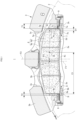
FIG. 1] FIG. 1 is a cross-sectional view taken along a line I-I inFIG. 4 . - [
FIG. 2] FIG. 2 is a virtual view when a friction pad is provided in a pad storage portion by aligning a center of the friction pad with a center of a caliper body. - [
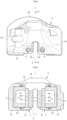
FIG. 3] FIG. 3 is a front view of a disc brake for a vehicle according to a first embodiment of the invention. - [
FIG. 4] FIG. 4 is a side view of the same disc brake for a vehicle. - [
FIG. 5] FIG. 5 is a cross-sectional view taken along a line V-V inFIG. 3 . - [
FIG. 6] FIG. 6 is a perspective view of an outlet-side torque transmitting member and an inlet-side torque transmitting member according to the first embodiment of the invention. - [
FIG. 7] FIG. 7 is a cross-sectional view of a disc brake for a vehicle according to a second embodiment of the invention. - [
FIG. 8] FIG. 8 is a virtual view when a friction pad is provided in a pad storage portion by aligning a center of the friction pad with a center of a caliper body. -
FIGS. 1 to 6 are drawings showing a first embodiment of a disc brake for a vehicle according to the invention. An arrow A indicates a rotation direction of a disc rotor that rotates integrally with a wheel when the vehicle moves forward. A disc outlet side and a disc inlet side as described below are assumed when the vehicle moves forward. - A
disc brake 1 for a vehicle according to the first embodiment includes adisc rotor 2 that rotates integrally with a wheel, a piston-facingcaliper body 3 having a monocoque structure and mounted on a vehicle body on one side portion of thedisc rotor 2, and a pair offriction pads disc rotor 2 sandwiched therebetween betweenaction portions caliper body 3 provided on both side portions of thedisc rotor 2. - The
caliper body 3 integrally includes the pair ofaction portions bridge portion 3b extending over the pair ofaction portions ceiling openings bridge portion 3b. In each of theaction portions 3a, a small-diameter cylinder hole 3d is formed on the disc inlet side, and a large-diameter cylinder hole 3e on the disc outlet side. A small-diameter piston 5a is inserted into the small-diameter cylinder hole 3d, and a large-diameter piston 5b is inserted into the large-diameter cylinder hole 3e.Hydraulic pressure chambers 6 are defined between thecylinder hole 3d and thepiston 5a and between thecylinder hole 3e and thepiston 5b. -
Mounting boss portions action portion 3a provided on an outer side of the vehicle body in a disc circumferential direction. Thecaliper body 3 is mounted on the vehicle body by screwing mounting bolts inserted into mounting bolt insertion holes that are formed in themounting boss portions - A friction
pad storage portion 3g that stores thefriction pad 4 is formed in eachaction portion 3a. The frictionpad storage portion 3g is formed on an inner side with respect to theceiling openings torque receiving surface 3h and a disc outlet-sidetorque receiving surface 3i. Further, an inlet-sidetorque transmitting member 7 that receives a braking torque by abutting against a disc inlet-side end surface 4a of thefriction pad 4 is mounted on the disc inlet-sidetorque receiving surface 3h by abolt 9, and an outlet-sidetorque transmitting member 8 that receives a braking torque by abutting against a disc outlet-side end surface 4b of thefriction pad 4 is mounted on the disc outlet-sidetorque receiving surface 3i by thebolt 9. - The inlet-side
torque transmitting member 7 includes a firsttorque transmitting portion 7a mounted on the disc inlet-sidetorque receiving surface 3h, and a firstpad supporting portion 7b protruding from an end portion of the firsttorque transmitting portion 7a on an inner side in the disc radial direction toward an inner side of the caliper body and supporting a disc radial directioninner side surface 4c of thefriction pad 4, and the firsttorque transmitting portion 7a is formed with a firstfemale screw 7c to which thebolt 9 is attached. The outlet-sidetorque transmitting member 8 includes a secondtorque transmitting portion 8a mounted on the disc outlet-sidetorque receiving surface 3i, and a secondpad supporting portion 8b protruding from an end portion of the secondtorque transmitting portion 8a on an inner side in the disc radial direction toward the inner side of the caliper body and supporting the disc radial directioninner side surface 4c of thefriction pad 4, and the secondtorque transmitting portion 8a is formed with a secondfemale screw portion 8c to which thebolt 9 is attached. Further, a thickness (T1) of the firsttorque transmitting portion 7a of the inlet-sidetorque transmitting member 7 in the disc circumferential direction is larger than a thickness (T2) of the secondtorque transmitting portion 8a of the outlet-sidetorque transmitting member 8 in the disc circumferential direction. - Each of the
friction pads lining 4d in sliding contact with a side surface of thedisc rotor 2, and ametal back plate 4e on which thelining 4d is mounted. Thefriction pad 4 is stored in the frictionpad storage portion 3g in a state in which the disc radial directioninner side surface 4c is supported by the firstpad supporting portion 7b and the secondpad supporting portion 8b, the disc inlet-side end surface 4a faces the firsttorque transmitting portion 7a of the inlet-sidetorque transmitting member 7, and the disc outlet-side end surface 4b faces the secondtorque transmitting portion 8a of the outlet-sidetorque transmitting member 8. A center P1 of thefriction pad 4 is offset from a center P2 of thecaliper body 3 to the disc outlet side. -
FIG. 2 shows a virtual view of the disc brake when thefriction pad 4 is provided in the frictionpad storage portion 3g by aligning the center P1 of thefriction pad 4 with the center P2 of thecaliper body 3, that is, when thefriction pad 4 is provided in the frictionpad storage portion 3g by overlapping a first orthogonal plane F1 passing through the center P1 of thefriction pad 4 and orthogonal to a disc axis with a second orthogonal plane F2 passing through the center P2 of thecaliper body 3 and orthogonal to the disc axis. A comparison between thecaliper body 3 and thefriction pad 4 of thedisc brake 1 according to the first embodiment will be described below. A distance (D2) shown inFIG. 2 indicates a distance between a disc inlet-side end portion 3j of thecylinder hole 3d and the disc inlet-side end surface 4a of thefriction pad 4, and a distance (E2) indicates a distance between a disc outlet-side end portion 3k of thecylinder hole 3d and the disc outlet-side end surface 4b of thefriction pad 4. - In the
disc brake 1 according to the first embodiment, when thefriction pad 4 is provided in the frictionpad storage portion 3g, a distance (D1) between the disc inlet-side end portion 3j of the small-diameter cylinder hole 3d on the disc inlet side and the disc inlet-side end surface 4a of thefriction pad 4 is smaller than the distance (D2). Further, a distance (E1) between the disc outlet-side end portion 3k of thecylinder hole 3d and the disc outlet-side end surface 4b of thefriction pad 4 is larger than the distance (E2). - In the
disc brake 1 for a vehicle formed as described above, the inlet-sidetorque transmitting member 7 and the outlet-sidetorque transmitting member 8 are mounted on the frictionpad storage portion 3g. Accordingly, the center P1 of thefriction pad 4 is offset from the center P2 of thecaliper body 3 to the disc outlet side, and uneven abrasion of thelining 4d can be prevented according to rigidity of thecaliper body 3 or a material of thefriction pad 4. In addition, an offset amount between the center P1 of thefriction pad 4 and the center P2 of thecaliper body 3 can be adjusted using the inlet-sidetorque transmitting member 7 in which the thickness (T1) of the firsttorque transmitting portion 7a in the disc circumferential direction is changed or the outlet-sidetorque transmitting member 8 in which the thickness (T2) of the secondtorque transmitting portion 8a in the disc circumferential direction is changed, the uneven abrasion of thelining 4d of thefriction pad 4 can be favorably prevented without changing a shape of thecaliper body 3 or thefriction pad 4, and there would be no concern in cost increase. - Further, when the first
torque transmitting portion 7a, the firstpad supporting portion 7b, the secondtorque transmitting portion 8a, or the secondpad supporting portion 8b is abrased due to repeating braking, the inlet-sidetorque transmitting member 7 or the outlet-sidetorque transmitting member 8 may be replaced, and thus durability of thecaliper body 3 can be improved. - Since the center P1 of the
friction pad 4 is offset from the center P2 of thecaliper body 3 to the disc outlet side, the small-diameter piston 5a on the disc inlet side presses thefriction pad 4 on the disc inlet side at the time of braking, and the large-diameter piston 5b on the disc outlet side presses thefriction pad 4 on the disc outlet side. Therefore, it is possible to increase a braking force at an initial stage of braking due to a servo effect while preventing the uneven abrasion of thelining 4d according to the rigidity of thecaliper body 3 or the material of thefriction pad 4, and to adjust an operation feeling such that a brake effect at the initial stage of braking is high. - Further, the first
pad supporting portion 7b is integrally formed with the inlet-sidetorque transmitting member 7, and the secondpad supporting portion 8b is integrally formed with the outlet-sidetorque transmitting member 8. Accordingly, the pad supporting portions can be easily formed, and manufacturing costs can be reduced. - Since
FIGS. 7 and8 show a second embodiment of the invention, the same elements as those according to the first embodiment are denoted by the same reference signs, and the detailed description thereof will be omitted. - In the second embodiment, a thickness (T3) of a first
torque transmitting portion 10a of an inlet-sidetorque transmitting member 10 in a disc circumferential direction is larger than a thickness (T4) of a secondtorque transmitting portion 11a of an outlet-sidetorque transmitting member 11 in the disc circumferential direction. - Accordingly, in a state in which the
friction pad 4 is stored in the frictionpad storage portion 3g, the center P1 of thefriction pad 4 is offset from the center P2 of thecaliper body 3 to a disc inlet side. -
FIG. 8 shows a virtual view of the disc brake when thefriction pad 4 is provided in the frictionpad storage portion 3g by aligning the center P1 of thefriction pad 4 with the center P2 of thecaliper body 3, that is, when thefriction pad 4 is provided in the frictionpad storage portion 3g by overlapping the first orthogonal plane F1 with the second orthogonal plane F2. A comparison between thecaliper body 3 and thefriction pad 4 of thedisc brake 1 according to the second embodiment will be described below. A distance (D4) shown inFIG. 8 indicates a distance between the disc inlet-side end portion 3j of thecylinder hole 3d and the disc inlet-side end surface 4a of thefriction pad 4, and a distance (E4) indicates a distance between the disc outlet-side end portion 3k of thecylinder hole 3d and the disc outlet-side end surface 4b of thefriction pad 4. - In the
disc brake 1 according to the second embodiment, when thefriction pad 4 is provided in the frictionpad storage portion 3g, a distance (D3) between the disc inlet-side end portion 3j of the small-diameter cylinder hole 3d on the disc inlet side and the disc inlet-side end surface 4a of thefriction pad 4 is larger than the distance (D4). Further, a distance (E3) between the disc outlet-side end portion 3k of thecylinder hole 3d and the disc outlet-side end surface 4b of thefriction pad 4 is smaller than the distance (E4). - The second embodiment is formed as described above. Accordingly, a pressing force applied from the
piston 5a to thefriction pad 4 on the disc inlet side at the time of braking is reduced, and the large-diameter piston 5b on a disc outlet side presses thefriction pad 4 on the disc outlet side. Therefore, it is possible to prevent a servo effect while preventing uneven abrasion of thelining 4d according to rigidity of thecaliper body 3 or a material of thefriction pad 4, and to adjust an operation feeling to gently apply a braking force from an initial stage of braking. - The disc brake for a vehicle according to the invention is not limited to the disc brake for a vehicle using the piston-facing caliper body having a monocoque structure as in the above-described embodiments, and can also be applied to a disc brake for a vehicle using a split-type piston-facing caliper body. The number of cylinder holes formed in the action portion of the caliper body can be freely set. Further, when the thickness of the first torque transmitting portion in the disc circumferential direction and the thickness of the second torque transmitting portion in the disc circumferential direction are changed, it is also possible to replace the inlet-side torque transmitting member used in the related art with the outlet-side torque transmitting member and to replace the outlet-side torque transmitting member with the inlet-side torque transmitting member.
-
- 1: disc brake for vehicle
- 2: disc rotor
- 3: caliper body
- 3a: action portion
- 3b: bridge portion
- 3c: ceiling opening
- 3d, 3e: cylinder hole
- 3f: mounting boss portion
- 3g: friction pad storage portion
- 3h: disc inlet-side torque receiving surface
- 3i: disc outlet-side torque receiving surface
- 3j: disc inlet-side end portion
- 3k: disc outlet-side end portion
- 4: friction pad
- 4a: disc inlet-side end surface
- 4b: disc outlet-side end surface
- 4c: disc radial direction inner side surface
- 4d: lining
- 4e: back plate
- 5a, 5b: piston
- 6: hydraulic pressure chamber
- 7: inlet-side torque transmitting member
- 7a: first torque transmitting portion
- 7b: first pad supporting portion
- 7c: first female screw portion
- 8: outlet-side torque transmitting member
- 8a: second torque transmitting portion
- 8b: second pad supporting portion
- 8c: second female screw portion
- 9: bolt
- 10: inlet-side torque transmitting member
- 10a: first torque transmitting portion
- 11: outlet-side torque transmitting member
- 11a: second torque transmitting portion
Claims (6)
- A disc brake for a vehicle in which a caliper body is formed by connecting, by a bridge portion extending over an outer circumference of a disc rotor, a pair of action portions each having a cylinder hole for storing a piston, and in which friction pad storage portions are formed in the action portions to store a pair of friction pads provided on both side portions of the disc rotor, whereineach friction pad storage portion includes a disc inlet-side torque receiving surface that faces a disc inlet-side end surface of the friction pad when the vehicle moves forward, and a disc outlet-side torque receiving surface that faces a disc outlet-side end surface of the friction pad when the vehicle moves forward,an inlet-side torque transmitting member configured to receive a braking torque by abutting against the disc inlet-side end surface of the friction pad is mounted on the disc inlet-side torque receiving surface,an outlet-side torque transmitting member configured to receive a braking torque by abutting against the disc outlet-side end surface of the friction pad is mounted on the disc outlet-side torque receiving surface, anda thickness of the inlet-side torque transmitting member in a disc circumferential direction differs from a thickness of the outlet-side torque transmitting member in the disc circumferential direction, and a center of the friction pad is offset from a center of the caliper body in the disc circumferential direction.
- The disc brake for a vehicle according to claim 1, wherein
the thickness of the inlet-side torque transmitting member in the disc circumferential direction is larger than the thickness of the outlet-side torque transmitting member in the disc circumferential direction, and the center of the friction pad is offset from the center of the caliper body to a disc outlet side. - The disc brake for a vehicle according to claim 1, wherein
the thickness of the outlet-side torque transmitting member in the disc circumferential direction is larger than the thickness of the inlet-side torque transmitting member in the disc circumferential direction, and the center of the friction pad is offset from the center of the caliper body to a disc inlet side. - The disc brake for a vehicle according to any one of claims 1 to 3, wherein
the caliper body is formed with a plurality of cylinder holes facing the pair of action portions. - The disc brake for a vehicle according to claim 4, wherein
the cylinder hole on the disc outlet side has a diameter larger than that of the other cylinder hole. - The disc brake for a vehicle according to any one of claims 1 to 5, wherein
each of the outlet-side torque transmitting member and the inlet-side torque transmitting member includes a pad supporting portion protruding from an end portion on an inner side in a disc radial direction toward an inner side of the caliper body and configured to support a disc radial direction inner side surface of the friction pad.
Applications Claiming Priority (2)
| Application Number | Priority Date | Filing Date | Title |
|---|---|---|---|
| JP2020158241 | 2020-09-23 | ||
| PCT/JP2021/034642 WO2022065319A1 (en) | 2020-09-23 | 2021-09-21 | Disc brake for vehicle |
Publications (2)
| Publication Number | Publication Date |
|---|---|
| EP4219975A1 true EP4219975A1 (en) | 2023-08-02 |
| EP4219975A4 EP4219975A4 (en) | 2024-11-13 |
Family
ID=80845437
Family Applications (1)
| Application Number | Title | Priority Date | Filing Date |
|---|---|---|---|
| EP21872448.2A Pending EP4219975A4 (en) | 2020-09-23 | 2021-09-21 | DISC BRAKE FOR A VEHICLE |
Country Status (4)
| Country | Link |
|---|---|
| US (1) | US12535109B2 (en) |
| EP (1) | EP4219975A4 (en) |
| JP (1) | JP7805941B2 (en) |
| WO (1) | WO2022065319A1 (en) |
Family Cites Families (11)
| Publication number | Priority date | Publication date | Assignee | Title |
|---|---|---|---|---|
| JPH0925963A (en) | 1995-07-14 | 1997-01-28 | Nissin Kogyo Kk | Piston-opposed disc brakes for vehicles |
| JP3576772B2 (en) * | 1997-10-08 | 2004-10-13 | 日産自動車株式会社 | Disc brake |
| US6668983B2 (en) * | 2001-12-18 | 2003-12-30 | Delphi Technologies, Inc. | Wheel brake caliper with integral brake pad torque sensing |
| JP2007100748A (en) | 2005-09-30 | 2007-04-19 | Hitachi Ltd | Disc brake |
| JP2008196683A (en) * | 2006-06-29 | 2008-08-28 | Akebono Brake Ind Co Ltd | Disc brake |
| JP2008144891A (en) * | 2006-12-12 | 2008-06-26 | Advics:Kk | Disk brake |
| JP5084753B2 (en) * | 2009-01-08 | 2012-11-28 | 日信工業株式会社 | Caliper body manufacturing method and caliper body for disc brake for vehicle |
| JP5706801B2 (en) | 2011-11-14 | 2015-04-22 | 日信工業株式会社 | Vehicle disc brake |
| JP2014190478A (en) * | 2013-03-28 | 2014-10-06 | Advics Co Ltd | Disc brake device |
| JP6446275B2 (en) * | 2015-01-19 | 2018-12-26 | 曙ブレーキ工業株式会社 | Counter-piston disc brake caliper |
| US11209057B2 (en) | 2018-01-12 | 2021-12-28 | Performance Friction Corporation | Torsion brake retractor, caliper and method |
-
2021
- 2021-09-21 US US18/027,570 patent/US12535109B2/en active Active
- 2021-09-21 JP JP2022552003A patent/JP7805941B2/en active Active
- 2021-09-21 WO PCT/JP2021/034642 patent/WO2022065319A1/en not_active Ceased
- 2021-09-21 EP EP21872448.2A patent/EP4219975A4/en active Pending
Also Published As
| Publication number | Publication date |
|---|---|
| JP7805941B2 (en) | 2026-01-26 |
| US12535109B2 (en) | 2026-01-27 |
| EP4219975A4 (en) | 2024-11-13 |
| US20230375051A1 (en) | 2023-11-23 |
| WO2022065319A1 (en) | 2022-03-31 |
| JPWO2022065319A1 (en) | 2022-03-31 |
Similar Documents
| Publication | Publication Date | Title |
|---|---|---|
| US8925690B2 (en) | Disc brake apparatus | |
| US20120043168A1 (en) | Brake systems, caliper assemblies and pads incorporating differential abutments | |
| US9279465B2 (en) | Disc brake pad assembly | |
| EP3809009B1 (en) | Vehicular disc brake | |
| CN121358970A (en) | Single pneumatic disc brake tappet with features simulating multiple tappets | |
| JP7110049B2 (en) | Disc brake pad spring and disc brake device | |
| US6223867B1 (en) | Disk brake | |
| CN121358969A (en) | Pneumatic disc brake tappet and brake block backplate with interface features | |
| EP2796742B1 (en) | Caliper body for vehicle disc brake | |
| US12535109B2 (en) | Disc brake for vehicle | |
| JP4866873B2 (en) | Vehicle disc brake | |
| JP5879032B2 (en) | Disc brake | |
| JP2020056486A (en) | Disc brake | |
| JP4250117B2 (en) | Pin slide type vehicle disc brake | |
| US20240263679A1 (en) | Disc brake and pad spring | |
| JP5087497B2 (en) | Disc brake | |
| JP4928478B2 (en) | Disc brake | |
| WO2019189506A1 (en) | Floating-type disk brake | |
| JP2009008113A (en) | Disc brake | |
| JP4871920B2 (en) | Disc brake | |
| JP4319046B2 (en) | Motorcycle brake equipment | |
| US12270442B2 (en) | Pad clip for disc brake apparatus and disc brake apparatus | |
| JP7109954B2 (en) | disc brake pads | |
| JPH09329162A (en) | Disc brake device | |
| JP6560082B2 (en) | Vehicle disc brake |
Legal Events
| Date | Code | Title | Description |
|---|---|---|---|
| STAA | Information on the status of an ep patent application or granted ep patent |
Free format text: STATUS: THE INTERNATIONAL PUBLICATION HAS BEEN MADE |
|
| PUAI | Public reference made under article 153(3) epc to a published international application that has entered the european phase |
Free format text: ORIGINAL CODE: 0009012 |
|
| STAA | Information on the status of an ep patent application or granted ep patent |
Free format text: STATUS: REQUEST FOR EXAMINATION WAS MADE |
|
| 17P | Request for examination filed |
Effective date: 20230316 |
|
| AK | Designated contracting states |
Kind code of ref document: A1 Designated state(s): AL AT BE BG CH CY CZ DE DK EE ES FI FR GB GR HR HU IE IS IT LI LT LU LV MC MK MT NL NO PL PT RO RS SE SI SK SM TR |
|
| DAV | Request for validation of the european patent (deleted) | ||
| DAX | Request for extension of the european patent (deleted) | ||
| A4 | Supplementary search report drawn up and despatched |
Effective date: 20241010 |
|
| RIC1 | Information provided on ipc code assigned before grant |
Ipc: F16D 55/228 20060101ALI20241007BHEP Ipc: F16D 65/095 20060101AFI20241007BHEP |
|
| RAP3 | Party data changed (applicant data changed or rights of an application transferred) |
Owner name: ASTEMO, LTD. |