EP4219929A1 - Internal combustion engine and transportation device - Google Patents
Internal combustion engine and transportation device Download PDFInfo
- Publication number
- EP4219929A1 EP4219929A1 EP21957737.6A EP21957737A EP4219929A1 EP 4219929 A1 EP4219929 A1 EP 4219929A1 EP 21957737 A EP21957737 A EP 21957737A EP 4219929 A1 EP4219929 A1 EP 4219929A1
- Authority
- EP
- European Patent Office
- Prior art keywords
- piston
- sliding surface
- primary
- crystal silicon
- silicon grains
- Prior art date
- Legal status (The legal status is an assumption and is not a legal conclusion. Google has not performed a legal analysis and makes no representation as to the accuracy of the status listed.)
- Granted
Links
Images






Classifications
-
- F—MECHANICAL ENGINEERING; LIGHTING; HEATING; WEAPONS; BLASTING
- F02—COMBUSTION ENGINES; HOT-GAS OR COMBUSTION-PRODUCT ENGINE PLANTS
- F02F—CYLINDERS, PISTONS OR CASINGS, FOR COMBUSTION ENGINES; ARRANGEMENTS OF SEALINGS IN COMBUSTION ENGINES
- F02F1/00—Cylinders; Cylinder heads
- F02F1/18—Other cylinders
-
- F—MECHANICAL ENGINEERING; LIGHTING; HEATING; WEAPONS; BLASTING
- F05—INDEXING SCHEMES RELATING TO ENGINES OR PUMPS IN VARIOUS SUBCLASSES OF CLASSES F01-F04
- F05C—INDEXING SCHEME RELATING TO MATERIALS, MATERIAL PROPERTIES OR MATERIAL CHARACTERISTICS FOR MACHINES, ENGINES OR PUMPS OTHER THAN NON-POSITIVE-DISPLACEMENT MACHINES OR ENGINES
- F05C2201/00—Metals
- F05C2201/90—Alloys not otherwise provided for
- F05C2201/903—Aluminium alloy, e.g. AlCuMgPb F34,37
Definitions
- the present disclosure relates to an internal combustion engine, and specifically to an internal combustion engine including a cylinder block formed of an aluminum alloy containing silicon, and also relates to a transportation vehicle including such an internal combustion engine.
- an aluminum alloy has been used more and more widely to form cylinder blocks. Cylinder blocks are required to have a high wear resistance. Therefore, an aluminum alloy containing a high content of silicon, namely, an aluminum-silicon-based alloy having a hyper eutectic composition is considered promising as an aluminum alloy for cylinder blocks.
- silicon crystal grains located at a sliding surface contribute to improvement in the wear resistance.
- Such a cylinder block formed of an aluminum-silicon-based alloy is disclosed in, for example, Patent Document No. 1.
- a mesh-like groove referred to as a cross hatch is generally formed in a surface of a cylinder wall defining a cylinder bore. Oil (lubricant oil) is retained in the cross hatch, and thus a state where the cylinder wall and a piston skirt or a piston ring operate smoothly with respect to each other may be kept. This may suppress wear and seizure.
- Patent Document No. 1 WO2004/002658
- An embodiment of the present invention made in light of the above-described problems has an object of, in an internal combustion engine including a cylinder block formed of an aluminum alloy containing silicon, decreasing the friction resistance of a cylinder wall and the consumption amount of oil while providing a certain level of seizure resistance with certainty.
- An internal combustion engine including:
- the ten-point average surface roughness Rz JIS of the sliding surface of the cylinder wall is 0.5 ⁇ m or smaller.
- the sliding surface has projected and recessed portions that are sufficiently small to cause the sliding surface to be considered as being mirror-finished. Therefore, a uniform oil film is formed at the sliding surface, which may decrease the friction resistance. This may decrease the sliding loss and improve the fuel efficiency.
- oil (lubricant oil) remaining in the surface of the cylinder wall is decreased in the amount as a result of being scraped off by a piston ring. This decreases the consumption amount of the oil and suppresses deterioration in performance of a catalyst.
- the small size of the projected and recessed portions at the sliding surface decreases aggressiveness of the cylinder wall to other members (aggressiveness to piston rings and a piston skirt).
- the primary-crystal silicon grains which are highly hard, are present at the sliding surface. Therefore, the surface pressure applied to an alloy substrate (matrix) is decreased, and thus a sufficient level of seizure resistance may be guaranteed.
- a groove such as a cross hatch is not necessary, and thus the oil may be prevented from escaping into the groove. Therefore, the oil film has a higher pressure and a fluid lubrication state is preferably realized. This also guarantees a certain level of seizure resistance.
- the crushing ratio of the primary-crystal silicon grains at the sliding surface of the cylinder wall is 200 or lower. Therefore, a large number of the primary-crystal silicon grains that are not crushed (that may be considered "healthy") are exposed at the sliding surface. This also decreases the aggressiveness to the other members. In addition, the contact load with the piston skirt and the piston rings is dispersed in the exposed healthy primary-crystal silicon grains, which improves the seizure resistance and the wear resistance of the cylinder wall.
- the projected and recessed portions at the sliding surface are small. Therefore, a uniform oil film is formed at the sliding surface, which may decrease the friction resistance. This may decrease the sliding loss and improve the fuel efficiency.
- the oil remaining in the surface of the cylinder wall is decreased in the amount as a result of being scraped off by the piston ring. This decreases the consumption amount of the oil and suppresses deterioration in performance of a catalyst.
- the small size of the projected and recessed portions at the sliding surface decreases the aggressiveness of the cylinder wall to the other members (aggressiveness to the piston rings and the piston skirt).
- the internal combustion engine of item 1 or 2 wherein the plurality of primary-crystal silicon grains have an area size occupying a ratio of 8% or higher of an area size of the sliding surface.
- the surface pressure applied to the alloy substrate is decreased, which improves the seizure resistance and the wear resistance.
- the "blank ratio" is an index indicating how the primary-crystal silicon grains are dispersed. A lower blank ratio indicates that the primary-crystal silicon grains are better dispersed. In the case where the blank ratio of the sliding surface is 55.5% or lower, the surface pressure applied to the alloy substrate is sufficiently decreased. Therefore, the seizure resistance and the wear resistance are improved.
- the aluminum alloy as the material of the cylinder block preferably contains silicon at a content of 15% by mass or higher and 25% by mass or lower.
- the silicon content is 15% by mass or higher, a sufficiently large amount of the primary-crystal silicon grains may be deposited, which may sufficiently improve the wear resistance of the cylinder block.
- the strength of the cylinder block may be kept sufficiently high.
- the primary-crystal silicon grains have an average grain diameter in the range of 8 ⁇ m or longer and 50 ⁇ m or shorter. In this case, the wear resistance of the cylinder block may be further improved.
- the average grain diameter of the primary-crystal silicon grains is longer than 50 ⁇ m, the number of the primary-crystal silicon grains per unit area size of the sliding surface is small. Therefore, a large load is applied to each of the primary-crystal silicon grains while the engine is operated, and the primary-crystal silicon grains may possibly be crushed.
- the crushed pieces of the primary-crystal silicon grains act undesirably as polishing particles, which causes a risk that the sliding surface is significantly worn.
- the average grain diameter of the primary-crystal silicon grains is shorter than 8 ⁇ m, merely a small part of the primary-crystal silicon grains is embedded in the matrix. Therefore, the primary-crystal silicon grains easily fall while the engine is operated.
- the primary-crystal silicon grains that have fallen act undesirably as polishing particles, which causes a risk that the sliding surface is significantly worn.
- the primary-crystal silicon grains are present in a sufficient number per unit area size of the sliding surface. Therefore, the load applied to each of the primary-crystal silicon grains while the engine is operated is relatively small, which suppresses the crushing of the primary-crystal silicon grains. Since the part of the primary-crystal silicon grains that is embedded in the matrix is sufficiently large, the fall of the primary-crystal silicon grains is suppressed. Therefore, the wear of the sliding surface by the primary-crystal silicon grains that have fallen is suppressed.
- each of the plurality of piston rings includes the diamond-like carbon layer on the outer circumferential portion thereof, the cylinder wall may be prevented with more certainty from being scuffed by the piston rings.
- the wear resistance and the seizure resistance of the piston may be improved.
- a transportation vehicle comprising the internal combustion engine of any one of items 1 through 8.
- the internal combustion engine according to an embodiment of the present invention is preferably usable in any of various types of transportation vehicles.
- the friction resistance of a cylinder wall and the consumption amount of oil may be decreased while a certain level of seizure resistance is provided with certainty.
- FIG. 1 shows an engine (internal combustion engine) 100 according to an embodiment of the present invention.
- FIG. 1 is a cross-sectional view schematically showing the engine 100.
- the engine 100 includes a cylinder block 10, a cylinder head 20, and a crankcase 30.
- the engine 100 further includes a piston 40, a crankshaft 50, and a con rod (connecting rod) 60.
- a direction from the cylinder block 10 toward the cylinder head 20 is an "upward direction” and a direction from the cylinder block 10 toward the crankcase 30 is a "downward direction”.
- the cylinder block (may also be referred to as a "cylinder body") 10 includes a cylinder wall 12 and an outer wall 13.
- the cylinder wall 12 is formed to define a cylinder bore 11.
- the outer wall 13 surrounds the cylinder wall 12 and forms an outer enclosure of the cylinder block 10.
- a water jacket 14 holding cooling water is provided between the cylinder wall 12 and the outer wall 13.
- the cylinder head 20 is provided above the cylinder block 10.
- the cylinder head 20 defines a combustion chamber 70 together with the cylinder wall 12 and the piston 40.
- the cylinder head 20 includes an intake port 21, through which fuel is to be introduced into the combustion chamber 70, and an exhaust port 22, through which exhaust gas is to be discharged from the combustion chamber 70.
- An intake valve 23 is provided in the intake port 21, and an exhaust valve 24 is provided in the exhaust port 22.
- crankcase 30 is provided below the cylinder block 10. Namely, the crankcase 30 is located so as to be on the side opposite to the cylinder head 20 with the cylinder block 10 being located therebetween.
- the crankcase 30 may be separate from, or may be integrally formed with, the cylinder block 10.
- the piston 40 is accommodated in the cylinder bore 11.
- no cylinder sleeve is fit into the cylinder bore 11. Therefore, the piston 40 moves up and down in a reciprocating manner in the cylinder bore 11 while being in contact with an inner circumferential surface (cylinder bore 11 -side surface) 12a of the cylinder wall 12.
- the inner circumferential surface 12a of the cylinder wall 12 is a sliding surface along which the piston 40 is slidable.
- the crankshaft 50 is accommodated in the crankcase 30.
- the crankshaft 50 includes a crankpin 51 and a crank arm 52.
- the con rod 60 includes a rod main body 61 having a rod-like shape, a small end portion 62 provided at one end of the rod main body 61, and a large end portion 63 provided at the other end of the rod main body 61.
- the con rod 60 connects the piston 40 and the crankshaft 50 to each other. Specifically, a piston pin 48 of the piston 40 is inserted into a through-hole (piston pin hole) of the small end portion 62, and the crankpin 51 of the crankshaft 50 is inserted into a through-hole (crankpin hole) of the large end portion 63.
- This structure connects the piston 40 and the crankshaft 50 to each other.
- a bearing 66 is provided between an inner circumferential surface of the large end portion 63 and the crankpin 51.
- FIG. 2 is a side view schematically showing the piston 40 of the engine 100.
- the piston 40 (more specifically, a piston main body 41 described below) is formed of an aluminum alloy.
- the piston 40 may be formed by forging or casting.
- the piston 40 includes the piston main body 41 and a plurality of piston rings 42.
- the piston main body 41 includes a piston head 43 and a piston skirt 44.
- the piston head 43 is located at a top end of the piston 40. Ring grooves holding the piston rings 42 are formed in an outer circumferential portion of the piston head 43.
- the piston skirt 44 extends downward from the outer circumferential portion of the piston head 43.
- the piston rings 42 are attached to an outer circumferential portion of the piston main body 41, more specifically, to the outer circumferential portion of the piston head 43.
- the piston 40 includes three piston rings 42.
- the number of the piston rings 42 is not limited to three.
- the piston rings at a top position and at a central position (a top ring and a second ring) 42a and 42b, for example, are compression rings that keep the combustion chamber 70 in an airtight state.
- the piston ring at a bottom position (third ring) 42c is an oil ring that scrapes off extra oil attached to the cylinder wall 12.
- the piston rings 42 are formed of a metal material (e.g., steel).
- FIG. 3 is a perspective view schematically showing the cylinder block 10 of the engine 100.
- the cylinder block 10 includes the cylinder wall 12 including the sliding surface 12a, and the outer wall 13.
- the water jacket 14 is provided between the cylinder wall 12 and the outer wall 13.
- the cylinder block 10 is formed of an aluminum alloy containing silicon. More specifically, the cylinder block 10 is formed of an aluminum-silicon-based alloy having a hyper eutectic composition.
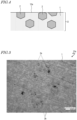
- FIG. 4 is a cross-sectional view schematically showing the sliding surface 12a of the cylinder wall 12 and the vicinity thereof.
- the cylinder wall 12 of the cylinder block 10 includes an aluminum-containing solid-solution matrix (alloy substrate) 1 and a plurality of primary-crystal silicon grains 2 dispersed in the matrix 1. Some of the primary-crystal silicon grains 2 are exposed to the sliding surface 12a. Namely, the cylinder block 10 includes the primary-crystal silicon grains 2 at the sliding surface 12a.
- the cylinder wall 12 further includes a plurality of eutectic silicon grains dispersed in the matrix 1. Therefore, the cylinder block 10 may further include the eutectic silicon grains at the sliding surface 12a.
- a molten aluminum-silicon-based alloy having a hyper eutectic composition is cooled, relatively large silicon crystal grains are deposited first and then relatively small silicon crystal grains are deposited.
- the relatively large silicon crystal grains are the "primary-crystal silicon grains", and the relatively small silicon crystal grains are the "eutectic silicon grains”.
- the cylinder block 10 is formed such that the sliding surface 12a has a ten-point average surface roughness Rz JIS in a predetermined range.
- the ten-point average surface roughness Rz JIS of the sliding surface 12a is 0.5 ⁇ m or smaller in generally the entirety of the sliding surface 12a.
- the ten-point average surface roughness Rz JIS is of a certain reference length of a profile curve, and is a difference between an average value of elevations of the highest peak through the fifth highest peak R1, R3, R5, R7 and R9, and an average value of elevations of the lowest trough through the fifth lowest trough R2, R4, R6, R8 and R10.
- the ten-point average surface roughness Rz JIS may be measured by use of a surface roughness meter (e.g., Surfcom 1400D produced by Tokyo Seimitsu Co., Ltd.).
- Rz JIS R1 + R2 + R3 + R4 + R5 ⁇ R2 + R4 + R6 + R8 + R10 / 5
- the cylinder block 10 is formed such that the primary-crystal silicon grains 2 at the sliding surface 12a are crushed at a crushing ratio in a predetermined range.
- the crushing ratio of the primary-crystal silicon grains 2 at the sliding surface 12a is 200 or lower in generally the entirety of the sliding surface 12a.
- the crushing ratio of the primary-crystal silicon grains 2 is a ratio, represented by percentage, of the area size of the crushed part of the primary-crystal silicon grains 2 with respect to the area size of the primary-crystal silicon grains 2 at the sliding surface 12a. A specific method for measuring the crushing ratio will be described below.
- the ten-point average surface roughness Rz JIS of the sliding surface 12a of the cylinder wall 12 is 0.5 ⁇ m or smaller.
- the sliding surface 12a has projected and recessed portions that are sufficiently small to cause the sliding surface 12a to be considered as being mirror-finished. Therefore, a uniform oil film is formed at the sliding surface 12a, which may decrease the friction resistance. This may decrease the sliding loss and improve the fuel efficiency.
- oil (lubricant oil) remaining in the surface of the cylinder wall 12 is decreased in the amount as a result of being scraped off by the piston ring 42. This decreases the consumption amount of the oil and suppresses deterioration in performance of a catalyst.
- the small size of the projected and recessed portions at the sliding surface 12a decreases aggressiveness of the cylinder wall 12 to other members (aggressiveness to the piston rings 42 and the piston skirt 44).
- the ten-point average surface roughness Rz JIS of the sliding surface 12a is more preferably 0.3 ⁇ m or smaller.
- the seizure resistance may be decreased.
- the primary-crystal silicon grains 2, which are highly hard are present at the sliding surface 12a. Therefore, the surface pressure applied to the alloy substrate (matrix) 1 is decreased, and thus a sufficient level of seizure resistance may be guaranteed.
- a groove such as a cross hatch is not necessary, and thus the oil may be prevented from escaping into the groove. Therefore, the oil film has a higher pressure and a fluid lubrication state is preferably realized. This also guarantees a certain level of seizure resistance.
- the crushing ratio of the primary-crystal silicon grains 2 at the sliding surface 12a of the cylinder wall 12 is 200 or lower. Therefore, a large number of the primary-crystal silicon grains 2 that are not crushed (that may be considered "healthy") are exposed at the sliding surface 12a. This also decreases the aggressiveness to the other members. In addition, the contact load with the piston skirt 44 and the piston rings 42 is dispersed in the exposed healthy primary-crystal silicon grains 2, which improves the seizure resistance and the wear resistance of the cylinder wall 12.
- the crushing ratio of the primary-crystal silicon grains 2 may be measured as follows, for example.
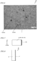
- FIG. 5 shows an example of the image of the sliding surface 12a.
- crushed parts 2a of the primary-crystal silicon grains 2 and non-crushed parts 2b of the primary-crystal silicon grains 2 are present at the sliding surface 12a.
- an area size S1 of the crushed parts 2a of the primary-crystal silicon grains 2 is found by binarization using image analysis software.
- the crushed parts 2a have a black external appearance, and thus may be distinguished by binarization from the non-crushed parts 2b and the alloy substrate 1.
- the surface roughness of the sliding surface 12a of the cylinder wall 12 may also be represented by, for example, an arithmetic average roughness Ra.
- the sliding surface 12a has an arithmetic average roughness Ra that is, for example, lower than 0.05 ⁇ m.
- the ratio of the area size occupied by the primary-crystal silicon grains 2 with respect to the area size of the sliding surface 12a is preferably 8% or higher. In the case where the ratio of the area size occupied by the primary-crystal silicon grains 2 with respect to the area size of the sliding surface 12a is 8% or higher, the surface pressure applied to the alloy substrate 1 is decreased, which improves the seizure resistance and the wear resistance.
- the sliding surface 12a may also be evaluated by a "blank ratio".
- FIG. 6 is a view provided to illustrate the definition of the "blank ratio”. As shown in FIG. 6 , the sliding surface 12a is divided into a plurality of grids Sq each having a size of 0.1 mm ⁇ 0.1 mm. These grids Sq naturally include grids Sq1, where the primary-crystal silicon grains 2 are present, and grids Sq2, where the primary-crystal silicon grains 2 are not present.
- the "blank ratio” is the ratio (percentage) of the number of the grids Sq2 with no primary-crystal silicon grains 2 with respect to the total number of the grids Sq.
- the "blank ratio" may be considered as an index indicating how the primary-crystal silicon grains 2 are dispersed.
- a lower blank ratio indicates that the primary-crystal silicon grains 2 are better dispersed.
- the surface pressure applied to the alloy substrate 1 is sufficiently decreased. Therefore, the seizure resistance and the wear resistance are improved.
- the aluminum alloy as the material of the cylinder block 10 preferably contains silicon at a content of 15% by mass or higher and 25% by mass or lower.
- the silicon content is 15% by mass or higher, a sufficiently large amount of the primary-crystal silicon grains 2 may be deposited, which may sufficiently improve the wear resistance of the cylinder block 10.
- the strength of the cylinder block 10 may be kept sufficiently high.
- the primary-crystal silicon grains 2 have an average grain diameter in the range of 8 ⁇ m or longer and 50 ⁇ m or shorter. In this case, the wear resistance of the cylinder block 10 may be further improved. In the case where the average grain diameter of the primary-crystal silicon grains 2 is longer than 50 ⁇ m, the number of the primary-crystal silicon grains 2 per unit area size of the sliding surface 12a is small. Therefore, a large load is applied to each of the primary-crystal silicon grains 2 while the engine 100 is operated, and the primary-crystal silicon grains 2 may possibly be crushed. The crushed pieces of the primary-crystal silicon grains 2 act undesirably as polishing particles, which causes a risk that the sliding surface 12a is significantly worn.
- the average grain diameter of the primary-crystal silicon grains 2 is shorter than 8 ⁇ m, merely a small part of the primary-crystal silicon grains 2 is embedded in the matrix 1. Therefore, the primary-crystal silicon grains 2 easily fall while the engine 100 is operated.
- the primary-crystal silicon grains 2 that have fallen act undesirably as polishing particles, which causes a risk that the sliding surface 12a is significantly worn.
- the primary-crystal silicon grains 2 are present in a sufficient number per unit area size of the sliding surface 12a. Therefore, the load applied to each of the primary-crystal silicon grains 2 while the engine 100 is operated is relatively small, which suppresses the crushing of the primary-crystal silicon grains 2. Since the part of the primary-crystal silicon grains 2 that is embedded in the matrix 1 is sufficiently large, the fall of the primary-crystal silicon grains 2 is suppressed. Therefore, the wear of the sliding surface 12a by the primary-crystal silicon grains 2 that have fallen is suppressed.
- the eutectic silicon grains have an average grain diameter shorter than that of the primary-crystal silicon grains 2.
- the average grain diameter of the eutectic silicon grains is, for example, 7.5 ⁇ m or shorter.
- the average grain diameters of the primary-crystal silicon grains 2 and the eutectic silicon grains may be measured as follows by image processing performed on an image of the sliding surface 12a. First, a diameter (equivalent diameter) of each of the silicon crystal grains with an assumption that the silicon crystal grains are of a true circle is calculated based on an area size of each silicon crystal grain obtained by the image processing. As a result, the number (frequency) and the diameters of the silicon crystal grains are specified. Tiny crystal grains each having a diameter shorter than 1 ⁇ m are not counted as silicon crystal grains. Based on the calculated number (frequency) and the calculated diameters of the silicon crystal grains, a grain size distribution of the silicon crystal grains is obtained. The obtained grain size distribution (histogram) includes two peaks.
- the grain size distribution is divided into two regions with the threshold being a diameter of a portion forming a trough between the two peaks.
- the region corresponding to longer diameters is set as the grain size distribution of the primary-crystal silicon grains, and the region corresponding to shorter diameters is set as the grain size distribution of the eutectic silicon grains.
- the average crystal diameter of the primary-crystal silicon grains and the average crystal diameter of the eutectic silicon grains may be calculated.
- FIG. 7 is a cross-sectional view showing an example of structure of the piston ring 42 of the piston 40.
- a diamond-like carbon layer hereinafter, referred to as a "DLC layer" 42D is formed on an outer circumferential portion (outer circumferential surface) of the piston ring 42.
- the outer circumferential portion of the piston ring 42 is a portion to be in contact with the cylinder wall 12.
- the piston ring 42 does not need to include the DLC layer 42D.
- the DLC layer 42D formed on the outer circumferential surface of each of the piston rings 42 may prevent, with more certainty, the cylinder wall 12 from being scuffed by the piston rings 42.
- the DLC layer 42D is preferably formed by a deposition method (e.g., a CVD method or a PVD method) .
- the DLC layer 42D may have any composition or a thickness with no specific limitation. From the point of view of preventing the scuffing with more certainty, the thickness of the DLC layer 42D is preferably 2 ⁇ m or greater. From the point of view of the adhesiveness, the thickness of the DLC layer 42D is preferably 20 ⁇ m or less.
- FIG. 8 is a cross-sectional view showing an example of structure of the piston skirt 44.
- the piston skirt 44 includes a resin layer rl formed on at least a part of an outer circumferential surface thereof.
- the resin layer rl is provided on a substrate bl formed of an aluminum alloy.
- the resin layer rl includes, for example, a polymer matrix and solid lubricant particles dispersed in the polymer matrix.
- a material of the polymer matrix thermosetting polyamideimide, for example, is preferably usable.
- the material of the polymer matrix is not limited to this.
- the solid lubricant particles any of various known types of solid lubricant particles may be used. For example, graphite particles and molybdenum disulfide particles are preferably usable.
- the resin layer rl may be formed by, for example, applying a liquid resin material to the piston skirt 44 by a spray method or any of various printing methods (a screen printing method, a pad printing method or the like).
- the wear resistance and the seizure resistance of the piston 40 may be improved.
- the piston skirt 44 may include a plating layer (e.g., iron-plating layer) instead of the resin layer rl. Also in the case where the piston skirt 44 includes the plating layer formed on at least a part of the outer circumferential surface thereof, the wear resistance and the seizure resistance of the piston 40 may be improved. The piston skirt 44 may not need to include either the resin layer rl or the plating layer.
- a plating layer e.g., iron-plating layer
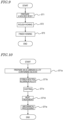
- FIG. 9 and FIG. 10 are flowcharts showing production steps of the cylinder block 10.
- a molded body formed of an aluminum alloy containing silicon is prepared (step ST1).
- This molded body includes primary-crystal silicon grains and eutectic silicon grains at, and in the vicinity of, a surface thereof.
- the step ST1 of preparing the molded body includes, for example, steps ST1a through ST1e shown in FIG. 10 .
- an aluminum alloy containing silicon is prepared (step ST1a).
- the content of silicon in the aluminum alloy is preferably 15% by mass or higher and 25% by mass or lower.
- the aluminum alloy contains aluminum at a content of, for example, 73.4% by mass or higher and 79.6% by mass or lower.
- the aluminum alloy may contain copper. In this case, the aluminum alloy contains copper at a content of, for example, 2.0% by mass or higher and 5.0% by mass or lower.
- the prepared aluminum alloy is heated in a melting furnace to be melted and thus a molten aluminum alloy is formed (step ST1b).
- About 100 ppm by mass of phosphorus may be incorporated into the pre-melting aluminum alloy or the molten aluminum alloy.
- the aluminum alloy contains phosphorus at a content of 50 ppm by mass or higher and 200 ppm by mass or lower, increase in the size of the silicon crystal grains may be suppressed. Therefore, the silicon crystal grains may be dispersed uniformly in the alloy.
- the aluminum alloy may contain calcium at a content of 0.01% by mass or lower.
- the aluminum alloy contains phosphorus at a content of 50 ppm by mass or higher and 200 ppm by mass or lower and calcium at a content of 0.01% by mass or lower.
- the molten aluminum alloy is used to perform casting (specifically, high-pressure dis-casting) (step ST1c). Namely, the molten aluminum alloy is cooled in a casting mold to form a molded body. In this step, a portion to be the sliding surface 12a of the cylinder wall 12 is cooled at a high cooling rate (e.g., 4°C/second or higher and 50°C/second or lower). In this manner, a molded body including the silicon crystal grains, contributing to the wear resistance, at, and in the vicinity of, a surface thereof is obtained.
- the casting step ST1c may be performed by use of a casting device disclosed in, for example, WO2004/002658 .
- the molded body removed from the casting mold is subjected to one of heat treatments referred to as "T5", "T6” and “T7” (step ST1d).
- T5 treatment the molded body is, immediately after being removed from the casting mold, for example, washed with water or the like to be quenched, then is subjected to artificial aging at a predetermined temperature for a predetermined time period in order to improve the mechanical properties thereof and to stabilize the size thereof, and then is cooled with air.
- the molded body is, after being removed from the casting mold, subjected to a solution treatment at a predetermined temperature for a predetermined time period, then is cooled with water, then is subjected to artificial aging at a predetermined temperature for a predetermined time period, and then is cooled with air.
- the molded body is subjected to artificial aging more excessively than according to the T6 treatment.
- the T7 treatment may stabilize the size more than the T6 treatment, but results in a lower hardness than the T6 treatment.
- step ST1e a surface of the molded body to be in contact with the cylinder head 20 or the crankcase 30 is, for example, shaved.
- an inner circumferential surface of a portion, of the molded body, to become the cylinder wall is subjected to a first honing process (referred to as a "rough honing process") (step ST2).
- a first honing process referred to as a "rough honing process”
- the inner circumferential surface is polished with a whetstone having a relatively small number of grit size (e.g., #600 diamond whetstone).
- the inner circumferential surface is subjected to a second honing process (referred to as a "finish honing process") (step ST3).
- the inner circumferential surface is polished with a whetstone having a larger number of grit size than used in the rough honing process (e.g., with a #3000 diamond whetstone).
- the rough honing process and the finish honing process may be performed by use of a honing device disclosed in, for example, Japanese Laid-Open Patent Publication No. 2004-268179 .
- the number of times of honing process is not limited to two as described above.
- the grit size of the whetstone to be used in the honing processes may be adjusted to control the ten-point average surface roughness Rz JIS of the sliding surface 12a.
- a whetstone having a relatively large number of grit size may be used in the final honing process among the plurality of honing processes, so that the ten-point average surface roughness Rz JIS is decreased to 0.5 ⁇ m or smaller.
- the crushing ratio of the primary-crystal silicon grains 2 at the sliding surface 12a may be decreased to 200 or lower.
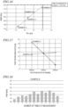
- FIG. 11 is a graph showing results of an investigation on the relationship between the grit size of the whetstone and the crushing ratio of the primary-crystal silicon grains.
- the first honing process was performed with a #600 diamond whetstone, and then the second honing process was performed with a diamond whetstone having a predetermined grit size so as to obtain a polishing depth of 4 ⁇ m.
- the crushing ratio of the primary-crystal silicon grains was measured.
- the horizontal axis represents the grit size of the whetstone used in the second honing process
- the vertical axis represents the crushing ratio of the primary-crystal silicon grains. It is seen from FIG. 11 that in the case where the grit size of the whetstone is #3000 or of a larger number, the crushing ratio of the primary-crystal silicon grains may be decreased to 200 or lower.
- Example 1 a sample of the engine 100 according to an embodiment of the present invention was produced (example 1), and the effect of decreasing the consumption amount of oil thereof was compared with that of an engine in comparative example 1. The results of the investigation will be described.
- the cylinder block 10 of the engine 100 in example 1 was produced by the method described above.
- two honing processes were performed. Specifically, a rough honing process was performed for the purpose of forming oil grooves, and a finish honing process was performed for the purpose of forming a plateau portion between the oil grooves.
- FIG. 12 shows a roughness curve of a sliding surface in comparative example 1
- FIG. 13 shows a roughness curve of the sliding surface 12a in example 1. From a comparison between FIG. 12 and FIG. 13 , it is seen that the surface roughness of the sliding surface 12a in example 1 is smaller than the surface roughness of the sliding surface in comparative example 1.
- the ten-point average surface roughness Rz JIS of the sliding surface in comparative example 1 was 3.05 ⁇ m
- the ten-point average surface roughness Rz JIS of the sliding surface 12a in example 1 was 0.25 ⁇ m.
- the crushing ratio of the primary-crystal silicon grains 2 at the sliding surface 12a in example 1 was 200 or lower.
- FIG. 14 shows the consumption amount of oil measured by an extraction method in each of comparative example 1 and example 1. As can be seen from FIG. 14 , the consumption amount of the oil was smaller by 21% in example 1 than in comparative example 1.
- FIG. 15A is a schematic view showing how oil OL is scraped off by a piston ring 42 at a sliding surface 12a' of a cylinder wall 12' included in the engine in comparative example 1.
- the surface roughness (ten-point average surface roughness Rz JIS ) of the sliding surface 12a' is relatively large, and therefore, the oil OL remains in a large amount in the sliding surface 12a' without being scraped off by the piston ring 42.
- the remaining oil OL is exposed to flame FL to evaporate or combust. Therefore, in the case where the amount of the remaining oil OL is large, the consumption amount of the oil is large.
- FIG. 15B is a schematic view showing how oil OL is scraped off by the piston ring 42 at the sliding surface 12a of the cylinder wall 12 included in the engine 100 in example 1.
- the ten-point average surface roughness Rz JIS of the sliding surface 12a is as small as 0.25 ⁇ m. It is considered that this decreases the amount of the oil OL remaining in the sliding surface 12 and thus decreases the consumption amount of the oil.
- FIG. 16 are each an average value of the FMEPs at rotation rates of the engine of 4400 rpm, 4800 rpm and 5200 rpm.
- FIG. 16 also shows an FMEP of the engine in comparative example 1 (120.1 kPa) with the one-dot chain line.
- FIG. 17 shows FMEP decreasing ratios in each of examples 2 and 3 at rotation rates of the engine of 4400 rpm, 4800 rpm and 5200 rpm. It is seen from FIG. 17 that the effect of decreasing the FMEP tends to be greater on the lower side of the rotation rate.
- FIG. 18 shows results of measurement of the FMEP performed in repetition in example 6.
- the ten-point average surface roughness Rz JIS of the sliding surface was 0.563 ⁇ m (after being measured nine times) .
- FIG. 19 shows results of measurement of the FMEP performed in repetition in comparative example 2.
- the FMEPs were lower by 10% or greater in example 6 than in comparative example 2 at all the timings.
- the FMEP was lower by 17% in example 6 than in comparative example 2.
- example 6 exhibited an effect of decreasing the FMEP by 10% or greater (specifically 10.3%) .
- a vibration friction wear test (SRV test) was performed on a barrel-type test piece mimicking the piston skirt and on a cylinder test piece cut from the cylinder wall.
- the SRV test was performed for example 7, in which the ten-point average surface roughness Rz JIS of the sliding surface 12a was 0.124 to 0.237 ⁇ m (0.162 ⁇ m on average) and the crushing ratio of the primary-crystal silicon grains 2 was 150, and also for comparative example 3, in which the ten-point average surface roughness Rz JIS of the sliding surface was 1.6 to 3.2 ⁇ m.
- the SRV test was performed with the barrel-type test piece being slid at a constant load in a temperature of oil of 130°C (immersed in the oil), and the heights of wear of the barrel-type test piece and the cylinder test piece were measured.
- FIG. 20 shows changes in the height of wear of the barrel-type test piece along time. It is seen from FIG. 20 that the height of wear of the barrel-type test piece is lower in example 7 than in comparative example 3. At 60 minutes after the start of the test, the height of wear was lower by 69% in example 7 than in comparative example 3. As can be seen, it has been confirmed that the aggressiveness of the cylinder wall 12 to the other members is decreased in example 7.
- FIG. 21 shows changes in the height of wear of the cylinder test piece along time. It is seen from FIG. 21 that the height of wear of the cylinder test piece is lower in example 7 than in comparative example 3. As can be seen, it has been confirmed that the wear resistance of the cylinder wall 12 is improved in example 7.
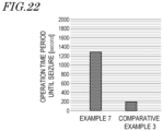
- example 7 and comparative example 3 the engine was operated under the conditions promoting seizure of the cylinder and the piston, and the time period from the start of the operation until the seizure occurred was measured.
- FIG. 22 shows results of measurement of the time period from the start of the operation until the seizure occurred.
- the time period until the seizure occurred was about 6.5 times longer in example 7 than in comparative example 3. It has been confirmed that the seizure resistance of the cylinder wall 12 is improved in example 7.
- the engine 100 according to an embodiment of the present invention is preferably usable for various types of transportation vehicles.
- FIG. 23 shows an example of automatic two-wheeled vehicle including the engine 100 according to an embodiment of the present invention.
- a head pipe 302 is provided at a front end of a main body frame 301.
- a front fork 303 is attached to the head pipe 302 so as to be swingable in a left-right direction of the vehicle.
- a front wheel 304 is rotatably supported at a bottom end of the front fork 303.
- a seat rail 306 is attached so as to extend rearward from a top portion of a rear end of the main body frame 301.
- a fuel tank 307 is provided on the main body frame 301, and a main seat 308a and a tandem seat 308b are provided on the seat rail 306.
- a rear arm 309 extending rearward is attached to the rear end of the main body frame 301.
- a rear wheel 310 is rotatably supported at a rear end of the rear arm 309.
- the engine 100 is held on a central portion of the main body frame 301.
- a radiator 311 is provided to the front of the engine 100.
- An exhaust pipe 312 is connected to an exhaust port of the engine 100, and a muffler 313 is attached to a rear end of the exhaust pipe 312.
- a transmission 315 is coupled with the engine 100.
- a drive sprocket 317 is attached to an output shaft 316 of the transmission 315.
- the drive sprocket 317 is coupled with a rear wheel sprocket 319 of the rear wheel 310 via a chain 318.
- the transmission 315 and the chain 318 act as a transmission mechanism that transmits power generated by the engine 100 to the driving wheel.
- the automatic two-wheeled vehicle 300 includes the engine 100 according to an embodiment of the present invention, and therefore, obtains effects of, for example, improving the fuel efficiency, decreasing the consumption amount of oil, and suppressing deterioration in performance of a catalyst.
- the automatic two-wheeled vehicle is shown as an example of the transportation vehicle.
- the engine according to an embodiment of the present invention is not limited to being used for an automatic two-wheeled vehicle, and is also preferably usable for any other transportation vehicle such as an automatic four-wheeled vehicle, an automatic three-wheeled vehicle, a seacraft or the like.
- the internal combustion engine 100 includes the piston 40 formed of an aluminum alloy; and the cylinder block 10 including the cylinder wall 12 including the sliding surface 12a, along which the piston 40 is slidable.
- the cylinder block 10 is formed of an aluminum alloy containing silicon, and includes the plurality of primary-crystal silicon grains 2 at the sliding surface 12a.
- the sliding surface 12a has a ten-point average surface roughness Rz JIS of 0.5 ⁇ m or smaller, and the plurality of primary-crystal silicon grains 2 at the sliding surface 12a have a crushing ratio of 200 or lower.
- the ten-point average surface roughness Rz JIS of the sliding surface 12a of the cylinder wall 12 is 0.5 ⁇ m or smaller.
- the sliding surface 12a has the projected and recessed portions that are sufficiently small to cause the sliding surface 12a to be considered as being mirror-finished. Therefore, a uniform oil film is formed at the sliding surface 12a, which may decrease the friction resistance. This may decrease the sliding loss and improve the fuel efficiency.
- the oil (lubricant oil) remaining in the surface of the cylinder wall 12 is decreased in the amount as a result of being scraped off by the piston ring 42. This decreases the consumption amount of the oil and suppresses deterioration in performance of a catalyst.
- the small size of the projected and recessed portions at the sliding surface 12a decreases the aggressiveness of the cylinder wall 12 to the other members (aggressiveness to the piston rings 42 and the piston skirt 44) .
- the primary-crystal silicon grains 2, which are highly hard, are present at the sliding surface 12a. Therefore, the surface pressure applied to the alloy substrate (matrix) 1 is decreased, and thus a sufficient level of seizure resistance may be guaranteed.
- a groove such as a cross hatch is not necessary, and thus the oil may be prevented from escaping into the groove. Therefore, the oil film has a higher pressure and a fluid lubrication state is preferably realized. This also guarantees a certain level of seizure resistance.
- the crushing ratio of the primary-crystal silicon grains 2 at the sliding surface 12a of the cylinder wall 12 is 200 or lower. Therefore, a large number of the primary-crystal silicon grains 2 that are not crushed (that may be considered "healthy") are exposed at the sliding surface 12a. This also decreases the aggressiveness to the other members. In addition, the contact load with the piston skirt 44 and the piston rings 42 is dispersed in the exposed healthy primary-crystal silicon grains 2, which improves the seizure resistance and the wear resistance of the cylinder wall 12.
- the sliding surface 12a has an arithmetic average roughness Ra that is smaller than 0.05 ⁇ m.
- the projected and recessed portions at the sliding surface 12a are small. Therefore, a uniform oil film is formed at the sliding surface 12a, which may decrease the friction resistance. This may decrease the sliding loss and improve the fuel efficiency.
- the oil remaining in the surface of the cylinder wall 12 is decreased in the amount as a result of being scraped off by the piston ring 42. This decreases the consumption amount of the oil and suppresses deterioration in performance of a catalyst.
- the small size of the projected and recessed portions at the sliding surface 12a decreases the aggressiveness of the cylinder wall 12 to the other members (aggressiveness to the piston rings 42 and the piston skirt 44) .
- the plurality of primary-crystal silicon grains 2 have an area size occupying a ratio of 8% or higher of an area size of the sliding surface.
- the surface pressure applied to the alloy substrate 1 is decreased, which improves the seizure resistance and the wear resistance.
- the sliding surface 12a is divided into a plurality of grids Sq each having a size of 0.1 mm ⁇ 0.1 mm and the ratio of the number of grids Sq where no primary-crystal silicon grain 2 is present with respect to the total number of the grids Sq is referred to as a "blank ratio"
- the blank ratio is 55.5% or lower.
- the "blank ratio" is an index indicating how the primary-crystal silicon grains 2 are dispersed. A lower blank ratio indicates that the primary-crystal silicon grains 2 are better dispersed. In the case where the blank ratio of the sliding surface 12a is 55.5% or lower, the surface pressure applied to the alloy substrate 1 is sufficiently decreased. Therefore, the seizure resistance and the wear resistance are improved.
- the cylinder block 10 is formed of an aluminum alloy containing silicon at a content of 15% by mass or higher and 25% by mass or lower.
- the aluminum alloy as the material of the cylinder block 10 preferably contains silicon at a content of 15% by mass or higher and 25% by mass or lower.
- the silicon content is 15% by mass or higher, a sufficiently large amount of the primary-crystal silicon grains 2 may be deposited, which may sufficiently improve the wear resistance of the cylinder block 10.
- the strength of the cylinder block 10 may be kept sufficiently high.
- the plurality of primary-crystal silicon grains 2 have an average grain diameter of 8 ⁇ m or longer and 50 ⁇ m or shorter.
- the primary-crystal silicon grains 2 have an average grain diameter in the range of 8 ⁇ m or longer and 50 ⁇ m or shorter. In this case, the wear resistance of the cylinder block 10 may be further improved.
- the average grain diameter of the primary-crystal silicon grains 2 is longer than 50 ⁇ m, the number of the primary-crystal silicon grains 2 per unit area size of the sliding surface 12a is small. Therefore, a large load is applied to each of the primary-crystal silicon grains 2 while the engine 100 is operated, and the primary-crystal silicon grains 2 may possibly be crushed.
- the crushed pieces of the primary-crystal silicon grains 2 act undesirably as polishing particles, which causes a risk that the sliding surface 12a is significantly worn.
- the average grain diameter of the primary-crystal silicon grains 2 is shorter than 8 ⁇ m, merely a small part of the primary-crystal silicon grains 2 is embedded in the matrix 1. Therefore, the primary-crystal silicon grains 2 easily fall while the engine 100 is operated.
- the primary-crystal silicon grains 2 that have fallen act undesirably as polishing particles, which causes a risk that the sliding surface 12a is significantly worn.
- the primary-crystal silicon grains 2 are present in a sufficient number per unit area size of the sliding surface 12a. Therefore, the load applied to each of the primary-crystal silicon grains 2 while the engine 100 is operated is relatively small, which suppresses the crushing of the primary-crystal silicon grains 2. Since the part of the primary-crystal silicon grains 2 that is embedded in the matrix 1 is sufficiently large, the fall of the primary-crystal silicon grains 2 is suppressed. Therefore, the wear of the sliding surface 12a by the primary-crystal silicon grains 2 that have fallen is suppressed.
- the piston 40 includes the piston main body 41 and the plurality of piston rings 42 attached to the outer circumferential portion of the piston main body 42, and each of the plurality of piston rings 42 includes the diamond-like carbon layer DLC on the outer circumferential portion thereof.
- each of the plurality of piston rings 42 includes the diamond-like carbon layer DLC on the outer circumferential portion thereof, the cylinder wall 12 may be prevented with more certainty from being scuffed by the piston rings 42.
- the piston 40 includes the piston head 43 and the piston skirt 44 extending from the outer circumferential portion of the piston head 43, and the piston skirt 44 includes the resin layer rl or the plating layer formed on at least a part of the outer circumferential surface thereof.
- the wear resistance and the seizure resistance of the piston 40 may be improved.
- the transportation vehicle includes the internal combustion engine 100 having any of the above-described structures.
- the internal combustion engine 100 is preferably usable in any of various types of transportation vehicles.
- the friction resistance of a cylinder wall and the consumption amount of oil may be decreased while a certain level of seizure resistance is provided with certainty.
- the internal combustion engine according to an embodiment of the present invention is preferably usable in any of various types of transportation vehicles including an automatic two-wheeled vehicle.
- 1 matrix (alloy substrate); 2: primary-crystal silicon grain; 2a: crushed part of the primary-crystal silicon grain; 2b: non-crushed part of the primary-crystal silicon grain; 10: cylinder block; 11: cylinder bore; 12: cylinder wall; 12a: sliding surface (inner circumferential surface of the cylinder wall); 13: outer wall; 14: water jacket; 20: cylinder head; 21: intake port; 22: exhaust port; 23: intake valve; 24: exhaust valve; 30: crankcase; 40: piston; 41: piston main body; 42: piston ring; 42a: top ring; 42b: second ring; 42c: third ring; 42D: diamond-like carbon layer; 43: piston head; 44: piston skirt; 48: piston pin; 50: crankshaft; 51: crankpin; 52: crank arm; 60: con rod; 61: rod main body; 62: small end portion; 63: large end portion; 70: combustion chamber; 100: engine (internal combustion engine); 300: automatic two-wheeled
Landscapes
- Engineering & Computer Science (AREA)
- Chemical & Material Sciences (AREA)
- Combustion & Propulsion (AREA)
- Mechanical Engineering (AREA)
- General Engineering & Computer Science (AREA)
- Pistons, Piston Rings, And Cylinders (AREA)
Abstract
Description
- The present disclosure relates to an internal combustion engine, and specifically to an internal combustion engine including a cylinder block formed of an aluminum alloy containing silicon, and also relates to a transportation vehicle including such an internal combustion engine.
- Recently, for the purpose of reducing the weight of an internal combustion engine, an aluminum alloy has been used more and more widely to form cylinder blocks. Cylinder blocks are required to have a high wear resistance. Therefore, an aluminum alloy containing a high content of silicon, namely, an aluminum-silicon-based alloy having a hyper eutectic composition is considered promising as an aluminum alloy for cylinder blocks. In a cylinder block formed of an aluminum-silicon-based alloy, silicon crystal grains located at a sliding surface contribute to improvement in the wear resistance. Such a cylinder block formed of an aluminum-silicon-based alloy is disclosed in, for example, Patent Document No. 1.
- In order to improve the wear resistance or the seizure resistance of the cylinder block, a mesh-like groove referred to as a cross hatch is generally formed in a surface of a cylinder wall defining a cylinder bore. Oil (lubricant oil) is retained in the cross hatch, and thus a state where the cylinder wall and a piston skirt or a piston ring operate smoothly with respect to each other may be kept. This may suppress wear and seizure.
- Patent Document No. 1:
WO2004/002658 - However, projected and recessed portions caused at the surface of the cylinder wall during the formation of the cross hatch prevents an oil film to be formed uniformly. This partially ruptures the oil film and thus increases the friction resistance. In addition, the oil retained in the cross hatch remains in the surface of the cylinder wall without being scraped off, and is exposed to high temperature combustion gas to evaporate or combust and thus is discharged as exhaust gas. This increases the consumption amount of the oil, which progressively deteriorates performance of a catalyst.
- An embodiment of the present invention made in light of the above-described problems has an object of, in an internal combustion engine including a cylinder block formed of an aluminum alloy containing silicon, decreasing the friction resistance of a cylinder wall and the consumption amount of oil while providing a certain level of seizure resistance with certainty.
- This specification discloses the internal combustion engine and the transportation vehicle described in the following items.
[Item 1]
An internal combustion engine, including: - a piston formed of an aluminum alloy; and
- a cylinder block including a cylinder wall including a sliding surface, along which the piston is slidable;
- wherein the cylinder block is formed of an aluminum alloy containing silicon, and includes a plurality of primary-crystal silicon grains at the sliding surface;
- wherein the sliding surface has a ten-point average surface roughness RzJIS of 0.5 µm or smaller, and
- wherein the plurality of primary-crystal silicon grains at the sliding surface have a crushing ratio of 200 or lower.
- In the engine according to an embodiment of the present invention, the ten-point average surface roughness RzJIS of the sliding surface of the cylinder wall is 0.5 µm or smaller. Namely, the sliding surface has projected and recessed portions that are sufficiently small to cause the sliding surface to be considered as being mirror-finished. Therefore, a uniform oil film is formed at the sliding surface, which may decrease the friction resistance. This may decrease the sliding loss and improve the fuel efficiency. In addition, oil (lubricant oil) remaining in the surface of the cylinder wall is decreased in the amount as a result of being scraped off by a piston ring. This decreases the consumption amount of the oil and suppresses deterioration in performance of a catalyst. Furthermore, the small size of the projected and recessed portions at the sliding surface decreases aggressiveness of the cylinder wall to other members (aggressiveness to piston rings and a piston skirt).
- There is a concern that when the surface roughness of the sliding surface is decreased, the amount of the oil retained in the sliding surface may be decreased and thus the seizure resistance may be decreased. However, in the engine according to an embodiment of the present invention, the primary-crystal silicon grains, which are highly hard, are present at the sliding surface. Therefore, the surface pressure applied to an alloy substrate (matrix) is decreased, and thus a sufficient level of seizure resistance may be guaranteed. A groove such as a cross hatch is not necessary, and thus the oil may be prevented from escaping into the groove. Therefore, the oil film has a higher pressure and a fluid lubrication state is preferably realized. This also guarantees a certain level of seizure resistance.
- In the engine according to an embodiment of the present invention, the crushing ratio of the primary-crystal silicon grains at the sliding surface of the cylinder wall is 200 or lower. Therefore, a large number of the primary-crystal silicon grains that are not crushed (that may be considered "healthy") are exposed at the sliding surface. This also decreases the aggressiveness to the other members. In addition, the contact load with the piston skirt and the piston rings is dispersed in the exposed healthy primary-crystal silicon grains, which improves the seizure resistance and the wear resistance of the cylinder wall.
- The internal combustion engine of
item 1, wherein the sliding surface has an arithmetic average roughness Ra that is smaller than 0.05 µm. - In the case where the arithmetic average roughness Ra of the sliding surface of the cylinder wall is smaller than 0.05 µm, the projected and recessed portions at the sliding surface are small. Therefore, a uniform oil film is formed at the sliding surface, which may decrease the friction resistance. This may decrease the sliding loss and improve the fuel efficiency. In addition, the oil remaining in the surface of the cylinder wall is decreased in the amount as a result of being scraped off by the piston ring. This decreases the consumption amount of the oil and suppresses deterioration in performance of a catalyst. Furthermore, the small size of the projected and recessed portions at the sliding surface decreases the aggressiveness of the cylinder wall to the other members (aggressiveness to the piston rings and the piston skirt).
- The internal combustion engine of
item - In the case where the ratio of the area size occupied by the primary-crystal silicon grains with respect to the area size of the sliding surface is 8% or higher, the surface pressure applied to the alloy substrate is decreased, which improves the seizure resistance and the wear resistance.
- The internal combustion engine of any one of
items 1 through 3, wherein where the sliding surface is divided into a plurality of grids each having a size of 0.1 mm × 0.1 mm and the ratio of the number of grids where no primary-crystal silicon grain is present with respect to the total number of the grids is referred to as a "blank ratio", the blank ratio is 55.5% or lower. - The "blank ratio" is an index indicating how the primary-crystal silicon grains are dispersed. A lower blank ratio indicates that the primary-crystal silicon grains are better dispersed. In the case where the blank ratio of the sliding surface is 55.5% or lower, the surface pressure applied to the alloy substrate is sufficiently decreased. Therefore, the seizure resistance and the wear resistance are improved.
- The internal combustion engine of any one of
items 1 through 4, wherein the cylinder block is formed of an aluminum alloy containing silicon at a content of 15% by mass or higher and 25% by mass or lower. - From the point of view of sufficiently improving the wear resistance and the strength of the cylinder block, the aluminum alloy as the material of the cylinder block preferably contains silicon at a content of 15% by mass or higher and 25% by mass or lower. In the case where the silicon content is 15% by mass or higher, a sufficiently large amount of the primary-crystal silicon grains may be deposited, which may sufficiently improve the wear resistance of the cylinder block. In the case where the silicon content is 25% by mass or lower, the strength of the cylinder block may be kept sufficiently high.
- The internal combustion engine of any one of
items 1 through 5, wherein the plurality of primary-crystal silicon grains have an average grain diameter of 8 µm or longer and 50 µm or shorter. - The primary-crystal silicon grains have an average grain diameter in the range of 8 µm or longer and 50 µm or shorter. In this case, the wear resistance of the cylinder block may be further improved.
- In the case where the average grain diameter of the primary-crystal silicon grains is longer than 50 µm, the number of the primary-crystal silicon grains per unit area size of the sliding surface is small. Therefore, a large load is applied to each of the primary-crystal silicon grains while the engine is operated, and the primary-crystal silicon grains may possibly be crushed. The crushed pieces of the primary-crystal silicon grains act undesirably as polishing particles, which causes a risk that the sliding surface is significantly worn.
- In the case where the average grain diameter of the primary-crystal silicon grains is shorter than 8 µm, merely a small part of the primary-crystal silicon grains is embedded in the matrix. Therefore, the primary-crystal silicon grains easily fall while the engine is operated. The primary-crystal silicon grains that have fallen act undesirably as polishing particles, which causes a risk that the sliding surface is significantly worn.
- By contrast, in the case where the average grain diameter of the primary-crystal silicon grains is 8 µm or longer and 50 µm or shorter, the primary-crystal silicon grains are present in a sufficient number per unit area size of the sliding surface. Therefore, the load applied to each of the primary-crystal silicon grains while the engine is operated is relatively small, which suppresses the crushing of the primary-crystal silicon grains. Since the part of the primary-crystal silicon grains that is embedded in the matrix is sufficiently large, the fall of the primary-crystal silicon grains is suppressed. Therefore, the wear of the sliding surface by the primary-crystal silicon grains that have fallen is suppressed.
- The internal combustion engine of any one of
items 1 through 6, - wherein the piston includes a piston main body and a plurality of piston rings attached to an outer circumferential portion of the piston main body, and
- wherein each of the plurality of piston rings includes a diamond-like carbon layer on an outer circumferential portion thereof.
- In the case where each of the plurality of piston rings includes the diamond-like carbon layer on the outer circumferential portion thereof, the cylinder wall may be prevented with more certainty from being scuffed by the piston rings.
- The internal combustion engine of any one of
items 1 through 7, - wherein the piston includes a piston head and a piston skirt extending from an outer circumferential portion of the piston head, and
- wherein the piston skirt includes a resin layer or a plating layer formed on at least a part of an outer circumferential surface thereof.
- In the case where the piston skirt includes the resin layer or the plating layer formed on at least a part of the outer circumferential surface thereof, the wear resistance and the seizure resistance of the piston may be improved.
- A transportation vehicle, comprising the internal combustion engine of any one of
items 1 through 8. - The internal combustion engine according to an embodiment of the present invention is preferably usable in any of various types of transportation vehicles.
- According to an embodiment of the present invention, in an internal combustion engine including a cylinder block formed of an aluminum alloy containing silicon, the friction resistance of a cylinder wall and the consumption amount of oil may be decreased while a certain level of seizure resistance is provided with certainty.
-
-
FIG. 1 is a cross-sectional view schematically showing an engine (internal combustion engine) 100 according to an embodiment of the present invention. -
FIG. 2 is a side view schematically showing apiston 40 included in theengine 100. -
FIG. 3 is a perspective view schematically showing acylinder block 10 included in theengine 100. -
FIG. 4 is a cross-sectional view schematically showing a slidingsurface 12a of acylinder wall 12 and the vicinity thereof. -
FIG. 5 shows an example of image of the slidingsurface 12a. -
FIG. 6 is a view provided to illustrate the definition of a blank ratio of the slidingsurface 12a. -
FIG. 7 is a cross-sectional view schematically showing apiston ring 42 of thepiston 40. -
FIG. 8 is a cross-sectional view schematically showing apiston skirt 44 of thepiston 40. -
FIG. 9 is a flowchart showing production steps of thecylinder block 10. -
FIG. 10 is a flowchart showing production steps of thecylinder block 10. -
FIG. 11 is a graph showing the relationship between the grit size of the whetstone and the crushing ratio of the primary-crystal silicon grains. -
FIG. 12 is a graph showing a roughness curve of a sliding surface in comparative example 1. -
FIG. 13 is a graph showing a roughness curve of the slidingsurface 12a in example 1. -
FIG. 14 is a graph showing the consumption amount of oil measured by an extraction method in each of comparative example 1 and example 1. -
FIG. 15A is a schematic view showing how oil OL is scraped off by apiston ring 42 at a slidingsurface 12a' of a cylinder wall 12' included in an engine in comparative example 1. -
FIG. 15B is a schematic view showing how oil OL is scraped off by thepiston ring 42 at the slidingsurface 12a of thecylinder wall 12 included in the engine in example 1. -
FIG. 16 is a graph showing results of measurement of the friction mean effective pressure (FMEP) in each of examples 2 through 5. -
FIG. 17 is a graph showing FMEP decreasing ratios in each of examples 2 and 3 at rotation rates of the engine of 4400 rpm, 4800 rpm and 5200 rpm. -
FIG. 18 is a graph showing results of measurement of the FMEP performed in repetition in example 6. -
FIG. 19 is a graph showing results of measurement of the FMEP performed in repetition in comparative example 2. -
FIG. 20 is a graph showing a change in the height of wear of a barrel-type test piece along time in an SRV test performed in each of example 7 and comparative example 3. -
FIG. 21 is a graph showing a change in the height of wear of a cylinder test piece along time in an SRV test performed in each of example 7 and comparative example 3. -
FIG. 22 is a graph showing the time period from the start of operation of the engine until seizure of the piston and the cylinder occurs in each of example 7 and comparative example 3. -
FIG. 23 is a side view schematically showing an automatic two-wheeled vehicle 300 including theengine 100. - Hereinafter, an embodiment of the present invention will be described with reference to the drawings. While a water-cooled engine will be described as an example below, the engine according to an embodiment of the present invention is not limited to being of a water-cooled type and may be of an air-cooled type. While a single-cylinder engine will be described as an example below, there is no specific limitation on the number of the cylinders in the engine.
-
FIG. 1 shows an engine (internal combustion engine) 100 according to an embodiment of the present invention.FIG. 1 is a cross-sectional view schematically showing theengine 100. - As shown in
FIG. 1 , theengine 100 includes acylinder block 10, acylinder head 20, and acrankcase 30. Theengine 100 further includes apiston 40, acrankshaft 50, and a con rod (connecting rod) 60. The following description will be made with settings that a direction from thecylinder block 10 toward thecylinder head 20 is an "upward direction" and a direction from thecylinder block 10 toward thecrankcase 30 is a "downward direction". - The cylinder block (may also be referred to as a "cylinder body") 10 includes a
cylinder wall 12 and anouter wall 13. Thecylinder wall 12 is formed to define acylinder bore 11. Theouter wall 13 surrounds thecylinder wall 12 and forms an outer enclosure of thecylinder block 10. Awater jacket 14 holding cooling water is provided between thecylinder wall 12 and theouter wall 13. - The
cylinder head 20 is provided above thecylinder block 10. Thecylinder head 20 defines acombustion chamber 70 together with thecylinder wall 12 and thepiston 40. Thecylinder head 20 includes anintake port 21, through which fuel is to be introduced into thecombustion chamber 70, and an exhaust port 22, through which exhaust gas is to be discharged from thecombustion chamber 70. Anintake valve 23 is provided in theintake port 21, and anexhaust valve 24 is provided in the exhaust port 22. - The
crankcase 30 is provided below thecylinder block 10. Namely, thecrankcase 30 is located so as to be on the side opposite to thecylinder head 20 with thecylinder block 10 being located therebetween. Thecrankcase 30 may be separate from, or may be integrally formed with, thecylinder block 10. - The
piston 40 is accommodated in the cylinder bore 11. In this embodiment, no cylinder sleeve is fit into the cylinder bore 11. Therefore, thepiston 40 moves up and down in a reciprocating manner in the cylinder bore 11 while being in contact with an inner circumferential surface (cylinder bore 11-side surface) 12a of thecylinder wall 12. Namely, the innercircumferential surface 12a of thecylinder wall 12 is a sliding surface along which thepiston 40 is slidable. - The
crankshaft 50 is accommodated in thecrankcase 30. Thecrankshaft 50 includes acrankpin 51 and acrank arm 52. - The
con rod 60 includes a rodmain body 61 having a rod-like shape, asmall end portion 62 provided at one end of the rodmain body 61, and alarge end portion 63 provided at the other end of the rodmain body 61. Thecon rod 60 connects thepiston 40 and thecrankshaft 50 to each other. Specifically, apiston pin 48 of thepiston 40 is inserted into a through-hole (piston pin hole) of thesmall end portion 62, and thecrankpin 51 of thecrankshaft 50 is inserted into a through-hole (crankpin hole) of thelarge end portion 63. This structure connects thepiston 40 and thecrankshaft 50 to each other. Abearing 66 is provided between an inner circumferential surface of thelarge end portion 63 and thecrankpin 51. -
FIG. 2 is a side view schematically showing thepiston 40 of theengine 100. In this embodiment, the piston 40 (more specifically, a pistonmain body 41 described below) is formed of an aluminum alloy. Thepiston 40 may be formed by forging or casting. As shown inFIG. 2 , thepiston 40 includes the pistonmain body 41 and a plurality of piston rings 42. The pistonmain body 41 includes apiston head 43 and apiston skirt 44. - The
piston head 43 is located at a top end of thepiston 40. Ring grooves holding the piston rings 42 are formed in an outer circumferential portion of thepiston head 43. Thepiston skirt 44 extends downward from the outer circumferential portion of thepiston head 43. - The piston rings 42 are attached to an outer circumferential portion of the piston
main body 41, more specifically, to the outer circumferential portion of thepiston head 43. In this embodiment, thepiston 40 includes threepiston rings 42. The number of the piston rings 42 is not limited to three. Among the threepiston rings 42, the piston rings at a top position and at a central position (a top ring and a second ring) 42a and 42b, for example, are compression rings that keep thecombustion chamber 70 in an airtight state. The piston ring at a bottom position (third ring) 42c is an oil ring that scrapes off extra oil attached to thecylinder wall 12. The piston rings 42 are formed of a metal material (e.g., steel). -
FIG. 3 is a perspective view schematically showing thecylinder block 10 of theengine 100. As described above, thecylinder block 10 includes thecylinder wall 12 including the slidingsurface 12a, and theouter wall 13. Thewater jacket 14 is provided between thecylinder wall 12 and theouter wall 13. In this embodiment, thecylinder block 10 is formed of an aluminum alloy containing silicon. More specifically, thecylinder block 10 is formed of an aluminum-silicon-based alloy having a hyper eutectic composition. -
FIG. 4 is a cross-sectional view schematically showing the slidingsurface 12a of thecylinder wall 12 and the vicinity thereof. As shown inFIG. 4 , thecylinder wall 12 of thecylinder block 10 includes an aluminum-containing solid-solution matrix (alloy substrate) 1 and a plurality of primary-crystal silicon grains 2 dispersed in thematrix 1. Some of the primary-crystal silicon grains 2 are exposed to the slidingsurface 12a. Namely, thecylinder block 10 includes the primary-crystal silicon grains 2 at the slidingsurface 12a. - Although not shown, the
cylinder wall 12 further includes a plurality of eutectic silicon grains dispersed in thematrix 1. Therefore, thecylinder block 10 may further include the eutectic silicon grains at the slidingsurface 12a. When a molten aluminum-silicon-based alloy having a hyper eutectic composition is cooled, relatively large silicon crystal grains are deposited first and then relatively small silicon crystal grains are deposited. The relatively large silicon crystal grains are the "primary-crystal silicon grains", and the relatively small silicon crystal grains are the "eutectic silicon grains". - In this embodiment, the
cylinder block 10 is formed such that the slidingsurface 12a has a ten-point average surface roughness RzJIS in a predetermined range. Specifically, the ten-point average surface roughness RzJIS of the slidingsurface 12a is 0.5 µm or smaller in generally the entirety of the slidingsurface 12a. - As represented by the following expression, the ten-point average surface roughness RzJIS is of a certain reference length of a profile curve, and is a difference between an average value of elevations of the highest peak through the fifth highest peak R1, R3, R5, R7 and R9, and an average value of elevations of the lowest trough through the fifth lowest trough R2, R4, R6, R8 and R10. The ten-point average surface roughness RzJIS may be measured by use of a surface roughness meter (e.g., Surfcom 1400D produced by Tokyo Seimitsu Co., Ltd.).

- In this embodiment, the
cylinder block 10 is formed such that the primary-crystal silicon grains 2 at the slidingsurface 12a are crushed at a crushing ratio in a predetermined range. Specifically, the crushing ratio of the primary-crystal silicon grains 2 at the slidingsurface 12a is 200 or lower in generally the entirety of the slidingsurface 12a. The crushing ratio of the primary-crystal silicon grains 2 is a ratio, represented by percentage, of the area size of the crushed part of the primary-crystal silicon grains 2 with respect to the area size of the primary-crystal silicon grains 2 at the slidingsurface 12a. A specific method for measuring the crushing ratio will be described below. - As described above, in the
engine 100 in this embodiment, the ten-point average surface roughness RzJIS of the slidingsurface 12a of thecylinder wall 12 is 0.5 µm or smaller. Namely, the slidingsurface 12a has projected and recessed portions that are sufficiently small to cause the slidingsurface 12a to be considered as being mirror-finished. Therefore, a uniform oil film is formed at the slidingsurface 12a, which may decrease the friction resistance. This may decrease the sliding loss and improve the fuel efficiency. In addition, oil (lubricant oil) remaining in the surface of thecylinder wall 12 is decreased in the amount as a result of being scraped off by thepiston ring 42. This decreases the consumption amount of the oil and suppresses deterioration in performance of a catalyst. Furthermore, the small size of the projected and recessed portions at the slidingsurface 12a decreases aggressiveness of thecylinder wall 12 to other members (aggressiveness to the piston rings 42 and the piston skirt 44). From the point of view of further enhancing the above-described effects, the ten-point average surface roughness RzJIS of the slidingsurface 12a is more preferably 0.3 µm or smaller. - There is a concern that when the surface roughness of the sliding
surface 12a is decreased, the amount of the oil retained in the slidingsurface 12a may be decreased and thus the seizure resistance may be decreased. However, in theengine 100 in this embodiment, the primary-crystal silicon grains 2, which are highly hard, are present at the slidingsurface 12a. Therefore, the surface pressure applied to the alloy substrate (matrix) 1 is decreased, and thus a sufficient level of seizure resistance may be guaranteed. A groove such as a cross hatch is not necessary, and thus the oil may be prevented from escaping into the groove. Therefore, the oil film has a higher pressure and a fluid lubrication state is preferably realized. This also guarantees a certain level of seizure resistance. - In the
engine 100 in this embodiment, the crushing ratio of the primary-crystal silicon grains 2 at the slidingsurface 12a of thecylinder wall 12 is 200 or lower. Therefore, a large number of the primary-crystal silicon grains 2 that are not crushed (that may be considered "healthy") are exposed at the slidingsurface 12a. This also decreases the aggressiveness to the other members. In addition, the contact load with thepiston skirt 44 and the piston rings 42 is dispersed in the exposed healthy primary-crystal silicon grains 2, which improves the seizure resistance and the wear resistance of thecylinder wall 12. - The crushing ratio of the primary-
crystal silicon grains 2 may be measured as follows, for example. - First, an image of the sliding
surface 12a is captured by use of a bore scope.FIG. 5 shows an example of the image of the slidingsurface 12a. As shown inFIG. 5 , crushedparts 2a of the primary-crystal silicon grains 2 andnon-crushed parts 2b of the primary-crystal silicon grains 2 are present at the slidingsurface 12a. Next, an area size S1 of the crushedparts 2a of the primary-crystal silicon grains 2 is found by binarization using image analysis software. The crushedparts 2a have a black external appearance, and thus may be distinguished by binarization from thenon-crushed parts 2b and thealloy substrate 1. Next, an area size S2 of the primary-crystal silicon grains 2 (including both of the crushedparts 2a and thenon-crushed parts 2b) is found by binarization using the image analysis software. Then, the crushing ratio of the primary-crystal silicon grains 2 is calculated based on the following expression from the found area sizes S1 and S2.
- The surface roughness of the sliding
surface 12a of thecylinder wall 12 may also be represented by, for example, an arithmetic average roughness Ra. In this embodiment, the slidingsurface 12a has an arithmetic average roughness Ra that is, for example, lower than 0.05 µm. - From the point of view of the seizure resistance and the wear resistance, the ratio of the area size occupied by the primary-
crystal silicon grains 2 with respect to the area size of the slidingsurface 12a is preferably 8% or higher. In the case where the ratio of the area size occupied by the primary-crystal silicon grains 2 with respect to the area size of the slidingsurface 12a is 8% or higher, the surface pressure applied to thealloy substrate 1 is decreased, which improves the seizure resistance and the wear resistance. - The ratio of the area size occupied by the primary-
crystal silicon grains 2 with respect to the area size of the slidingsurface 12a may be measured as follows, for example. First, an image of the slidingsurface 12a is captured by use of the bore scope. Next, the area size S2 of the primary-crystal silicon grains 2 is found by binarization using the image analysis software. Then, the ratio of the area size occupied by the primary-crystal silicon grains 2 may be calculated based on the following expression from the found area size S2 and an area size S3 of the entire viewing field for measurement.
- The sliding
surface 12a may also be evaluated by a "blank ratio".FIG. 6 is a view provided to illustrate the definition of the "blank ratio". As shown inFIG. 6 , the slidingsurface 12a is divided into a plurality of grids Sq each having a size of 0.1 mm × 0.1 mm. These grids Sq naturally include grids Sq1, where the primary-crystal silicon grains 2 are present, and grids Sq2, where the primary-crystal silicon grains 2 are not present. The "blank ratio" is the ratio (percentage) of the number of the grids Sq2 with no primary-crystal silicon grains 2 with respect to the total number of the grids Sq. - The "blank ratio" may be considered as an index indicating how the primary-
crystal silicon grains 2 are dispersed. A lower blank ratio indicates that the primary-crystal silicon grains 2 are better dispersed. In the case where the blank ratio of the slidingsurface 12a is 55.5% or lower, the surface pressure applied to thealloy substrate 1 is sufficiently decreased. Therefore, the seizure resistance and the wear resistance are improved. - From the point of view of sufficiently improving the wear resistance and the strength of the
cylinder block 10, the aluminum alloy as the material of thecylinder block 10 preferably contains silicon at a content of 15% by mass or higher and 25% by mass or lower. In the case where the silicon content is 15% by mass or higher, a sufficiently large amount of the primary-crystal silicon grains 2 may be deposited, which may sufficiently improve the wear resistance of thecylinder block 10. In the case where the silicon content is 25% by mass or lower, the strength of thecylinder block 10 may be kept sufficiently high. - The primary-
crystal silicon grains 2 have an average grain diameter in the range of 8 µm or longer and 50 µm or shorter. In this case, the wear resistance of thecylinder block 10 may be further improved. In the case where the average grain diameter of the primary-crystal silicon grains 2 is longer than 50 µm, the number of the primary-crystal silicon grains 2 per unit area size of the slidingsurface 12a is small. Therefore, a large load is applied to each of the primary-crystal silicon grains 2 while theengine 100 is operated, and the primary-crystal silicon grains 2 may possibly be crushed. The crushed pieces of the primary-crystal silicon grains 2 act undesirably as polishing particles, which causes a risk that the slidingsurface 12a is significantly worn. In the case where the average grain diameter of the primary-crystal silicon grains 2 is shorter than 8 µm, merely a small part of the primary-crystal silicon grains 2 is embedded in thematrix 1. Therefore, the primary-crystal silicon grains 2 easily fall while theengine 100 is operated. The primary-crystal silicon grains 2 that have fallen act undesirably as polishing particles, which causes a risk that the slidingsurface 12a is significantly worn. - By contrast, in the case where the average grain diameter of the primary-
crystal silicon grains 2 is 8 µm or longer and 50 µm or shorter (more preferably 12 µm or longer and 50 µm or shorter), the primary-crystal silicon grains 2 are present in a sufficient number per unit area size of the slidingsurface 12a. Therefore, the load applied to each of the primary-crystal silicon grains 2 while theengine 100 is operated is relatively small, which suppresses the crushing of the primary-crystal silicon grains 2. Since the part of the primary-crystal silicon grains 2 that is embedded in thematrix 1 is sufficiently large, the fall of the primary-crystal silicon grains 2 is suppressed. Therefore, the wear of the slidingsurface 12a by the primary-crystal silicon grains 2 that have fallen is suppressed. - The eutectic silicon grains have an average grain diameter shorter than that of the primary-
crystal silicon grains 2. The average grain diameter of the eutectic silicon grains is, for example, 7.5 µm or shorter. - The average grain diameters of the primary-
crystal silicon grains 2 and the eutectic silicon grains may be measured as follows by image processing performed on an image of the slidingsurface 12a. First, a diameter (equivalent diameter) of each of the silicon crystal grains with an assumption that the silicon crystal grains are of a true circle is calculated based on an area size of each silicon crystal grain obtained by the image processing. As a result, the number (frequency) and the diameters of the silicon crystal grains are specified. Tiny crystal grains each having a diameter shorter than 1 µm are not counted as silicon crystal grains. Based on the calculated number (frequency) and the calculated diameters of the silicon crystal grains, a grain size distribution of the silicon crystal grains is obtained. The obtained grain size distribution (histogram) includes two peaks. The grain size distribution is divided into two regions with the threshold being a diameter of a portion forming a trough between the two peaks. The region corresponding to longer diameters is set as the grain size distribution of the primary-crystal silicon grains, and the region corresponding to shorter diameters is set as the grain size distribution of the eutectic silicon grains. Based on each of the grain size distributions, the average crystal diameter of the primary-crystal silicon grains and the average crystal diameter of the eutectic silicon grains may be calculated. -
FIG. 7 is a cross-sectional view showing an example of structure of thepiston ring 42 of thepiston 40. In the example shown inFIG. 7 , a diamond-like carbon layer (hereinafter, referred to as a "DLC layer") 42D is formed on an outer circumferential portion (outer circumferential surface) of thepiston ring 42. The outer circumferential portion of thepiston ring 42 is a portion to be in contact with thecylinder wall 12. Thepiston ring 42 does not need to include theDLC layer 42D. However, theDLC layer 42D formed on the outer circumferential surface of each of the piston rings 42 may prevent, with more certainty, thecylinder wall 12 from being scuffed by the piston rings 42. - The
DLC layer 42D is preferably formed by a deposition method (e.g., a CVD method or a PVD method) . TheDLC layer 42D may have any composition or a thickness with no specific limitation. From the point of view of preventing the scuffing with more certainty, the thickness of theDLC layer 42D is preferably 2 µm or greater. From the point of view of the adhesiveness, the thickness of theDLC layer 42D is preferably 20 µm or less. -
FIG. 8 is a cross-sectional view showing an example of structure of thepiston skirt 44. In the example shown inFIG. 8 , thepiston skirt 44 includes a resin layer rl formed on at least a part of an outer circumferential surface thereof. The resin layer rl is provided on a substrate bl formed of an aluminum alloy. - The resin layer rl includes, for example, a polymer matrix and solid lubricant particles dispersed in the polymer matrix. As a material of the polymer matrix, thermosetting polyamideimide, for example, is preferably usable. Needless to say, the material of the polymer matrix is not limited to this. As the solid lubricant particles, any of various known types of solid lubricant particles may be used. For example, graphite particles and molybdenum disulfide particles are preferably usable. The resin layer rl may be formed by, for example, applying a liquid resin material to the
piston skirt 44 by a spray method or any of various printing methods (a screen printing method, a pad printing method or the like). - In the case where the
piston skirt 44 includes the resin layer rl formed on at least a part of the outer circumferential surface thereof, the wear resistance and the seizure resistance of thepiston 40 may be improved. - The
piston skirt 44 may include a plating layer (e.g., iron-plating layer) instead of the resin layer rl. Also in the case where thepiston skirt 44 includes the plating layer formed on at least a part of the outer circumferential surface thereof, the wear resistance and the seizure resistance of thepiston 40 may be improved. Thepiston skirt 44 may not need to include either the resin layer rl or the plating layer. - With reference to
FIG. 9 and FIG. 10 , a method for producing thecylinder block 10 included in theengine 100 according to this embodiment will be described.FIG. 9 and FIG. 10 are flowcharts showing production steps of thecylinder block 10. - First, a molded body formed of an aluminum alloy containing silicon is prepared (step ST1). This molded body includes primary-crystal silicon grains and eutectic silicon grains at, and in the vicinity of, a surface thereof. The step ST1 of preparing the molded body includes, for example, steps ST1a through ST1e shown in
FIG. 10 . - First, an aluminum alloy containing silicon is prepared (step ST1a). For the reasons described above, the content of silicon in the aluminum alloy is preferably 15% by mass or higher and 25% by mass or lower. The aluminum alloy contains aluminum at a content of, for example, 73.4% by mass or higher and 79.6% by mass or lower. The aluminum alloy may contain copper. In this case, the aluminum alloy contains copper at a content of, for example, 2.0% by mass or higher and 5.0% by mass or lower.
- Next, the prepared aluminum alloy is heated in a melting furnace to be melted and thus a molten aluminum alloy is formed (step ST1b). About 100 ppm by mass of phosphorus may be incorporated into the pre-melting aluminum alloy or the molten aluminum alloy. In the case where the aluminum alloy contains phosphorus at a content of 50 ppm by mass or higher and 200 ppm by mass or lower, increase in the size of the silicon crystal grains may be suppressed. Therefore, the silicon crystal grains may be dispersed uniformly in the alloy. The aluminum alloy may contain calcium at a content of 0.01% by mass or lower. In this manner, the effect provided by phosphorus that the size of the silicon crystal grains is decreased to an extremely minute level is guaranteed, and thus a metal tissue having a high wear resistance may be provided. Namely, it is preferred that the aluminum alloy contains phosphorus at a content of 50 ppm by mass or higher and 200 ppm by mass or lower and calcium at a content of 0.01% by mass or lower.
- Next, the molten aluminum alloy is used to perform casting (specifically, high-pressure dis-casting) (step ST1c). Namely, the molten aluminum alloy is cooled in a casting mold to form a molded body. In this step, a portion to be the sliding
surface 12a of thecylinder wall 12 is cooled at a high cooling rate (e.g., 4°C/second or higher and 50°C/second or lower). In this manner, a molded body including the silicon crystal grains, contributing to the wear resistance, at, and in the vicinity of, a surface thereof is obtained. The casting step ST1c may be performed by use of a casting device disclosed in, for example,WO2004/002658 . - Next, the molded body removed from the casting mold is subjected to one of heat treatments referred to as "T5", "T6" and "T7" (step ST1d). According to the T5 treatment, the molded body is, immediately after being removed from the casting mold, for example, washed with water or the like to be quenched, then is subjected to artificial aging at a predetermined temperature for a predetermined time period in order to improve the mechanical properties thereof and to stabilize the size thereof, and then is cooled with air. According to the T6 treatment, the molded body is, after being removed from the casting mold, subjected to a solution treatment at a predetermined temperature for a predetermined time period, then is cooled with water, then is subjected to artificial aging at a predetermined temperature for a predetermined time period, and then is cooled with air. According to the T7 treatment, the molded body is subjected to artificial aging more excessively than according to the T6 treatment. The T7 treatment may stabilize the size more than the T6 treatment, but results in a lower hardness than the T6 treatment.
- Next, the molded body is subjected to predetermined mechanical processing (step ST1e). Specifically, a surface of the molded body to be in contact with the
cylinder head 20 or thecrankcase 30 is, for example, shaved. - After the molded body is prepared as described above, an inner circumferential surface of a portion, of the molded body, to become the cylinder wall is subjected to a first honing process (referred to as a "rough honing process") (step ST2). Specifically, the inner circumferential surface is polished with a whetstone having a relatively small number of grit size (e.g., #600 diamond whetstone).
- Then, the inner circumferential surface is subjected to a second honing process (referred to as a "finish honing process") (step ST3). Specifically, the inner circumferential surface is polished with a whetstone having a larger number of grit size than used in the rough honing process (e.g., with a #3000 diamond whetstone). The rough honing process and the finish honing process may be performed by use of a honing device disclosed in, for example,
Japanese Laid-Open Patent Publication No. 2004-268179 - In this manner, the
cylinder block 10 may be obtained. The number of times of honing process is not limited to two as described above. The grit size of the whetstone to be used in the honing processes may be adjusted to control the ten-point average surface roughness RzJIS of the slidingsurface 12a. A whetstone having a relatively large number of grit size may be used in the final honing process among the plurality of honing processes, so that the ten-point average surface roughness RzJIS is decreased to 0.5 µm or smaller. It has been found out by the studies made by the present inventors that in the case where a whetstone having a grit size of #3000 or a larger number is used in the final honing process, the crushing ratio of the primary-crystal silicon grains 2 at the slidingsurface 12a may be decreased to 200 or lower. -
FIG. 11 is a graph showing results of an investigation on the relationship between the grit size of the whetstone and the crushing ratio of the primary-crystal silicon grains. For this investigation, the first honing process was performed with a #600 diamond whetstone, and then the second honing process was performed with a diamond whetstone having a predetermined grit size so as to obtain a polishing depth of 4 µm. After this, the crushing ratio of the primary-crystal silicon grains was measured. InFIG. 11 , the horizontal axis represents the grit size of the whetstone used in the second honing process, and the vertical axis represents the crushing ratio of the primary-crystal silicon grains. It is seen fromFIG. 11 that in the case where the grit size of the whetstone is #3000 or of a larger number, the crushing ratio of the primary-crystal silicon grains may be decreased to 200 or lower. - First, a sample of the
engine 100 according to an embodiment of the present invention was produced (example 1), and the effect of decreasing the consumption amount of oil thereof was compared with that of an engine in comparative example 1. The results of the investigation will be described. Thecylinder block 10 of theengine 100 in example 1 was produced by the method described above. For producing a cylinder block in comparative example 1, two honing processes were performed. Specifically, a rough honing process was performed for the purpose of forming oil grooves, and a finish honing process was performed for the purpose of forming a plateau portion between the oil grooves. -
FIG. 12 shows a roughness curve of a sliding surface in comparative example 1, andFIG. 13 shows a roughness curve of the slidingsurface 12a in example 1. From a comparison betweenFIG. 12 and FIG. 13 , it is seen that the surface roughness of the slidingsurface 12a in example 1 is smaller than the surface roughness of the sliding surface in comparative example 1. The ten-point average surface roughness RzJIS of the sliding surface in comparative example 1 was 3.05 µm, whereas the ten-point average surface roughness RzJIS of the slidingsurface 12a in example 1 was 0.25 µm. The crushing ratio of the primary-crystal silicon grains 2 at the slidingsurface 12a in example 1 was 200 or lower. -
FIG. 14 shows the consumption amount of oil measured by an extraction method in each of comparative example 1 and example 1. As can be seen fromFIG. 14 , the consumption amount of the oil was smaller by 21% in example 1 than in comparative example 1. -
FIG. 15A is a schematic view showing how oil OL is scraped off by apiston ring 42 at a slidingsurface 12a' of a cylinder wall 12' included in the engine in comparative example 1. In comparative example 1, the surface roughness (ten-point average surface roughness RzJIS) of the slidingsurface 12a' is relatively large, and therefore, the oil OL remains in a large amount in the slidingsurface 12a' without being scraped off by thepiston ring 42. The remaining oil OL is exposed to flame FL to evaporate or combust. Therefore, in the case where the amount of the remaining oil OL is large, the consumption amount of the oil is large. -
FIG. 15B is a schematic view showing how oil OL is scraped off by thepiston ring 42 at the slidingsurface 12a of thecylinder wall 12 included in theengine 100 in example 1. In example 1, the ten-point average surface roughness RzJIS of the slidingsurface 12a is as small as 0.25 µm. It is considered that this decreases the amount of the oil OL remaining in the slidingsurface 12 and thus decreases the consumption amount of the oil. - Now, results of an investigation on the effect of decreasing the friction resistance (friction loss) will be described. Regarding examples 2, 3, 4 and 5, in which the ten-point average surface roughness RzJIS of the sliding
surface 12a was respectively 0.224 µm, 0.334 µm, 0.403 µm and 0.496 µm, the friction mean effective pressure (FMEP) was measured by a floating liner method. In all of examples 2, 3, 4 and 5, the crushing ratio of the primary-crystal silicon grains 2 was 6 to 70. The FMEP is a value obtained by dividing the friction work per cycle by the piston stroke volume, and a higher FMEP indicates a larger friction force.FIG. 16 shows results of measurement of the FMEP. The FMEPs shownFIG. 16 are each an average value of the FMEPs at rotation rates of the engine of 4400 rpm, 4800 rpm and 5200 rpm.FIG. 16 also shows an FMEP of the engine in comparative example 1 (120.1 kPa) with the one-dot chain line. - It is seen from
FIG. 16 that as the ten-point average surface roughness RzJIS is smaller, the FMEP is lower, and that in the case where the ten-point average surface roughness RzJIS is 0.5 µm or lower as in examples 2 through 5, an FMEP lower than the FMEP in comparative example 1 is obtained. -
FIG. 17 shows FMEP decreasing ratios in each of examples 2 and 3 at rotation rates of the engine of 4400 rpm, 4800 rpm and 5200 rpm. It is seen fromFIG. 17 that the effect of decreasing the FMEP tends to be greater on the lower side of the rotation rate. - Now, results of an investigation on the continuity of the effect of decreasing the friction loss will be described. In example 6, the ten-point average surface roughness RzJIS of the sliding
surface 12a was 0.214 µm, and the crushing ratio of the primary-crystal silicon grains 2 was 200 or lower.FIG. 18 shows results of measurement of the FMEP performed in repetition in example 6. In comparative example 2, the ten-point average surface roughness RzJIS of the sliding surface was 0.563 µm (after being measured nine times) .FIG. 19 shows results of measurement of the FMEP performed in repetition in comparative example 2. - As can be seen from
FIG. 18 andFIG. 19 , when the measurement was performed for comparison at the same timings (with the same number of times of measurement), the FMEPs were lower by 10% or greater in example 6 than in comparative example 2 at all the timings. For example, at the first measurement, the FMEP was lower by 17% in example 6 than in comparative example 2. Even at the tenth measurement, in which the effect of decreasing the FMEP was minimum, example 6 exhibited an effect of decreasing the FMEP by 10% or greater (specifically 10.3%) . - Now, results of an investigation on the aggressiveness of the cylinder wall to the other members and on the wear resistance of the cylinder wall will be described. For this investigation, a vibration friction wear test (SRV test) was performed on a barrel-type test piece mimicking the piston skirt and on a cylinder test piece cut from the cylinder wall. The SRV test was performed for example 7, in which the ten-point average surface roughness RzJIS of the sliding
surface 12a was 0.124 to 0.237 µm (0.162 µm on average) and the crushing ratio of the primary-crystal silicon grains 2 was 150, and also for comparative example 3, in which the ten-point average surface roughness RzJIS of the sliding surface was 1.6 to 3.2 µm. The SRV test was performed with the barrel-type test piece being slid at a constant load in a temperature of oil of 130°C (immersed in the oil), and the heights of wear of the barrel-type test piece and the cylinder test piece were measured. -
FIG. 20 shows changes in the height of wear of the barrel-type test piece along time. It is seen fromFIG. 20 that the height of wear of the barrel-type test piece is lower in example 7 than in comparative example 3. At 60 minutes after the start of the test, the height of wear was lower by 69% in example 7 than in comparative example 3. As can be seen, it has been confirmed that the aggressiveness of thecylinder wall 12 to the other members is decreased in example 7. -
FIG. 21 shows changes in the height of wear of the cylinder test piece along time. It is seen fromFIG. 21 that the height of wear of the cylinder test piece is lower in example 7 than in comparative example 3. As can be seen, it has been confirmed that the wear resistance of thecylinder wall 12 is improved in example 7. - In example 7 and comparative example 3, the engine was operated under the conditions promoting seizure of the cylinder and the piston, and the time period from the start of the operation until the seizure occurred was measured.
FIG. 22 shows results of measurement of the time period from the start of the operation until the seizure occurred. - As shown in
FIG. 22 , the time period until the seizure occurred was about 6.5 times longer in example 7 than in comparative example 3. It has been confirmed that the seizure resistance of thecylinder wall 12 is improved in example 7. - The
engine 100 according to an embodiment of the present invention is preferably usable for various types of transportation vehicles.FIG. 23 shows an example of automatic two-wheeled vehicle including theengine 100 according to an embodiment of the present invention. - In an automatic two-
wheeled vehicle 300 shown inFIG. 23 , ahead pipe 302 is provided at a front end of amain body frame 301. Afront fork 303 is attached to thehead pipe 302 so as to be swingable in a left-right direction of the vehicle. Afront wheel 304 is rotatably supported at a bottom end of thefront fork 303. - A
seat rail 306 is attached so as to extend rearward from a top portion of a rear end of themain body frame 301. Afuel tank 307 is provided on themain body frame 301, and amain seat 308a and atandem seat 308b are provided on theseat rail 306. - A
rear arm 309 extending rearward is attached to the rear end of themain body frame 301. Arear wheel 310 is rotatably supported at a rear end of therear arm 309. - The
engine 100 is held on a central portion of themain body frame 301. Aradiator 311 is provided to the front of theengine 100. Anexhaust pipe 312 is connected to an exhaust port of theengine 100, and amuffler 313 is attached to a rear end of theexhaust pipe 312. - A
transmission 315 is coupled with theengine 100. Adrive sprocket 317 is attached to anoutput shaft 316 of thetransmission 315. Thedrive sprocket 317 is coupled with arear wheel sprocket 319 of therear wheel 310 via achain 318. Thetransmission 315 and thechain 318 act as a transmission mechanism that transmits power generated by theengine 100 to the driving wheel. - The automatic two-
wheeled vehicle 300 includes theengine 100 according to an embodiment of the present invention, and therefore, obtains effects of, for example, improving the fuel efficiency, decreasing the consumption amount of oil, and suppressing deterioration in performance of a catalyst. - In this embodiment, the automatic two-wheeled vehicle is shown as an example of the transportation vehicle. The engine according to an embodiment of the present invention is not limited to being used for an automatic two-wheeled vehicle, and is also preferably usable for any other transportation vehicle such as an automatic four-wheeled vehicle, an automatic three-wheeled vehicle, a seacraft or the like.
- As described above, the
internal combustion engine 100 according to an embodiment of the present invention includes thepiston 40 formed of an aluminum alloy; and thecylinder block 10 including thecylinder wall 12 including the slidingsurface 12a, along which thepiston 40 is slidable. Thecylinder block 10 is formed of an aluminum alloy containing silicon, and includes the plurality of primary-crystal silicon grains 2 at the slidingsurface 12a. The slidingsurface 12a has a ten-point average surface roughness RzJIS of 0.5 µm or smaller, and the plurality of primary-crystal silicon grains 2 at the slidingsurface 12a have a crushing ratio of 200 or lower. - In the
engine 100 according to an embodiment of the present invention, the ten-point average surface roughness RzJIS of the slidingsurface 12a of thecylinder wall 12 is 0.5 µm or smaller. Namely, the slidingsurface 12a has the projected and recessed portions that are sufficiently small to cause the slidingsurface 12a to be considered as being mirror-finished. Therefore, a uniform oil film is formed at the slidingsurface 12a, which may decrease the friction resistance. This may decrease the sliding loss and improve the fuel efficiency. In addition, the oil (lubricant oil) remaining in the surface of thecylinder wall 12 is decreased in the amount as a result of being scraped off by thepiston ring 42. This decreases the consumption amount of the oil and suppresses deterioration in performance of a catalyst. Furthermore, the small size of the projected and recessed portions at the slidingsurface 12a decreases the aggressiveness of thecylinder wall 12 to the other members (aggressiveness to the piston rings 42 and the piston skirt 44) . - There is a concern that when the surface roughness of the sliding
surface 12a is decreased, the amount of the oil retained in the slidingsurface 12a may be decreased and thus the seizure resistance may be decreased. However, in theengine 100 according to an embodiment of the present invention, the primary-crystal silicon grains 2, which are highly hard, are present at the slidingsurface 12a. Therefore, the surface pressure applied to the alloy substrate (matrix) 1 is decreased, and thus a sufficient level of seizure resistance may be guaranteed. A groove such as a cross hatch is not necessary, and thus the oil may be prevented from escaping into the groove. Therefore, the oil film has a higher pressure and a fluid lubrication state is preferably realized. This also guarantees a certain level of seizure resistance. - In the
engine 100 according to an embodiment of the present invention, the crushing ratio of the primary-crystal silicon grains 2 at the slidingsurface 12a of thecylinder wall 12 is 200 or lower. Therefore, a large number of the primary-crystal silicon grains 2 that are not crushed (that may be considered "healthy") are exposed at the slidingsurface 12a. This also decreases the aggressiveness to the other members. In addition, the contact load with thepiston skirt 44 and the piston rings 42 is dispersed in the exposed healthy primary-crystal silicon grains 2, which improves the seizure resistance and the wear resistance of thecylinder wall 12. - In an embodiment, the sliding
surface 12a has an arithmetic average roughness Ra that is smaller than 0.05 µm. - In the case where the arithmetic average roughness Ra of the sliding
surface 12a of thecylinder wall 12 is smaller than 0.05 µm, the projected and recessed portions at the slidingsurface 12a are small. Therefore, a uniform oil film is formed at the slidingsurface 12a, which may decrease the friction resistance. This may decrease the sliding loss and improve the fuel efficiency. In addition, the oil remaining in the surface of thecylinder wall 12 is decreased in the amount as a result of being scraped off by thepiston ring 42. This decreases the consumption amount of the oil and suppresses deterioration in performance of a catalyst. Furthermore, the small size of the projected and recessed portions at the slidingsurface 12a decreases the aggressiveness of thecylinder wall 12 to the other members (aggressiveness to the piston rings 42 and the piston skirt 44) . - In an embodiment, the plurality of primary-
crystal silicon grains 2 have an area size occupying a ratio of 8% or higher of an area size of the sliding surface. - In the case where the ratio of the area size occupied by the primary-
crystal silicon grains 2 with respect to the area size of the slidingsurface 12a is 8% or higher, the surface pressure applied to thealloy substrate 1 is decreased, which improves the seizure resistance and the wear resistance. - In an embodiment, where the sliding
surface 12a is divided into a plurality of grids Sq each having a size of 0.1 mm × 0.1 mm and the ratio of the number of grids Sq where no primary-crystal silicon grain 2 is present with respect to the total number of the grids Sq is referred to as a "blank ratio", the blank ratio is 55.5% or lower. - The "blank ratio" is an index indicating how the primary-
crystal silicon grains 2 are dispersed. A lower blank ratio indicates that the primary-crystal silicon grains 2 are better dispersed. In the case where the blank ratio of the slidingsurface 12a is 55.5% or lower, the surface pressure applied to thealloy substrate 1 is sufficiently decreased. Therefore, the seizure resistance and the wear resistance are improved. - In an embodiment, the
cylinder block 10 is formed of an aluminum alloy containing silicon at a content of 15% by mass or higher and 25% by mass or lower. - From the point of view of sufficiently improving the wear resistance and the strength of the
cylinder block 10, the aluminum alloy as the material of thecylinder block 10 preferably contains silicon at a content of 15% by mass or higher and 25% by mass or lower. In the case where the silicon content is 15% by mass or higher, a sufficiently large amount of the primary-crystal silicon grains 2 may be deposited, which may sufficiently improve the wear resistance of thecylinder block 10. In the case where the silicon content is 25% by mass or lower, the strength of thecylinder block 10 may be kept sufficiently high. - In an embodiment, the plurality of primary-
crystal silicon grains 2 have an average grain diameter of 8 µm or longer and 50 µm or shorter. - The primary-
crystal silicon grains 2 have an average grain diameter in the range of 8 µm or longer and 50 µm or shorter. In this case, the wear resistance of thecylinder block 10 may be further improved. - In the case where the average grain diameter of the primary-
crystal silicon grains 2 is longer than 50 µm, the number of the primary-crystal silicon grains 2 per unit area size of the slidingsurface 12a is small. Therefore, a large load is applied to each of the primary-crystal silicon grains 2 while theengine 100 is operated, and the primary-crystal silicon grains 2 may possibly be crushed. The crushed pieces of the primary-crystal silicon grains 2 act undesirably as polishing particles, which causes a risk that the slidingsurface 12a is significantly worn. - In the case where the average grain diameter of the primary-
crystal silicon grains 2 is shorter than 8 µm, merely a small part of the primary-crystal silicon grains 2 is embedded in thematrix 1. Therefore, the primary-crystal silicon grains 2 easily fall while theengine 100 is operated. The primary-crystal silicon grains 2 that have fallen act undesirably as polishing particles, which causes a risk that the slidingsurface 12a is significantly worn. - By contrast, in the case where the average grain diameter of the primary-
crystal silicon grains 2 is 8 µm or longer and 50 µm or shorter, the primary-crystal silicon grains 2 are present in a sufficient number per unit area size of the slidingsurface 12a. Therefore, the load applied to each of the primary-crystal silicon grains 2 while theengine 100 is operated is relatively small, which suppresses the crushing of the primary-crystal silicon grains 2. Since the part of the primary-crystal silicon grains 2 that is embedded in thematrix 1 is sufficiently large, the fall of the primary-crystal silicon grains 2 is suppressed. Therefore, the wear of the slidingsurface 12a by the primary-crystal silicon grains 2 that have fallen is suppressed. - In an embodiment, the
piston 40 includes the pistonmain body 41 and the plurality ofpiston rings 42 attached to the outer circumferential portion of the pistonmain body 42, and each of the plurality ofpiston rings 42 includes the diamond-like carbon layer DLC on the outer circumferential portion thereof. - In the case where each of the plurality of
piston rings 42 includes the diamond-like carbon layer DLC on the outer circumferential portion thereof, thecylinder wall 12 may be prevented with more certainty from being scuffed by the piston rings 42. - In an embodiment, the
piston 40 includes thepiston head 43 and thepiston skirt 44 extending from the outer circumferential portion of thepiston head 43, and thepiston skirt 44 includes the resin layer rl or the plating layer formed on at least a part of the outer circumferential surface thereof. - In the case where the
piston skirt 44 includes the resin layer rl or the plating layer formed on at least a part of the outer circumferential surface thereof, the wear resistance and the seizure resistance of thepiston 40 may be improved. - The transportation vehicle according to an embodiment of the present invention includes the
internal combustion engine 100 having any of the above-described structures. - The
internal combustion engine 100 according to an embodiment of the present invention is preferably usable in any of various types of transportation vehicles. - According to an embodiment of the present invention, in an internal combustion engine including a cylinder block formed of an aluminum alloy containing silicon, the friction resistance of a cylinder wall and the consumption amount of oil may be decreased while a certain level of seizure resistance is provided with certainty. The internal combustion engine according to an embodiment of the present invention is preferably usable in any of various types of transportation vehicles including an automatic two-wheeled vehicle.
- 1: matrix (alloy substrate); 2: primary-crystal silicon grain; 2a: crushed part of the primary-crystal silicon grain; 2b: non-crushed part of the primary-crystal silicon grain; 10: cylinder block; 11: cylinder bore; 12: cylinder wall; 12a: sliding surface (inner circumferential surface of the cylinder wall); 13: outer wall; 14: water jacket; 20: cylinder head; 21: intake port; 22: exhaust port; 23: intake valve; 24: exhaust valve; 30: crankcase; 40: piston; 41: piston main body; 42: piston ring; 42a: top ring; 42b: second ring; 42c: third ring; 42D: diamond-like carbon layer; 43: piston head; 44: piston skirt; 48: piston pin; 50: crankshaft; 51: crankpin; 52: crank arm; 60: con rod; 61: rod main body; 62: small end portion; 63: large end portion; 70: combustion chamber; 100: engine (internal combustion engine); 300: automatic two-wheeled vehicle; Sq: grid; Sq1: grid where the primary-crystal silicon grains are present; Sq2: grid where the primary-crystal silicon grains are not present; bl: substrate; rl: resin layer
Claims (9)
- An internal combustion engine, comprising:a piston formed of an aluminum alloy; anda cylinder block including a cylinder wall including a sliding surface, along which the piston is slidable;wherein the cylinder block is formed of an aluminum alloy containing silicon, and includes a plurality of primary-crystal silicon grains at the sliding surface;wherein the sliding surface has a ten-point average surface roughness RzJIS of 0.5 µm or smaller, andwherein the plurality of primary-crystal silicon grains at the sliding surface have a crushing ratio of 200 or lower.
- The internal combustion engine of claim 1, wherein the sliding surface has an arithmetic average roughness Ra that is smaller than 0.05 µm.
- The internal combustion engine of claim 1 or 2, wherein the plurality of primary-crystal silicon grains have an area size occupying a ratio of 8% or higher of an area size of the sliding surface.
- The internal combustion engine of any one of claims 1 through 3, wherein where the sliding surface is divided into a plurality of grids each having a size of 0.1 mm × 0.1 mm and the ratio of the number of grids where no primary-crystal silicon grain is present with respect to the total number of the grids is referred to as a "blank ratio", the blank ratio is 55.5% or lower.
- The internal combustion engine of any one of claims 1 through 4, wherein the cylinder block is formed of an aluminum alloy containing silicon at a content of 15% by mass or higher and 25% by mass or lower.
- The internal combustion engine of any one of claims 1 through 5, wherein the plurality of primary-crystal silicon grains have an average grain diameter of 8 µm or longer and 50 µm or shorter.
- The internal combustion engine of any one of claims 1 through 6,wherein the piston includes a piston main body and a plurality of piston rings attached to an outer circumferential portion of the piston main body, andwherein each of the plurality of piston rings includes a diamond-like carbon layer on an outer circumferential portion thereof.
- The internal combustion engine of any one of claims 1 through 7,wherein the piston includes a piston head and a piston skirt extending from an outer circumferential portion of the piston head, andwherein the piston skirt includes a resin layer or a plating layer formed on at least a part of an outer circumferential surface thereof.
- A transportation vehicle, comprising the internal combustion engine of any one of claims 1 through 8.
Applications Claiming Priority (1)
| Application Number | Priority Date | Filing Date | Title |
|---|---|---|---|
| PCT/JP2021/045976 WO2023112125A1 (en) | 2021-12-14 | 2021-12-14 | Internal combustion engine and transportation device |
Publications (3)
| Publication Number | Publication Date |
|---|---|
| EP4219929A1 true EP4219929A1 (en) | 2023-08-02 |
| EP4219929A4 EP4219929A4 (en) | 2024-01-10 |
| EP4219929B1 EP4219929B1 (en) | 2025-09-10 |
Family
ID=86774081
Family Applications (1)
| Application Number | Title | Priority Date | Filing Date |
|---|---|---|---|
| EP21957737.6A Active EP4219929B1 (en) | 2021-12-14 | 2021-12-14 | Internal combustion engine and transportation device |
Country Status (2)
| Country | Link |
|---|---|
| EP (1) | EP4219929B1 (en) |
| WO (1) | WO2023112125A1 (en) |
Family Cites Families (9)
| Publication number | Priority date | Publication date | Assignee | Title |
|---|---|---|---|---|
| JP2552523B2 (en) * | 1988-04-01 | 1996-11-13 | 本田技研工業株式会社 | Combination of cylinder sleeve and piston for internal combustion engine |
| JPH0788711A (en) * | 1993-09-17 | 1995-04-04 | Toshiba Tungaloy Co Ltd | Bore boring method for aluminum cylinder block |
| JPH10331970A (en) * | 1997-06-04 | 1998-12-15 | Nissan Motor Co Ltd | Piston and piston ring groove surface modification method |
| JP2002221077A (en) * | 2001-01-29 | 2002-08-09 | Nissan Motor Co Ltd | Cylinder block and honing method of cylinder block |
| JP2003013163A (en) * | 2001-07-03 | 2003-01-15 | Toyota Motor Corp | Powder aluminum alloy sliding member and combination of cylinder and piston ring |
| AU2003244075A1 (en) | 2002-06-26 | 2004-01-19 | Yamaha Hatsudoki Kabushiki Kaisha | Method and device for vacuum die casting of aluminum alloy, and aluminum alloy product |
| JP2004268179A (en) | 2003-03-06 | 2004-09-30 | Nihon Micro Coating Co Ltd | Polishing device |
| JP2018059404A (en) * | 2015-02-23 | 2018-04-12 | ヤマハ発動機株式会社 | Engine, cylinder body member and vehicle |
| DE102015006498A1 (en) * | 2015-05-22 | 2016-11-24 | Mahle International Gmbh | Cylinder bore for a cylinder housing of an internal combustion engine and arrangement of such a cylinder bore and a piston |
-
2021
- 2021-12-14 WO PCT/JP2021/045976 patent/WO2023112125A1/en not_active Ceased
- 2021-12-14 EP EP21957737.6A patent/EP4219929B1/en active Active
Also Published As
| Publication number | Publication date |
|---|---|
| WO2023112125A1 (en) | 2023-06-22 |
| EP4219929B1 (en) | 2025-09-10 |
| EP4219929A4 (en) | 2024-01-10 |
Similar Documents
| Publication | Publication Date | Title |
|---|---|---|
| US8047174B2 (en) | Internal combustion engine component and method for producing the same | |
| CN1045317C (en) | Hypereutectic silicon-aluminum alloy cylinder liner and manufacturing method thereof | |
| CA2396577C (en) | Metallic sliding member, piston for internal combustion engine, method of surface-treating these, and apparatus therefor | |
| US9850846B1 (en) | Cylinder liner and method of forming the same | |
| EP2138695A2 (en) | Cylinder block, internal combustion engine, transportation apparatus, and method for producing cylinder block | |
| CN108026616B (en) | Flake graphite cast iron cylindrical parts | |
| EP4219929B1 (en) | Internal combustion engine and transportation device | |
| JP2007284706A (en) | Sliding material | |
| EP4219928B1 (en) | Internal combustion engine and transportation device | |
| CN1047657C (en) | Reciprocating-type compressor | |
| EP4224004A1 (en) | Internal combustion engine and transport equipment | |
| EP3263877B1 (en) | Engine, cylinder body member, and vehicle | |
| JP3891732B2 (en) | Sliding member | |
| EP3263876A1 (en) | Engine, cylinder body member, and vehicle | |
| Fujine et al. | Development of metal matrix composite for cylinder block | |
| EP3263878B1 (en) | Air-cooled engine, cylinder body member for air-cooled engine, and vehicle equipped with air-cooled engine | |
| CN114174549A (en) | Sliding mechanism | |
| KR20110140061A (en) | Al-Si alloy for automobile piston with vanadium and its manufacturing method | |
| JP2002241879A (en) | Extruded aluminum alloy material for cylinder liner and cylinder liner | |
| JPH03247795A (en) | Cylinder for internal combustion engine |
Legal Events
| Date | Code | Title | Description |
|---|---|---|---|
| STAA | Information on the status of an ep patent application or granted ep patent |
Free format text: STATUS: UNKNOWN |
|
| STAA | Information on the status of an ep patent application or granted ep patent |
Free format text: STATUS: THE INTERNATIONAL PUBLICATION HAS BEEN MADE |
|
| PUAI | Public reference made under article 153(3) epc to a published international application that has entered the european phase |
Free format text: ORIGINAL CODE: 0009012 |
|
| STAA | Information on the status of an ep patent application or granted ep patent |
Free format text: STATUS: REQUEST FOR EXAMINATION WAS MADE |
|
| 17P | Request for examination filed |
Effective date: 20230331 |
|
| AK | Designated contracting states |
Kind code of ref document: A1 Designated state(s): AL AT BE BG CH CY CZ DE DK EE ES FI FR GB GR HR HU IE IS IT LI LT LU LV MC MK MT NL NO PL PT RO RS SE SI SK SM TR |
|
| A4 | Supplementary search report drawn up and despatched |
Effective date: 20231211 |
|
| RIC1 | Information provided on ipc code assigned before grant |
Ipc: F02F 1/00 20060101AFI20231205BHEP |
|
| STAA | Information on the status of an ep patent application or granted ep patent |
Free format text: STATUS: EXAMINATION IS IN PROGRESS |
|
| 17Q | First examination report despatched |
Effective date: 20240926 |
|
| DAV | Request for validation of the european patent (deleted) | ||
| DAX | Request for extension of the european patent (deleted) | ||
| GRAP | Despatch of communication of intention to grant a patent |
Free format text: ORIGINAL CODE: EPIDOSNIGR1 |
|
| STAA | Information on the status of an ep patent application or granted ep patent |
Free format text: STATUS: GRANT OF PATENT IS INTENDED |
|
| INTG | Intention to grant announced |
Effective date: 20250407 |
|
| GRAS | Grant fee paid |
Free format text: ORIGINAL CODE: EPIDOSNIGR3 |
|
| GRAA | (expected) grant |
Free format text: ORIGINAL CODE: 0009210 |
|
| STAA | Information on the status of an ep patent application or granted ep patent |
Free format text: STATUS: THE PATENT HAS BEEN GRANTED |
|
| AK | Designated contracting states |
Kind code of ref document: B1 Designated state(s): AL AT BE BG CH CY CZ DE DK EE ES FI FR GB GR HR HU IE IS IT LI LT LU LV MC MK MT NL NO PL PT RO RS SE SI SK SM TR |
|
| P01 | Opt-out of the competence of the unified patent court (upc) registered |
Free format text: CASE NUMBER: UPC_APP_1657_4219929/2025 Effective date: 20250731 |
|
| REG | Reference to a national code |
Ref country code: GB Ref legal event code: FG4D |
|
| REG | Reference to a national code |
Ref country code: CH Ref legal event code: EP |
|
| REG | Reference to a national code |
Ref country code: DE Ref legal event code: R096 Ref document number: 602021038568 Country of ref document: DE |
|
| REG | Reference to a national code |
Ref country code: IE Ref legal event code: FG4D |
|
| PGFP | Annual fee paid to national office [announced via postgrant information from national office to epo] |
Ref country code: DE Payment date: 20251211 Year of fee payment: 5 |
|
| PG25 | Lapsed in a contracting state [announced via postgrant information from national office to epo] |
Ref country code: NO Free format text: LAPSE BECAUSE OF FAILURE TO SUBMIT A TRANSLATION OF THE DESCRIPTION OR TO PAY THE FEE WITHIN THE PRESCRIBED TIME-LIMIT Effective date: 20251210 |
|
| REG | Reference to a national code |
Ref country code: LT Ref legal event code: MG9D |
|
| PGFP | Annual fee paid to national office [announced via postgrant information from national office to epo] |
Ref country code: AT Payment date: 20260113 Year of fee payment: 5 |
|
| PG25 | Lapsed in a contracting state [announced via postgrant information from national office to epo] |
Ref country code: FI Free format text: LAPSE BECAUSE OF FAILURE TO SUBMIT A TRANSLATION OF THE DESCRIPTION OR TO PAY THE FEE WITHIN THE PRESCRIBED TIME-LIMIT Effective date: 20250910 |
|
| PGFP | Annual fee paid to national office [announced via postgrant information from national office to epo] |
Ref country code: IT Payment date: 20251230 Year of fee payment: 5 |
|
| REG | Reference to a national code |
Ref country code: NL Ref legal event code: MP Effective date: 20250910 |
|
| PG25 | Lapsed in a contracting state [announced via postgrant information from national office to epo] |
Ref country code: HR Free format text: LAPSE BECAUSE OF FAILURE TO SUBMIT A TRANSLATION OF THE DESCRIPTION OR TO PAY THE FEE WITHIN THE PRESCRIBED TIME-LIMIT Effective date: 20250910 |
|
| PGFP | Annual fee paid to national office [announced via postgrant information from national office to epo] |
Ref country code: FR Payment date: 20251229 Year of fee payment: 5 |
|
| PG25 | Lapsed in a contracting state [announced via postgrant information from national office to epo] |
Ref country code: GR Free format text: LAPSE BECAUSE OF FAILURE TO SUBMIT A TRANSLATION OF THE DESCRIPTION OR TO PAY THE FEE WITHIN THE PRESCRIBED TIME-LIMIT Effective date: 20251211 |
|
| PG25 | Lapsed in a contracting state [announced via postgrant information from national office to epo] |
Ref country code: SE Free format text: LAPSE BECAUSE OF FAILURE TO SUBMIT A TRANSLATION OF THE DESCRIPTION OR TO PAY THE FEE WITHIN THE PRESCRIBED TIME-LIMIT Effective date: 20250910 |
|
| PG25 | Lapsed in a contracting state [announced via postgrant information from national office to epo] |
Ref country code: LV Free format text: LAPSE BECAUSE OF FAILURE TO SUBMIT A TRANSLATION OF THE DESCRIPTION OR TO PAY THE FEE WITHIN THE PRESCRIBED TIME-LIMIT Effective date: 20250910 |
|
| PG25 | Lapsed in a contracting state [announced via postgrant information from national office to epo] |
Ref country code: BG Free format text: LAPSE BECAUSE OF FAILURE TO SUBMIT A TRANSLATION OF THE DESCRIPTION OR TO PAY THE FEE WITHIN THE PRESCRIBED TIME-LIMIT Effective date: 20250910 Ref country code: PL Free format text: LAPSE BECAUSE OF FAILURE TO SUBMIT A TRANSLATION OF THE DESCRIPTION OR TO PAY THE FEE WITHIN THE PRESCRIBED TIME-LIMIT Effective date: 20250910 |
|
| PG25 | Lapsed in a contracting state [announced via postgrant information from national office to epo] |
Ref country code: RS Free format text: LAPSE BECAUSE OF FAILURE TO SUBMIT A TRANSLATION OF THE DESCRIPTION OR TO PAY THE FEE WITHIN THE PRESCRIBED TIME-LIMIT Effective date: 20251210 |
|
| PG25 | Lapsed in a contracting state [announced via postgrant information from national office to epo] |
Ref country code: ES Free format text: LAPSE BECAUSE OF FAILURE TO SUBMIT A TRANSLATION OF THE DESCRIPTION OR TO PAY THE FEE WITHIN THE PRESCRIBED TIME-LIMIT Effective date: 20250910 |
|
| REG | Reference to a national code |
Ref country code: AT Ref legal event code: MK05 Ref document number: 1836105 Country of ref document: AT Kind code of ref document: T Effective date: 20250910 |
|
| PG25 | Lapsed in a contracting state [announced via postgrant information from national office to epo] |
Ref country code: NL Free format text: LAPSE BECAUSE OF FAILURE TO SUBMIT A TRANSLATION OF THE DESCRIPTION OR TO PAY THE FEE WITHIN THE PRESCRIBED TIME-LIMIT Effective date: 20250910 |
|
| PG25 | Lapsed in a contracting state [announced via postgrant information from national office to epo] |
Ref country code: SM Free format text: LAPSE BECAUSE OF FAILURE TO SUBMIT A TRANSLATION OF THE DESCRIPTION OR TO PAY THE FEE WITHIN THE PRESCRIBED TIME-LIMIT Effective date: 20250910 |
|
| PG25 | Lapsed in a contracting state [announced via postgrant information from national office to epo] |
Ref country code: AT Free format text: LAPSE BECAUSE OF FAILURE TO SUBMIT A TRANSLATION OF THE DESCRIPTION OR TO PAY THE FEE WITHIN THE PRESCRIBED TIME-LIMIT Effective date: 20250910 |
|
| PG25 | Lapsed in a contracting state [announced via postgrant information from national office to epo] |
Ref country code: RO Free format text: LAPSE BECAUSE OF FAILURE TO SUBMIT A TRANSLATION OF THE DESCRIPTION OR TO PAY THE FEE WITHIN THE PRESCRIBED TIME-LIMIT Effective date: 20250910 |
|
| PG25 | Lapsed in a contracting state [announced via postgrant information from national office to epo] |
Ref country code: IS Free format text: LAPSE BECAUSE OF FAILURE TO SUBMIT A TRANSLATION OF THE DESCRIPTION OR TO PAY THE FEE WITHIN THE PRESCRIBED TIME-LIMIT Effective date: 20260110 |
|
| PG25 | Lapsed in a contracting state [announced via postgrant information from national office to epo] |
Ref country code: PT Free format text: LAPSE BECAUSE OF FAILURE TO SUBMIT A TRANSLATION OF THE DESCRIPTION OR TO PAY THE FEE WITHIN THE PRESCRIBED TIME-LIMIT Effective date: 20260112 Ref country code: CZ Free format text: LAPSE BECAUSE OF FAILURE TO SUBMIT A TRANSLATION OF THE DESCRIPTION OR TO PAY THE FEE WITHIN THE PRESCRIBED TIME-LIMIT Effective date: 20250910 |
|
| PG25 | Lapsed in a contracting state [announced via postgrant information from national office to epo] |
Ref country code: SK Free format text: LAPSE BECAUSE OF FAILURE TO SUBMIT A TRANSLATION OF THE DESCRIPTION OR TO PAY THE FEE WITHIN THE PRESCRIBED TIME-LIMIT Effective date: 20250910 Ref country code: EE Free format text: LAPSE BECAUSE OF FAILURE TO SUBMIT A TRANSLATION OF THE DESCRIPTION OR TO PAY THE FEE WITHIN THE PRESCRIBED TIME-LIMIT Effective date: 20250910 |
|
| REG | Reference to a national code |
Ref country code: DE Ref legal event code: R097 Ref document number: 602021038568 Country of ref document: DE |
|
| PG25 | Lapsed in a contracting state [announced via postgrant information from national office to epo] |
Ref country code: LT Free format text: LAPSE BECAUSE OF FAILURE TO SUBMIT A TRANSLATION OF THE DESCRIPTION OR TO PAY THE FEE WITHIN THE PRESCRIBED TIME-LIMIT Effective date: 20250910 |
|
| PG25 | Lapsed in a contracting state [announced via postgrant information from national office to epo] |
Ref country code: MC Free format text: LAPSE BECAUSE OF FAILURE TO SUBMIT A TRANSLATION OF THE DESCRIPTION OR TO PAY THE FEE WITHIN THE PRESCRIBED TIME-LIMIT Effective date: 20250910 |
|
| PG25 | Lapsed in a contracting state [announced via postgrant information from national office to epo] |
Ref country code: DK Free format text: LAPSE BECAUSE OF FAILURE TO SUBMIT A TRANSLATION OF THE DESCRIPTION OR TO PAY THE FEE WITHIN THE PRESCRIBED TIME-LIMIT Effective date: 20250910 |
|
| PLBE | No opposition filed within time limit |
Free format text: ORIGINAL CODE: 0009261 |
|
| STAA | Information on the status of an ep patent application or granted ep patent |
Free format text: STATUS: NO OPPOSITION FILED WITHIN TIME LIMIT |
|
| REG | Reference to a national code |
Ref country code: CH Ref legal event code: L10 Free format text: ST27 STATUS EVENT CODE: U-0-0-L10-L00 (AS PROVIDED BY THE NATIONAL OFFICE) Effective date: 20260722 |
|
| REG | Reference to a national code |
Ref country code: CH Ref legal event code: H13 Free format text: ST27 STATUS EVENT CODE: U-0-0-H10-H13 (AS PROVIDED BY THE NATIONAL OFFICE) Effective date: 20260723 |