EP4219905A1 - Gas turbine engine article with serpentine groove for coating interlock - Google Patents
Gas turbine engine article with serpentine groove for coating interlock Download PDFInfo
- Publication number
- EP4219905A1 EP4219905A1 EP23153534.5A EP23153534A EP4219905A1 EP 4219905 A1 EP4219905 A1 EP 4219905A1 EP 23153534 A EP23153534 A EP 23153534A EP 4219905 A1 EP4219905 A1 EP 4219905A1
- Authority
- EP
- European Patent Office
- Prior art keywords
- gas turbine
- recited
- turbine engine
- groove
- engine article
- Prior art date
- Legal status (The legal status is an assumption and is not a legal conclusion. Google has not performed a legal analysis and makes no representation as to the accuracy of the status listed.)
- Pending
Links
Images


Classifications
-
- F—MECHANICAL ENGINEERING; LIGHTING; HEATING; WEAPONS; BLASTING
- F01—MACHINES OR ENGINES IN GENERAL; ENGINE PLANTS IN GENERAL; STEAM ENGINES
- F01D—NON-POSITIVE DISPLACEMENT MACHINES OR ENGINES, e.g. STEAM TURBINES
- F01D5/00—Blades; Blade-carrying members; Heating, heat-insulating, cooling or antivibration means on the blades or the members
- F01D5/12—Blades
- F01D5/28—Selecting particular materials; Particular measures relating thereto; Measures against erosion or corrosion
- F01D5/288—Protective coatings for blades
-
- F—MECHANICAL ENGINEERING; LIGHTING; HEATING; WEAPONS; BLASTING
- F01—MACHINES OR ENGINES IN GENERAL; ENGINE PLANTS IN GENERAL; STEAM ENGINES
- F01D—NON-POSITIVE DISPLACEMENT MACHINES OR ENGINES, e.g. STEAM TURBINES
- F01D25/00—Component parts, details, or accessories, not provided for in, or of interest apart from, other groups
- F01D25/24—Casings; Casing parts, e.g. diaphragms, casing fastenings
-
- F—MECHANICAL ENGINEERING; LIGHTING; HEATING; WEAPONS; BLASTING
- F01—MACHINES OR ENGINES IN GENERAL; ENGINE PLANTS IN GENERAL; STEAM ENGINES
- F01D—NON-POSITIVE DISPLACEMENT MACHINES OR ENGINES, e.g. STEAM TURBINES
- F01D5/00—Blades; Blade-carrying members; Heating, heat-insulating, cooling or antivibration means on the blades or the members
- F01D5/12—Blades
- F01D5/28—Selecting particular materials; Particular measures relating thereto; Measures against erosion or corrosion
- F01D5/282—Selecting composite materials, e.g. blades with reinforcing filaments
-
- F—MECHANICAL ENGINEERING; LIGHTING; HEATING; WEAPONS; BLASTING
- F01—MACHINES OR ENGINES IN GENERAL; ENGINE PLANTS IN GENERAL; STEAM ENGINES
- F01D—NON-POSITIVE DISPLACEMENT MACHINES OR ENGINES, e.g. STEAM TURBINES
- F01D5/00—Blades; Blade-carrying members; Heating, heat-insulating, cooling or antivibration means on the blades or the members
- F01D5/12—Blades
- F01D5/28—Selecting particular materials; Particular measures relating thereto; Measures against erosion or corrosion
- F01D5/284—Selection of ceramic materials
-
- F—MECHANICAL ENGINEERING; LIGHTING; HEATING; WEAPONS; BLASTING
- F23—COMBUSTION APPARATUS; COMBUSTION PROCESSES
- F23R—GENERATING COMBUSTION PRODUCTS OF HIGH PRESSURE OR HIGH VELOCITY, e.g. GAS-TURBINE COMBUSTION CHAMBERS
- F23R3/00—Continuous combustion chambers using liquid or gaseous fuel
- F23R3/002—Wall structures
-
- F—MECHANICAL ENGINEERING; LIGHTING; HEATING; WEAPONS; BLASTING
- F05—INDEXING SCHEMES RELATING TO ENGINES OR PUMPS IN VARIOUS SUBCLASSES OF CLASSES F01-F04
- F05D—INDEXING SCHEME FOR ASPECTS RELATING TO NON-POSITIVE-DISPLACEMENT MACHINES OR ENGINES, GAS-TURBINES OR JET-PROPULSION PLANTS
- F05D2230/00—Manufacture
- F05D2230/10—Manufacture by removing material
- F05D2230/13—Manufacture by removing material using lasers
-
- F—MECHANICAL ENGINEERING; LIGHTING; HEATING; WEAPONS; BLASTING
- F05—INDEXING SCHEMES RELATING TO ENGINES OR PUMPS IN VARIOUS SUBCLASSES OF CLASSES F01-F04
- F05D—INDEXING SCHEME FOR ASPECTS RELATING TO NON-POSITIVE-DISPLACEMENT MACHINES OR ENGINES, GAS-TURBINES OR JET-PROPULSION PLANTS
- F05D2230/00—Manufacture
- F05D2230/90—Coating; Surface treatment
-
- F—MECHANICAL ENGINEERING; LIGHTING; HEATING; WEAPONS; BLASTING
- F05—INDEXING SCHEMES RELATING TO ENGINES OR PUMPS IN VARIOUS SUBCLASSES OF CLASSES F01-F04
- F05D—INDEXING SCHEME FOR ASPECTS RELATING TO NON-POSITIVE-DISPLACEMENT MACHINES OR ENGINES, GAS-TURBINES OR JET-PROPULSION PLANTS
- F05D2240/00—Components
- F05D2240/10—Stators
- F05D2240/11—Shroud seal segments
-
- F—MECHANICAL ENGINEERING; LIGHTING; HEATING; WEAPONS; BLASTING
- F05—INDEXING SCHEMES RELATING TO ENGINES OR PUMPS IN VARIOUS SUBCLASSES OF CLASSES F01-F04
- F05D—INDEXING SCHEME FOR ASPECTS RELATING TO NON-POSITIVE-DISPLACEMENT MACHINES OR ENGINES, GAS-TURBINES OR JET-PROPULSION PLANTS
- F05D2240/00—Components
- F05D2240/80—Platforms for stationary or moving blades
- F05D2240/81—Cooled platforms
-
- F—MECHANICAL ENGINEERING; LIGHTING; HEATING; WEAPONS; BLASTING
- F05—INDEXING SCHEMES RELATING TO ENGINES OR PUMPS IN VARIOUS SUBCLASSES OF CLASSES F01-F04
- F05D—INDEXING SCHEME FOR ASPECTS RELATING TO NON-POSITIVE-DISPLACEMENT MACHINES OR ENGINES, GAS-TURBINES OR JET-PROPULSION PLANTS
- F05D2250/00—Geometry
- F05D2250/10—Two-dimensional
- F05D2250/18—Two-dimensional patterned
- F05D2250/183—Two-dimensional patterned zigzag
-
- F—MECHANICAL ENGINEERING; LIGHTING; HEATING; WEAPONS; BLASTING
- F05—INDEXING SCHEMES RELATING TO ENGINES OR PUMPS IN VARIOUS SUBCLASSES OF CLASSES F01-F04
- F05D—INDEXING SCHEME FOR ASPECTS RELATING TO NON-POSITIVE-DISPLACEMENT MACHINES OR ENGINES, GAS-TURBINES OR JET-PROPULSION PLANTS
- F05D2250/00—Geometry
- F05D2250/10—Two-dimensional
- F05D2250/18—Two-dimensional patterned
- F05D2250/184—Two-dimensional patterned sinusoidal
-
- F—MECHANICAL ENGINEERING; LIGHTING; HEATING; WEAPONS; BLASTING
- F05—INDEXING SCHEMES RELATING TO ENGINES OR PUMPS IN VARIOUS SUBCLASSES OF CLASSES F01-F04
- F05D—INDEXING SCHEME FOR ASPECTS RELATING TO NON-POSITIVE-DISPLACEMENT MACHINES OR ENGINES, GAS-TURBINES OR JET-PROPULSION PLANTS
- F05D2250/00—Geometry
- F05D2250/10—Two-dimensional
- F05D2250/18—Two-dimensional patterned
- F05D2250/185—Two-dimensional patterned serpentine-like
-
- F—MECHANICAL ENGINEERING; LIGHTING; HEATING; WEAPONS; BLASTING
- F05—INDEXING SCHEMES RELATING TO ENGINES OR PUMPS IN VARIOUS SUBCLASSES OF CLASSES F01-F04
- F05D—INDEXING SCHEME FOR ASPECTS RELATING TO NON-POSITIVE-DISPLACEMENT MACHINES OR ENGINES, GAS-TURBINES OR JET-PROPULSION PLANTS
- F05D2250/00—Geometry
- F05D2250/20—Three-dimensional
- F05D2250/29—Three-dimensional machined; miscellaneous
- F05D2250/294—Three-dimensional machined; miscellaneous grooved
-
- F—MECHANICAL ENGINEERING; LIGHTING; HEATING; WEAPONS; BLASTING
- F05—INDEXING SCHEMES RELATING TO ENGINES OR PUMPS IN VARIOUS SUBCLASSES OF CLASSES F01-F04
- F05D—INDEXING SCHEME FOR ASPECTS RELATING TO NON-POSITIVE-DISPLACEMENT MACHINES OR ENGINES, GAS-TURBINES OR JET-PROPULSION PLANTS
- F05D2300/00—Materials; Properties thereof
- F05D2300/10—Metals, alloys or intermetallic compounds
- F05D2300/17—Alloys
- F05D2300/175—Superalloys
-
- F—MECHANICAL ENGINEERING; LIGHTING; HEATING; WEAPONS; BLASTING
- F05—INDEXING SCHEMES RELATING TO ENGINES OR PUMPS IN VARIOUS SUBCLASSES OF CLASSES F01-F04
- F05D—INDEXING SCHEME FOR ASPECTS RELATING TO NON-POSITIVE-DISPLACEMENT MACHINES OR ENGINES, GAS-TURBINES OR JET-PROPULSION PLANTS
- F05D2300/00—Materials; Properties thereof
- F05D2300/50—Intrinsic material properties or characteristics
- F05D2300/51—Hydrophilic, i.e. being or having wettable properties
-
- F—MECHANICAL ENGINEERING; LIGHTING; HEATING; WEAPONS; BLASTING
- F05—INDEXING SCHEMES RELATING TO ENGINES OR PUMPS IN VARIOUS SUBCLASSES OF CLASSES F01-F04
- F05D—INDEXING SCHEME FOR ASPECTS RELATING TO NON-POSITIVE-DISPLACEMENT MACHINES OR ENGINES, GAS-TURBINES OR JET-PROPULSION PLANTS
- F05D2300/00—Materials; Properties thereof
- F05D2300/50—Intrinsic material properties or characteristics
- F05D2300/512—Hydrophobic, i.e. being or having non-wettable properties
-
- F—MECHANICAL ENGINEERING; LIGHTING; HEATING; WEAPONS; BLASTING
- F05—INDEXING SCHEMES RELATING TO ENGINES OR PUMPS IN VARIOUS SUBCLASSES OF CLASSES F01-F04
- F05D—INDEXING SCHEME FOR ASPECTS RELATING TO NON-POSITIVE-DISPLACEMENT MACHINES OR ENGINES, GAS-TURBINES OR JET-PROPULSION PLANTS
- F05D2300/00—Materials; Properties thereof
- F05D2300/60—Properties or characteristics given to material by treatment or manufacturing
- F05D2300/603—Composites; e.g. fibre-reinforced
- F05D2300/6033—Ceramic matrix composites [CMC]
-
- F—MECHANICAL ENGINEERING; LIGHTING; HEATING; WEAPONS; BLASTING
- F05—INDEXING SCHEMES RELATING TO ENGINES OR PUMPS IN VARIOUS SUBCLASSES OF CLASSES F01-F04
- F05D—INDEXING SCHEME FOR ASPECTS RELATING TO NON-POSITIVE-DISPLACEMENT MACHINES OR ENGINES, GAS-TURBINES OR JET-PROPULSION PLANTS
- F05D2300/00—Materials; Properties thereof
- F05D2300/60—Properties or characteristics given to material by treatment or manufacturing
- F05D2300/611—Coating
-
- F—MECHANICAL ENGINEERING; LIGHTING; HEATING; WEAPONS; BLASTING
- F23—COMBUSTION APPARATUS; COMBUSTION PROCESSES
- F23R—GENERATING COMBUSTION PRODUCTS OF HIGH PRESSURE OR HIGH VELOCITY, e.g. GAS-TURBINE COMBUSTION CHAMBERS
- F23R2900/00—Special features of, or arrangements for continuous combustion chambers; Combustion processes therefor
- F23R2900/00018—Manufacturing combustion chamber liners or subparts
-
- Y—GENERAL TAGGING OF NEW TECHNOLOGICAL DEVELOPMENTS; GENERAL TAGGING OF CROSS-SECTIONAL TECHNOLOGIES SPANNING OVER SEVERAL SECTIONS OF THE IPC; TECHNICAL SUBJECTS COVERED BY FORMER USPC CROSS-REFERENCE ART COLLECTIONS [XRACs] AND DIGESTS
- Y02—TECHNOLOGIES OR APPLICATIONS FOR MITIGATION OR ADAPTATION AGAINST CLIMATE CHANGE
- Y02T—CLIMATE CHANGE MITIGATION TECHNOLOGIES RELATED TO TRANSPORTATION
- Y02T50/00—Aeronautics or air transport
- Y02T50/60—Efficient propulsion technologies, e.g. for aircraft
Definitions
- Airfoils, seals, combustor panels, and other components in the engine may be formed of a superalloy or a ceramic and may include barrier coatings to extend capability and lifetime.
- a bond coat may be used between the component substrate and the barrier coating.
- the surface of the component substrate Prior to depositing the bond coat, the surface of the component substrate may be pre-treated in order to enhance bonding.
- One process for such pre-treatment includes grit-blasting. The grit-blasting cleans and roughens the surface so that the coating can mechanically bond to the surface.
- the low speed spool 30 generally includes an inner shaft 40 that interconnects, a first (or low) pressure compressor 44 and a first (or low) pressure turbine 46.
- the inner shaft 40 is connected to the fan 42 through a speed change mechanism, which in exemplary gas turbine engine 20 is illustrated as a geared architecture 48 to drive a fan 42 at a lower speed than the low speed spool 30.
- the high speed spool 32 includes an outer shaft 50 that interconnects a second (or high) pressure compressor 52 and a second (or high) pressure turbine 54.
- a combustor 56 is arranged in the exemplary gas turbine 20 between the high pressure compressor 52 and the high pressure turbine 54.
Landscapes
- Engineering & Computer Science (AREA)
- Chemical & Material Sciences (AREA)
- Mechanical Engineering (AREA)
- General Engineering & Computer Science (AREA)
- Materials Engineering (AREA)
- Composite Materials (AREA)
- Ceramic Engineering (AREA)
- Combustion & Propulsion (AREA)
- Turbine Rotor Nozzle Sealing (AREA)
- Structures Of Non-Positive Displacement Pumps (AREA)
Abstract
Description
- A gas turbine engine typically includes a fan section, a compressor section, a combustor section and a turbine section. Air entering the compressor section is compressed and delivered into the combustion section where it is mixed with fuel and ignited to generate a high-pressure and temperature exhaust gas flow. The high-pressure and temperature exhaust gas flow expands through the turbine section to drive the compressor and the fan section. The compressor section may include low and high pressure compressors, and the turbine section may also include low and high pressure turbines.
- Airfoils, seals, combustor panels, and other components in the engine may be formed of a superalloy or a ceramic and may include barrier coatings to extend capability and lifetime. A bond coat may be used between the component substrate and the barrier coating. Prior to depositing the bond coat, the surface of the component substrate may be pre-treated in order to enhance bonding. One process for such pre-treatment includes grit-blasting. The grit-blasting cleans and roughens the surface so that the coating can mechanically bond to the surface.
- From one aspect, there is provided a gas turbine engine article according to an example of the present disclosure includes a substrate having a pre-bond surface with a serpentine groove, and a coating disposed on the surface and mechanically interlocking with the serpentine groove.
- In an embodiment of the foregoing, the serpentine groove is of continuous length from a first groove end to a second groove end.
- In a further embodiment of any of the foregoing, the serpentine groove includes a plurality of bends of at least 180 degrees.
- In a further embodiment of any of the foregoing, the plurality of bends has at least 20 bends.
- In a further embodiment of any of the foregoing, the serpentine groove is of uniform width over the continuous length.
- In a further embodiment of any of the foregoing, the serpentine groove is of uniform depth over the continuous length.
- In a further embodiment of any of the foregoing, a ratio of the uniform depth to the uniform width is 2:1 or less.
- In a further embodiment of any of the foregoing, the serpentine groove defines coils, and the coils are uniformly spaced apart by a pitch distance.
- In a further embodiment of any of the foregoing, the pitch distance is substantially equal to the uniform width.
- In a further embodiment of any of the foregoing, the uniform width is from 10 micrometers to 200 micrometers.
- In a further embodiment of any of the foregoing, the uniform width is from 20 micrometers to 100 micrometers.
- In a further embodiment of any of the foregoing, the serpentine groove has a groove floor, and the groove floor includes dimples that are spaced apart from each other along the continuous length.
- In a further embodiment of any of the foregoing, the serpentine groove has a sine wave profile.
- In a further embodiment of any of the foregoing, the coating includes an intermetallic layer and a ceramic layer.
- In a further embodiment of any of the foregoing, the pre-bond surface has a Young's contact angle θY of approximately 60° and a fraction of the pre-bond surface wetted versus unwetted is at least 0.7.
- There is also provided a gas turbine engine, which the Applicant expressly reserves the right to claim independently, that includes a compressor section, a combustor in fluid communication with the compressor section, and a turbine section in fluid communication with the combustor. The turbine section includes articles that each include a substrate having a pre-bond surface having a serpentine groove, and a coating disposed on the pre-bond surface and mechanically interlocking with the serpentine groove.
- In a further embodiment of any of the foregoing, the serpentine groove is of continuous length from a first groove end to a second groove end, the serpentine groove includes a plurality of bends of at least 180 degrees, and the plurality of bends has at least 20 bends.
- In a further embodiment of any of the foregoing, the serpentine groove is of uniform width and of uniform depth over the continuous length, and a ratio of the uniform depth to the uniform width is 2:1 or less.
- In a further embodiment of any of the foregoing, the serpentine groove defines coils, the coils are uniformly spaced apart by a pitch distance, and the pitch distance is substantially equal to the uniform width.
- In a further embodiment of any of the foregoing, the serpentine groove has a groove floor, and the groove floor includes dimples that are spaced apart from each other along the continuous length.
- In a further embodiment of any of the foregoing, the serpentine groove has a sine wave profile.
- The present disclosure may include any one or more of the individual features disclosed above and/or below alone or in any combination thereof.
- The various features and advantages of the present disclosure will become apparent to those skilled in the art from the following detailed description. The drawings that accompany the detailed description can be briefly described as follows.
-
Figure 1 illustrates a gas turbine engine. -
Figure 2 illustrates a representative portion of an article of the engine. -
Figure 3 illustrates a substrate of the article, without the coating. -
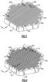
Figure 4 illustrates another example of a substrate that has a serpentine groove with a sine wave profile. -
Figure 5 illustrates another example of a substrate that has a serpentine groove with dimples. -
Figure 1 schematically illustrates agas turbine engine 20. Thegas turbine engine 20 is disclosed herein as a two-spool turbofan that generally incorporates afan section 22, acompressor section 24, acombustor section 26 and aturbine section 28. Thefan section 22 drives air along a bypass flow path B in a bypass duct defined within ahousing 15 such as a fan case or nacelle, and also drives air along a core flow path C for compression and communication into thecombustor section 26 then expansion through theturbine section 28. Although depicted as a two-spool turbofan gas turbine engine in the disclosed non-limiting embodiment, it should be understood that the concepts described herein are not limited to use with two-spool turbofans as the teachings may be applied to other types of turbine engines including three-spool architectures. - The
exemplary engine 20 generally includes alow speed spool 30 and ahigh speed spool 32 mounted for rotation about an engine central longitudinal axis A relative to an enginestatic structure 36 viaseveral bearing systems 38. It should be understood that various bearingsystems 38 at various locations may alternatively or additionally be provided, and the location of bearingsystems 38 may be varied as appropriate to the application. - The
low speed spool 30 generally includes aninner shaft 40 that interconnects, a first (or low)pressure compressor 44 and a first (or low)pressure turbine 46. Theinner shaft 40 is connected to thefan 42 through a speed change mechanism, which in exemplarygas turbine engine 20 is illustrated as a gearedarchitecture 48 to drive afan 42 at a lower speed than thelow speed spool 30. Thehigh speed spool 32 includes anouter shaft 50 that interconnects a second (or high)pressure compressor 52 and a second (or high)pressure turbine 54. Acombustor 56 is arranged in theexemplary gas turbine 20 between thehigh pressure compressor 52 and thehigh pressure turbine 54. Amid-turbine frame 57 of the enginestatic structure 36 may be arranged generally between thehigh pressure turbine 54 and thelow pressure turbine 46. Themid-turbine frame 57 furthersupports bearing systems 38 in theturbine section 28. Theinner shaft 40 and theouter shaft 50 are concentric and rotate via bearingsystems 38 about the engine central longitudinal axis A which is collinear with their longitudinal axes. - The core airflow is compressed by the
low pressure compressor 44 then thehigh pressure compressor 52, mixed and burned with fuel in thecombustor 56, then expanded through thehigh pressure turbine 54 andlow pressure turbine 46. Themid-turbine frame 57 includesairfoils 59 which are in the core airflow path C. Theturbines low speed spool 30 andhigh speed spool 32 in response to the expansion. It will be appreciated that each of the positions of thefan section 22,compressor section 24,combustor section 26,turbine section 28, and fandrive gear system 48 may be varied. For example,gear system 48 may be located aft of the low pressure compressor, or aft of thecombustor section 26 or even aft ofturbine section 28, andfan 42 may be positioned forward or aft of the location ofgear system 48. - The
engine 20 in one example is a high-bypass geared aircraft engine. In a further example, theengine 20 bypass ratio is greater than about six (6), with an example embodiment being greater than about ten (10), and can be less than or equal to about 18.0, or more narrowly can be less than or equal to 16.0. The gearedarchitecture 48 is an epicyclic gear train, such as a planetary gear system or other gear system, with a gear reduction ratio of greater than about 2.3. The gear reduction ratio may be less than or equal to 4.0. Thelow pressure turbine 46 has a pressure ratio that is greater than about five. The low pressure turbine pressure ratio can be less than or equal to 13.0, or more narrowly less than or equal to 12.0. In one disclosed embodiment, theengine 20 bypass ratio is greater than about ten (10:1), the fan diameter is significantly larger than that of thelow pressure compressor 44, and thelow pressure turbine 46 has a pressure ratio that is greater than about five 5:1.Low pressure turbine 46 pressure ratio is pressure measured prior to an inlet oflow pressure turbine 46 as related to the pressure at the outlet of thelow pressure turbine 46 prior to an exhaust nozzle. The gearedarchitecture 48 may be an epicycle gear train, such as a planetary gear system or other gear system, with a gear reduction ratio of greater than about 2.3:1 and less than about 5:1. It should be understood, however, that the above parameters are only exemplary of one embodiment of a geared architecture engine and that the present invention is applicable to other gas turbine engines including direct drive turbofans. - A significant amount of thrust is provided by the bypass flow B due to the high bypass ratio. The
fan section 22 of theengine 20 is designed for a particular flight condition -- typically cruise at about 0.8 Mach and about 35,000 feet (10,668 meters). The flight condition of 0.8 Mach and 35,000 ft (10,668 meters), with the engine at its best fuel consumption - also known as "bucket cruise Thrust Specific Fuel Consumption ('TSFC')" - is the industry standard parameter of lbm of fuel being burned divided by lbf of thrust the engine produces at that minimum point. The engine parameters described above and those in this paragraph are measured at this condition unless otherwise specified. "Low fan pressure ratio" is the pressure ratio across the fan blade alone, without a Fan Exit Guide Vane ("FEGV") system. The low fan pressure ratio as disclosed herein according to one non-limiting embodiment is less than about 1.45, or more narrowly greater than or equal to 1.25. "Low corrected fan tip speed" is the actual fan tip speed in ft/sec divided by an industry standard temperature correction of [(Tram °R) / (518.7 °R)]0.5. The "Low corrected fan tip speed" as disclosed herein according to one non-limiting embodiment is less than about 1150.0 ft / second (350.5 meters/second), and can be greater than or equal to 1000.0 ft / second (304.8 meters/second). -
Figure 2 illustrates a representative portion of anarticle 60 from theengine 20. As an example, thearticle 60 may be, but is not limited to, a turbine blade, a turbine vane, a blade outer air seal, a combustor panel, or other article that is exposed to the high temperature combustion gases in theengine 20. - The
article 60 includes asubstrate 62 that has apre-bond surface 62a that may face towards the core flowpath C of theengine 20. Thesubstrate 62 is not particularly limited and may be, but is not limited to, a superalloy (e.g., a nickel- or cobalt-based alloy) or a ceramic material (e.g., a ceramic matrix composite or a monolithic ceramic). There is acoating 64 disposed on thesurface 62a, to enhance resistance to the high temperatures, resistance to environmental substances, or both. In this example, thecoating 64 is a multilayer coating that includes abond coat layer 64a andceramic layer 64b. In one example, thebond coat layer 64a is an intermetallic. For instance, the intermetallic may be MCrAlY, where the M includes at least one of nickel, cobalt, iron, or combinations thereof. In other examples, thebond coat layer 64a may be silica or combinations of silica with refractory phases. Theceramic layer 64b may include yttria stabilized with zirconia, hafnia, and/or gadolinia, gadolinia zirconate, molybdate, alumina, hafnia, silica, barium-magnesium-aluminosilicate, hafnium silicate, zirconium silicate, rare earth silicate, rare earth oxides, mullite, or combinations thereof. - The
surface 62a has aserpentine groove 66, and thecoating 64 is mechanically interlocked with theserpentine groove 66. As will be discussed below, theserpentine groove 66 is configured to enhance wetting during coating deposition, which in turn enhances bonding between thecoating 64 andsubstrate 62. -
Figure 3 illustrates a representative portion of thesubstrate 62 but without thecoating 64 so that theserpentine groove 66 is visible. Theserpentine groove 66 starts at afirst groove end 66a and extends continuously to asecond groove end 66b. Theserpentine groove 66 is continuous in that it is uninterrupted between theends 66a/66b. The continuity facilitates manufacturing because the tool or laser that is used to create thegroove 66 need not be raised or switch on/off as it traverses thesurface 62a to form thegroove 66. - The
serpentine groove 66 is also of uniform width (w) and of uniform depth (d; seeFigure 2 ) over the continuous length. The width (w) is the linear distance betweenside walls 66c (Figure 2 ) of theserpentine groove 66, and the depth (d) is the linear distance from thefloor 66d of theserpentine groove 66 totop surface 66e. Thegroove 66 has a ratio of the depth to the width that is 2:1 or less. In one example, the width is from 10 micrometers to 200 micrometers. In a further example, the width is from 20 micrometers to 100 micrometers. - The
serpentine groove 66 winds back-and-forth across thesurface 62a of thesubstrate 62 and includes a plurality ofbends 68 of at least 180 degrees. Thebends 68 definecoils 70, which are uniformly spaced-apart by a pitch distance (P). The pitch distance is substantially equal to the uniform width of thegroove 66. As used herein, "substantially equal" means equal within a tolerance of +/- 5%. In general, theserpentine groove 66 extends across a substantial portion of thesurface 62a of thesubstrate 62. In that regard, the pattern defined by theserpentine groove 66 may have at least 20 bends. - The
serpentine groove 66 provides enhanced bond strength between thecoating 64 and thesubstrate 62. For example, in comparison to a grit-blasted surface, theserpentine groove 66 may increase bond strength by a factor of approximately 2x and may increase spallation resistance by a factor of approximately 3x. -
Figure 4 illustrates another exampleserpentine groove 166. Theserpentine groove 166 is the same as theserpentine groove 66 except that it has asine wave profile 72 to further facilitate mechanical interlocking with thecoating 64. Additionally, thesine wave profile 72 facilitates isotropy in the wetting of thecoating 64 during deposition and thus also in the properties of thefinal coating 64. For instance, thecoils 70 in theserpentine groove 66 in the example ofFigure 2 extend straight in the x-direction, thus inducing an anisotropy associated with that direction. Thesine wave profile 72 in theserpentine groove 166, however, provides component directionalities in both the x- and y-directions, thereby inducing a greater isotropy in comparison to theserpentine groove 66. -
Figure 5 illustrates another exampleserpentine groove 266. Theserpentine groove 266 is the same as theserpentine groove 66 except that thegroove floor 66d hasdimples 74 that are uniformly spaced apart from each other along the continuous length of thegroove 266. For example, thedimples 74 are arranged serially along thegroove floor 66d in a repeated spacing or pattern of spacing. Thedimples 74 provide additional surface area to further facilitate mechanical interlocking with thecoating 64. It is to be appreciated that a further example includes a combination of thesine wave profile 72 and thedimples 74. - This character of the serpentine grooves disclosed herein is based on a physical model for dominant geometrical parameters to guide texture design for enhanced coating adherence and durability. From a thermodynamic standpoint, adhesion of a bi-material bond is the amount of energy required to create free surfaces by separating the interface. In the thermal equilibrium condition, the interface free energy γi between a coating particle and a solid substrate is given by the Young equation:


- Therefore, using the surface free energy of the coating and the measured contact angle between the coating particle droplet and the substrate, the adhesion energy of the coating/substrate bond can be calculated. The surface free energy, y, refers to the energy required to create new surfaces of the material is assumed to be in ambient air condition.
- The interface between two surfaces has a specific energy, called the interfacial energy, which is proportionate to interfacial area. To characterize the contact surface properties, the roughness factor, r, is defined:

- In practice, air can be trapped on the rough surface under the liquid. The Cassie-Baxter equation for the apparent contact angle with Cassie-Baxter formula , θCB, is:

- In the Cassie-Baxter wetting state, the role of Young's contact angle is investigated by plotting Eq. (4) with θY as a parameter. The difference between the apparent contact angle values of the hydrophobic (θY = 90°) surface and hydrophilic (θY = 0°) surface decreases as f decreases. This indicates that the contribution of the surface chemistry (θY) of a material on the liquid repellency (θ∗) diminishes as f1 gets smaller. In other words, regardless of how much surface area is increased, the top surface would always be hydrophobic. Therefore, the surface texture, as in the disclosed serpentine grooves, is designed to maintain the certain liquid-solid contact. Also, the increased surface roughness factor facilitates a texture that is hydrophilic. Therefore, for most machined surfaces with θY of ~60°, as long as f1 is maintained above 0.7, it is feasible to obtain a hydrophilic surface texture, and larger surface roughness factors are preferable.
- After surface texturing, the fine features (or air pockets) are present on the surfaces. When water-based coating or hydrophilic coating is spread over the surface to form the
coating 64, the liquid-solid contact area mainly depends on how much air is removed from the cavities on the surfaces in addition to the chemical interaction between coating and substrate surface. If the removal of air is lower than a certain level, the bond strength will be reduced accordingly. So, it is necessary to have good wettability on the surface to allow the coating material to penetrate into theserpentine groove 66/166/266 to enhance the bond strength through mechanical interlock. Thus, to maintain certain level of liquid-solid contact and ensure a satisfactory level of bond strength, texture geometries of the serpentine grooves are defined to ensure the removal of air from the cavities on the surfaces. - Although a combination of features is shown in the illustrated examples, not all of them need to be combined to realize the benefits of various embodiments of this disclosure. In other words, a system designed according to an embodiment of this disclosure will not necessarily include all of the features shown in any one of the Figures or all of the portions schematically shown in the Figures. Moreover, selected features of one example embodiment may be combined with selected features of other example embodiments.
- The preceding description is exemplary rather than limiting in nature. Variations and modifications to the disclosed examples may become apparent to those skilled in the art that do not necessarily depart from this disclosure. The scope of legal protection given to this disclosure can only be determined by studying the following claims.
Claims (15)
- A gas turbine engine article (60) comprising:a substrate (62) including a pre-bond surface (62a) having a serpentine groove (66; 166; 266); anda coating (64) disposed on the pre-bond surface (62a) and mechanically interlocking with the serpentine groove (66; 166; 266).
- The gas turbine engine article (60) as recited in claim 1, wherein the serpentine groove (66; 16; 266) is of continuous length from a first groove end (66a) to a second groove end (66b).
- The gas turbine engine article (60) as recited in claim 1 or 2, wherein the serpentine groove (66; 166; 266) includes a plurality of bends (68) of at least 180 degrees.
- The gas turbine engine article (60) as recited in claim 3, wherein the plurality of bends (68) has at least 20 bends (68).
- The gas turbine engine article (60) as recited in claim 2 or as recited in claim 3 or 4 as dependent on claim 2, wherein the serpentine groove (66; 166; 266) is of uniform width (w) over the continuous length.
- The gas turbine engine article (60) as recited in claim 2 or as recited in any of claims 3 to 5 as dependent on claim 2, wherein the serpentine groove (66; 166) is of uniform depth (d) over the continuous length.
- The gas turbine engine article (60) as recited in claim 6 as dependent on claim 5, wherein a ratio of the uniform depth (d) to the uniform width (w) is 2:1 or less.
- The gas turbine engine article (60) as recited in any preceding claim, wherein the serpentine groove (66; 166; 266) defines coils (70), and the coils (70) are uniformly spaced apart by a pitch distance (P).
- The gas turbine engine article (60) as recited in claim 8 as directly or indirectly dependent on claim 5, wherein the pitch distance (P) is substantially equal to the uniform width (w).
- The gas turbine engine article (60) as recited in claim 5 or any of claims 6 to 9 as directly or indirectly dependent on claim 5, wherein the uniform width (w) is from 10 micrometers to 200 micrometers, optionally from 20 micrometers to 100 micrometers.
- The gas turbine engine article (60) as recited in claim 2 or as recited in claims 3, 4, 5, 8 ,9 or 10 as dependent on claim 2, but not dependent on claim 6, wherein the serpentine groove (266) has a groove floor (66d), and the groove floor (66d) includes dimples (74) that are spaced apart from each other along the continuous length.
- The gas turbine engine article (60) as recited in any preceding claim, wherein the serpentine groove (166) has a sine wave profile (72).
- The gas turbine engine article (60) as recited in any preceding claim, wherein the coating (64) includes an intermetallic layer (64a) and a ceramic layer (64b).
- The gas turbine engine article (60) as recited in any preceding claim, where the pre-bond surface (62a) has a Young's contact angle θY of approximately 60° and a fraction of the pre-bond surface (62a) wetted versus unwetted is at least 0.7.
- A gas turbine engine (20) comprising:a compressor section (24);a combustor (56) in fluid communication with the compressor section (24); anda turbine section (28) in fluid communication with the combustor (56), the turbine section (28) including a plurality of articles (60) as recited in any preceding claim.
Applications Claiming Priority (1)
| Application Number | Priority Date | Filing Date | Title |
|---|---|---|---|
| US17/587,246 US11828196B2 (en) | 2022-01-28 | 2022-01-28 | Gas turbine engine article with serpentine groove for coating interlock |
Publications (1)
| Publication Number | Publication Date |
|---|---|
| EP4219905A1 true EP4219905A1 (en) | 2023-08-02 |
Family
ID=85122051
Family Applications (1)
| Application Number | Title | Priority Date | Filing Date |
|---|---|---|---|
| EP23153534.5A Pending EP4219905A1 (en) | 2022-01-28 | 2023-01-26 | Gas turbine engine article with serpentine groove for coating interlock |
Country Status (2)
| Country | Link |
|---|---|
| US (1) | US11828196B2 (en) |
| EP (1) | EP4219905A1 (en) |
Citations (6)
| Publication number | Priority date | Publication date | Assignee | Title |
|---|---|---|---|---|
| CN106232945A (en) * | 2014-02-25 | 2016-12-14 | 西门子能源公司 | The abradable layer of turbine with terrace, gradual worn area ridge |
| US20170175560A1 (en) * | 2014-02-25 | 2017-06-22 | Siemens Aktiengesellschaft | Turbine abradable layer with airflow directing pixelated surface feature patterns |
| US20180066527A1 (en) * | 2015-02-18 | 2018-03-08 | Siemens Aktiengesellschaft | Turbine component thermal barrier coating with vertically aligned, engineered surface and multifurcated groove features |
| WO2018164693A1 (en) * | 2017-03-10 | 2018-09-13 | Siemens Aktiengesellschaft | Three-dimensional printing of ceramic fiber composite structures for improved thermal barrier coating adhesion |
| EP3401506A2 (en) * | 2017-05-11 | 2018-11-14 | General Electric Company | Cmc components having microchannels and methods for forming microchannels in cmc components |
| US10711794B2 (en) * | 2016-11-17 | 2020-07-14 | Raytheon Technologies Corporation | Airfoil with geometrically segmented coating section having mechanical secondary bonding feature |
Family Cites Families (8)
| Publication number | Priority date | Publication date | Assignee | Title |
|---|---|---|---|---|
| US20130017072A1 (en) * | 2011-07-14 | 2013-01-17 | General Electric Company | Pattern-abradable/abrasive coatings for steam turbine stationary component surfaces |
| CN103266295B (en) | 2013-05-23 | 2015-10-07 | 广州有色金属研究院 | A kind of thermal barrier coating by laser surface modifying method |
| US9151175B2 (en) * | 2014-02-25 | 2015-10-06 | Siemens Aktiengesellschaft | Turbine abradable layer with progressive wear zone multi level ridge arrays |
| US9884393B2 (en) * | 2015-10-20 | 2018-02-06 | General Electric Company | Repair methods utilizing additively manufacturing for rotor blades and components |
| FR3044946B1 (en) * | 2015-12-14 | 2018-01-12 | Safran Aircraft Engines | ABRADABLE COATING WITH VARIABLE DENSITY |
| CN109913801A (en) | 2019-04-24 | 2019-06-21 | 苏州大学 | Preparation method of plasmon-assisted laser-textured PVD coating on substrate surface |
| CN110666356B (en) | 2019-10-15 | 2021-04-02 | 中国民用航空飞行学院 | A kind of method of laser etching aluminum alloy surface texturing |
| CN113652687B (en) | 2021-08-16 | 2022-09-20 | 西南交通大学 | Thermal barrier coating textured anti-sticking surface and preparation method thereof |
-
2022
- 2022-01-28 US US17/587,246 patent/US11828196B2/en active Active
-
2023
- 2023-01-26 EP EP23153534.5A patent/EP4219905A1/en active Pending
Patent Citations (6)
| Publication number | Priority date | Publication date | Assignee | Title |
|---|---|---|---|---|
| CN106232945A (en) * | 2014-02-25 | 2016-12-14 | 西门子能源公司 | The abradable layer of turbine with terrace, gradual worn area ridge |
| US20170175560A1 (en) * | 2014-02-25 | 2017-06-22 | Siemens Aktiengesellschaft | Turbine abradable layer with airflow directing pixelated surface feature patterns |
| US20180066527A1 (en) * | 2015-02-18 | 2018-03-08 | Siemens Aktiengesellschaft | Turbine component thermal barrier coating with vertically aligned, engineered surface and multifurcated groove features |
| US10711794B2 (en) * | 2016-11-17 | 2020-07-14 | Raytheon Technologies Corporation | Airfoil with geometrically segmented coating section having mechanical secondary bonding feature |
| WO2018164693A1 (en) * | 2017-03-10 | 2018-09-13 | Siemens Aktiengesellschaft | Three-dimensional printing of ceramic fiber composite structures for improved thermal barrier coating adhesion |
| EP3401506A2 (en) * | 2017-05-11 | 2018-11-14 | General Electric Company | Cmc components having microchannels and methods for forming microchannels in cmc components |
Also Published As
| Publication number | Publication date |
|---|---|
| US11828196B2 (en) | 2023-11-28 |
| US20230243269A1 (en) | 2023-08-03 |
Similar Documents
| Publication | Publication Date | Title |
|---|---|---|
| EP3071727B1 (en) | Airfoil having a variable coating | |
| EP3336314B1 (en) | Airfoil with geometrically segmented coating section having mechanical secondary bonding feature | |
| EP3323984B1 (en) | Airfoil with geometrically segmented coating section | |
| EP3351729B1 (en) | Gas turbine engine component and corresponding gas turbine engine | |
| EP3323982A1 (en) | Airfoil, gas turbine engine having such airfoil and method of assembling an airfoil | |
| EP3323994A1 (en) | Airfoil with seal between endwall and airfoil section | |
| EP3323986B1 (en) | Airfoil with geometrically segmented coating section | |
| EP4219905A1 (en) | Gas turbine engine article with serpentine groove for coating interlock | |
| EP4379192A1 (en) | Seal slot with coating | |
| EP4379191A1 (en) | Seal slot with coating and method of coating a seal slot | |
| EP3323992A1 (en) | Airfoil with panel and side edge cooling | |
| EP2971689B1 (en) | Multiple coating configuration | |
| EP3040616A2 (en) | Combustor wall with metallic coating on cold side | |
| EP4403748A1 (en) | Sealing between ceramic and metallic component of a gas turbine engine | |
| EP4607000A2 (en) | Ceramic component with support structure | |
| EP4386181A1 (en) | Gas turbine engine coating with thermal protection | |
| EP4386180A1 (en) | Gas turbine engine coating with thermal protection | |
| EP4385968A1 (en) | Article and method of making a ceramic matrix composite article | |
| EP4361400A1 (en) | Seal with coating and method of fabricating | |
| EP3556998B1 (en) | Air seal having gaspath portion with geometrically segmented coating | |
| EP4317109A1 (en) | Ceramic matrix composite article and method of making the same |
Legal Events
| Date | Code | Title | Description |
|---|---|---|---|
| PUAI | Public reference made under article 153(3) epc to a published international application that has entered the european phase |
Free format text: ORIGINAL CODE: 0009012 |
|
| STAA | Information on the status of an ep patent application or granted ep patent |
Free format text: STATUS: THE APPLICATION HAS BEEN PUBLISHED |
|
| AK | Designated contracting states |
Kind code of ref document: A1 Designated state(s): AL AT BE BG CH CY CZ DE DK EE ES FI FR GB GR HR HU IE IS IT LI LT LU LV MC ME MK MT NL NO PL PT RO RS SE SI SK SM TR |
|
| RAP3 | Party data changed (applicant data changed or rights of an application transferred) |
Owner name: RTX CORPORATION |
|
| STAA | Information on the status of an ep patent application or granted ep patent |
Free format text: STATUS: REQUEST FOR EXAMINATION WAS MADE |
|
| 17P | Request for examination filed |
Effective date: 20240131 |
|
| RBV | Designated contracting states (corrected) |
Designated state(s): AL AT BE BG CH CY CZ DE DK EE ES FI FR GB GR HR HU IE IS IT LI LT LU LV MC ME MK MT NL NO PL PT RO RS SE SI SK SM TR |
|
| STAA | Information on the status of an ep patent application or granted ep patent |
Free format text: STATUS: EXAMINATION IS IN PROGRESS |
|
| 17Q | First examination report despatched |
Effective date: 20250729 |