EP4317109A1 - Ceramic matrix composite article and method of making the same - Google Patents
Ceramic matrix composite article and method of making the same Download PDFInfo
- Publication number
- EP4317109A1 EP4317109A1 EP23188475.0A EP23188475A EP4317109A1 EP 4317109 A1 EP4317109 A1 EP 4317109A1 EP 23188475 A EP23188475 A EP 23188475A EP 4317109 A1 EP4317109 A1 EP 4317109A1
- Authority
- EP
- European Patent Office
- Prior art keywords
- ceramic
- interface coating
- matrix
- layer
- secondary interface
- Prior art date
- Legal status (The legal status is an assumption and is not a legal conclusion. Google has not performed a legal analysis and makes no representation as to the accuracy of the status listed.)
- Pending
Links
- 239000011153 ceramic matrix composite Substances 0.000 title claims abstract description 14
- 238000004519 manufacturing process Methods 0.000 title claims abstract description 5
- 238000000576 coating method Methods 0.000 claims abstract description 66
- 239000011248 coating agent Substances 0.000 claims abstract description 64
- 239000011159 matrix material Substances 0.000 claims abstract description 61
- 239000000919 ceramic Substances 0.000 claims abstract description 48
- 230000002787 reinforcement Effects 0.000 claims abstract description 19
- 239000000835 fiber Substances 0.000 claims description 18
- 238000000034 method Methods 0.000 claims description 17
- VYPSYNLAJGMNEJ-UHFFFAOYSA-N Silicium dioxide Chemical compound O=[Si]=O VYPSYNLAJGMNEJ-UHFFFAOYSA-N 0.000 claims description 8
- 229910052582 BN Inorganic materials 0.000 claims description 5
- PZNSFCLAULLKQX-UHFFFAOYSA-N Boron nitride Chemical compound N#B PZNSFCLAULLKQX-UHFFFAOYSA-N 0.000 claims description 5
- 239000000377 silicon dioxide Substances 0.000 claims description 4
- 230000008595 infiltration Effects 0.000 claims description 3
- 238000001764 infiltration Methods 0.000 claims description 3
- 239000000126 substance Substances 0.000 claims description 3
- 230000001419 dependent effect Effects 0.000 claims 3
- 239000000446 fuel Substances 0.000 description 5
- 239000007800 oxidant agent Substances 0.000 description 4
- 230000007613 environmental effect Effects 0.000 description 3
- 239000000463 material Substances 0.000 description 3
- 230000001590 oxidative effect Effects 0.000 description 3
- 230000004224 protection Effects 0.000 description 3
- 230000009467 reduction Effects 0.000 description 3
- 230000001902 propagating effect Effects 0.000 description 2
- 230000003068 static effect Effects 0.000 description 2
- 230000035882 stress Effects 0.000 description 2
- 230000008901 benefit Effects 0.000 description 1
- 230000015556 catabolic process Effects 0.000 description 1
- 229910010293 ceramic material Inorganic materials 0.000 description 1
- 230000008859 change Effects 0.000 description 1
- 238000002485 combustion reaction Methods 0.000 description 1
- 238000004891 communication Methods 0.000 description 1
- 239000002131 composite material Substances 0.000 description 1
- 230000006835 compression Effects 0.000 description 1
- 238000007906 compression Methods 0.000 description 1
- 238000012937 correction Methods 0.000 description 1
- 238000006731 degradation reaction Methods 0.000 description 1
- 230000008021 deposition Effects 0.000 description 1
- 230000004069 differentiation Effects 0.000 description 1
- 230000006353 environmental stress Effects 0.000 description 1
- 238000003754 machining Methods 0.000 description 1
- 230000007246 mechanism Effects 0.000 description 1
- 238000012986 modification Methods 0.000 description 1
- 230000004048 modification Effects 0.000 description 1
- 239000002245 particle Substances 0.000 description 1
- 230000037361 pathway Effects 0.000 description 1
- 238000012805 post-processing Methods 0.000 description 1
- 230000008569 process Effects 0.000 description 1
- 230000009979 protective mechanism Effects 0.000 description 1
- 230000004044 response Effects 0.000 description 1
- HBMJWWWQQXIZIP-UHFFFAOYSA-N silicon carbide Chemical compound [Si+]#[C-] HBMJWWWQQXIZIP-UHFFFAOYSA-N 0.000 description 1
- 229910010271 silicon carbide Inorganic materials 0.000 description 1
- 238000012546 transfer Methods 0.000 description 1
Images


Classifications
-
- F—MECHANICAL ENGINEERING; LIGHTING; HEATING; WEAPONS; BLASTING
- F01—MACHINES OR ENGINES IN GENERAL; ENGINE PLANTS IN GENERAL; STEAM ENGINES
- F01D—NON-POSITIVE DISPLACEMENT MACHINES OR ENGINES, e.g. STEAM TURBINES
- F01D25/00—Component parts, details, or accessories, not provided for in, or of interest apart from, other groups
- F01D25/005—Selecting particular materials
-
- C—CHEMISTRY; METALLURGY
- C04—CEMENTS; CONCRETE; ARTIFICIAL STONE; CERAMICS; REFRACTORIES
- C04B—LIME, MAGNESIA; SLAG; CEMENTS; COMPOSITIONS THEREOF, e.g. MORTARS, CONCRETE OR LIKE BUILDING MATERIALS; ARTIFICIAL STONE; CERAMICS; REFRACTORIES; TREATMENT OF NATURAL STONE
- C04B35/00—Shaped ceramic products characterised by their composition; Ceramics compositions; Processing powders of inorganic compounds preparatory to the manufacturing of ceramic products
- C04B35/622—Forming processes; Processing powders of inorganic compounds preparatory to the manufacturing of ceramic products
- C04B35/626—Preparing or treating the powders individually or as batches ; preparing or treating macroscopic reinforcing agents for ceramic products, e.g. fibres; mechanical aspects section B
- C04B35/628—Coating the powders or the macroscopic reinforcing agents
- C04B35/62894—Coating the powders or the macroscopic reinforcing agents with more than one coating layer
-
- C—CHEMISTRY; METALLURGY
- C04—CEMENTS; CONCRETE; ARTIFICIAL STONE; CERAMICS; REFRACTORIES
- C04B—LIME, MAGNESIA; SLAG; CEMENTS; COMPOSITIONS THEREOF, e.g. MORTARS, CONCRETE OR LIKE BUILDING MATERIALS; ARTIFICIAL STONE; CERAMICS; REFRACTORIES; TREATMENT OF NATURAL STONE
- C04B35/00—Shaped ceramic products characterised by their composition; Ceramics compositions; Processing powders of inorganic compounds preparatory to the manufacturing of ceramic products
- C04B35/622—Forming processes; Processing powders of inorganic compounds preparatory to the manufacturing of ceramic products
- C04B35/626—Preparing or treating the powders individually or as batches ; preparing or treating macroscopic reinforcing agents for ceramic products, e.g. fibres; mechanical aspects section B
- C04B35/628—Coating the powders or the macroscopic reinforcing agents
- C04B35/62844—Coating fibres
- C04B35/62847—Coating fibres with oxide ceramics
- C04B35/62849—Silica or silicates
-
- C—CHEMISTRY; METALLURGY
- C04—CEMENTS; CONCRETE; ARTIFICIAL STONE; CERAMICS; REFRACTORIES
- C04B—LIME, MAGNESIA; SLAG; CEMENTS; COMPOSITIONS THEREOF, e.g. MORTARS, CONCRETE OR LIKE BUILDING MATERIALS; ARTIFICIAL STONE; CERAMICS; REFRACTORIES; TREATMENT OF NATURAL STONE
- C04B35/00—Shaped ceramic products characterised by their composition; Ceramics compositions; Processing powders of inorganic compounds preparatory to the manufacturing of ceramic products
- C04B35/622—Forming processes; Processing powders of inorganic compounds preparatory to the manufacturing of ceramic products
- C04B35/626—Preparing or treating the powders individually or as batches ; preparing or treating macroscopic reinforcing agents for ceramic products, e.g. fibres; mechanical aspects section B
- C04B35/628—Coating the powders or the macroscopic reinforcing agents
- C04B35/62844—Coating fibres
- C04B35/62857—Coating fibres with non-oxide ceramics
- C04B35/62865—Nitrides
- C04B35/62868—Boron nitride
-
- C—CHEMISTRY; METALLURGY
- C04—CEMENTS; CONCRETE; ARTIFICIAL STONE; CERAMICS; REFRACTORIES
- C04B—LIME, MAGNESIA; SLAG; CEMENTS; COMPOSITIONS THEREOF, e.g. MORTARS, CONCRETE OR LIKE BUILDING MATERIALS; ARTIFICIAL STONE; CERAMICS; REFRACTORIES; TREATMENT OF NATURAL STONE
- C04B35/00—Shaped ceramic products characterised by their composition; Ceramics compositions; Processing powders of inorganic compounds preparatory to the manufacturing of ceramic products
- C04B35/622—Forming processes; Processing powders of inorganic compounds preparatory to the manufacturing of ceramic products
- C04B35/626—Preparing or treating the powders individually or as batches ; preparing or treating macroscopic reinforcing agents for ceramic products, e.g. fibres; mechanical aspects section B
- C04B35/628—Coating the powders or the macroscopic reinforcing agents
- C04B35/62884—Coating the powders or the macroscopic reinforcing agents by gas phase techniques
-
- C—CHEMISTRY; METALLURGY
- C04—CEMENTS; CONCRETE; ARTIFICIAL STONE; CERAMICS; REFRACTORIES
- C04B—LIME, MAGNESIA; SLAG; CEMENTS; COMPOSITIONS THEREOF, e.g. MORTARS, CONCRETE OR LIKE BUILDING MATERIALS; ARTIFICIAL STONE; CERAMICS; REFRACTORIES; TREATMENT OF NATURAL STONE
- C04B35/00—Shaped ceramic products characterised by their composition; Ceramics compositions; Processing powders of inorganic compounds preparatory to the manufacturing of ceramic products
- C04B35/622—Forming processes; Processing powders of inorganic compounds preparatory to the manufacturing of ceramic products
- C04B35/626—Preparing or treating the powders individually or as batches ; preparing or treating macroscopic reinforcing agents for ceramic products, e.g. fibres; mechanical aspects section B
- C04B35/628—Coating the powders or the macroscopic reinforcing agents
- C04B35/62897—Coatings characterised by their thickness
-
- C—CHEMISTRY; METALLURGY
- C04—CEMENTS; CONCRETE; ARTIFICIAL STONE; CERAMICS; REFRACTORIES
- C04B—LIME, MAGNESIA; SLAG; CEMENTS; COMPOSITIONS THEREOF, e.g. MORTARS, CONCRETE OR LIKE BUILDING MATERIALS; ARTIFICIAL STONE; CERAMICS; REFRACTORIES; TREATMENT OF NATURAL STONE
- C04B35/00—Shaped ceramic products characterised by their composition; Ceramics compositions; Processing powders of inorganic compounds preparatory to the manufacturing of ceramic products
- C04B35/71—Ceramic products containing macroscopic reinforcing agents
- C04B35/78—Ceramic products containing macroscopic reinforcing agents containing non-metallic materials
- C04B35/80—Fibres, filaments, whiskers, platelets, or the like
-
- C—CHEMISTRY; METALLURGY
- C04—CEMENTS; CONCRETE; ARTIFICIAL STONE; CERAMICS; REFRACTORIES
- C04B—LIME, MAGNESIA; SLAG; CEMENTS; COMPOSITIONS THEREOF, e.g. MORTARS, CONCRETE OR LIKE BUILDING MATERIALS; ARTIFICIAL STONE; CERAMICS; REFRACTORIES; TREATMENT OF NATURAL STONE
- C04B41/00—After-treatment of mortars, concrete, artificial stone or ceramics; Treatment of natural stone
- C04B41/45—Coating or impregnating, e.g. injection in masonry, partial coating of green or fired ceramics, organic coating compositions for adhering together two concrete elements
- C04B41/50—Coating or impregnating, e.g. injection in masonry, partial coating of green or fired ceramics, organic coating compositions for adhering together two concrete elements with inorganic materials
- C04B41/5025—Coating or impregnating, e.g. injection in masonry, partial coating of green or fired ceramics, organic coating compositions for adhering together two concrete elements with inorganic materials with ceramic materials
- C04B41/5035—Silica
-
- C—CHEMISTRY; METALLURGY
- C04—CEMENTS; CONCRETE; ARTIFICIAL STONE; CERAMICS; REFRACTORIES
- C04B—LIME, MAGNESIA; SLAG; CEMENTS; COMPOSITIONS THEREOF, e.g. MORTARS, CONCRETE OR LIKE BUILDING MATERIALS; ARTIFICIAL STONE; CERAMICS; REFRACTORIES; TREATMENT OF NATURAL STONE
- C04B41/00—After-treatment of mortars, concrete, artificial stone or ceramics; Treatment of natural stone
- C04B41/45—Coating or impregnating, e.g. injection in masonry, partial coating of green or fired ceramics, organic coating compositions for adhering together two concrete elements
- C04B41/50—Coating or impregnating, e.g. injection in masonry, partial coating of green or fired ceramics, organic coating compositions for adhering together two concrete elements with inorganic materials
- C04B41/5053—Coating or impregnating, e.g. injection in masonry, partial coating of green or fired ceramics, organic coating compositions for adhering together two concrete elements with inorganic materials non-oxide ceramics
- C04B41/5062—Borides, Nitrides or Silicides
- C04B41/5064—Boron nitride
-
- C—CHEMISTRY; METALLURGY
- C04—CEMENTS; CONCRETE; ARTIFICIAL STONE; CERAMICS; REFRACTORIES
- C04B—LIME, MAGNESIA; SLAG; CEMENTS; COMPOSITIONS THEREOF, e.g. MORTARS, CONCRETE OR LIKE BUILDING MATERIALS; ARTIFICIAL STONE; CERAMICS; REFRACTORIES; TREATMENT OF NATURAL STONE
- C04B41/00—After-treatment of mortars, concrete, artificial stone or ceramics; Treatment of natural stone
- C04B41/80—After-treatment of mortars, concrete, artificial stone or ceramics; Treatment of natural stone of only ceramics
- C04B41/81—Coating or impregnation
- C04B41/85—Coating or impregnation with inorganic materials
- C04B41/87—Ceramics
-
- C—CHEMISTRY; METALLURGY
- C04—CEMENTS; CONCRETE; ARTIFICIAL STONE; CERAMICS; REFRACTORIES
- C04B—LIME, MAGNESIA; SLAG; CEMENTS; COMPOSITIONS THEREOF, e.g. MORTARS, CONCRETE OR LIKE BUILDING MATERIALS; ARTIFICIAL STONE; CERAMICS; REFRACTORIES; TREATMENT OF NATURAL STONE
- C04B2235/00—Aspects relating to ceramic starting mixtures or sintered ceramic products
- C04B2235/02—Composition of constituents of the starting material or of secondary phases of the final product
- C04B2235/30—Constituents and secondary phases not being of a fibrous nature
- C04B2235/34—Non-metal oxides, non-metal mixed oxides, or salts thereof that form the non-metal oxides upon heating, e.g. carbonates, nitrates, (oxy)hydroxides, chlorides
- C04B2235/3418—Silicon oxide, silicic acids, or oxide forming salts thereof, e.g. silica sol, fused silica, silica fume, cristobalite, quartz or flint
-
- C—CHEMISTRY; METALLURGY
- C04—CEMENTS; CONCRETE; ARTIFICIAL STONE; CERAMICS; REFRACTORIES
- C04B—LIME, MAGNESIA; SLAG; CEMENTS; COMPOSITIONS THEREOF, e.g. MORTARS, CONCRETE OR LIKE BUILDING MATERIALS; ARTIFICIAL STONE; CERAMICS; REFRACTORIES; TREATMENT OF NATURAL STONE
- C04B2235/00—Aspects relating to ceramic starting mixtures or sintered ceramic products
- C04B2235/02—Composition of constituents of the starting material or of secondary phases of the final product
- C04B2235/30—Constituents and secondary phases not being of a fibrous nature
- C04B2235/38—Non-oxide ceramic constituents or additives
- C04B2235/3852—Nitrides, e.g. oxynitrides, carbonitrides, oxycarbonitrides, lithium nitride, magnesium nitride
- C04B2235/386—Boron nitrides
-
- C—CHEMISTRY; METALLURGY
- C04—CEMENTS; CONCRETE; ARTIFICIAL STONE; CERAMICS; REFRACTORIES
- C04B—LIME, MAGNESIA; SLAG; CEMENTS; COMPOSITIONS THEREOF, e.g. MORTARS, CONCRETE OR LIKE BUILDING MATERIALS; ARTIFICIAL STONE; CERAMICS; REFRACTORIES; TREATMENT OF NATURAL STONE
- C04B2235/00—Aspects relating to ceramic starting mixtures or sintered ceramic products
- C04B2235/02—Composition of constituents of the starting material or of secondary phases of the final product
- C04B2235/50—Constituents or additives of the starting mixture chosen for their shape or used because of their shape or their physical appearance
- C04B2235/52—Constituents or additives characterised by their shapes
- C04B2235/5208—Fibers
- C04B2235/5216—Inorganic
-
- F—MECHANICAL ENGINEERING; LIGHTING; HEATING; WEAPONS; BLASTING
- F05—INDEXING SCHEMES RELATING TO ENGINES OR PUMPS IN VARIOUS SUBCLASSES OF CLASSES F01-F04
- F05D—INDEXING SCHEME FOR ASPECTS RELATING TO NON-POSITIVE-DISPLACEMENT MACHINES OR ENGINES, GAS-TURBINES OR JET-PROPULSION PLANTS
- F05D2230/00—Manufacture
- F05D2230/30—Manufacture with deposition of material
- F05D2230/31—Layer deposition
-
- F—MECHANICAL ENGINEERING; LIGHTING; HEATING; WEAPONS; BLASTING
- F05—INDEXING SCHEMES RELATING TO ENGINES OR PUMPS IN VARIOUS SUBCLASSES OF CLASSES F01-F04
- F05D—INDEXING SCHEME FOR ASPECTS RELATING TO NON-POSITIVE-DISPLACEMENT MACHINES OR ENGINES, GAS-TURBINES OR JET-PROPULSION PLANTS
- F05D2300/00—Materials; Properties thereof
- F05D2300/20—Oxide or non-oxide ceramics
- F05D2300/22—Non-oxide ceramics
- F05D2300/222—Silicon
-
- F—MECHANICAL ENGINEERING; LIGHTING; HEATING; WEAPONS; BLASTING
- F05—INDEXING SCHEMES RELATING TO ENGINES OR PUMPS IN VARIOUS SUBCLASSES OF CLASSES F01-F04
- F05D—INDEXING SCHEME FOR ASPECTS RELATING TO NON-POSITIVE-DISPLACEMENT MACHINES OR ENGINES, GAS-TURBINES OR JET-PROPULSION PLANTS
- F05D2300/00—Materials; Properties thereof
- F05D2300/20—Oxide or non-oxide ceramics
- F05D2300/22—Non-oxide ceramics
- F05D2300/228—Nitrides
- F05D2300/2282—Nitrides of boron
-
- F—MECHANICAL ENGINEERING; LIGHTING; HEATING; WEAPONS; BLASTING
- F05—INDEXING SCHEMES RELATING TO ENGINES OR PUMPS IN VARIOUS SUBCLASSES OF CLASSES F01-F04
- F05D—INDEXING SCHEME FOR ASPECTS RELATING TO NON-POSITIVE-DISPLACEMENT MACHINES OR ENGINES, GAS-TURBINES OR JET-PROPULSION PLANTS
- F05D2300/00—Materials; Properties thereof
- F05D2300/60—Properties or characteristics given to material by treatment or manufacturing
- F05D2300/603—Composites; e.g. fibre-reinforced
- F05D2300/6033—Ceramic matrix composites [CMC]
-
- F—MECHANICAL ENGINEERING; LIGHTING; HEATING; WEAPONS; BLASTING
- F05—INDEXING SCHEMES RELATING TO ENGINES OR PUMPS IN VARIOUS SUBCLASSES OF CLASSES F01-F04
- F05D—INDEXING SCHEME FOR ASPECTS RELATING TO NON-POSITIVE-DISPLACEMENT MACHINES OR ENGINES, GAS-TURBINES OR JET-PROPULSION PLANTS
- F05D2300/00—Materials; Properties thereof
- F05D2300/60—Properties or characteristics given to material by treatment or manufacturing
- F05D2300/611—Coating
Definitions
- a gas turbine engine typically includes a fan section, a compressor section, a combustor section and a turbine section. Air entering the compressor section is compressed and delivered into the combustion section where it is mixed with fuel and ignited to generate a high-energy exhaust gas flow. The high-energy exhaust gas flow expands through the turbine section to drive the compressor and the fan section.
- the compressor section typically includes low and high pressure compressors, and the turbine section includes low and high pressure turbines.
- This disclosure relates to composite articles, such as those used in gas turbine engines, and methods of coating such articles.
- Components such as gas turbine engine components, may be subjected to high temperatures, corrosive and oxidative conditions, and elevated stress levels. Ceramic materials such as ceramic matrix composites may be suitable for use in such conditions.
- a method of making a ceramic matrix composite component according to an aspect of this disclosure includes arranging a plurality of ceramic-based reinforcements in an array, applying an interface coating to the ceramic-based reinforcements, applying a layer of ceramic-based matrix over the interface coating, and applying a secondary interface coating such that the secondary interface coating is separate and distinct from the layer of ceramic-based matrix.
- the layer of ceramic-based matrix is a first layer of ceramic-based matrix.
- the method also includes applying a second layer of ceramic-based matrix over the secondary interface coating.
- a thickness of the first layer of ceramic-based matrix is between about 5 and about 25 microns after the applying.
- a thickness of the second layer of ceramic-based matrix is between about 25 and about 50 microns thick after the applying.
- a sum total thickness of the first and second layers of ceramic-based matrix is between about 25 and about 150 microns after the applying.
- the applying steps are accomplished by chemical vapor infiltration (CVI).
- the plurality of ceramic-based reinforcements are fibers.
- a thickness of the interface coating is between 50 and 250 nanometers after the applying.
- a thickness of the secondary interface coating is between 50 and 250 nanometers after the applying.
- At least one of the interface coating and the secondary interface coating are boron nitride.
- the secondary interface coating is a silica-based oxide.
- a ceramic matrix composite component includes a plurality of ceramic-based reinforcements, an interface coating disposed on the ceramic-based reinforcements, a first layer of ceramic-based matrix disposed on the interface coating, a secondary interface coating disposed on the first layer of ceramic-based matrix, and a second layer of ceramic-based matrix disposed on the secondary interface coating.
- the secondary interface coating is separate and distinct from the first and second layers of ceramic-based matrix.
- a thickness of the interface coating is between 50 and 250 nanometers.
- a thickness of the secondary interface coating is between 50 and 250 nanometers.
- At least one of the interface coating and the secondary interface coating are boron nitride.
- the secondary interface coating is a silica-based oxide.
- a thickness of the first layer of ceramic-based matrix is between about 5 and about 25 microns.
- a thickness of the second layer of ceramic-based matrix is between about 25 and about 50 microns thick.
- a sum total thickness of the first and second layers of ceramic-based matrix is between about 25 and about 150 microns.
- the plurality of ceramic-based reinforcements are fibers.
- FIG. 1 schematically illustrates a gas turbine engine 20.
- the gas turbine engine 20 is disclosed herein as a two-spool turbofan that generally incorporates a fan section 22, a compressor section 24, a combustor section 26 and a turbine section 28.
- the fan section 22 drives air along a bypass flow path B in a bypass duct defined within a housing 15 such as a fan case or nacelle, and also drives air along a core flow path C for compression and communication into the combustor section 26 then expansion through the turbine section 28.
- the exemplary engine 20 generally includes a low speed spool 30 and a high speed spool 32 mounted for rotation about an engine central longitudinal axis A relative to an engine static structure 36 via several bearing systems 38. It should be understood that various bearing systems 38 at various locations may alternatively or additionally be provided, and the location of bearing systems 38 may be varied as appropriate to the application.
- the low speed spool 30 generally includes an inner shaft 40 that interconnects, a first (or low) pressure compressor 44 and a first (or low) pressure turbine 46.
- the inner shaft 40 is connected to the fan 42 through a speed change mechanism, which in exemplary gas turbine engine 20 is illustrated as a geared architecture 48 to drive a fan 42 at a lower speed than the low speed spool 30.
- the high speed spool 32 includes an outer shaft 50 that interconnects a second (or high) pressure compressor 52 and a second (or high) pressure turbine 54.
- a combustor 56 is arranged in the exemplary gas turbine 20 between the high pressure compressor 52 and the high pressure turbine 54.
- a mid-turbine frame 57 of the engine static structure 36 may be arranged generally between the high pressure turbine 54 and the low pressure turbine 46.
- the mid-turbine frame 57 further supports bearing systems 38 in the turbine section 28.
- the inner shaft 40 and the outer shaft 50 are concentric and rotate via bearing systems 38 about the engine central longitudinal axis A which is collinear with their longitudinal axes.
- the core airflow is compressed by the low pressure compressor 44 then the high pressure compressor 52, mixed and burned with fuel in the combustor 56, then expanded through the high pressure turbine 54 and low pressure turbine 46.
- the mid-turbine frame 57 includes airfoils 59 which are in the core airflow path C.
- the turbines 46, 54 rotationally drive the respective low speed spool 30 and high speed spool 32 in response to the expansion.
- gear system 48 may be located aft of the low pressure compressor, or aft of the combustor section 26 or even aft of turbine section 28, and fan 42 may be positioned forward or aft of the location of gear system 48.
- the engine 20 in one example is a high-bypass geared aircraft engine.
- the engine 20 bypass ratio is greater than about six (6), with an example embodiment being greater than about ten (10), and can be less than or equal to about 18.0, or more narrowly can be less than or equal to 16.0.
- the geared architecture 48 is an epicyclic gear train, such as a planetary gear system or other gear system, with a gear reduction ratio of greater than about 2.3.
- the gear reduction ratio may be less than or equal to 4.0.
- the low pressure turbine 46 has a pressure ratio that is greater than about five.
- the low pressure turbine pressure ratio can be less than or equal to 13.0, or more narrowly less than or equal to 12.0.
- the engine 20 bypass ratio is greater than about ten (10:1)
- the fan diameter is significantly larger than that of the low pressure compressor 44
- the low pressure turbine 46 has a pressure ratio that is greater than about five 5:1.
- Low pressure turbine 46 pressure ratio is pressure measured prior to an inlet of low pressure turbine 46 as related to the pressure at the outlet of the low pressure turbine 46 prior to an exhaust nozzle.
- the geared architecture 48 may be an epicycle gear train, such as a planetary gear system or other gear system, with a gear reduction ratio of greater than about 2.3:1 and less than about 5:1. It should be understood, however, that the above parameters are only exemplary of one embodiment of a geared architecture engine and that the present invention is applicable to other gas turbine engines including direct drive turbofans.
- the fan section 22 of the engine 20 is designed for a particular flight condition -- typically cruise at about 0.8 Mach and about 35,000 feet (10,668 meters).
- the flight condition of 0.8 Mach and 35,000 ft (10,668 meters), with the engine at its best fuel consumption - also known as "bucket cruise Thrust Specific Fuel Consumption ('TSFC')" - is the industry standard parameter of lbm of fuel being burned divided by lbf of thrust the engine produces at that minimum point.
- 'TSFC' Thrust Specific Fuel Consumption
- “Low fan pressure ratio” is the pressure ratio across the fan blade alone, without a Fan Exit Guide Vane (“FEGV”) system.
- the low fan pressure ratio as disclosed herein according to one non-limiting embodiment is less than about 1.45, or more narrowly greater than or equal to 1.25.
- Low corrected fan tip speed is the actual fan tip speed in ft/sec divided by an industry standard temperature correction of [(Tram °R) / (518.7 °R)] 0.5 .
- the "Low corrected fan tip speed" as disclosed herein according to one non-limiting embodiment is less than about 1150.0 ft / second (350.5 meters/second), and can be greater than or equal to 1000.0 ft / second (304.8 meters/second).
- FIG 2 schematically illustrates a prior art ceramic matrix composite ("CMC") article 100.
- the article 100 includes ceramic-based reinforcements 102 disposed in a ceramic-based matrix 104. Over its lifetime, the article 100 may be exposed to mechanical, temperature, and/or environmental stresses that can cause the matrix 104 to crack.
- An example crack C is shown in Figure 2 .
- the crack C will typically originate from a surface 105 of the article 100, providing a pathway for oxidant O ingress into the body of the article 100, which could lead to degradation of the matrix 104.
- the crack C may expose certain of the reinforcements 102, leaving the reinforcements 102 susceptible to environmental attack by the oxidants O.
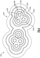
- Figures 3 and 4 show a crack-deflecting CMC article 200.
- the article 200 can be, for example, an airfoil in the compressor section 24 or turbine section 28, a combustor liner panel in the combustor section 26, a blade outer air seal, or other component that would benefit from the examples herein.
- the article 200 includes ceramic-based reinforcements 202 disposed in a ceramic-based matrix 204.
- the ceramic-based reinforcements 202 are fibers, but it should be understood that other reinforcements like particles, platelets, etc. are also contemplated.
- both the ceramic-based matrix 204 and the fibers 202 are silicon carbide, but other materials are also contemplated.
- the fibers 202 can be arranged within the matrix 204 in a variety of ways which are well-known in the art. For instance, the fibers 202 can be woven or braided, or can be arranged unidirectionally, multidirectionally, or randomly.
- the fibers 202 may include an interface coating 206 ( Figure 4 ).
- the interface coating 206 promotes load transfer between the fibers 202 and the matrix 204, and may in some examples provide environmental protection to the fibers 202.
- the interface coating 206 can be, for example, boron nitride. In general the interface coating 206 is a different material than the matrix 204. Other interface coatings 206 are known in the art. Even where the interface coating 206 provides a measure of environmental protection to the fibers 202, however, the protection may be limited in lifespan because the protective mechanism may include consumption of the interface coating 206.
- the fibers 202 are surrounded by a layer 204a of matrix.
- a secondary interface coating 208 is disposed on the matrix layer 204a.
- the secondary interface coating 208 may be boron nitride like the interface coating 206, but in other examples, can be a different material such as a thermally grown oxide, and in a more particular example a thermally grown oxide that is silica-based.
- the article 200 may include multiple alternating layers of secondary interface coating 208 and matrix 204. For instance, in the example of Figure 4 , there are four layers of matrix 204a/204b/204c/204d, each separated by a layer of secondary interface coating 208. In other examples, there may be up to 10 layers of matrix 204.
- the outermost layer of the article 200 is a layer of matrix 204.
- the interface coating 206 is between about 50 and about 250 nanometers thick.
- Each of the inner matrix layers 204a/204b/204c are between about 5 and about 25 microns thick.
- the outermost matrix layer 204d may be thicker than the inner matrix layers 204a/204b/204c, and may be between about 25 and about 50 microns thick.
- the total matrix 204 thickness e.g., the sum thickness of each of the matrix layers 204a/204b/204c/204d, is between about 25 and about 150 microns thick.
- Each layer of the secondary interface coating 208 is between about 50 and about 250 nanometers thick.
- a crack C1 may develop in the matrix 204, originating from a surface 205 of the article 200. However, once the crack C1 reaches a secondary interface coating 208 layer, the crack C1 is discouraged from propagating beyond the secondary interface coating 208. Stresses in the article 200 may cause other cracks such as cracks C2, C3, and C4 to form throughout the matrix 204. However, the cracks C2/C3/C4 are not aligned with one another, e.g., they tend to form in independent planes.
- each crack C2/C3/C4 is discouraged from propagating when it reaches a secondary interface coating 208 because of the discontinuity between the matrix layer 204a/204b/204c/204d and the secondary interface coating 208, e.g., because the matrix layer 204a/204b/204c/204d is a distinct layer from the secondary interface coating 208.
- any of the cracks, such as crack C4 spans across fibers 202, the size of each crack C2/C3/C4 is minimized and none of the cracks C2/C3/C4 are exposed to the surface 205 of the article 200. Therefore the cracks C2/C3/C4 do not allow ingress of oxidants into the matrix 204.
- the only crack C1 which is exposed to the surface 205 of the article 200 is smaller than the crack C discussed above and shown in Figure 2 . Accordingly, much of the article 200 is protected from oxidant attack as compared to the article 100 discussed above. Moreover, the smaller size of the crack C1 is a minimal debit to the mechanical integrity of the article 200 as compared to the crack C in article 100 as discussed above.
- Figure 5 shows a method 300 of making a crack-deflecting ceramic matrix composite article 200.
- fibers 202 are arranged or "layed up" in a desired configuration to form a fiber array.
- the interface coating 206 is applied to the fibers 202 by any known method, such as chemical vapor infiltration (CVI).
- CVI chemical vapor infiltration
- a layer 204a of matrix is applied to the fibers 202 by any known method, such as CVI.
- the secondary interface coating 208 is applied over the matrix layer 204a by any known method, such as CVI.
- steps 306 and 308 the process is interrupted after step 306 to provide a differentiation between the secondary interface coating 208 and the matrix layer 204a, that is, to provide a secondary interface coating 208 that is separate and distinct from the matrix layer 204a.
- Steps 306 and 308 may be repeated to form the desired number of matrix 204/secondary interface coating 208 layers.
- the final step is the deposition of matrix in step 306 such that the outermost layer is matrix 204.
- the fiber array may be optionally rigidized between any of the steps 302/304/306. Rigidization is well-known in the art.
- the article 200 may be subjected to post-processing steps such as machining and/or the application of coatings, which are well known in the art.
Abstract
A method of making a ceramic matrix composite component (200) includes arranging a plurality of ceramic-based reinforcements (202) in an array, applying an interface coating (206) to the ceramic-based reinforcements (202), applying a layer (204a) of ceramic-based matrix (204) over the interface coating (206), and applying a secondary interface coating (208) such that the secondary interface coating (208) is separate and distinct from the layer (204a) of ceramic-based matrix (204). A ceramic matrix composite component (202) is also disclosed.
Description
- A gas turbine engine typically includes a fan section, a compressor section, a combustor section and a turbine section. Air entering the compressor section is compressed and delivered into the combustion section where it is mixed with fuel and ignited to generate a high-energy exhaust gas flow. The high-energy exhaust gas flow expands through the turbine section to drive the compressor and the fan section. The compressor section typically includes low and high pressure compressors, and the turbine section includes low and high pressure turbines.
- This disclosure relates to composite articles, such as those used in gas turbine engines, and methods of coating such articles. Components, such as gas turbine engine components, may be subjected to high temperatures, corrosive and oxidative conditions, and elevated stress levels. Ceramic materials such as ceramic matrix composites may be suitable for use in such conditions.
- A method of making a ceramic matrix composite component according to an aspect of this disclosure, among other possible things includes arranging a plurality of ceramic-based reinforcements in an array, applying an interface coating to the ceramic-based reinforcements, applying a layer of ceramic-based matrix over the interface coating, and applying a secondary interface coating such that the secondary interface coating is separate and distinct from the layer of ceramic-based matrix.
- In an example of the foregoing, the layer of ceramic-based matrix is a first layer of ceramic-based matrix. The method also includes applying a second layer of ceramic-based matrix over the secondary interface coating.
- In a further example of any of the foregoing, a thickness of the first layer of ceramic-based matrix is between about 5 and about 25 microns after the applying.
- In a further example of any of the foregoing, a thickness of the second layer of ceramic-based matrix is between about 25 and about 50 microns thick after the applying.
- In a further example of any of the foregoing, a sum total thickness of the first and second layers of ceramic-based matrix is between about 25 and about 150 microns after the applying.
- In a further example of any of the foregoing, the applying steps are accomplished by chemical vapor infiltration (CVI).
- In a further example of any of the foregoing, the plurality of ceramic-based reinforcements are fibers.
- In a further example of any of the foregoing, a thickness of the interface coating is between 50 and 250 nanometers after the applying.
- In a further example of any of the foregoing, a thickness of the secondary interface coating is between 50 and 250 nanometers after the applying.
- In a further example of any of the foregoing, at least one of the interface coating and the secondary interface coating are boron nitride.
- In a further example of any of the foregoing, the secondary interface coating is a silica-based oxide.
- A ceramic matrix composite component according to another aspect of this disclosure, among other possible things includes a plurality of ceramic-based reinforcements, an interface coating disposed on the ceramic-based reinforcements, a first layer of ceramic-based matrix disposed on the interface coating, a secondary interface coating disposed on the first layer of ceramic-based matrix, and a second layer of ceramic-based matrix disposed on the secondary interface coating. The secondary interface coating is separate and distinct from the first and second layers of ceramic-based matrix.
- In an example of the foregoing, a thickness of the interface coating is between 50 and 250 nanometers.
- In a further example of any of the foregoing, a thickness of the secondary interface coating is between 50 and 250 nanometers.
- In a further example of any of the foregoing, at least one of the interface coating and the secondary interface coating are boron nitride.
- In a further example of any of the foregoing, the secondary interface coating is a silica-based oxide.
- In a further example of any of the foregoing, a thickness of the first layer of ceramic-based matrix is between about 5 and about 25 microns.
- In a further example of any of the foregoing, a thickness of the second layer of ceramic-based matrix is between about 25 and about 50 microns thick.
- In a further example of any of the foregoing, a sum total thickness of the first and second layers of ceramic-based matrix is between about 25 and about 150 microns.
- In a further example of any of the foregoing, the plurality of ceramic-based reinforcements are fibers.
-
-
Figure 1 is a schematic view of an example gas turbine engine. -
Figure 2 schematically illustrates a prior art ceramic matrix composite article. -
Figure 3 schematically illustrates a crack-deflecting ceramic matrix composite article. -
Figures 4 illustrates a detail view of the ceramic matrix composite article ofFigure 3 . -
Figure 5 schematically illustrates a method of making a crack-defleting ceramic matrix composite article. -
Figure 1 schematically illustrates agas turbine engine 20. Thegas turbine engine 20 is disclosed herein as a two-spool turbofan that generally incorporates afan section 22, acompressor section 24, acombustor section 26 and aturbine section 28. Thefan section 22 drives air along a bypass flow path B in a bypass duct defined within ahousing 15 such as a fan case or nacelle, and also drives air along a core flow path C for compression and communication into thecombustor section 26 then expansion through theturbine section 28. Although depicted as a two-spool turbofan gas turbine engine in the disclosed non-limiting embodiment, it should be understood that the concepts described herein are not limited to use with two-spool turbofans as the teachings may be applied to other types of turbine engines including three-spool architectures. - The
exemplary engine 20 generally includes alow speed spool 30 and ahigh speed spool 32 mounted for rotation about an engine central longitudinal axis A relative to an enginestatic structure 36 viaseveral bearing systems 38. It should be understood thatvarious bearing systems 38 at various locations may alternatively or additionally be provided, and the location ofbearing systems 38 may be varied as appropriate to the application. - The
low speed spool 30 generally includes aninner shaft 40 that interconnects, a first (or low)pressure compressor 44 and a first (or low)pressure turbine 46. Theinner shaft 40 is connected to thefan 42 through a speed change mechanism, which in exemplarygas turbine engine 20 is illustrated as a gearedarchitecture 48 to drive afan 42 at a lower speed than thelow speed spool 30. Thehigh speed spool 32 includes anouter shaft 50 that interconnects a second (or high)pressure compressor 52 and a second (or high)pressure turbine 54. Acombustor 56 is arranged in theexemplary gas turbine 20 between thehigh pressure compressor 52 and thehigh pressure turbine 54. Amid-turbine frame 57 of the enginestatic structure 36 may be arranged generally between thehigh pressure turbine 54 and thelow pressure turbine 46. Themid-turbine frame 57 further supports bearingsystems 38 in theturbine section 28. Theinner shaft 40 and theouter shaft 50 are concentric and rotate viabearing systems 38 about the engine central longitudinal axis A which is collinear with their longitudinal axes. - The core airflow is compressed by the
low pressure compressor 44 then thehigh pressure compressor 52, mixed and burned with fuel in thecombustor 56, then expanded through thehigh pressure turbine 54 andlow pressure turbine 46. Themid-turbine frame 57 includesairfoils 59 which are in the core airflow path C. Theturbines low speed spool 30 andhigh speed spool 32 in response to the expansion. It will be appreciated that each of the positions of thefan section 22,compressor section 24,combustor section 26,turbine section 28, and fandrive gear system 48 may be varied. For example,gear system 48 may be located aft of the low pressure compressor, or aft of thecombustor section 26 or even aft ofturbine section 28, andfan 42 may be positioned forward or aft of the location ofgear system 48. - The
engine 20 in one example is a high-bypass geared aircraft engine. In a further example, theengine 20 bypass ratio is greater than about six (6), with an example embodiment being greater than about ten (10), and can be less than or equal to about 18.0, or more narrowly can be less than or equal to 16.0. The gearedarchitecture 48 is an epicyclic gear train, such as a planetary gear system or other gear system, with a gear reduction ratio of greater than about 2.3. The gear reduction ratio may be less than or equal to 4.0. Thelow pressure turbine 46 has a pressure ratio that is greater than about five. The low pressure turbine pressure ratio can be less than or equal to 13.0, or more narrowly less than or equal to 12.0. In one disclosed embodiment, theengine 20 bypass ratio is greater than about ten (10:1), the fan diameter is significantly larger than that of thelow pressure compressor 44, and thelow pressure turbine 46 has a pressure ratio that is greater than about five 5:1.Low pressure turbine 46 pressure ratio is pressure measured prior to an inlet oflow pressure turbine 46 as related to the pressure at the outlet of thelow pressure turbine 46 prior to an exhaust nozzle. The gearedarchitecture 48 may be an epicycle gear train, such as a planetary gear system or other gear system, with a gear reduction ratio of greater than about 2.3:1 and less than about 5:1. It should be understood, however, that the above parameters are only exemplary of one embodiment of a geared architecture engine and that the present invention is applicable to other gas turbine engines including direct drive turbofans. - A significant amount of thrust is provided by the bypass flow B due to the high bypass ratio. The
fan section 22 of theengine 20 is designed for a particular flight condition -- typically cruise at about 0.8 Mach and about 35,000 feet (10,668 meters). The flight condition of 0.8 Mach and 35,000 ft (10,668 meters), with the engine at its best fuel consumption - also known as "bucket cruise Thrust Specific Fuel Consumption ('TSFC')" - is the industry standard parameter of lbm of fuel being burned divided by lbf of thrust the engine produces at that minimum point. The engine parameters described above and those in this paragraph are measured at this condition unless otherwise specified. "Low fan pressure ratio" is the pressure ratio across the fan blade alone, without a Fan Exit Guide Vane ("FEGV") system. The low fan pressure ratio as disclosed herein according to one non-limiting embodiment is less than about 1.45, or more narrowly greater than or equal to 1.25. "Low corrected fan tip speed" is the actual fan tip speed in ft/sec divided by an industry standard temperature correction of [(Tram °R) / (518.7 °R)]0.5. The "Low corrected fan tip speed" as disclosed herein according to one non-limiting embodiment is less than about 1150.0 ft / second (350.5 meters/second), and can be greater than or equal to 1000.0 ft / second (304.8 meters/second). -
Figure 2 schematically illustrates a prior art ceramic matrix composite ("CMC")article 100. Thearticle 100 includes ceramic-basedreinforcements 102 disposed in a ceramic-basedmatrix 104. Over its lifetime, thearticle 100 may be exposed to mechanical, temperature, and/or environmental stresses that can cause thematrix 104 to crack. An example crack C is shown inFigure 2 . The crack C will typically originate from asurface 105 of thearticle 100, providing a pathway for oxidant O ingress into the body of thearticle 100, which could lead to degradation of thematrix 104. Moreover, the crack C may expose certain of thereinforcements 102, leaving thereinforcements 102 susceptible to environmental attack by the oxidants O. -
Figures 3 and4 show a crack-deflectingCMC article 200. Thearticle 200 can be, for example, an airfoil in thecompressor section 24 orturbine section 28, a combustor liner panel in thecombustor section 26, a blade outer air seal, or other component that would benefit from the examples herein. Thearticle 200 includes ceramic-basedreinforcements 202 disposed in a ceramic-basedmatrix 204. In this example, the ceramic-basedreinforcements 202 are fibers, but it should be understood that other reinforcements like particles, platelets, etc. are also contemplated. In a particular example, both the ceramic-basedmatrix 204 and thefibers 202 are silicon carbide, but other materials are also contemplated. Thefibers 202 can be arranged within thematrix 204 in a variety of ways which are well-known in the art. For instance, thefibers 202 can be woven or braided, or can be arranged unidirectionally, multidirectionally, or randomly. - The
fibers 202 may include an interface coating 206 (Figure 4 ). Theinterface coating 206 promotes load transfer between thefibers 202 and thematrix 204, and may in some examples provide environmental protection to thefibers 202. Theinterface coating 206 can be, for example, boron nitride. In general theinterface coating 206 is a different material than thematrix 204.Other interface coatings 206 are known in the art. Even where theinterface coating 206 provides a measure of environmental protection to thefibers 202, however, the protection may be limited in lifespan because the protective mechanism may include consumption of theinterface coating 206. - As shown in
Figure 4 , thefibers 202 are surrounded by alayer 204a of matrix. Asecondary interface coating 208 is disposed on thematrix layer 204a. Thesecondary interface coating 208 may be boron nitride like theinterface coating 206, but in other examples, can be a different material such as a thermally grown oxide, and in a more particular example a thermally grown oxide that is silica-based. Thearticle 200 may include multiple alternating layers ofsecondary interface coating 208 andmatrix 204. For instance, in the example ofFigure 4 , there are four layers ofmatrix 204a/204b/204c/204d, each separated by a layer ofsecondary interface coating 208. In other examples, there may be up to 10 layers ofmatrix 204. The outermost layer of thearticle 200 is a layer ofmatrix 204. - In a particular example, the
interface coating 206 is between about 50 and about 250 nanometers thick. Each of theinner matrix layers 204a/204b/204c are between about 5 and about 25 microns thick. Theoutermost matrix layer 204d may be thicker than theinner matrix layers 204a/204b/204c, and may be between about 25 and about 50 microns thick. Thetotal matrix 204 thickness, e.g., the sum thickness of each of thematrix layers 204a/204b/204c/204d, is between about 25 and about 150 microns thick. Each layer of thesecondary interface coating 208 is between about 50 and about 250 nanometers thick. - With continued reference to
Figure 3 , a crack C1 may develop in thematrix 204, originating from asurface 205 of thearticle 200. However, once the crack C1 reaches asecondary interface coating 208 layer, the crack C1 is discouraged from propagating beyond thesecondary interface coating 208. Stresses in thearticle 200 may cause other cracks such as cracks C2, C3, and C4 to form throughout thematrix 204. However, the cracks C2/C3/C4 are not aligned with one another, e.g., they tend to form in independent planes. Moreover, each crack C2/C3/C4 is discouraged from propagating when it reaches asecondary interface coating 208 because of the discontinuity between thematrix layer 204a/204b/204c/204d and thesecondary interface coating 208, e.g., because thematrix layer 204a/204b/204c/204d is a distinct layer from thesecondary interface coating 208. Even to the extent any of the cracks, such as crack C4, spans acrossfibers 202, the size of each crack C2/C3/C4 is minimized and none of the cracks C2/C3/C4 are exposed to thesurface 205 of thearticle 200. Therefore the cracks C2/C3/C4 do not allow ingress of oxidants into thematrix 204. - With the
secondary interface coating 208 provided betweenmatrix layers 204a/204b/204c/204d, the only crack C1 which is exposed to thesurface 205 of thearticle 200 is smaller than the crack C discussed above and shown inFigure 2 . Accordingly, much of thearticle 200 is protected from oxidant attack as compared to thearticle 100 discussed above. Moreover, the smaller size of the crack C1 is a minimal debit to the mechanical integrity of thearticle 200 as compared to the crack C inarticle 100 as discussed above. -
Figure 5 shows amethod 300 of making a crack-deflecting ceramic matrixcomposite article 200. Instep 302,fibers 202 are arranged or "layed up" in a desired configuration to form a fiber array. Instep 304, theinterface coating 206 is applied to thefibers 202 by any known method, such as chemical vapor infiltration (CVI). Instep 306, alayer 204a of matrix is applied to thefibers 202 by any known method, such as CVI. Instep 308, thesecondary interface coating 208 is applied over thematrix layer 204a by any known method, such as CVI. Where CVI is used forsteps step 306 to provide a differentiation between thesecondary interface coating 208 and thematrix layer 204a, that is, to provide asecondary interface coating 208 that is separate and distinct from thematrix layer 204a.Steps matrix 204/secondary interface coating 208 layers. However, the final step is the deposition of matrix instep 306 such that the outermost layer ismatrix 204. - The fiber array may be optionally rigidized between any of the
steps 302/304/306. Rigidization is well-known in the art. Afterstep 308, thearticle 200 may be subjected to post-processing steps such as machining and/or the application of coatings, which are well known in the art. - As used herein, the term "about" has the typical meaning in the art, however in a particular example "about" can mean deviations of up to 10% of the values described herein.
- Although the different examples are illustrated as having specific components, the examples of this disclosure are not limited to those particular combinations. It is possible to use some of the components or features from any of the embodiments in combination with features or components from any of the other embodiments.
- The foregoing description shall be interpreted as illustrative and not in any limiting sense. A worker of ordinary skill in the art would understand that certain modifications could come within the scope of this disclosure. For these reasons, the following claims should be studied to determine the true scope and content of this disclosure.
Claims (12)
- A method of making a ceramic matrix composite component (200), comprising:arranging a plurality of ceramic-based reinforcements (202) in an array;applying an interface coating (206) to the ceramic-based reinforcements (202);applying a layer (204a) of ceramic-based matrix (204) over the interface coating (206); andapplying a secondary interface coating (208) such that the secondary interface coating (208) is separate and distinct from the layer (204a) of ceramic-based matrix (204).
- The method of claim 1, wherein the layer (204a) of ceramic-based matrix (204) is a first layer (204a) of ceramic-based matrix (204), and further comprising applying a second layer (204b) of ceramic-based matrix (204) over the secondary interface coating (208).
- The method of claim 1 or 2, wherein the applying steps are accomplished by chemical vapor infiltration (CVI).
- A ceramic matrix composite component (200), comprising:a plurality of ceramic-based reinforcements (202);an interface coating (206) disposed on the ceramic-based reinforcements (202);a first layer (204a) of ceramic-based matrix (204) disposed on the interface coating (206);a secondary interface coating (208) disposed on the first layer (204a) of ceramic-based matrix (204); anda second layer of ceramic-based matrix (204b) disposed on the secondary interface coating (208), wherein the secondary interface coating (208) is separate and distinct from the first and second layers (204a, 204b) of ceramic-based matrix (204).
- The component or method of any preceding claim, wherein a thickness of the interface coating (206) is between 50 and 250 nanometers.
- The component or method of any preceding claim, wherein a thickness of the secondary interface coating (208) is between 50 and 250 nanometers.
- The component or method of any preceding claim, wherein at least one of the interface coating (206) and the secondary interface coating (208) is boron nitride.
- The component or method of any preceding claim, wherein the secondary interface coating (208) is a silica-based oxide.
- The component of any of claims 4 to 8 or method of claim 2 or claim 3 as dependent on claim 2, wherein a thickness of the first layer (204a) of ceramic-based matrix (204) is between about 5 and about 25 microns.
- The component of any of claims 4 to 9 or method of claim 2 or of claims 3 or 9 as dependent on claim 2, wherein a thickness of the second layer (204b) of ceramic-based matrix (204) is between about 25 and about 50 microns thick.
- The component of any of claims 4 to 10 or method of claim 2 or any of claims 3, 9 or 10 as dependent on claim 2, wherein a sum total thickness of the first and second layers (204a, 204b) of ceramic-based matrix (204) is between about 25 and about 150 microns.
- The component or method of any preceding claim, wherein the plurality of ceramic-based reinforcements (202) are fibers (202).
Applications Claiming Priority (1)
| Application Number | Priority Date | Filing Date | Title |
|---|---|---|---|
| US17/882,164 US20240044260A1 (en) | 2022-08-05 | 2022-08-05 | Ceramic matrix composite article and method of making the same |
Publications (1)
| Publication Number | Publication Date |
|---|---|
| EP4317109A1 true EP4317109A1 (en) | 2024-02-07 |
Family
ID=87519885
Family Applications (1)
| Application Number | Title | Priority Date | Filing Date |
|---|---|---|---|
| EP23188475.0A Pending EP4317109A1 (en) | 2022-08-05 | 2023-07-28 | Ceramic matrix composite article and method of making the same |
Country Status (2)
| Country | Link |
|---|---|
| US (1) | US20240044260A1 (en) |
| EP (1) | EP4317109A1 (en) |
Citations (7)
| Publication number | Priority date | Publication date | Assignee | Title |
|---|---|---|---|---|
| US20140030076A1 (en) * | 2009-12-14 | 2014-01-30 | Herakles | Turbine engine blade or vane made of composite material, turbine nozzle or compressor stator incorporating such vanes and method of fabricating same |
| US20140273681A1 (en) * | 2013-03-15 | 2014-09-18 | Rolls-Royce Corporation | Sic based ceramic matrix composites with layered matrices and methods for producing sic based ceramic matrix composites with layered matrices |
| US20140363574A1 (en) * | 2013-03-14 | 2014-12-11 | Rolls-Royce Corporation | Rapid ceramic matrix composite production method |
| CA2952471A1 (en) * | 2014-06-23 | 2015-12-30 | Free Form Fibers, Llc | An additive manufacturing technology for the fabrication and characterization of nuclear reactor fuel |
| US20170240474A1 (en) * | 2013-03-14 | 2017-08-24 | Rolls-Royce Corporation | Environmental barrier fiber coating |
| FR3059322A1 (en) * | 2016-11-28 | 2018-06-01 | Safran Ceramics | PIECE OF COMPOSITE MATERIAL |
| US10011902B1 (en) * | 2013-07-23 | 2018-07-03 | Herakles | Process for fabricating composite parts by low melting point impregnation |
-
2022
- 2022-08-05 US US17/882,164 patent/US20240044260A1/en active Pending
-
2023
- 2023-07-28 EP EP23188475.0A patent/EP4317109A1/en active Pending
Patent Citations (7)
| Publication number | Priority date | Publication date | Assignee | Title |
|---|---|---|---|---|
| US20140030076A1 (en) * | 2009-12-14 | 2014-01-30 | Herakles | Turbine engine blade or vane made of composite material, turbine nozzle or compressor stator incorporating such vanes and method of fabricating same |
| US20140363574A1 (en) * | 2013-03-14 | 2014-12-11 | Rolls-Royce Corporation | Rapid ceramic matrix composite production method |
| US20170240474A1 (en) * | 2013-03-14 | 2017-08-24 | Rolls-Royce Corporation | Environmental barrier fiber coating |
| US20140273681A1 (en) * | 2013-03-15 | 2014-09-18 | Rolls-Royce Corporation | Sic based ceramic matrix composites with layered matrices and methods for producing sic based ceramic matrix composites with layered matrices |
| US10011902B1 (en) * | 2013-07-23 | 2018-07-03 | Herakles | Process for fabricating composite parts by low melting point impregnation |
| CA2952471A1 (en) * | 2014-06-23 | 2015-12-30 | Free Form Fibers, Llc | An additive manufacturing technology for the fabrication and characterization of nuclear reactor fuel |
| FR3059322A1 (en) * | 2016-11-28 | 2018-06-01 | Safran Ceramics | PIECE OF COMPOSITE MATERIAL |
Also Published As
| Publication number | Publication date |
|---|---|
| US20240044260A1 (en) | 2024-02-08 |
Similar Documents
| Publication | Publication Date | Title |
|---|---|---|
| EP3862337A1 (en) | Environmental barrier coating | |
| EP3663533B1 (en) | Method of forming a boas | |
| EP4008702A1 (en) | Ceramic matrix composite with fibers having a specific coating | |
| US11021987B2 (en) | CMC BOAS arrangement | |
| US11920477B2 (en) | Ceramic matrix composite-based seal | |
| EP3885534B1 (en) | Airfoil with buffer layer to absorb thermal mismatch | |
| EP4317109A1 (en) | Ceramic matrix composite article and method of making the same | |
| EP3819477A1 (en) | Feather seal slot arrangement for a cmc blade outer air seal assembly | |
| EP2890878B1 (en) | Blade outer air seal | |
| US11919819B2 (en) | Ceramic matrix composite with interfacial coating system | |
| EP4361400A1 (en) | Seal with coating and method of fabricating | |
| US20240141997A1 (en) | Seal with coating | |
| EP4071337A1 (en) | Ceramic component with support structure | |
| US11555452B1 (en) | Ceramic component having silicon layer and barrier layer | |
| US11125099B2 (en) | Boas arrangement with double dovetail attachments | |
| US11248480B2 (en) | Intersegment seal for CMC boas assembly | |
| EP4098844A1 (en) | Hybrid platform manufacturing | |
| US11512596B2 (en) | Vane arc segment with flange having step | |
| EP4253601A1 (en) | Environmental barrier coating | |
| EP4253726A1 (en) | Cmc vane mate face flanges with through-ply seal slots | |
| EP4180634A1 (en) | Airfoil for a gas turbine engine with tubes and serpentine fiber ply layup | |
| EP4317519A1 (en) | Environmental barrier coating and method of making the same | |
| EP4286354A1 (en) | Environmental barrier coating and method of repairing the same | |
| EP3712383A1 (en) | Cmc blade outer air seal |
Legal Events
| Date | Code | Title | Description |
|---|---|---|---|
| PUAI | Public reference made under article 153(3) epc to a published international application that has entered the european phase |
Free format text: ORIGINAL CODE: 0009012 |
|
| STAA | Information on the status of an ep patent application or granted ep patent |
Free format text: STATUS: THE APPLICATION HAS BEEN PUBLISHED |
|
| AK | Designated contracting states |
Kind code of ref document: A1 Designated state(s): AL AT BE BG CH CY CZ DE DK EE ES FI FR GB GR HR HU IE IS IT LI LT LU LV MC ME MK MT NL NO PL PT RO RS SE SI SK SM TR |