EP4219295A1 - Wing for an aircraft - Google Patents
Wing for an aircraft Download PDFInfo
- Publication number
- EP4219295A1 EP4219295A1 EP22154391.1A EP22154391A EP4219295A1 EP 4219295 A1 EP4219295 A1 EP 4219295A1 EP 22154391 A EP22154391 A EP 22154391A EP 4219295 A1 EP4219295 A1 EP 4219295A1
- Authority
- EP
- European Patent Office
- Prior art keywords
- wing
- drive arm
- tip
- latch
- axis
- Prior art date
- Legal status (The legal status is an assumption and is not a legal conclusion. Google has not performed a legal analysis and makes no representation as to the accuracy of the status listed.)
- Pending
Links
- 230000000694 effects Effects 0.000 claims abstract description 12
- 244000208734 Pisonia aculeata Species 0.000 claims description 35
- 230000008878 coupling Effects 0.000 claims 2
- 238000010168 coupling process Methods 0.000 claims 2
- 238000005859 coupling reaction Methods 0.000 claims 2
- 244000261422 Lysimachia clethroides Species 0.000 description 2
- 238000012423 maintenance Methods 0.000 description 2
- 230000000284 resting effect Effects 0.000 description 2
- 241000475699 Euphaedusa digonoptyx comes Species 0.000 description 1
- 238000000034 method Methods 0.000 description 1
Images


Classifications
-
- B—PERFORMING OPERATIONS; TRANSPORTING
- B64—AIRCRAFT; AVIATION; COSMONAUTICS
- B64C—AEROPLANES; HELICOPTERS
- B64C3/00—Wings
- B64C3/38—Adjustment of complete wings or parts thereof
-
- B—PERFORMING OPERATIONS; TRANSPORTING
- B64—AIRCRAFT; AVIATION; COSMONAUTICS
- B64C—AEROPLANES; HELICOPTERS
- B64C3/00—Wings
- B64C3/38—Adjustment of complete wings or parts thereof
- B64C3/56—Folding or collapsing to reduce overall dimensions of aircraft
Definitions
- the present invention relates to a wing for an aircraft, in particular to a foldable wing including a fixed wing and a foldable wing tip portion.
- a further aspect of the invention relates to an actuation mechanism for such a wing.
- Yet a further aspect of the invention relates to an aircraft comprising such a wing and/or comprising such an actuation mechanism.
- Such a wing comprises a fixed wing for being mounted to a fuselage, and a foldable wing tip portion mounted to the fixed wing via a hinge or hinges rotatable about a hinge axis between an extended position, where the foldable wing tip portion extends as a continuous extension of the fixed wing preferably in a common plane with the fixed wing, and a folded position, where the foldable wing tip portion extends upwards or rearwards in order to reduce the overall span of the aircraft compared to the extended position.
- the hinge axis extends in a horizontal plane and/or in parallel to a chord line and/or in parallel to the wing surface and/or in a flight direction of the aircraft.
- the hinge axis extends in a vertical direction and/or in a wing depth direction and/or in a direction transverse or perpendicular to the wing surface.
- the hinge comprises a tip hinge part mounted, preferably fixedly mounted, to the foldable wing tip portion and a wing hinge part mounted, preferably fixedly mounted, to the fixed wing and engaging the tip hinge part in a manner rotatable about the hinge axis.
- the foldable wing tip portion is foldable upwards and the hinge axis is located at the upper leading edge side of the fixed wing.
- the tip hinge part is in the form of a goose neck, so that the foldable wing tip portion in the folded position can be pivoted to a far inboard position above the upper surface of the fixed wing.
- the wing further comprises an actuation mechanism for actuating the foldable wing tip portion for movement between the extended position and the folded position.
- the actuation mechanism comprises a drive arm mounted to the fixed wing in a manner rotatably driven about a drive axis, preferably by a motor.
- the drive arm might be mounted to a rotating drive shaft driven by a motor, such as an output shaft.
- the drive arm is configured to effect movement of the foldable wing tip portion between the extended position and the folded position upon rotation of the drive arm about the drive axis.
- Foldable wings are developed in order to reduce the space requirements of an aircraft during maneuver and parking on ground. As soon as the aircraft has landed the foldable wing tip portions of the wings are folded upwards or rearwards, thereby reducing the overall span of the aircraft.
- Some known foldable wings have an actuation mechanism including a drive arm that is directly or indirectly mounted with its distal end to the foldable wing tip portion, e.g. via a linkage.
- Other known foldable wings have an actuation mechanism including two housing parts rotating relative to one another, one housing part mounted to the fixed wing and the other housing part mounted to the foldable wing tip portion.
- the object of the present invention is to provide a wing having a simple, reliable and space-efficient actuation mechanism.
- the actuation mechanism comprises a catch element, e.g. in the form or a stop element or a pin, mounted to, preferably fixedly mounted to, the tip hinge part or to the structure of the foldable wing tip portion.
- the drive arm and the catch element are configured such that in the extended position of the foldable wing tip portion upon rotation of the drive arm the drive arm contacts the catch element, i.e. comes into contact with, butts against or strikes against the catch element, and upon further rotation pushes the foldable wing tip portion towards the folded position.
- a wing with a very simple, compact and reliable actuation mechanism is provided that allows easy assembly and maintenance.
- the drive axis is coaxial with the hinge axis.
- the contact between the drive arm and the catch element is locally fixed, i.e. on locally fixedly locations of the drive arm and the catch element and not in the form of e.g. a sliding contact.
- the drive axis is parallelly spaced from the hinge axis.
- the catch element is formed as an elongate guide surface along which the drive arms slides or alternatively rolls by a roller mounted to the drive arm, while the drive arm pushes the foldable wing tip portion towards the folded position. In such a way, the torque applied to the foldable wing tip portion and its rotational speed during rotation from the extended position to the folded position can be tailored as required.
- the actuation mechanism comprises a latch mechanism for latching the foldable wing tip portion against the fixed wing in the extended position.
- the latch mechanism can be operated by rotation of the drive arm. In such a way, movement of the foldable wing tip portion between the extended position and the folded position as well as latching of the foldable wing tip portion in the extended position can be actuated only by movement of the drive arm, and thus only by a single motor, which largely simplifies the wing.
- the latch mechanism comprises a wing latch part mounted to, preferably fixedly mounted to, the fixed wing, and a tip latch part mounted to the foldable wing tip portion in a manner rotatable about a latch axis.
- the latch axis preferably is parallelly spaced from the drive axis.
- the tip latch part can be brought into latching engagement with the wing latch part by rotating the tip latch part about the latch axis when the foldable wing tip portion is in the extended position.
- the drive arm is coupled to the tip latch part via a latch link, such that the drive arm when rotating about the drive axis causes the tip latch part, through the latch link, to rotate about the latch axis.
- the latch link is rotatably mounted to the drive arm by a rotatable joint, preferably at its one end, and is rotatably mounted to the tip latch part by a rotatable joint, preferably at its opposite end.
- a simple, efficient and reliable latch mechanism is provided.
- the wing latch part is formed as a bolt or shaft.
- the tip latch part is formed as a semi-circular sleeve engaging the bolt or shaft.
- the tip latch part might also be formed as a hook engaging the bolt or shaft.
- the actuation mechanism is configured such that the drive arm rotates about the drive axis from a first position along a first angular range to a second position and subsequently from the second position along a second angular range to a third position, preferably by continuous rotation.
- the tip latch part In the first position of the drive arm the tip latch part is in a latched position relative to the wing latch part.
- the tip latch part In the second position of the drive arm the tip latch part is in an unlatched position relative to the wing latch part.
- the tip latch part is rotated about the latch axis from the latched position to the unlatched position.
- the drive arm in the first position and along the first angular range the drive arm is out of contact with the catch element.
- the drive arm contacts, preferably strikes against, the catch element.
- the drive arm in contact, preferably continuous contact, with the catch element, while the foldable wing tip portion is moved from the extended position to the folded position. In such a way, by continuous rotation of the drive arm the foldable wing tip portion can first be unlatched from the fixed wing and then be moved to the folded position.
- the actuation mechanism comprises a pull-back mechanism for pulling the foldable wing tip portion from the folded position back to the extended position.
- the pull-back mechanism comprises a pull-back catch, such as a pin or a projection, mounted to, preferably fixedly mounted to, the tip hinge part or to the structure of the foldable wing tip portion.
- the pull-back mechanism further comprises a pull-back element, preferably in the form of a hook, mounted to, preferably fixedly mounted to, the tip latch part, to the latch link, or to the drive arm, and configured for engaging the pull-back catch to pull back the foldable wing tip portion from the folded position to the extended position when the drive arm is rotated in a reverse direction, i.e.
- the pull-back mechanism is configured such that the pull-back element is engaged with the pull-back catch when the tip latch part is in the unlatched position, and the pull-back element is disengaged from the pull-back catch when the tip latch part is in the latched position.
- a simple and efficient pull back mechanism is provided that can be operated also by rotation of the drive arm.
- the pull-back mechanism enables the actuation mechanism to bring the foldable wing tip portion back to the extended position in cases where the gravitational force is not sufficient to do so.
- the drive arm and the latch link when the drive arm is in the first position, the drive arm and the latch link are in an over-centred state, where the rotatable joint between the drive arm and the latch link is not aligned with the drive axis and the rotatable joint between the latch link and the tip latch part, i.e. the rotatable joint between the drive arm and the latch link does not lie on a straight line connecting the drive axis and the rotatable joint between the latch link and the tip latch part, but is offset from said line to a certain extent in an inboard direction, i.e. in the direction to the fuselage.
- the drive arm and/or the latch link rests against a stop member preferably fixedly mounted to the fixed wing and limiting rotation of the drive arm beyond the first position, i.e. before the first position, preferably in the inboard direction.
- a stop member preferably fixedly mounted to the fixed wing and limiting rotation of the drive arm beyond the first position, i.e. before the first position, preferably in the inboard direction.
- the actuation mechanism comprises a locking mechanism for locking the tip latch part and the wing latch part in latching engagement with one another.
- the locking mechanism can be operated by rotation of the drive arm. In such a way, no separate motor is required to operate the locking mechanism. Rather, all components of the actuation mechanism can be operated by rotation of drive arm only requiring a single motor.
- the locking mechanism comprises a locking element, such as a locking cam, mounted to the fixed wing in a manner rotatable about a locking axis between a locked position and an unlocked position.
- the locking axis is preferably parallelly spaced from the drive axis.
- the locking element engages the tip latch part, preferably a latch cam in the form of a corresponding surface, recess or projection of the tip latch part, and thereby inhibits the tip latch part from rotating out of the latched position.
- the unlocked position the locking element is disengaged from the tip latch part and allows rotation of the tip latch part towards the unlatched position. In such a way, a simple and efficient locking mechanism for locking the tip latch part in the latched position is provided.
- the locking element is moved between the locked position and the unlocked position by a locking linkage that can be operated by rotation of the drive arm about the drive axis.
- a locking linkage is a simple and reliable way to operatively couple the locking element to the drive arm.
- the locking linkage comprises a locking drive arm, a swinging link, a first locking link, and a second locking link.
- the locking drive arm is mounted to the fixed wing in a manner rotatable about the drive axis and rotationally fixed with the drive arm, with respect to the drive axis.
- the locking drive arm extends under an angle of between 30° and 180°, preferably 100°, from the drive arm.
- the swinging link is mounted to the fixed wing in a manner rotatable about a swinging axis and having first and second link portions on opposite sides of the swinging axis, preferably extending away from the swinging axis in opposite direction or at least partly opposite directions.
- the first locking link couples the first link portion of the swinging link to the locking drive arm, preferably by being rotatably mounted to the locking drive arm at a first end and rotatably mounted to the first link portion at an opposite second end of the first locking link.
- the second locking link couples the second link portion of the swinging link to the locking element, preferably by being rotatably mounted to the locking element at a first end and rotatably mounted to the second link portion at an opposite second end of the second locking link.
- the locking element and the tip latch part are configured to engage in a snapping manner, when the locking element is rotated into the locked position and the tip latch part is in the latched position.
- This can be realized for example by the corresponding portions of the locking element and the tip latch part contacting each other and slightly deform before snapping into the locked position, e.g. caused by slightly eccentric contours of the latch cam and the locking cam.
- a further aspect of the present invention relates to an actuation mechanism for the wing according to any of the afore-described embodiments.
- the actuation mechanism comprises a drive arm configured for being mounted to the fixed wing in a manner rotatably driven about a drive axis.
- the drive arm is configured to effect movement of the foldable wing tip portion between the extended position and the folded position upon rotation of the drive arm about the drive axis.
- the drive arm is configured such that in the extended position of the foldable wing tip portion upon rotation of the drive arm the drive arm contacts the catch element and upon further rotation pushes the foldable wing tip portion towards the folded position.
- Yet a further aspect of the present invention relates to an aircraft comprising a wing according to any of the embodiment described above or to an actuation mechanism according to any of the embodiment described above.
- the features and effects described above in connection with the wing and the actuation mechanism apply vis-à-vis to the aircraft.
- Figs. 2-10 show an exemplary aircraft 1 according to an embodiment of the present invention.
- the aircraft 1 comprises a foldable wing 3 including a fixed wing 5 mounted to a fuselage 7, and a foldable wing tip portion 9 movably mounted to the fixed wing 5.
- Figs. 2 to 10 illustrate a first embodiment of the wing 3 of the aircraft 1 shown in Fig. 1 in further detail.
- the foldable wing tip portion 9 is mounted to the fixed wing 5 via a hinge 11 rotatable about a hinge axis 13 between an extended position 15 and a folded position 17.
- the foldable wing tip portion 9 In the extended position 15 the foldable wing tip portion 9 extends as a continuous extension of the fixed wing 5 in a common plane with the fixed wing 5, wherein in the folded position 17 the foldable wing tip portion 9 extends upwards in order to reduce the overall span of the aircraft 1.
- the hinge axis 13 extends in parallel to a chord line and in a flight direction of the aircraft 1.
- the hinge 11 comprises a tip hinge part 19 mounted to the foldable wing tip portion 9 and a wing hinge part 21 mounted to the fixed wing 5 and engaging the tip hinge part 19 in a manner rotatable about the hinge axis 13.
- the hinge axis 13 is located at the upper leading edge side of the fixed wing 5 and the tip hinge part 19 is in the form of a goose neck, so that the foldable wing tip portion 9 in the folded position 17 can be pivoted to a far inboard position above the upper surface of the fixed wing 5.
- the wing 3 further comprises an actuation mechanism 24 for actuating the foldable wing tip portion 9 for movement between the extended position 15 and the folded position 17.
- the actuation mechanism 24 comprises a drive arm 27 mounted to the fixed wing 5 in a manner rotatably driven about a drive axis 29 by a motor (not shown). Specifically, the drive arm 27 is mounted to a rotating drive shaft 31 driven by the motor. The drive arm 27 is configured to effect movement of the foldable wing tip portion 9 between the extended position 15 and the folded position 17 upon rotation of the drive arm 27 about the drive axis 29.
- the actuation mechanism 24 comprises a catch element 33 in the form of a pin or projection mounted to the tip hinge part 19.
- the drive arm 27 and the catch element 33 are configured such that in the extended position 15 of the foldable wing tip portion 9 upon rotation of the drive arm 27 the drive arm 27 contacts the catch element 33 and upon further rotation pushes the foldable wing tip portion 9 towards the folded position 17.
- the drive axis 29 is coaxial with the hinge axis 13.
- the actuation mechanism 24 comprises a latch mechanism 35 for latching the foldable wing tip portion 9 against the fixed wing 5 in the extended position 15.
- the latch mechanism 35 can be operated by rotation of the drive arm 27. In such a way, movement of the foldable wing tip portion 9 between the extended position 15 and the folded position 17 as well as latching of the foldable wing tip portion 9 in the extended position 15 can be actuated only by movement of the drive arm 27, and thus only by a single motor.
- the latch mechanism 35 comprises a wing latch part 37 mounted to the fixed wing 5, and a tip latch part 39 mounted to the foldable wing tip portion 9 in a manner rotatable about a latch axis 41.
- the latch axis 41 is parallelly spaced from the drive axis 29.
- the tip latch part 39 can be brought into latching engagement with the wing latch part 37 by rotating the tip latch part 39 about the latch axis 41 when the foldable wing tip portion 9 is in the extended position 15.
- the drive arm 27 is coupled to the tip latch part 39 via a latch link 43, such that the drive arm 27, when rotating about the drive axis 29, causes the tip latch part 39, through the latch link 43, to rotate about the latch axis 41.
- the latch link 43 is rotatably mounted to the drive arm 27 by a rotatable joint at its one end and is rotatably mounted to the tip latch part 39 by a rotatable joint at its opposite end.
- the wing latch part 37 is formed as a bolt and the tip latch part 39 is formed as a semi-circular sleeve engaging the bolt.
- the actuation mechanism 24 is configured such that the drive arm 27 rotates about the drive axis 29 from a first position 45 along a first angular range 47 to a second position 49 and subsequently from the second position 49 along a second angular range 51 to a third position 53, in the present embodiment by continuous rotation.
- the tip latch part 39 In the first position 45 of the drive arm 27 the tip latch part 39 is in a latched position 55 relative to the wing latch part 37.
- the tip latch part 39 In the second position 49 of the drive arm 27 the tip latch part 39 is in an unlatched position 57 relative to the wing latch part 37.
- the tip latch part 39 is rotated about the latch axis 41 from the latched position 55 to the unlatched position 57. Further, in the first position 45 and along the first angular range 47 the drive arm 27 is out of contact with the catch element 33. In the second position 49 the drive arm 27 contacts the catch element 33. When the drive arm 27 is rotated along the second angular range 51 from the second position 49 to the third position 53, the drive arm 27 is in continuous contact with the catch element 33, while the foldable wing tip portion 9 is moved from the extended position 15 to the folded position 17.
- the actuation mechanism 24 comprises a pull-back mechanism 59 for pulling the foldable wing tip portion 9 from the folded position 17 back to the extended position 15.
- the pull-back mechanism 59 comprises a pull-back catch 61 in the form of a pin or a projection mounted to the tip hinge part 19.
- the pull-back mechanism 59 further comprises a pull-back element 63 in the form of a hook mounted to the tip latch part 39 and configured for engaging the pull-back catch 61 to pull back the foldable wing tip portion 9 from the folded position 17 to the extended position 15 when the drive arm 27 is rotated in a reverse direction, i.e. reverse from the direction in which the drive arm 27 rotates to move the foldable wing tip portion 9 to the folded position 17.
- the pull-back mechanism 59 is configured such that the pull-back element 63 is engaged with the pull-back catch 61 when the tip latch part 39 is in the unlatched position 57, and the pull-back element 63 is disengaged from the pull-back catch 61 when the tip latch part 39 is in the latched position 55.
- the pull-back mechanism 59 enables the actuation mechanism 24 to bring the foldable wing tip portion 9 back to the extended position 15 in cases where the gravitational force is not sufficient to do so.
- the drive arm 27 rests against a stop member 64 mounted to the fixed wing 5 and limiting rotation of the drive arm 27 beyond the first position 45, i.e. before the first position 45, in the inboard direction.
- a stop member 64 mounted to the fixed wing 5 and limiting rotation of the drive arm 27 beyond the first position 45, i.e. before the first position 45, in the inboard direction.
- a second embodiment of the invention differs from the first embodiment shown in Figs. 2 to 10 in that the actuation mechanism 24 further comprises a locking mechanism 65 for locking the tip latch part 39 and the wing latch part 37 in latching engagement with one another.
- the locking mechanism 65 can be operated by rotation of the drive arm 27.
- the locking mechanism 65 comprises a locking element 67 in the form of a locking cam mounted to the fixed wing 5 in a manner rotatable about a locking axis 69 between a locked position 71 and an unlocked position 73.
- the locking axis 69 is parallelly spaced from the drive axis 29.
- the locking element 67 engages the tip latch part 39, specifically a latch cam of the tip latch part 39, and thereby inhibits the tip latch part 39 from rotating out of the latched position 55.
- the locking element 67 is disengaged from the tip latch part 39 and allows rotation of the tip latch part 39 towards the unlatched position 57.
- the locking element 67 is moved between the locked position 71 and the unlocked position 73 by a locking linkage 75 that can be operated by rotation of the drive arm 27 about the drive axis 29.
- the locking linkage 75 comprises a locking drive arm 77, a swinging link 79, a first locking link 81, and a second locking link 83.
- the locking drive arm 77 is mounted to the fixed wing 5 in a manner rotatable about the drive axis 29 and rotationally fixed with the drive arm 27, with respect to the drive axis 29. In the present embodiment, the locking drive arm 77 extends under an angle of about 100° from the drive arm 27.
- the swinging link 79 is mounted to the fixed wing 5 in a manner rotatable about a swinging axis 85 and having first and second link portions 87, 89 on opposite sides of the swinging axis 85 and extending away from the swinging axis 85 in opposite directions or at least partly opposite directions.
- the first locking link 81 couples the first link portion 87 of the swinging link 79 to the locking drive arm 77 by being rotatably mounted to the locking drive arm 77 at a first end and rotatably mounted to the first link portion 87 at an opposite second end of the first locking link 81.
- the second locking link 83 couples the second link portion 89 of the swinging link 79 to the locking element 67 by being rotatably mounted to the locking element 67 at a first end and rotatably mounted to the second link portion 89 at an opposite second end of the second locking link 83.
- the locking element 67 and the tip latch part 39 are configured to engage in a snapping manner, when the locking element 67 is rotated into the locked position 71 and the tip latch part 39 is in the latched position 55 or rotated to the latched position 55.
- this is realized by the corresponding portions of the locking element 67 and the tip latch part 39, i.e. the locking cam and the latch cam, contacting each other and slightly deform before snapping into the locked position 71. This is caused by slightly eccentric contours of the latch cam and the locking cam.
- a third embodiment of the invention is shown that differs from the first embodiment shown in Figs. 2 to 10 in that the drive axis 29 is parallelly spaced from the hinge axis 13, instead of being coaxial with the hinge axis 13.
- the catch element 33 is formed as an elongate guide surface along which the drive arm 27 rolls by a roller 91 mounted to a projecting part of the drive arm 27, while the drive arm 27 pushes the foldable wing tip portion 9 towards the folded position 17.
- a wing 3 with a very simple, compact and reliable actuation mechanism 24 is provided that allows easy assembly and maintenance.
Abstract
Description
- The present invention relates to a wing for an aircraft, in particular to a foldable wing including a fixed wing and a foldable wing tip portion. A further aspect of the invention relates to an actuation mechanism for such a wing. Yet a further aspect of the invention relates to an aircraft comprising such a wing and/or comprising such an actuation mechanism.
- Such a wing comprises a fixed wing for being mounted to a fuselage, and a foldable wing tip portion mounted to the fixed wing via a hinge or hinges rotatable about a hinge axis between an extended position, where the foldable wing tip portion extends as a continuous extension of the fixed wing preferably in a common plane with the fixed wing, and a folded position, where the foldable wing tip portion extends upwards or rearwards in order to reduce the overall span of the aircraft compared to the extended position. Specifically, when the foldable wing tip portion is foldable upwards, the hinge axis extends in a horizontal plane and/or in parallel to a chord line and/or in parallel to the wing surface and/or in a flight direction of the aircraft. Alternatively, when the foldable wing tip portion is foldable rearwards, the hinge axis extends in a vertical direction and/or in a wing depth direction and/or in a direction transverse or perpendicular to the wing surface.
- The hinge comprises a tip hinge part mounted, preferably fixedly mounted, to the foldable wing tip portion and a wing hinge part mounted, preferably fixedly mounted, to the fixed wing and engaging the tip hinge part in a manner rotatable about the hinge axis. Preferably, the foldable wing tip portion is foldable upwards and the hinge axis is located at the upper leading edge side of the fixed wing. Further preferably, the tip hinge part is in the form of a goose neck, so that the foldable wing tip portion in the folded position can be pivoted to a far inboard position above the upper surface of the fixed wing.
- The wing further comprises an actuation mechanism for actuating the foldable wing tip portion for movement between the extended position and the folded position. The actuation mechanism comprises a drive arm mounted to the fixed wing in a manner rotatably driven about a drive axis, preferably by a motor. For example, the drive arm might be mounted to a rotating drive shaft driven by a motor, such as an output shaft. The drive arm is configured to effect movement of the foldable wing tip portion between the extended position and the folded position upon rotation of the drive arm about the drive axis.
- Foldable wings are developed in order to reduce the space requirements of an aircraft during maneuver and parking on ground. As soon as the aircraft has landed the foldable wing tip portions of the wings are folded upwards or rearwards, thereby reducing the overall span of the aircraft.
- Some known foldable wings have an actuation mechanism including a drive arm that is directly or indirectly mounted with its distal end to the foldable wing tip portion, e.g. via a linkage. Other known foldable wings have an actuation mechanism including two housing parts rotating relative to one another, one housing part mounted to the fixed wing and the other housing part mounted to the foldable wing tip portion.
- The object of the present invention is to provide a wing having a simple, reliable and space-efficient actuation mechanism.
- This object is achieved in that the actuation mechanism comprises a catch element, e.g. in the form or a stop element or a pin, mounted to, preferably fixedly mounted to, the tip hinge part or to the structure of the foldable wing tip portion. The drive arm and the catch element are configured such that in the extended position of the foldable wing tip portion upon rotation of the drive arm the drive arm contacts the catch element, i.e. comes into contact with, butts against or strikes against the catch element, and upon further rotation pushes the foldable wing tip portion towards the folded position.
- In such a way, a wing with a very simple, compact and reliable actuation mechanism is provided that allows easy assembly and maintenance.
- According to a preferred embodiment, the drive axis is coaxial with the hinge axis. In such a way, the contact between the drive arm and the catch element is locally fixed, i.e. on locally fixedly locations of the drive arm and the catch element and not in the form of e.g. a sliding contact. This allows the catch element to be formed as a discrete contact or point contact, such as a pin, instead of being formed e.g. as an elongate guide surface.
- According to an alternative preferred embodiment, the drive axis is parallelly spaced from the hinge axis. Preferably the catch element is formed as an elongate guide surface along which the drive arms slides or alternatively rolls by a roller mounted to the drive arm, while the drive arm pushes the foldable wing tip portion towards the folded position. In such a way, the torque applied to the foldable wing tip portion and its rotational speed during rotation from the extended position to the folded position can be tailored as required.
- According to another preferred embodiment, the actuation mechanism comprises a latch mechanism for latching the foldable wing tip portion against the fixed wing in the extended position. Preferably, the latch mechanism can be operated by rotation of the drive arm. In such a way, movement of the foldable wing tip portion between the extended position and the folded position as well as latching of the foldable wing tip portion in the extended position can be actuated only by movement of the drive arm, and thus only by a single motor, which largely simplifies the wing.
- In particular, it is preferred that the latch mechanism comprises a wing latch part mounted to, preferably fixedly mounted to, the fixed wing, and a tip latch part mounted to the foldable wing tip portion in a manner rotatable about a latch axis. The latch axis preferably is parallelly spaced from the drive axis. Preferably, the tip latch part can be brought into latching engagement with the wing latch part by rotating the tip latch part about the latch axis when the foldable wing tip portion is in the extended position. Preferably, the drive arm is coupled to the tip latch part via a latch link, such that the drive arm when rotating about the drive axis causes the tip latch part, through the latch link, to rotate about the latch axis. Preferably, the latch link is rotatably mounted to the drive arm by a rotatable joint, preferably at its one end, and is rotatably mounted to the tip latch part by a rotatable joint, preferably at its opposite end. In such a way, a simple, efficient and reliable latch mechanism is provided.
- It is further preferred that the wing latch part is formed as a bolt or shaft. Preferably, the tip latch part is formed as a semi-circular sleeve engaging the bolt or shaft. As an alternative to the semi-circular sleeve the tip latch part might also be formed as a hook engaging the bolt or shaft.
- According to a preferred embodiment, the actuation mechanism is configured such that the drive arm rotates about the drive axis from a first position along a first angular range to a second position and subsequently from the second position along a second angular range to a third position, preferably by continuous rotation. In the first position of the drive arm the tip latch part is in a latched position relative to the wing latch part. In the second position of the drive arm the tip latch part is in an unlatched position relative to the wing latch part. When the drive arm is rotated along the first angular range from the first position to the second position, the tip latch part is rotated about the latch axis from the latched position to the unlatched position. Preferably, in the first position and along the first angular range the drive arm is out of contact with the catch element. Preferably, in or near the second position the drive arm contacts, preferably strikes against, the catch element. Preferably, when the drive arm is rotated along the second angular range from the second position to the third position, the drive arm is in contact, preferably continuous contact, with the catch element, while the foldable wing tip portion is moved from the extended position to the folded position. In such a way, by continuous rotation of the drive arm the foldable wing tip portion can first be unlatched from the fixed wing and then be moved to the folded position.
- According to a further preferred embodiment, the actuation mechanism comprises a pull-back mechanism for pulling the foldable wing tip portion from the folded position back to the extended position. Preferably, the pull-back mechanism comprises a pull-back catch, such as a pin or a projection, mounted to, preferably fixedly mounted to, the tip hinge part or to the structure of the foldable wing tip portion. Preferably, the pull-back mechanism further comprises a pull-back element, preferably in the form of a hook, mounted to, preferably fixedly mounted to, the tip latch part, to the latch link, or to the drive arm, and configured for engaging the pull-back catch to pull back the foldable wing tip portion from the folded position to the extended position when the drive arm is rotated in a reverse direction, i.e. reverse from the direction in which the drive arm rotates to move the foldable wing tip portion to the folded position. Preferably, the pull-back mechanism is configured such that the pull-back element is engaged with the pull-back catch when the tip latch part is in the unlatched position, and the pull-back element is disengaged from the pull-back catch when the tip latch part is in the latched position. In such a way, a simple and efficient pull back mechanism is provided that can be operated also by rotation of the drive arm. The pull-back mechanism enables the actuation mechanism to bring the foldable wing tip portion back to the extended position in cases where the gravitational force is not sufficient to do so.
- According to a further preferred embodiment, when the drive arm is in the first position, the drive arm and the latch link are in an over-centred state, where the rotatable joint between the drive arm and the latch link is not aligned with the drive axis and the rotatable joint between the latch link and the tip latch part, i.e. the rotatable joint between the drive arm and the latch link does not lie on a straight line connecting the drive axis and the rotatable joint between the latch link and the tip latch part, but is offset from said line to a certain extent in an inboard direction, i.e. in the direction to the fuselage. Preferably, in the first position of the drive arm the drive arm and/or the latch link rests against a stop member preferably fixedly mounted to the fixed wing and limiting rotation of the drive arm beyond the first position, i.e. before the first position, preferably in the inboard direction. By such a configuration of the drive arm and the latch link being in an over-centred state in the first position of the drive arm and at the same time resting against the stop member, a self-locking effect for the tip latch part can be achieved, so that the tip latch part cannot rotate out of the latched position on its own, as this would merely push the drive arm or latch link further onto the stop member which thus blocks any rotation of the tip latch part out of the latched position. The only way for the tip latch part to rotate out of the latched position is being pulled by the drive arm and latch link when the drive arm rotates out of the first position towards the second position, thereby eliminating the over-centred state of the drive arm and the latch link.
- According to a further preferred embodiment, the actuation mechanism comprises a locking mechanism for locking the tip latch part and the wing latch part in latching engagement with one another. Preferably, the locking mechanism can be operated by rotation of the drive arm. In such a way, no separate motor is required to operate the locking mechanism. Rather, all components of the actuation mechanism can be operated by rotation of drive arm only requiring a single motor.
- In particular, it is preferred that the locking mechanism comprises a locking element, such as a locking cam, mounted to the fixed wing in a manner rotatable about a locking axis between a locked position and an unlocked position. The locking axis is preferably parallelly spaced from the drive axis. In the locked position the locking element engages the tip latch part, preferably a latch cam in the form of a corresponding surface, recess or projection of the tip latch part, and thereby inhibits the tip latch part from rotating out of the latched position. In the unlocked position the locking element is disengaged from the tip latch part and allows rotation of the tip latch part towards the unlatched position. In such a way, a simple and efficient locking mechanism for locking the tip latch part in the latched position is provided.
- It is further preferred that the locking element is moved between the locked position and the unlocked position by a locking linkage that can be operated by rotation of the drive arm about the drive axis. Such a locking linkage is a simple and reliable way to operatively couple the locking element to the drive arm.
- It is particularly preferred that the locking linkage comprises a locking drive arm, a swinging link, a first locking link, and a second locking link. The locking drive arm is mounted to the fixed wing in a manner rotatable about the drive axis and rotationally fixed with the drive arm, with respect to the drive axis. Preferably, the locking drive arm extends under an angle of between 30° and 180°, preferably 100°, from the drive arm. The swinging link is mounted to the fixed wing in a manner rotatable about a swinging axis and having first and second link portions on opposite sides of the swinging axis, preferably extending away from the swinging axis in opposite direction or at least partly opposite directions. The first locking link couples the first link portion of the swinging link to the locking drive arm, preferably by being rotatably mounted to the locking drive arm at a first end and rotatably mounted to the first link portion at an opposite second end of the first locking link. The second locking link couples the second link portion of the swinging link to the locking element, preferably by being rotatably mounted to the locking element at a first end and rotatably mounted to the second link portion at an opposite second end of the second locking link. In such a way, a simple and efficient locking linkage is provided.
- It is also preferred that the locking element and the tip latch part are configured to engage in a snapping manner, when the locking element is rotated into the locked position and the tip latch part is in the latched position. This can be realized for example by the corresponding portions of the locking element and the tip latch part contacting each other and slightly deform before snapping into the locked position, e.g. caused by slightly eccentric contours of the latch cam and the locking cam. By such a snapping engagement of the locking element and the tip latch part a self-closing effect can be achieved that makes the locking process more simple and more secure.
- A further aspect of the present invention relates to an actuation mechanism for the wing according to any of the afore-described embodiments. The features and effects described above in connection with the wing apply vis-à-vis to the actuation mechanism. In particular, the actuation mechanism comprises a drive arm configured for being mounted to the fixed wing in a manner rotatably driven about a drive axis. The drive arm is configured to effect movement of the foldable wing tip portion between the extended position and the folded position upon rotation of the drive arm about the drive axis. The drive arm is configured such that in the extended position of the foldable wing tip portion upon rotation of the drive arm the drive arm contacts the catch element and upon further rotation pushes the foldable wing tip portion towards the folded position.
- Yet a further aspect of the present invention relates to an aircraft comprising a wing according to any of the embodiment described above or to an actuation mechanism according to any of the embodiment described above. The features and effects described above in connection with the wing and the actuation mechanism apply vis-à-vis to the aircraft.
- Hereinafter, embodiments of the invention are described in more detail by mean of a drawing. The drawing shows in
- Fig. 1
- a perspective view of an aircraft according to an embodiment of the invention,
- Figs. 2-6
- a detailed side view of a wing according to a first embodiment of the invention, with a view on the actuation mechanism at different stages of actuation,
- Figs. 7-9
- a detailed perspective view of the wing shown in
Figs. 2-6 , with a view on the actuation mechanism at different stages of actuation, - Fig. 10
- a front view of the actuation mechanism of the wing shown in
Figs. 2-6 , - Figs. 11-17
- a detailed side view of a wing according to a second embodiment of the invention, with a view on the actuation mechanism at different stages of actuation,
- Fig. 18
- a detailed perspective view of the wing shown in
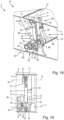
Figs. 11-17 , with a view on the actuation mechanism, - Fig. 19
- a front view of the actuation mechanism of the wing shown in
Figs. 11-17 , and - Figs. 20-21
- a detailed side view of a wing according to a third embodiment of the invention, with a view on the actuation mechanism at different stages of actuation.
-
Figs. 2-10 show anexemplary aircraft 1 according to an embodiment of the present invention. Theaircraft 1 comprises afoldable wing 3 including a fixedwing 5 mounted to a fuselage 7, and a foldablewing tip portion 9 movably mounted to the fixedwing 5. -
Figs. 2 to 10 illustrate a first embodiment of thewing 3 of theaircraft 1 shown inFig. 1 in further detail. The foldablewing tip portion 9 is mounted to the fixedwing 5 via ahinge 11 rotatable about ahinge axis 13 between anextended position 15 and a foldedposition 17. In theextended position 15 the foldablewing tip portion 9 extends as a continuous extension of the fixedwing 5 in a common plane with the fixedwing 5, wherein in the foldedposition 17 the foldablewing tip portion 9 extends upwards in order to reduce the overall span of theaircraft 1. Thehinge axis 13 extends in parallel to a chord line and in a flight direction of theaircraft 1. Thehinge 11 comprises atip hinge part 19 mounted to the foldablewing tip portion 9 and awing hinge part 21 mounted to the fixedwing 5 and engaging thetip hinge part 19 in a manner rotatable about thehinge axis 13. Thehinge axis 13 is located at the upper leading edge side of the fixedwing 5 and thetip hinge part 19 is in the form of a goose neck, so that the foldablewing tip portion 9 in the foldedposition 17 can be pivoted to a far inboard position above the upper surface of the fixedwing 5. - The
wing 3 further comprises anactuation mechanism 24 for actuating the foldablewing tip portion 9 for movement between theextended position 15 and the foldedposition 17. Theactuation mechanism 24 comprises adrive arm 27 mounted to the fixedwing 5 in a manner rotatably driven about adrive axis 29 by a motor (not shown). Specifically, thedrive arm 27 is mounted to arotating drive shaft 31 driven by the motor. Thedrive arm 27 is configured to effect movement of the foldablewing tip portion 9 between theextended position 15 and the foldedposition 17 upon rotation of thedrive arm 27 about thedrive axis 29. - The
actuation mechanism 24 comprises acatch element 33 in the form of a pin or projection mounted to thetip hinge part 19. Thedrive arm 27 and thecatch element 33 are configured such that in theextended position 15 of the foldablewing tip portion 9 upon rotation of thedrive arm 27 thedrive arm 27 contacts thecatch element 33 and upon further rotation pushes the foldablewing tip portion 9 towards the foldedposition 17. In the first embodiment shown inFigs. 2 to 10 , thedrive axis 29 is coaxial with thehinge axis 13. - As also shown in
Figs. 2 to 10 , theactuation mechanism 24 comprises alatch mechanism 35 for latching the foldablewing tip portion 9 against the fixedwing 5 in theextended position 15. Thelatch mechanism 35 can be operated by rotation of thedrive arm 27. In such a way, movement of the foldablewing tip portion 9 between theextended position 15 and the foldedposition 17 as well as latching of the foldablewing tip portion 9 in theextended position 15 can be actuated only by movement of thedrive arm 27, and thus only by a single motor. - The
latch mechanism 35 comprises awing latch part 37 mounted to the fixedwing 5, and atip latch part 39 mounted to the foldablewing tip portion 9 in a manner rotatable about alatch axis 41. Thelatch axis 41 is parallelly spaced from thedrive axis 29. Thetip latch part 39 can be brought into latching engagement with thewing latch part 37 by rotating thetip latch part 39 about thelatch axis 41 when the foldablewing tip portion 9 is in theextended position 15. Thedrive arm 27 is coupled to thetip latch part 39 via alatch link 43, such that thedrive arm 27, when rotating about thedrive axis 29, causes thetip latch part 39, through thelatch link 43, to rotate about thelatch axis 41. Thelatch link 43 is rotatably mounted to thedrive arm 27 by a rotatable joint at its one end and is rotatably mounted to thetip latch part 39 by a rotatable joint at its opposite end. Thewing latch part 37 is formed as a bolt and thetip latch part 39 is formed as a semi-circular sleeve engaging the bolt. - The
actuation mechanism 24 is configured such that thedrive arm 27 rotates about thedrive axis 29 from afirst position 45 along a firstangular range 47 to asecond position 49 and subsequently from thesecond position 49 along a secondangular range 51 to athird position 53, in the present embodiment by continuous rotation. In thefirst position 45 of thedrive arm 27 thetip latch part 39 is in a latchedposition 55 relative to thewing latch part 37. In thesecond position 49 of thedrive arm 27 thetip latch part 39 is in anunlatched position 57 relative to thewing latch part 37. When thedrive arm 27 is rotated along the firstangular range 47 from thefirst position 45 to thesecond position 49, thetip latch part 39 is rotated about thelatch axis 41 from the latchedposition 55 to theunlatched position 57. Further, in thefirst position 45 and along the firstangular range 47 thedrive arm 27 is out of contact with thecatch element 33. In thesecond position 49 thedrive arm 27 contacts thecatch element 33. When thedrive arm 27 is rotated along the secondangular range 51 from thesecond position 49 to thethird position 53, thedrive arm 27 is in continuous contact with thecatch element 33, while the foldablewing tip portion 9 is moved from theextended position 15 to the foldedposition 17. - As also shown in
Figs. 2 to 10 , theactuation mechanism 24 comprises a pull-back mechanism 59 for pulling the foldablewing tip portion 9 from the foldedposition 17 back to theextended position 15. The pull-back mechanism 59 comprises a pull-back catch 61 in the form of a pin or a projection mounted to thetip hinge part 19. The pull-back mechanism 59 further comprises a pull-back element 63 in the form of a hook mounted to thetip latch part 39 and configured for engaging the pull-back catch 61 to pull back the foldablewing tip portion 9 from the foldedposition 17 to theextended position 15 when thedrive arm 27 is rotated in a reverse direction, i.e. reverse from the direction in which thedrive arm 27 rotates to move the foldablewing tip portion 9 to the foldedposition 17. The pull-back mechanism 59 is configured such that the pull-back element 63 is engaged with the pull-back catch 61 when thetip latch part 39 is in theunlatched position 57, and the pull-back element 63 is disengaged from the pull-back catch 61 when thetip latch part 39 is in the latchedposition 55. The pull-back mechanism 59 enables theactuation mechanism 24 to bring the foldablewing tip portion 9 back to theextended position 15 in cases where the gravitational force is not sufficient to do so. - As visible in
Figs. 2 to 6 , when thedrive arm 27 is in thefirst position 45, thedrive arm 27 and thelatch link 43 are in an over-centred state, where the rotatable joint between thedrive arm 27 and thelatch link 43 is not aligned with thedrive axis 29 and the rotatable joint between thelatch link 43 and thetip latch part 39, i.e. the rotatable joint between thedrive arm 27 and thelatch link 43 does not lie on a straight line connecting thedrive axis 29 and the rotatable joint between thelatch link 43 and thetip latch part 39, but is offset from said line to a certain extent in an inboard direction, i.e. in the direction to the fuselage 7. In thefirst position 45 of thedrive arm 27 thedrive arm 27 rests against astop member 64 mounted to the fixedwing 5 and limiting rotation of thedrive arm 27 beyond thefirst position 45, i.e. before thefirst position 45, in the inboard direction. By such a configuration of thedrive arm 27 and thelatch link 43 being in an over-centred state in thefirst position 45 of thedrive arm 27 and at the same time resting against thestop member 64, a self-locking effect for thetip latch part 39 can be achieved, so that thetip latch part 39 cannot rotate out of the latchedposition 55 on its own, as this would merely push thedrive arm 27 further onto thestop member 64 which thus blocks any rotation of thetip latch part 39 out of the latchedposition 55. The only way for thetip latch part 39 to rotate out of the latchedposition 55 is being pulled by thedrive arm 27 and latch link 43 when thedrive arm 27 rotates out of thefirst position 45 towards thesecond position 49, thereby eliminating the over-centred state of thedrive arm 27 and thelatch link 43. - In
Figs. 11 to 19 a second embodiment of the invention is shown that differs from the first embodiment shown inFigs. 2 to 10 in that theactuation mechanism 24 further comprises alocking mechanism 65 for locking thetip latch part 39 and thewing latch part 37 in latching engagement with one another. Thelocking mechanism 65 can be operated by rotation of thedrive arm 27. Thelocking mechanism 65 comprises a lockingelement 67 in the form of a locking cam mounted to the fixedwing 5 in a manner rotatable about a lockingaxis 69 between a lockedposition 71 and anunlocked position 73. The lockingaxis 69 is parallelly spaced from thedrive axis 29. In the lockedposition 71 the lockingelement 67 engages thetip latch part 39, specifically a latch cam of thetip latch part 39, and thereby inhibits thetip latch part 39 from rotating out of the latchedposition 55. In theunlocked position 73 the lockingelement 67 is disengaged from thetip latch part 39 and allows rotation of thetip latch part 39 towards theunlatched position 57. - As shown in
Figs. 11 to 19 , the lockingelement 67 is moved between the lockedposition 71 and theunlocked position 73 by a lockinglinkage 75 that can be operated by rotation of thedrive arm 27 about thedrive axis 29. The lockinglinkage 75 comprises a lockingdrive arm 77, a swinginglink 79, afirst locking link 81, and asecond locking link 83. The lockingdrive arm 77 is mounted to the fixedwing 5 in a manner rotatable about thedrive axis 29 and rotationally fixed with thedrive arm 27, with respect to thedrive axis 29. In the present embodiment, the lockingdrive arm 77 extends under an angle of about 100° from thedrive arm 27. The swinginglink 79 is mounted to the fixedwing 5 in a manner rotatable about a swingingaxis 85 and having first andsecond link portions axis 85 and extending away from the swingingaxis 85 in opposite directions or at least partly opposite directions. Thefirst locking link 81 couples thefirst link portion 87 of the swinginglink 79 to the lockingdrive arm 77 by being rotatably mounted to the lockingdrive arm 77 at a first end and rotatably mounted to thefirst link portion 87 at an opposite second end of thefirst locking link 81. The second locking link 83 couples thesecond link portion 89 of the swinginglink 79 to the lockingelement 67 by being rotatably mounted to the lockingelement 67 at a first end and rotatably mounted to thesecond link portion 89 at an opposite second end of thesecond locking link 83. - The locking
element 67 and thetip latch part 39 are configured to engage in a snapping manner, when the lockingelement 67 is rotated into the lockedposition 71 and thetip latch part 39 is in the latchedposition 55 or rotated to the latchedposition 55. In the present embodiment, this is realized by the corresponding portions of the lockingelement 67 and thetip latch part 39, i.e. the locking cam and the latch cam, contacting each other and slightly deform before snapping into the lockedposition 71. This is caused by slightly eccentric contours of the latch cam and the locking cam. By such a snapping engagement of the lockingelement 67 and the tip latch part 39 a self-closing effect of thelocking mechanism 65 is achieved. - In
Figs. 20 to 21 a third embodiment of the invention is shown that differs from the first embodiment shown inFigs. 2 to 10 in that thedrive axis 29 is parallelly spaced from thehinge axis 13, instead of being coaxial with thehinge axis 13. Further, thecatch element 33 is formed as an elongate guide surface along which thedrive arm 27 rolls by aroller 91 mounted to a projecting part of thedrive arm 27, while thedrive arm 27 pushes the foldablewing tip portion 9 towards the foldedposition 17. By such an arrangement, the torque applied to the foldablewing tip portion 9 and its rotational speed during rotation from theextended position 15 to the foldedposition 17 can be tailored as required. - By the invention as described above, a
wing 3 with a very simple, compact andreliable actuation mechanism 24 is provided that allows easy assembly and maintenance.
Claims (15)
- A wing (3) for an aircraft (1), comprisinga fixed wing (5),a foldable wing tip portion (9) mounted to the fixed wing (5) via a hinge (11) rotatable about a hinge axis (13) between an extended position (15) and a folded position (17), andan actuation mechanism (24) for actuating the foldable wing tip portion (9) for movement between the extended position (15) and the folded position (17),wherein the hinge (11) comprises a tip hinge part (19) mounted to the foldable wing tip portion (9) and a wing hinge part (21) mounted to the fixed wing (5) and engaging the tip hinge part (19) in a manner rotatable about the hinge axis (13),wherein the actuation mechanism (24) comprises a drive arm (27) mounted to the fixed wing (5) in a manner rotatably driven about a drive axis (29), andwherein the drive arm (27) is configured to effect movement of the foldable wing tip portion (9) between the extended position (15) and the folded position (17) upon rotation of the drive arm (27) about the drive axis (29),characterized in thatthe actuation mechanism (24) comprises a catch element (33) mounted to the tip hinge part (19) or to the structure of the foldable wing tip portion (9), andthe drive arm (27) and the catch element (33) are configured such that in the extended position (15) of the foldable wing tip portion (9) upon rotation of the drive arm (27) the drive arm (27) contacts the catch element (33) and upon further rotation pushes the foldable wing tip portion (9) towards the folded position (17).
- The wing (3) according to claim 1, wherein the drive axis (29) is coaxial with the hinge axis (13).
- The wing (3) according to claim 1, wherein the drive axis (29) is parallelly spaced from the hinge axis (13).
- The wing (3) according to any of claims 1 to 3, wherein the actuation mechanism (24) comprises a latch mechanism (35) for latching the foldable wing tip portion (9) in the extended position (15), and
wherein the latch mechanism (35) can be operated by rotation of the drive arm (27). - The wing (3) according to claim 4, wherein the latch mechanism comprises (35) a wing latch part (37) mounted to the fixed wing (5), and a tip latch part (39) mounted to the foldable wing tip portion (9) in a manner rotatable about a latch axis (41),wherein the tip latch part (39) can be brought into latching engagement with the wing latch part (37) by rotating the tip latch part (39) about the latch axis (41) when the foldable wing tip portion (9) is in the extended position (15),wherein the drive arm (27) is coupled to the tip latch part (39) via a latch link (43), such that the drive arm (27) when rotating about the drive axis (29) causes the tip latch part (39), through the latch link (43), to rotate about the latch axis (41).
- The wing (3) according to claim 5, wherein the wing latch part (37) is formed as a bolt and the tip latch part (39) is formed as a semi-circular sleeve engaging the bolt.
- The wing (3) according to claim 5 or 6, wherein the actuation mechanism (24) is configured such that the drive arm (27) rotates about the drive axis (29) from a first position (45) along a first angular range (47) to a second position (49) and subsequently from the second position (49) along a second angular range (51) to a third position (53),wherein in the first position (45) of the drive arm (27) the tip latch part (39) is in a latched position (55) relative to the wing latch part (37),wherein in the second position (49) of the drive arm (27) the tip latch part (39) is in an unlatched position (57) relative to the wing latch part (37),wherein, when the drive arm (27) is rotated along the first angular range (47) from the first position (45) to the second position (49), the tip latch part (39) is rotated about the latch axis (41) from the latched position (55) to the unlatched position (57),wherein in the first position (45) and along the first angular range (47) the drive arm (27) is out of contact with the catch element (33),wherein in or near the second position (49) the drive arm (27) contacts the catch element (33), andwherein, when the drive arm (27) is rotated along the second angular range (51) from the second position (49) to the third position (53), the drive arm (27) is in contact with the catch element (33), while the foldable wing tip portion (9) is moved from the extended position (15) to the folded position (17).
- The wing (3) according to any of claims 5 to 7, wherein the actuation mechanism (24) comprises a pull-back mechanism (59) for pulling the foldable wing tip portion (9) from the folded position (17) back to the extended position (15),wherein the pull-back mechanism (59) comprises a pull-back catch (61) mounted to the tip hinge part (19) or to the structure of the foldable wing tip portion (9), andwherein the pull-back mechanism (59) comprises a pull-back element (63) mounted to the tip latch part (39), to the latch link (43), or to the drive arm (27) and configured for engaging the pull-back catch (61) to pull back the foldable wing tip portion (9) from the folded position (17) to the extended position (15) when the drive arm (27) is rotated in a reverse direction, andwherein the pull-back mechanism (59) is configured such that the pull-back element (63) is engaged with the pull-back catch (61) when the tip latch part (39) is in the unlatched position (57), and the pull-back element (63) is disengaged with the pull-back catch (61) when the tip latch part (39) is in the latched position (55).
- The wing (3) according to any of claims 5 to 8, wherein the actuation mechanism (24) comprises a locking mechanism (65) for locking the tip latch part (39) and the wing latch part (37) in latching engagement with one another, and
wherein the locking mechanism (65) can be operated by rotation of the drive arm (27). - The wing (3) according to claim 9, wherein the locking mechanism (65) comprises a locking element (67) mounted to the fixed wing (5) in a manner rotatable about a locking axis (69) between a locked position (71) and an unlocked position (73),wherein in the locked position (71) the locking element (67) engages the tip latch part (39) and thereby inhibits the tip latch part (39) from rotating out of the latched position (55), andwherein in the unlocked position (73) the locking element (67) is disengaged from the tip latch part (39) and allows rotation of the tip latch part (39) towards the unlatched position (57).
- The wing (3) according to claim 10, wherein the locking element (67) is moved between the locked position (71) and the unlocked position (73) by a locking linkage (75) that can be operated by rotation of the drive arm (27) about the drive axis (29).
- The wing (3) according to claim 11, wherein the locking linkage (75) comprisesa locking drive arm (77) mounted to the fixed wing (5) in a manner rotatable about the drive axis (29) and rotationally fixed with the drive arm (27),a swinging link (79) mounted to the fixed wing (5) in a manner rotatable about a swinging axis (85) and having first and second link portions (87, 89) on opposite sides of the swinging axis (85),a first locking link (81) coupling the first link portion (87) of the swinging link (79) to the locking drive arm (77), anda second locking link (83) coupling the second link portion (89) of the swinging link (79) to the locking element (67).
- The wing (3) according to any of claims 10 to 12, wherein the locking element (67) and the tip latch part (39) are configured to engage in a snapping manner, when the locking element (67) is rotated into the locked position (71).
- An actuation mechanism (24) for the wing (3) according to any of claims 1 to 13, comprisinga drive arm (27) configured for being mounted to the fixed wing (5) in a manner rotatably driven about a drive axis (29),wherein the drive arm (27) is configured to effect movement of the foldable wing tip portion (9) between the extended position (15) and the folded position (17) upon rotation of the drive arm (27) about the drive axis (29),characterized in thatthe drive arm (27) is configured such that in the extended position (15) of the foldable wing tip portion (9) upon rotation of the drive arm (27) the drive arm (27) contacts the catch element (33) and upon further rotation pushes the foldable wing tip portion (9) towards the folded position (17).
- An aircraft (1) comprising the wing (3) according to any of claims 1 to 13, or comprising the actuation mechanism (24) according to claim 14.
Priority Applications (3)
| Application Number | Priority Date | Filing Date | Title |
|---|---|---|---|
| EP22154391.1A EP4219295A1 (en) | 2022-01-31 | 2022-01-31 | Wing for an aircraft |
| US18/103,047 US20230365248A1 (en) | 2022-01-31 | 2023-01-30 | Wing for an aircraft |
| CN202310053631.9A CN116513447A (en) | 2022-01-31 | 2023-01-31 | Wing for an aircraft, actuating mechanism for a wing and aircraft |
Applications Claiming Priority (1)
| Application Number | Priority Date | Filing Date | Title |
|---|---|---|---|
| EP22154391.1A EP4219295A1 (en) | 2022-01-31 | 2022-01-31 | Wing for an aircraft |
Publications (1)
| Publication Number | Publication Date |
|---|---|
| EP4219295A1 true EP4219295A1 (en) | 2023-08-02 |
Family
ID=80119306
Family Applications (1)
| Application Number | Title | Priority Date | Filing Date |
|---|---|---|---|
| EP22154391.1A Pending EP4219295A1 (en) | 2022-01-31 | 2022-01-31 | Wing for an aircraft |
Country Status (3)
| Country | Link |
|---|---|
| US (1) | US20230365248A1 (en) |
| EP (1) | EP4219295A1 (en) |
| CN (1) | CN116513447A (en) |
Citations (3)
| Publication number | Priority date | Publication date | Assignee | Title |
|---|---|---|---|---|
| EP3059161A1 (en) * | 2015-02-17 | 2016-08-24 | Airbus Operations Limited | An arrangement for moving a wing tip device between a flight configuration and a ground configuration |
| US20190322351A1 (en) * | 2018-04-24 | 2019-10-24 | Airbus Operations Gmbh | Wing for an aircraft |
| US20190337605A1 (en) * | 2018-05-03 | 2019-11-07 | Airbus Operations Gmbh | Wing for an aircraft |
-
2022
- 2022-01-31 EP EP22154391.1A patent/EP4219295A1/en active Pending
-
2023
- 2023-01-30 US US18/103,047 patent/US20230365248A1/en active Pending
- 2023-01-31 CN CN202310053631.9A patent/CN116513447A/en active Pending
Patent Citations (3)
| Publication number | Priority date | Publication date | Assignee | Title |
|---|---|---|---|---|
| EP3059161A1 (en) * | 2015-02-17 | 2016-08-24 | Airbus Operations Limited | An arrangement for moving a wing tip device between a flight configuration and a ground configuration |
| US20190322351A1 (en) * | 2018-04-24 | 2019-10-24 | Airbus Operations Gmbh | Wing for an aircraft |
| US20190337605A1 (en) * | 2018-05-03 | 2019-11-07 | Airbus Operations Gmbh | Wing for an aircraft |
Also Published As
| Publication number | Publication date |
|---|---|
| US20230365248A1 (en) | 2023-11-16 |
| CN116513447A (en) | 2023-08-01 |
Similar Documents
| Publication | Publication Date | Title |
|---|---|---|
| RU2486103C2 (en) | Device to open and close aircraft landing gear well (versions) and landing gear well flap mechanism | |
| US10214278B2 (en) | Aircraft comprising a foldable aerodynamic structure and an articulation mechanism for a foldable aerodynamic structure | |
| JP2902104B2 (en) | Casement operation device | |
| CA1061816A (en) | Door operator with locking mechanism | |
| US7942185B2 (en) | Folding leaf gate | |
| CN110435872B (en) | Wing of aircraft | |
| CN102140873B (en) | Locking device, aircraft equipped with the device and extraction method implemented by the device | |
| US20130299633A1 (en) | Landing gear for an aircraft | |
| PT1541517E (en) | Device on an elevator car for temporaly coupling a car door panel with a landing door panel and for actuating a car door locking mechanism | |
| US6067869A (en) | Actuating assembly for motor-vehicle door latch | |
| CN105565126A (en) | Synchronous door knife integrated with car door lock and synchronous door knife system | |
| US20090079234A1 (en) | Adjustment Device for a Sliding Roof Cover on a Vehicle | |
| EP2274201A1 (en) | Spoiler deployment mechanism | |
| EP4219295A1 (en) | Wing for an aircraft | |
| CN111284680A (en) | System for operating an aircraft door | |
| US20190283867A1 (en) | Method of driving an aircraft undercarriage between a deployed position and a retracted position | |
| CN112078444B (en) | Slide rail easily enters unblock retaining mechanism | |
| EP0484170B1 (en) | Door coupling device | |
| EP3922546A1 (en) | Passenger door lock for drop-down style doors on an aircraft | |
| KR102323377B1 (en) | Manipulators for access members, access members comprising manipulators, systems and methods | |
| EP3211165A1 (en) | Checking device for a tilt-and-turn wing of a window or a door for motor-driven tilting and manual turning and tilting | |
| JPH09228707A (en) | Lock device | |
| RU2396410C1 (en) | Locking device for gates | |
| RU2406812C2 (en) | Lever mechanism for rod fittings | |
| CN214003754U (en) | Single-knife movable asynchronous door knife device |
Legal Events
| Date | Code | Title | Description |
|---|---|---|---|
| PUAI | Public reference made under article 153(3) epc to a published international application that has entered the european phase |
Free format text: ORIGINAL CODE: 0009012 |
|
| STAA | Information on the status of an ep patent application or granted ep patent |
Free format text: STATUS: THE APPLICATION HAS BEEN PUBLISHED |
|
| AK | Designated contracting states |
Kind code of ref document: A1 Designated state(s): AL AT BE BG CH CY CZ DE DK EE ES FI FR GB GR HR HU IE IS IT LI LT LU LV MC MK MT NL NO PL PT RO RS SE SI SK SM TR |
|
| STAA | Information on the status of an ep patent application or granted ep patent |
Free format text: STATUS: REQUEST FOR EXAMINATION WAS MADE |
|
| 17P | Request for examination filed |
Effective date: 20240202 |
|
| RBV | Designated contracting states (corrected) |
Designated state(s): AL AT BE BG CH CY CZ DE DK EE ES FI FR GB GR HR HU IE IS IT LI LT LU LV MC MK MT NL NO PL PT RO RS SE SI SK SM TR |