EP4219041A1 - Apparatus and method for twisting wires - Google Patents
Apparatus and method for twisting wires Download PDFInfo
- Publication number
- EP4219041A1 EP4219041A1 EP22153936.4A EP22153936A EP4219041A1 EP 4219041 A1 EP4219041 A1 EP 4219041A1 EP 22153936 A EP22153936 A EP 22153936A EP 4219041 A1 EP4219041 A1 EP 4219041A1
- Authority
- EP
- European Patent Office
- Prior art keywords
- holder
- twisting
- twisting unit
- motion
- unit
- Prior art date
- Legal status (The legal status is an assumption and is not a legal conclusion. Google has not performed a legal analysis and makes no representation as to the accuracy of the status listed.)
- Granted
Links
Images

Classifications
-
- B—PERFORMING OPERATIONS; TRANSPORTING
- B21—MECHANICAL METAL-WORKING WITHOUT ESSENTIALLY REMOVING MATERIAL; PUNCHING METAL
- B21F—WORKING OR PROCESSING OF METAL WIRE
- B21F15/00—Connecting wire to wire or other metallic material or objects; Connecting parts by means of wire
- B21F15/02—Connecting wire to wire or other metallic material or objects; Connecting parts by means of wire wire with wire
- B21F15/04—Connecting wire to wire or other metallic material or objects; Connecting parts by means of wire wire with wire without additional connecting elements or material, e.g. by twisting
-
- B—PERFORMING OPERATIONS; TRANSPORTING
- B21—MECHANICAL METAL-WORKING WITHOUT ESSENTIALLY REMOVING MATERIAL; PUNCHING METAL
- B21F—WORKING OR PROCESSING OF METAL WIRE
- B21F7/00—Twisting wire; Twisting wire together
-
- H—ELECTRICITY
- H01—ELECTRIC ELEMENTS
- H01B—CABLES; CONDUCTORS; INSULATORS; SELECTION OF MATERIALS FOR THEIR CONDUCTIVE, INSULATING OR DIELECTRIC PROPERTIES
- H01B13/00—Apparatus or processes specially adapted for manufacturing conductors or cables
- H01B13/02—Stranding-up
- H01B13/0207—Details; Auxiliary devices
-
- H—ELECTRICITY
- H01—ELECTRIC ELEMENTS
- H01B—CABLES; CONDUCTORS; INSULATORS; SELECTION OF MATERIALS FOR THEIR CONDUCTIVE, INSULATING OR DIELECTRIC PROPERTIES
- H01B13/00—Apparatus or processes specially adapted for manufacturing conductors or cables
- H01B13/02—Stranding-up
- H01B13/0235—Stranding-up by a twisting device situated between a pay-off device and a take-up device
-
- H—ELECTRICITY
- H01—ELECTRIC ELEMENTS
- H01B—CABLES; CONDUCTORS; INSULATORS; SELECTION OF MATERIALS FOR THEIR CONDUCTIVE, INSULATING OR DIELECTRIC PROPERTIES
- H01B7/00—Insulated conductors or cables characterised by their form
- H01B7/0045—Cable-harnesses
Definitions
- the present invention relates to an apparatus and a method for twisting an element, in particular a wire or multiple wires.
- wires or part of wires or pairs of wires are typically twisted, which improves the connection among different parts. For instance, twisting helps to alleviate exterior electromagnetic interferences, which improves electromagnetic compatibility.
- Central twisting machines typically include a securing mechanism configured to secure ends of the wires, e.g. a first and a second wire to be twisted.
- the first wire is arranged parallel to the second wire along a longitudinal axis.
- the machine also includes a gripping mechanism to grip central portions of the first and second wires such that inner surfaces of the central portions of the first and second wires are in contact with one another, and a rotating mechanism configured to rotate the gripping mechanism, thereby twisting the first and second wires about one another.
- these machines have several deficiencies, such as a height limitation of the twisting head, e.g. a range in which it is moved up and down and a length limitation of the wire to twist. Furthermore, these machines are complex and do not provide for a balanced force of wires, while the wires are twisted.
- a high demand pertains to provide for an improved apparatus and improved method for twisting a wire, parts of a wire or wires or several wires.
- a first embodiment is directed to an apparatus for twisting an elongate element such as a wire or cable, comprising a) a first holder adapted to hold a first portion of the element; b) a second holder adapted to hold a second portion of the element; c) a twisting unit adapted to twist the element at a third portion between the first and the second portion; wherein the twisting unit and the second holder are adapted to be movable relative to the first holder in the same direction.
- wire as used herein is used in its broadest sense and covers all kind of wires, cables, cords, leads, etc. that are used for transmitting electrical power and/or signals.
- a holder may be an arrangement than can hold, grip or secure an element, when the element is arranged or used in the apparatus.
- a twisting unit may be a mechanism to twist the element.
- the element is not part of the apparatus, however, when the apparatus is used or is in operation to twist an element, an element is usually placed in at least a part of the apparatus.
- the element maybe a wire, cable, a lead or strand or the like that may be twisted.
- the element may be folded prior to twisting to form two or more substantially parallel parts of the element that may be twisted about one another, and which may be cut prior or after twisting.
- the element may also comprise one or more elements that may be twisted about one another.
- Twisting of the element may be understood as a rotation along an elongate axis of the element.
- twisting of the element may comprise twisting two or more individual parts of the element about one another, e.g. by folding the element prior to twisting.
- twisting the element may comprise twisting two or more elements, such as two or more wires, about one another.
- the twisting unit may advantageously be adapted to interact with a central portion of the element, when the element is arranged or used in the apparatus for twisting the element.
- the twisting unit may be arranged substantially in the middle between the second holder and the first holder.
- This apparatus is adapted to twist an element and may beneficially compensate for a length reduction of a twisted element, which may occur during twisting the element. Further, the apparatus may advantageously not be limited to any vertical motions of parts comprised by the apparatus.
- the forces acting on the element may be improved during twisting due to the twisting unit and the second holder being adapted to be movable relative to the first holder in the same direction.
- the same direction of the motion of the second holder and the twisting unit may comprise the same longitudinal and/or the same horizontal direction.
- the extent of motion of the second holder and the twisting unit in the same direction may be different to one another.
- the twisting unit and the second holder move towards the first holder during twisting an element to beneficially compensate for a length reduction.
- the twisting may be more stable.
- the apparatus according to the present invention may facilitate a more efficient and ergonomic unloading of the element. Further, the unloading of the element may be easily automated by the apparatus. The apparatus thus beneficially allows to compensate for a length reduction during twisting the element. The twisting force, torsion and tension force of the element are improved.
- the second holder and the twisting unit of the apparatus are adapted such that the motion of the second holder is synchronized with the motion of the twisting unit.
- a synchronization of the motion of the second holder and the motion of the twisting unit may comprise that a motion of the twisting unit entails a motion of the second holder or vice versa.
- the motions must not necessarily be the same with respect to an amount of velocity. These motions may be in the same, preferably horizontal and longitudinal direction. These motions may allow for compensating a length reduction during twisting.
- the motion of the second holder and the motion of the twisting unit are substantially in a translational direction, preferably substantially parallel to a longitudinal axis of the element when arranged in the apparatus.
- a translational direction of motion may be understood as a motion in one axis. This motion may be easy to provide for and thus simplifies the apparatus.
- the second holder and the twisting unit of the apparatus are adapted to perform substantially horizontal motions in a direction towards the first holder and away from the first holder.
- a horizontal motion may be understood as perpendicular to the gravity. Thus, the motion is not required to be against gravity, which simplifies the motion.
- This motion may be performed during twisting an element. Reducing a distance of the second holder and the twisting unit to the first holder by way of a direction of motion towards the first holder facilitates a length compensation of an element during twisting of the element.
- the motion of the second holder and the motion of the twisting unit are coupled by a gear mechanism, defining a relationship of the motion of the second holder and the motion of the twisting unit.
- a gear mechanism may comprise a gear with a gear ratio.
- the gear mechanism may have one or more stages.
- the gear ratio may translate a motion of the twisting unit to a motion of the second holder or vice versa.
- the second holder and the twisting unit are adapted such that a translational velocity of the motion of the second holder is greater than a translational velocity of the motion of the twisting unit by a factor of 1.5 to 2.5 if L2 is greater than L1 by a factor of 1.5 to 2.5, preferably by a factor of 1.8 to 2.2 if L2 is greater than L1 by a factor of 1.8 to 2.2, wherein L2 is a distance of the second holder to the first holder and L1 is a distance of the twisting unit to the first holder.
- the ratio of the translational velocity of the second holder and the twisting unit may beneficially depend on the distances L2 and L1. For example, if L2 is twice the value of Li, then the translational velocity of the second holder may be twice the value of the translational velocity of the twisting unit. In another example, if L2 is 2.1 the value of Li, then the translational velocity of the second holder may be 2.1 the value of the translational velocity of the twisting unit. This may advantageously provide for an improved length compensation during twisting an element.
- the second holder and the twisting unit are adapted such that a translational velocity of the second holder and a translational velocity of the twisting unit are coupled to a rotational twisting velocity of the twisting unit.
- Twisting an element may comprise a rotation of at least part of the twisting unit comprised by the apparatus.
- This rotation may be described by a rotational twisting velocity.
- a rotational twisting velocity of the twisting unit is increased, a translational velocity of the second holder and a translational velocity of the twisting unit may be beneficially increased as well to allow for length compensation of an element during twisting the element. Therefore, coupling the rotational twisting velocity of the twisting unit to the translational velocity of the second holder and to the translational velocity of the twisting unit may be advantageous.
- a rotational twisting velocity may also be described by an angular velocity.
- the first holder is adapted to hold the first portion of the element in a removably fixed manner
- the second holder is adapted to hold the second portion of the element in a removably fixed manner, when the element is arranged in the apparatus.
- adapted to hold the first or second portion may comprise that the element is gripped or secured, when the element is arranged or used in the apparatus.
- twisting of the element in proximity of the first portion and the second portion of the element may be substantially prevented. Twisting of the element in the remaining portions of the element may be facilitated.
- the twisting unit is adapted to interact with the element, when arranged in the apparatus, at a portion between 20%-80%, preferably 30%-70%, more preferably 40%-60%, most preferably between 45%-55% of a distance of the first holder and the second holder.
- the twisting unit is preferably adapted such that it interacts with an element at a central position of the element when the element is arranged in or used in the apparatus.
- a central position may be understood with respect to the first and the second holder, e.g. most preferably a central position may be a position at 50% of the distance of the first holder and the second holder.
- the second holder is adapted to establish a tension force on the element to maintain a substantially straight alignment.
- a tension force may be understood as a force that substantially provides for an elongate and horizontal shape of the element when the element is arranged or used in the apparatus for twisting the element. This may provide for a substantially straight alignment of an element, when used in the apparatus.
- a substantially small amount of sagging of the element may be allowed. This sagging may be understood as a portion of the element between the first holder and the twisting unit or between the twisting unit and the second holder may be slightly lower with respect to a horizontal line that passes through the first portion of the element, which may be hold by the first holder and the second portion of the element, which may be hold by the second holder.
- the twisting unit is adapted to twist the element, when arranged in the apparatus, at the third portion causing twisting substantially the overall element, when the element is arranged in the apparatus.
- Another embodiment of the invention is directed to a method for twisting an elongate element such as a wire or cable, comprising: a) providing an elongate element; b) holding a first portion of the element with a first holder; c) holding a second portion of the element with a second holder; and d) twisting the element at a third portion between the first and the second portion with a twisting unit, wherein the twisting unit and the second holder are moved relative to the first holder in the same direction, preferably in the same translational direction.
- the second holder and the twisting unit are moved substantially horizontally towards the first holder while twisting the element, optionally wherein a translational velocity of the second holder and a translational velocity of the twisting unit are coupled to a rotational twisting velocity of the twisting unit while twisting the element.
- providing the elongate element comprises:
- the element provided in the method and/or used in the apparatus may be a wire, cable, a lead or strand or the like that may be twisted.
- the element may be folded prior to twisting to form two or more substantially parallel parts of the element that may be twisted about one another, and which may be cut prior or after twisting.
- the element may also comprise one or more elements that may be twisted about one another. Twisting of the element maybe understood as a rotation along an elongate axis of the element. In one example, twisting of the element may comprise twisting two or more individual parts of the element about one another, e.g. by folding the element prior to twisting. In another example, twisting the element may comprise twisting two or more elements, such as two or more wires, about one another.
- the method may advantageously comprise steps to operate the apparatus as described above.
- Another embodiment of the invention is directed to a twisted element manufactured according to the method described above.
- the element that can be used in an apparatus and the method according to an embodiment of the invention may have a cross section between 0.1-20.0 mm 2 , more preferably between 0.5-15.0 mm 2 , even more preferably between 1.0-10.0 mm 2 , even further preferably between 2.0-8.0 mm 2 , most preferably between 4.0-6.0 mm 2 .
- the element that can be used in an apparatus and the method according to an embodiment of the invention may have a length before twisting between 2000-6000 mm, preferably between 2500-5000 mm, more preferably between 3000-4000 mm, most preferably between 3200-3800 mm.
- the element may also be deformable, for instance it may be deformable by user interaction.
- Fig. 1 illustrates a schematic view of an apparatus 1, according to an embodiment of the invention, in a first state.
- the apparatus 1 comprises a first holder 10, a second holder 20 and a twisting unit 30.
- an element 50 is placed in the apparatus 1.
- the element 50 is generally not part of the apparatus 1. However, when the apparatus 1 is used, typically an element 50 is placed in the apparatus 1.
- the element 50 may be a wire 50, for instance a single wire folded such that it forms two substantially parallel parts of the wire.
- the wire may be folded multiple times to form multiple substantially parallel parts of the wire.
- the folded wire maybe cut prior or after it is twisted using the apparatus 1.
- the element 50 may also be one or more individual wires, forming substantially parallel wires next to each other.
- the first holder 10 is adapted to hold a first portion of the element.
- the second holder 20 is adapted to hold a second portion of the element 50.
- the holders 10, 20 can be opened for receiving a portion of the element.
- the holders 10, 20 can also be closed for holding and substantially fixing a portion of the element.
- the twisting unit 30 is adapted to twist the element at a third portion of the element.
- the twisting unit 30 interacts with the element between the second holder 20 and the first holder 10.
- the twisting unit 30 interacts with the element at half a length of L2, wherein L2 is a distance of the second holder 20 to the first holder 10.
- the first state of the apparatus may represent a state, which is prior to twisting the element with the twisting unit or it may be a state in proximity to start twisting the element with the twisting unit.
- Fig. 2 illustrates apparatus 1 in a second state.
- the second state may represent a state, which is during or after twisting the element with the twisting unit.
- the second holder 20 may have a velocity, which is greater than the velocity of the twisting unit 30 by a factor of 2, wherein both, the second holder 20 and the twisting unit 30 move towards the first holder 10.
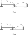
- Fig. 3 illustrates details of the moving mechanism of apparatus 1 in the first state.
- the apparatus 1 comprises a gear mechanism 35. This gear mechanism provides for a relationship of the translational velocities of the twisting unit 30 and the second holder 20, when the apparatus is in use or when the apparatus is operating.
- Fig. 4 shows the gear mechanism 35 in the second state.
- the second holder 20 and the twisting unit 30 have moved towards the first holder 10 in a substantially horizontally and translational direction. Twisting the element is provided by means of a rotational twisting velocity of the twisting unit.
- the substantially horizontal and translational motions of the second holder 20 and the twisting unit 30 are coupled to the rotational twisting velocity of the twisting unit 30. For instance, if the apparatus is in operation and the rotational twisting velocity is increased, the translational motions of the second holder 20 and the twisting unit 30 may also be increased.
- This apparatus allows to twist an element or one or more elements, wherein the apparatus is not limited to length restrictions of the element. This generally allows to twist elements with a high length. Further, the apparatus is not limited to any vertical motions of parts comprised by the apparatus. The forces acting on the element are improved during twisting; thus, the twisting is more stable. In particular, compared to vertical motions of twisting units for a length compensation of an element during twisting, as suggested in the prior art, the apparatus according to the present invention allows for a more efficient and ergonomic unloading of the element. Further, the unloading of the element can be easily automated. The apparatus thus beneficially allows to compensate for a length reduction during twisting the element. The apparatus may be applied for twisting of several wires or lead types, e.g. speakers and CAN/CAN FD applications. The advantages of the apparatus may equally apply to the method as described herein.
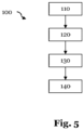
- Fig. 5 illustrates a flow chart of a method 100, according to an embodiment of the invention.
- the method 100 comprises the step of providing 110 an element.
- the method 100 further comprises the step of holding 120 a first portion of the element with a first holder.
- the method 100 comprises the step of holding 130 a second portion of the element with a second holder.
- the method also comprises the step of twisting 140 the element at a third portion between the first and the second portion with a twisting unit. During twisting, the twisting unit and the second holder are moved relative to the first holder in the same direction, preferably in a same translational direction.
Landscapes
- Engineering & Computer Science (AREA)
- Mechanical Engineering (AREA)
- Manufacturing & Machinery (AREA)
- Wire Processing (AREA)
- Investigating Strength Of Materials By Application Of Mechanical Stress (AREA)
Abstract
Description
- The present invention relates to an apparatus and a method for twisting an element, in particular a wire or multiple wires.
- Due to the ongoing industrialization and automatization, more cables, wires or the like are required to facilitate communicating connections among different parts, e.g. to electrically connect different parts. For this communication, wires or part of wires or pairs of wires are typically twisted, which improves the connection among different parts. For instance, twisting helps to alleviate exterior electromagnetic interferences, which improves electromagnetic compatibility.
- Ongoing production process automatization strategies demand for an automatization to produce twisted wires. This can be done for instance on central twisting machines.
- Central twisting machines are known and typically include a securing mechanism configured to secure ends of the wires, e.g. a first and a second wire to be twisted. The first wire is arranged parallel to the second wire along a longitudinal axis. The machine also includes a gripping mechanism to grip central portions of the first and second wires such that inner surfaces of the central portions of the first and second wires are in contact with one another, and a rotating mechanism configured to rotate the gripping mechanism, thereby twisting the first and second wires about one another.
- This poses a problem since the wires' length is shortened when the wires are twisted.
- Prior art documents
US 2021020337 A1 andUS 10946434 B2 - However, these machines have several deficiencies, such as a height limitation of the twisting head, e.g. a range in which it is moved up and down and a length limitation of the wire to twist. Furthermore, these machines are complex and do not provide for a balanced force of wires, while the wires are twisted.
- Accordingly, a high demand pertains to provide for an improved apparatus and improved method for twisting a wire, parts of a wire or wires or several wires.
- It is thus an object of the present invention to overcome some or all of the deficiencies of the prior art. In particular, it is an object of the invention to provide for an improved apparatus for twisting a wire, parts of a wire or wires or several wires. It is a further object to provide an improved method for twisting a wire, parts of a wire or wires or several wires. The apparatus and method should be simplified and cost-effective.
- These objects are at least partially achieved by the independent claims. Preferred aspects are subject of the dependent claims, and the skilled person finds hints for other suitable aspects of the present invention through the overall disclosure of the present application.
- A first embodiment is directed to an apparatus for twisting an elongate element such as a wire or cable, comprising a) a first holder adapted to hold a first portion of the element; b) a second holder adapted to hold a second portion of the element; c) a twisting unit adapted to twist the element at a third portion between the first and the second portion; wherein the twisting unit and the second holder are adapted to be movable relative to the first holder in the same direction. The term wire as used herein is used in its broadest sense and covers all kind of wires, cables, cords, leads, etc. that are used for transmitting electrical power and/or signals.
- A holder may be an arrangement than can hold, grip or secure an element, when the element is arranged or used in the apparatus. A twisting unit may be a mechanism to twist the element. Generally, the element is not part of the apparatus, however, when the apparatus is used or is in operation to twist an element, an element is usually placed in at least a part of the apparatus. The element maybe a wire, cable, a lead or strand or the like that may be twisted. The element may be folded prior to twisting to form two or more substantially parallel parts of the element that may be twisted about one another, and which may be cut prior or after twisting. The element may also comprise one or more elements that may be twisted about one another. Twisting of the element may be understood as a rotation along an elongate axis of the element. In one example, twisting of the element may comprise twisting two or more individual parts of the element about one another, e.g. by folding the element prior to twisting. In another example, twisting the element may comprise twisting two or more elements, such as two or more wires, about one another.
- The twisting unit may advantageously be adapted to interact with a central portion of the element, when the element is arranged or used in the apparatus for twisting the element. For example, the twisting unit may be arranged substantially in the middle between the second holder and the first holder.
- This apparatus is adapted to twist an element and may beneficially compensate for a length reduction of a twisted element, which may occur during twisting the element. Further, the apparatus may advantageously not be limited to any vertical motions of parts comprised by the apparatus. The forces acting on the element may be improved during twisting due to the twisting unit and the second holder being adapted to be movable relative to the first holder in the same direction. The same direction of the motion of the second holder and the twisting unit may comprise the same longitudinal and/or the same horizontal direction. The extent of motion of the second holder and the twisting unit in the same direction may be different to one another. In one example, the twisting unit and the second holder move towards the first holder during twisting an element to beneficially compensate for a length reduction. Thus, the twisting may be more stable. In particular, compared to vertical motions of twisting units for a length compensation of an element during twisting, as suggested in the prior art, the apparatus according to the present invention may facilitate a more efficient and ergonomic unloading of the element. Further, the unloading of the element may be easily automated by the apparatus. The apparatus thus beneficially allows to compensate for a length reduction during twisting the element. The twisting force, torsion and tension force of the element are improved.
- Preferably, the second holder and the twisting unit of the apparatus are adapted such that the motion of the second holder is synchronized with the motion of the twisting unit.
- A synchronization of the motion of the second holder and the motion of the twisting unit may comprise that a motion of the twisting unit entails a motion of the second holder or vice versa. The motions must not necessarily be the same with respect to an amount of velocity. These motions may be in the same, preferably horizontal and longitudinal direction. These motions may allow for compensating a length reduction during twisting.
- Further preferably, in the apparatus, the motion of the second holder and the motion of the twisting unit are substantially in a translational direction, preferably substantially parallel to a longitudinal axis of the element when arranged in the apparatus.
- A translational direction of motion may be understood as a motion in one axis. This motion may be easy to provide for and thus simplifies the apparatus.
- In another preferred embodiment, the second holder and the twisting unit of the apparatus are adapted to perform substantially horizontal motions in a direction towards the first holder and away from the first holder.
- A horizontal motion may be understood as perpendicular to the gravity. Thus, the motion is not required to be against gravity, which simplifies the motion. This motion may be performed during twisting an element. Reducing a distance of the second holder and the twisting unit to the first holder by way of a direction of motion towards the first holder facilitates a length compensation of an element during twisting of the element.
- Preferably, in the apparatus, the motion of the second holder and the motion of the twisting unit are coupled by a gear mechanism, defining a relationship of the motion of the second holder and the motion of the twisting unit.
- A gear mechanism may comprise a gear with a gear ratio. The gear mechanism may have one or more stages. The gear ratio may translate a motion of the twisting unit to a motion of the second holder or vice versa.
- Further preferably, in the apparatus, the second holder and the twisting unit are adapted such that a translational velocity of the motion of the second holder is greater than a translational velocity of the motion of the twisting unit by a factor of 1.5 to 2.5 if L2 is greater than L1 by a factor of 1.5 to 2.5, preferably by a factor of 1.8 to 2.2 if L2 is greater than L1 by a factor of 1.8 to 2.2, wherein L2 is a distance of the second holder to the first holder and L1 is a distance of the twisting unit to the first holder.
- The ratio of the translational velocity of the second holder and the twisting unit may beneficially depend on the distances L2 and L1. For example, if L2 is twice the value of Li, then the translational velocity of the second holder may be twice the value of the translational velocity of the twisting unit. In another example, if L2 is 2.1 the value of Li, then the translational velocity of the second holder may be 2.1 the value of the translational velocity of the twisting unit. This may advantageously provide for an improved length compensation during twisting an element.
- Preferably, in the apparatus, the second holder and the twisting unit are adapted such that a translational velocity of the second holder and a translational velocity of the twisting unit are coupled to a rotational twisting velocity of the twisting unit.
- Twisting an element may comprise a rotation of at least part of the twisting unit comprised by the apparatus. This rotation may be described by a rotational twisting velocity. For example, if the rotational twisting velocity of the twisting unit is increased, a translational velocity of the second holder and a translational velocity of the twisting unit may be beneficially increased as well to allow for length compensation of an element during twisting the element. Therefore, coupling the rotational twisting velocity of the twisting unit to the translational velocity of the second holder and to the translational velocity of the twisting unit may be advantageous. A rotational twisting velocity may also be described by an angular velocity.
- Further preferably, in the apparatus, the first holder is adapted to hold the first portion of the element in a removably fixed manner, and the second holder is adapted to hold the second portion of the element in a removably fixed manner, when the element is arranged in the apparatus.
- For example, adapted to hold the first or second portion may comprise that the element is gripped or secured, when the element is arranged or used in the apparatus. Thus, twisting of the element in proximity of the first portion and the second portion of the element may be substantially prevented. Twisting of the element in the remaining portions of the element may be facilitated.
- Preferably, in the apparatus, the twisting unit is adapted to interact with the element, when arranged in the apparatus, at a portion between 20%-80%, preferably 30%-70%, more preferably 40%-60%, most preferably between 45%-55% of a distance of the first holder and the second holder.
- The twisting unit is preferably adapted such that it interacts with an element at a central position of the element when the element is arranged in or used in the apparatus. A central position may be understood with respect to the first and the second holder, e.g. most preferably a central position may be a position at 50% of the distance of the first holder and the second holder.
- Further preferably, in the apparatus, the second holder is adapted to establish a tension force on the element to maintain a substantially straight alignment.
- A tension force may be understood as a force that substantially provides for an elongate and horizontal shape of the element when the element is arranged or used in the apparatus for twisting the element. This may provide for a substantially straight alignment of an element, when used in the apparatus. During operation of the apparatus, a substantially small amount of sagging of the element may be allowed. This sagging may be understood as a portion of the element between the first holder and the twisting unit or between the twisting unit and the second holder may be slightly lower with respect to a horizontal line that passes through the first portion of the element, which may be hold by the first holder and the second portion of the element, which may be hold by the second holder.
- Preferably, in the apparatus, the twisting unit is adapted to twist the element, when arranged in the apparatus, at the third portion causing twisting substantially the overall element, when the element is arranged in the apparatus.
- Another embodiment of the invention is directed to a method for twisting an elongate element such as a wire or cable, comprising: a) providing an elongate element; b) holding a first portion of the element with a first holder; c) holding a second portion of the element with a second holder; and d) twisting the element at a third portion between the first and the second portion with a twisting unit, wherein the twisting unit and the second holder are moved relative to the first holder in the same direction, preferably in the same translational direction.
- Preferably, in the method, the second holder and the twisting unit are moved substantially horizontally towards the first holder while twisting the element, optionally wherein a translational velocity of the second holder and a translational velocity of the twisting unit are coupled to a rotational twisting velocity of the twisting unit while twisting the element.
- Further preferably, in the method, providing the elongate element comprises:
- folding the element to form two or more substantially parallel parts of the element, such as two or more wires, stripes or leads, preferably before twisting the element; or
- providing one or more other elements to form two or more substantially parallel elements, such as two or more wires, stripes or leads preferably before twisting the one or more elements;
- rotating a central portion of the two or more parts of the element or rotating a central portion of the two or more elements, thereby twisting the two or more parts of the element or the two or more elements about one another.
- The element provided in the method and/or used in the apparatus may be a wire, cable, a lead or strand or the like that may be twisted. The element may be folded prior to twisting to form two or more substantially parallel parts of the element that may be twisted about one another, and which may be cut prior or after twisting.
- The element may also comprise one or more elements that may be twisted about one another. Twisting of the element maybe understood as a rotation along an elongate axis of the element. In one example, twisting of the element may comprise twisting two or more individual parts of the element about one another, e.g. by folding the element prior to twisting. In another example, twisting the element may comprise twisting two or more elements, such as two or more wires, about one another.
- The method may advantageously comprise steps to operate the apparatus as described above.
- Another embodiment of the invention is directed to a twisted element manufactured according to the method described above.
- The element that can be used in an apparatus and the method according to an embodiment of the invention may have a cross section between 0.1-20.0 mm2, more preferably between 0.5-15.0 mm2, even more preferably between 1.0-10.0 mm2, even further preferably between 2.0-8.0 mm2, most preferably between 4.0-6.0 mm2.
- Furthermore, the element that can be used in an apparatus and the method according to an embodiment of the invention may have a length before twisting between 2000-6000 mm, preferably between 2500-5000 mm, more preferably between 3000-4000 mm, most preferably between 3200-3800 mm. The element may also be deformable, for instance it may be deformable by user interaction.
- In the following, the accompanying figures are briefly described.
- Figure 1:
- illustrates a schematic view of an apparatus, according to an embodiment of the invention, in a first state.
- Figure 2:
- illustrates a schematic view of an apparatus, according to an embodiment of the invention, in a second state.
- Figure 3:
- illustrates a schematic view of an apparatus, according to an embodiment of the invention, in a first state.
- Figure 4:
- illustrates a schematic view of an apparatus, according to an embodiment of the invention, in a second state.
- Figure 5:
- illustrates a flow chart of a method, according to an embodiment of the invention.
- In the following, exemplary embodiments of the present invention are described in more detail. However, the present invention is not limited to these, and a multitude of other embodiments are applicable without departing from the spirit of the invention.
-
Fig. 1 illustrates a schematic view of anapparatus 1, according to an embodiment of the invention, in a first state. Theapparatus 1 comprises afirst holder 10, asecond holder 20 and a twistingunit 30. In this particular embodiment, anelement 50 is placed in theapparatus 1. Theelement 50 is generally not part of theapparatus 1. However, when theapparatus 1 is used, typically anelement 50 is placed in theapparatus 1. - The
element 50 may be awire 50, for instance a single wire folded such that it forms two substantially parallel parts of the wire. In another example the wire may be folded multiple times to form multiple substantially parallel parts of the wire. The folded wire maybe cut prior or after it is twisted using theapparatus 1. Theelement 50 may also be one or more individual wires, forming substantially parallel wires next to each other. - The
first holder 10 is adapted to hold a first portion of the element. Thesecond holder 20 is adapted to hold a second portion of theelement 50. Theholders holders - The twisting
unit 30 is adapted to twist the element at a third portion of the element. The twistingunit 30 interacts with the element between thesecond holder 20 and thefirst holder 10. For example, the twistingunit 30 interacts with the element at half a length of L2, wherein L2 is a distance of thesecond holder 20 to thefirst holder 10. - The first state of the apparatus may represent a state, which is prior to twisting the element with the twisting unit or it may be a state in proximity to start twisting the element with the twisting unit.
-
Fig. 2 illustratesapparatus 1 in a second state. The second state may represent a state, which is during or after twisting the element with the twisting unit. For example, when the apparatus is operating, thesecond holder 20 may have a velocity, which is greater than the velocity of the twistingunit 30 by a factor of 2, wherein both, thesecond holder 20 and the twistingunit 30 move towards thefirst holder 10. -
Fig. 3 illustrates details of the moving mechanism ofapparatus 1 in the first state. Theapparatus 1 comprises agear mechanism 35. This gear mechanism provides for a relationship of the translational velocities of the twistingunit 30 and thesecond holder 20, when the apparatus is in use or when the apparatus is operating. -
Fig. 4 shows thegear mechanism 35 in the second state. Thesecond holder 20 and the twistingunit 30 have moved towards thefirst holder 10 in a substantially horizontally and translational direction. Twisting the element is provided by means of a rotational twisting velocity of the twisting unit. The substantially horizontal and translational motions of thesecond holder 20 and the twistingunit 30 are coupled to the rotational twisting velocity of the twistingunit 30. For instance, if the apparatus is in operation and the rotational twisting velocity is increased, the translational motions of thesecond holder 20 and the twistingunit 30 may also be increased. - This apparatus allows to twist an element or one or more elements, wherein the apparatus is not limited to length restrictions of the element. This generally allows to twist elements with a high length. Further, the apparatus is not limited to any vertical motions of parts comprised by the apparatus. The forces acting on the element are improved during twisting; thus, the twisting is more stable. In particular, compared to vertical motions of twisting units for a length compensation of an element during twisting, as suggested in the prior art, the apparatus according to the present invention allows for a more efficient and ergonomic unloading of the element. Further, the unloading of the element can be easily automated. The apparatus thus beneficially allows to compensate for a length reduction during twisting the element. The apparatus may be applied for twisting of several wires or lead types, e.g. speakers and CAN/CAN FD applications. The advantages of the apparatus may equally apply to the method as described herein.
-
Fig. 5 illustrates a flow chart of amethod 100, according to an embodiment of the invention. Themethod 100 comprises the step of providing 110 an element. Themethod 100 further comprises the step of holding 120 a first portion of the element with a first holder. Moreover, themethod 100 comprises the step of holding 130 a second portion of the element with a second holder. The method also comprises the step of twisting 140 the element at a third portion between the first and the second portion with a twisting unit. During twisting, the twisting unit and the second holder are moved relative to the first holder in the same direction, preferably in a same translational direction. -
- 1
- apparatus
- 10
- first holder
- 20
- second holder
- 30
- twisting unit
- 35
- gear mechanism
- 50
- element
- 100
- method
- 110
- method step providing
- 120
- method step holding
- 130
- method step holding
- 140
- method step twisting
Claims (15)
- An apparatus (1) for twisting an elongate element (50) such as a wire or cable, comprising:a) a first holder (10) adapted to hold a first portion of the element (50);b) a second holder (20) adapted to hold a second portion of the element (50);c) a twisting unit (30) adapted to twist the element (50) at a third portion between the first and the second portion;wherein the twisting unit (30) and the second holder (20) are adapted to be movable relative to the first holder (10) in the same direction.
- Apparatus (1) according to the preceding claim, wherein the second holder (20) and the twisting unit (30) are adapted such that the motion of the second holder (20) is synchronized with the motion of the twisting unit (30).
- Apparatus (1) according to any of the preceding claims, wherein the motion of the second holder (20) and the motion of the twisting unit (30) are substantially in a translational direction, preferably substantially parallel to a longitudinal axis of the element (50) when arranged in the apparatus (1).
- Apparatus (1) according to any one of the preceding claims, wherein the second holder (20) and the twisting unit (30) are adapted to perform substantially horizontal motions in a direction towards the first holder (10) and away from the first holder (10).
- Apparatus (1) according to any of the preceding claims, wherein the motion of the second holder (20) and the motion of the twisting unit (30) are coupled by a gear mechanism (35), defining a relationship of the motion of the second holder (20) and the motion of the twisting unit (30).
- Apparatus (1) according to any of the preceding claims, wherein the second holder (20) and the twisting unit (30) are adapted such that a translational velocity of the motion of the second holder (20) is greater than a translational velocity of the motion of the twisting unit (30) by a factor of 1.5 to 2.5 if L2 is greater than L1 by a factor of 1.5 to 2.5, preferably by a factor of 1.8 to 2.2 if L2 is greater than L1 by a factor of 1.8 to 2.2, wherein L2 is a distance of the second holder (20) to the first holder (10) and L1 is a distance of the twisting unit (30) to the first holder (10).
- Apparatus (1) according to any one of the preceding claims, wherein the second holder (20) and the twisting unit (30) are adapted such that a translational velocity of the second holder (20) and a translational velocity of the twisting unit (30) are coupled to a rotational twisting velocity of the twisting unit (30).
- Apparatus (1) according to any one of the preceding claims, wherein the first holder (10) is adapted to hold the first portion of the element (50) in a removably fixed manner, and the second holder (20) is adapted to hold the second portion of the element (50) in a removably fixed manner, when the element (50) is arranged in the apparatus (1).
- Apparatus (1) according to any one of the preceding claims, wherein the twisting unit (30) is adapted to interact with the element (50), when arranged in the apparatus (1), at a portion between 20%-80%, preferably 30%-70%, more preferably 40%-60%, most preferably between 45%-55% of a distance of the first holder (10) and the second holder (20).
- Apparatus (1) according to any one of the preceding claims, wherein the second holder (20) is adapted to establish a tension force on the element (50), when arranged in the apparatus (1), to maintain a substantially straight alignment.
- Apparatus (1) according to any one of the preceding claims, wherein the twisting unit (30) is adapted to twist the element (50) at the third portion causing twisting substantially the overall element (50) when the element (50) is arranged in the apparatus (1).
- A method (100) for twisting an elongate element (50) such as a wire or cable, comprising:a) providing (110) an elongate element (50);b) holding (120) a first portion of the element (50) with a first holder (10);c) holding (130) a second portion of the element (50) with a second holder (20); andd) twisting (140) the element (50) at a third portion between the first and the second portion with a twisting unit (30),wherein the twisting unit (30) and the second holder (20) are moved relative to the first holder (10) in the same direction, preferably in the same translational direction.
- Method according to the preceding claim, wherein the second holder (20) and the twisting unit (30) are moved substantially horizontally towards the first holder (10) while twisting the element (50), optionally wherein
a translational velocity of the second holder (20) and a translational velocity of the twisting unit (30) are coupled to a rotational twisting velocity of the twisting unit (30) while twisting the element (50). - Method according to any one of claims 12-13, wherein providing the elongate element (50) comprises:- folding the element (50) to form two or more substantially parallel parts of the element, such as two or more wires, stripes or leads, preferably before twisting the element (50); or- providing one or more other elements (50) to form two or more substantially parallel elements, such as two or more wires, stripes or leads preferably before twisting the one or more elements (50);optionally wherein twisting the element (50) comprises:- rotating a central portion of the two or more parts of the element (50) or rotating a central portion of the two or more elements, thereby twisting the two or more parts of the element (50) or the two or more elements about one another.
- A twisted element (50) manufactured according to the method of any one of claims 12-14.
Priority Applications (3)
| Application Number | Priority Date | Filing Date | Title |
|---|---|---|---|
| EP22153936.4A EP4219041B1 (en) | 2022-01-28 | 2022-01-28 | Apparatus and method for twisting wires |
| CN202211693085.7A CN116525205A (en) | 2022-01-28 | 2022-12-28 | Apparatus and method for twisting wire |
| US18/098,436 US12636697B2 (en) | 2022-01-28 | 2023-01-18 | Apparatus and method for twisting wires |
Applications Claiming Priority (1)
| Application Number | Priority Date | Filing Date | Title |
|---|---|---|---|
| EP22153936.4A EP4219041B1 (en) | 2022-01-28 | 2022-01-28 | Apparatus and method for twisting wires |
Publications (2)
| Publication Number | Publication Date |
|---|---|
| EP4219041A1 true EP4219041A1 (en) | 2023-08-02 |
| EP4219041B1 EP4219041B1 (en) | 2025-11-12 |
Family
ID=80122927
Family Applications (1)
| Application Number | Title | Priority Date | Filing Date |
|---|---|---|---|
| EP22153936.4A Active EP4219041B1 (en) | 2022-01-28 | 2022-01-28 | Apparatus and method for twisting wires |
Country Status (3)
| Country | Link |
|---|---|
| US (1) | US12636697B2 (en) |
| EP (1) | EP4219041B1 (en) |
| CN (1) | CN116525205A (en) |
Citations (5)
| Publication number | Priority date | Publication date | Assignee | Title |
|---|---|---|---|---|
| DE2812208A1 (en) * | 1978-03-20 | 1979-10-04 | Kabel Metallwerke Ghh | Large diameter cable mfr. - with the strands twisted into bundles before cable twisting to preserve protective claddings |
| DE102017002939B3 (en) * | 2017-03-24 | 2018-07-19 | Sew-Eurodrive Gmbh & Co Kg | Device, in particular machine, for producing Wiegand wire from a wire, in particular pulse wire, and method for operating the device |
| DE102018209728A1 (en) * | 2018-06-15 | 2019-12-19 | Leoni Bordnetz-Systeme Gmbh | Device and method for producing a prefabricated line |
| US20210020337A1 (en) | 2019-07-18 | 2021-01-21 | Aptiv Technologies Limited | Apparatus and method for center twisting wires |
| US10946434B2 (en) | 2019-07-18 | 2021-03-16 | Aptiv Technologies Limited | Apparatus and method for center twisting wires |
Family Cites Families (8)
| Publication number | Priority date | Publication date | Assignee | Title |
|---|---|---|---|---|
| US2457132A (en) * | 1941-05-31 | 1948-12-28 | Republic Drill & Tool Company | Method of manufacturing twist drills |
| US3052079A (en) * | 1958-11-10 | 1962-09-04 | Western Electric Co | Apparatus for twisting strands |
| US3421351A (en) * | 1967-02-02 | 1969-01-14 | Beaver Precision Prod | Method of forming bar screws |
| US3750720A (en) * | 1971-12-02 | 1973-08-07 | Honeywell Inf Systems | Wire-twisting apparatus |
| DE3149159A1 (en) * | 1981-12-08 | 1983-07-21 | Siemens AG, 1000 Berlin und 8000 München | SZ CABLE DEVICE FOR SEALING ELEMENTS OF ELECTRICAL CABLES AND CABLES |
| FR2606304B1 (en) * | 1986-11-07 | 1991-12-27 | Bruss Polt I | METHOD AND DEVICE FOR DRESSING A METAL WIRE |
| DE19631770C2 (en) * | 1996-08-06 | 1998-08-27 | Gluth Systemtechnik Gmbh | Method for twisting at least two individual lines |
| JP4141336B2 (en) * | 2003-06-26 | 2008-08-27 | 朝日インテック株式会社 | Manufacturing method of medical guide wire |
-
2022
- 2022-01-28 EP EP22153936.4A patent/EP4219041B1/en active Active
- 2022-12-28 CN CN202211693085.7A patent/CN116525205A/en active Pending
-
2023
- 2023-01-18 US US18/098,436 patent/US12636697B2/en active Active
Patent Citations (5)
| Publication number | Priority date | Publication date | Assignee | Title |
|---|---|---|---|---|
| DE2812208A1 (en) * | 1978-03-20 | 1979-10-04 | Kabel Metallwerke Ghh | Large diameter cable mfr. - with the strands twisted into bundles before cable twisting to preserve protective claddings |
| DE102017002939B3 (en) * | 2017-03-24 | 2018-07-19 | Sew-Eurodrive Gmbh & Co Kg | Device, in particular machine, for producing Wiegand wire from a wire, in particular pulse wire, and method for operating the device |
| DE102018209728A1 (en) * | 2018-06-15 | 2019-12-19 | Leoni Bordnetz-Systeme Gmbh | Device and method for producing a prefabricated line |
| US20210020337A1 (en) | 2019-07-18 | 2021-01-21 | Aptiv Technologies Limited | Apparatus and method for center twisting wires |
| US10946434B2 (en) | 2019-07-18 | 2021-03-16 | Aptiv Technologies Limited | Apparatus and method for center twisting wires |
Also Published As
| Publication number | Publication date |
|---|---|
| US12636697B2 (en) | 2026-05-26 |
| CN116525205A (en) | 2023-08-01 |
| US20230241665A1 (en) | 2023-08-03 |
| EP4219041B1 (en) | 2025-11-12 |
Similar Documents
| Publication | Publication Date | Title |
|---|---|---|
| US8372521B2 (en) | Twisted wire and method of producing twisted wire | |
| CN110391053B (en) | Apparatus and method for stranding first and second single wires to form a duplex cable | |
| EP3700070A1 (en) | Coil segment processing method, coil segment processing device, and coil segment connection structure | |
| CN109075675A (en) | Method for producing a stator | |
| US9698658B2 (en) | Manufacturing device and manufacturing method for stator of rotating electrical machine | |
| KR20140091044A (en) | Twisting device | |
| CN210896777U (en) | Cable manufacture is with moving back and turning round pay-off | |
| EP4219041B1 (en) | Apparatus and method for twisting wires | |
| CN106463257A (en) | Multiple-wire winding method, multiple-wire winding device, and wound coil component | |
| US20100044408A1 (en) | Twisted pair cable feeding mechanism and method | |
| CN110660578B (en) | Four-wire T1 equipment and working method | |
| JP2009048938A (en) | Composite cable | |
| CN111525326A (en) | Gripper unit for gripping and manipulating a cable end, configuration station with gripper unit and method for configuring a plug housing | |
| EP1619695A3 (en) | A UTP cable assembly having means for preventing cross talk | |
| CN107068302B (en) | Twisting equipment | |
| EP3054049B1 (en) | Cable stranding machine | |
| CN209880271U (en) | Stranding machine for wire harness production | |
| CN111316384A (en) | Twisting apparatus and twisting head arrangement and method for twisting or stranding cables | |
| JP7826260B2 (en) | Wire Processing Device | |
| CN215008808U (en) | Wear-resistant adjustable automobile wire harness with flexible protective sleeve | |
| CN112242216A (en) | Apparatus and method for centrally twisting wire | |
| CN217345104U (en) | Anti-twisting pliers | |
| CN214541707U (en) | Cable pair twisting equipment | |
| JP2018106812A (en) | Crimping device | |
| EP1113539A2 (en) | Process for recognising and/or connecting wires of a cable |
Legal Events
| Date | Code | Title | Description |
|---|---|---|---|
| PUAI | Public reference made under article 153(3) epc to a published international application that has entered the european phase |
Free format text: ORIGINAL CODE: 0009012 |
|
| STAA | Information on the status of an ep patent application or granted ep patent |
Free format text: STATUS: THE APPLICATION HAS BEEN PUBLISHED |
|
| AK | Designated contracting states |
Kind code of ref document: A1 Designated state(s): AL AT BE BG CH CY CZ DE DK EE ES FI FR GB GR HR HU IE IS IT LI LT LU LV MC MK MT NL NO PL PT RO RS SE SI SK SM TR |
|
| STAA | Information on the status of an ep patent application or granted ep patent |
Free format text: STATUS: REQUEST FOR EXAMINATION WAS MADE |
|
| 17P | Request for examination filed |
Effective date: 20240117 |
|
| RBV | Designated contracting states (corrected) |
Designated state(s): AL AT BE BG CH CY CZ DE DK EE ES FI FR GB GR HR HU IE IS IT LI LT LU LV MC MK MT NL NO PL PT RO RS SE SI SK SM TR |
|
| STAA | Information on the status of an ep patent application or granted ep patent |
Free format text: STATUS: EXAMINATION IS IN PROGRESS |
|
| 17Q | First examination report despatched |
Effective date: 20240531 |
|
| RAP1 | Party data changed (applicant data changed or rights of an application transferred) |
Owner name: APTIV TECHNOLOGIES AG |
|
| RAP3 | Party data changed (applicant data changed or rights of an application transferred) |
Owner name: APTIV TECHNOLOGIES AG |
|
| GRAP | Despatch of communication of intention to grant a patent |
Free format text: ORIGINAL CODE: EPIDOSNIGR1 |
|
| STAA | Information on the status of an ep patent application or granted ep patent |
Free format text: STATUS: GRANT OF PATENT IS INTENDED |
|
| INTG | Intention to grant announced |
Effective date: 20250611 |
|
| GRAS | Grant fee paid |
Free format text: ORIGINAL CODE: EPIDOSNIGR3 |
|
| GRAA | (expected) grant |
Free format text: ORIGINAL CODE: 0009210 |
|
| STAA | Information on the status of an ep patent application or granted ep patent |
Free format text: STATUS: THE PATENT HAS BEEN GRANTED |
|
| AK | Designated contracting states |
Kind code of ref document: B1 Designated state(s): AL AT BE BG CH CY CZ DE DK EE ES FI FR GB GR HR HU IE IS IT LI LT LU LV MC MK MT NL NO PL PT RO RS SE SI SK SM TR |
|
| REG | Reference to a national code |
Ref country code: CH Ref legal event code: F10 Free format text: ST27 STATUS EVENT CODE: U-0-0-F10-F00 (AS PROVIDED BY THE NATIONAL OFFICE) Effective date: 20251112 Ref country code: GB Ref legal event code: FG4D |
|
| P01 | Opt-out of the competence of the unified patent court (upc) registered |
Free format text: CASE NUMBER: UPC_APP_0010191_4219041/2025 Effective date: 20251017 |
|
| REG | Reference to a national code |
Ref country code: IE Ref legal event code: FG4D |
|
| REG | Reference to a national code |
Ref country code: DE Ref legal event code: R096 Ref document number: 602022024714 Country of ref document: DE |
|
| REG | Reference to a national code |
Ref country code: CH Ref legal event code: R17 Free format text: ST27 STATUS EVENT CODE: U-0-0-R10-R17 (AS PROVIDED BY THE NATIONAL OFFICE) Effective date: 20260116 |
|
| REG | Reference to a national code |
Ref country code: CH Ref legal event code: U11 Free format text: ST27 STATUS EVENT CODE: U-0-0-U10-U11 (AS PROVIDED BY THE NATIONAL OFFICE) Effective date: 20260201 |
|
| REG | Reference to a national code |
Ref country code: NL Ref legal event code: MP Effective date: 20251112 |
|
| PGFP | Annual fee paid to national office [announced via postgrant information from national office to epo] |
Ref country code: GB Payment date: 20260112 Year of fee payment: 5 |
|
| PG25 | Lapsed in a contracting state [announced via postgrant information from national office to epo] |
Ref country code: ES Free format text: LAPSE BECAUSE OF FAILURE TO SUBMIT A TRANSLATION OF THE DESCRIPTION OR TO PAY THE FEE WITHIN THE PRESCRIBED TIME-LIMIT Effective date: 20251112 |
|
| REG | Reference to a national code |
Ref country code: LT Ref legal event code: MG9D |
|
| PG25 | Lapsed in a contracting state [announced via postgrant information from national office to epo] |
Ref country code: NO Free format text: LAPSE BECAUSE OF FAILURE TO SUBMIT A TRANSLATION OF THE DESCRIPTION OR TO PAY THE FEE WITHIN THE PRESCRIBED TIME-LIMIT Effective date: 20260212 |
|
| PGFP | Annual fee paid to national office [announced via postgrant information from national office to epo] |
Ref country code: DE Payment date: 20251217 Year of fee payment: 5 |
|
| PG25 | Lapsed in a contracting state [announced via postgrant information from national office to epo] |
Ref country code: HR Free format text: LAPSE BECAUSE OF FAILURE TO SUBMIT A TRANSLATION OF THE DESCRIPTION OR TO PAY THE FEE WITHIN THE PRESCRIBED TIME-LIMIT Effective date: 20251112 Ref country code: AT Free format text: LAPSE BECAUSE OF FAILURE TO SUBMIT A TRANSLATION OF THE DESCRIPTION OR TO PAY THE FEE WITHIN THE PRESCRIBED TIME-LIMIT Effective date: 20251112 Ref country code: FI Free format text: LAPSE BECAUSE OF FAILURE TO SUBMIT A TRANSLATION OF THE DESCRIPTION OR TO PAY THE FEE WITHIN THE PRESCRIBED TIME-LIMIT Effective date: 20251112 |
|
| PGFP | Annual fee paid to national office [announced via postgrant information from national office to epo] |
Ref country code: AT Payment date: 20260301 Year of fee payment: 5 |
|
| REG | Reference to a national code |
Ref country code: AT Ref legal event code: MK05 Ref document number: 1856351 Country of ref document: AT Kind code of ref document: T Effective date: 20251112 |
|
| PG25 | Lapsed in a contracting state [announced via postgrant information from national office to epo] |
Ref country code: NL Free format text: LAPSE BECAUSE OF FAILURE TO SUBMIT A TRANSLATION OF THE DESCRIPTION OR TO PAY THE FEE WITHIN THE PRESCRIBED TIME-LIMIT Effective date: 20251112 |
|
| PG25 | Lapsed in a contracting state [announced via postgrant information from national office to epo] |
Ref country code: RS Free format text: LAPSE BECAUSE OF FAILURE TO SUBMIT A TRANSLATION OF THE DESCRIPTION OR TO PAY THE FEE WITHIN THE PRESCRIBED TIME-LIMIT Effective date: 20260212 |
|
| PG25 | Lapsed in a contracting state [announced via postgrant information from national office to epo] |
Ref country code: IS Free format text: LAPSE BECAUSE OF FAILURE TO SUBMIT A TRANSLATION OF THE DESCRIPTION OR TO PAY THE FEE WITHIN THE PRESCRIBED TIME-LIMIT Effective date: 20260312 |
|
| PGFP | Annual fee paid to national office [announced via postgrant information from national office to epo] |
Ref country code: FR Payment date: 20260108 Year of fee payment: 5 |
|
| PG25 | Lapsed in a contracting state [announced via postgrant information from national office to epo] |
Ref country code: PT Free format text: LAPSE BECAUSE OF FAILURE TO SUBMIT A TRANSLATION OF THE DESCRIPTION OR TO PAY THE FEE WITHIN THE PRESCRIBED TIME-LIMIT Effective date: 20260312 |
|
| PGFP | Annual fee paid to national office [announced via postgrant information from national office to epo] |
Ref country code: CH Payment date: 20260201 Year of fee payment: 5 |
|
| PG25 | Lapsed in a contracting state [announced via postgrant information from national office to epo] |
Ref country code: PL Free format text: LAPSE BECAUSE OF FAILURE TO SUBMIT A TRANSLATION OF THE DESCRIPTION OR TO PAY THE FEE WITHIN THE PRESCRIBED TIME-LIMIT Effective date: 20251112 |
|
| PG25 | Lapsed in a contracting state [announced via postgrant information from national office to epo] |
Ref country code: LV Free format text: LAPSE BECAUSE OF FAILURE TO SUBMIT A TRANSLATION OF THE DESCRIPTION OR TO PAY THE FEE WITHIN THE PRESCRIBED TIME-LIMIT Effective date: 20251112 |
|
| PG25 | Lapsed in a contracting state [announced via postgrant information from national office to epo] |
Ref country code: BG Free format text: LAPSE BECAUSE OF FAILURE TO SUBMIT A TRANSLATION OF THE DESCRIPTION OR TO PAY THE FEE WITHIN THE PRESCRIBED TIME-LIMIT Effective date: 20251112 |
|
| REG | Reference to a national code |
Ref country code: DE Ref legal event code: R081 Ref document number: 602022024714 Country of ref document: DE Owner name: APTIV MANUFACTURING MANAGEMENT SERVICES GMBH, CH Free format text: FORMER OWNER: APTIV TECHNOLOGIES AG, SCHAFFHAUSEN, CH |
|
| REG | Reference to a national code |
Ref country code: CH Ref legal event code: R14 Free format text: ST27 STATUS EVENT CODE: U-0-0-R10-R14 (AS PROVIDED BY THE NATIONAL OFFICE) Effective date: 20260511 |
|
| PG25 | Lapsed in a contracting state [announced via postgrant information from national office to epo] |
Ref country code: LT Free format text: LAPSE BECAUSE OF FAILURE TO SUBMIT A TRANSLATION OF THE DESCRIPTION OR TO PAY THE FEE WITHIN THE PRESCRIBED TIME-LIMIT Effective date: 20251112 |
|
| PG25 | Lapsed in a contracting state [announced via postgrant information from national office to epo] |
Ref country code: SM Free format text: LAPSE BECAUSE OF FAILURE TO SUBMIT A TRANSLATION OF THE DESCRIPTION OR TO PAY THE FEE WITHIN THE PRESCRIBED TIME-LIMIT Effective date: 20251112 |
|
| PG25 | Lapsed in a contracting state [announced via postgrant information from national office to epo] |
Ref country code: DK Free format text: LAPSE BECAUSE OF FAILURE TO SUBMIT A TRANSLATION OF THE DESCRIPTION OR TO PAY THE FEE WITHIN THE PRESCRIBED TIME-LIMIT Effective date: 20251112 |
|
| PG25 | Lapsed in a contracting state [announced via postgrant information from national office to epo] |
Ref country code: IT Free format text: LAPSE BECAUSE OF FAILURE TO SUBMIT A TRANSLATION OF THE DESCRIPTION OR TO PAY THE FEE WITHIN THE PRESCRIBED TIME-LIMIT Effective date: 20251112 |
|
| PG25 | Lapsed in a contracting state [announced via postgrant information from national office to epo] |
Ref country code: EE Free format text: LAPSE BECAUSE OF FAILURE TO SUBMIT A TRANSLATION OF THE DESCRIPTION OR TO PAY THE FEE WITHIN THE PRESCRIBED TIME-LIMIT Effective date: 20251112 |
|
| PG25 | Lapsed in a contracting state [announced via postgrant information from national office to epo] |
Ref country code: CZ Free format text: LAPSE BECAUSE OF FAILURE TO SUBMIT A TRANSLATION OF THE DESCRIPTION OR TO PAY THE FEE WITHIN THE PRESCRIBED TIME-LIMIT Effective date: 20251112 |
|
| PG25 | Lapsed in a contracting state [announced via postgrant information from national office to epo] |
Ref country code: SK Free format text: LAPSE BECAUSE OF FAILURE TO SUBMIT A TRANSLATION OF THE DESCRIPTION OR TO PAY THE FEE WITHIN THE PRESCRIBED TIME-LIMIT Effective date: 20251112 |
|
| PG25 | Lapsed in a contracting state [announced via postgrant information from national office to epo] |
Ref country code: SE Free format text: LAPSE BECAUSE OF FAILURE TO SUBMIT A TRANSLATION OF THE DESCRIPTION OR TO PAY THE FEE WITHIN THE PRESCRIBED TIME-LIMIT Effective date: 20251112 |