EP4218983A1 - Luftfilterfiltermedium, filterfaltpack und luftfiltereinheit - Google Patents
Luftfilterfiltermedium, filterfaltpack und luftfiltereinheit Download PDFInfo
- Publication number
- EP4218983A1 EP4218983A1 EP21872642.0A EP21872642A EP4218983A1 EP 4218983 A1 EP4218983 A1 EP 4218983A1 EP 21872642 A EP21872642 A EP 21872642A EP 4218983 A1 EP4218983 A1 EP 4218983A1
- Authority
- EP
- European Patent Office
- Prior art keywords
- filter medium
- air
- air filter
- layer
- fluorine resin
- Prior art date
- Legal status (The legal status is an assumption and is not a legal conclusion. Google has not performed a legal analysis and makes no representation as to the accuracy of the status listed.)
- Pending
Links
- 238000001914 filtration Methods 0.000 title description 5
- 239000010410 layer Substances 0.000 claims abstract description 240
- 229920005989 resin Polymers 0.000 claims abstract description 143
- 239000011347 resin Substances 0.000 claims abstract description 143
- 239000012528 membrane Substances 0.000 claims abstract description 138
- YCKRFDGAMUMZLT-UHFFFAOYSA-N Fluorine atom Chemical compound [F] YCKRFDGAMUMZLT-UHFFFAOYSA-N 0.000 claims abstract description 128
- 229910052731 fluorine Inorganic materials 0.000 claims abstract description 128
- 239000011737 fluorine Substances 0.000 claims abstract description 128
- 239000002245 particle Substances 0.000 claims abstract description 96
- 239000012790 adhesive layer Substances 0.000 claims abstract description 58
- 229920013639 polyalphaolefin Polymers 0.000 claims abstract description 33
- 238000011144 upstream manufacturing Methods 0.000 claims abstract description 25
- 238000012360 testing method Methods 0.000 claims abstract description 13
- 239000012466 permeate Substances 0.000 claims abstract description 11
- 229920001343 polytetrafluoroethylene Polymers 0.000 claims description 32
- 239000004810 polytetrafluoroethylene Substances 0.000 claims description 32
- 239000002657 fibrous material Substances 0.000 claims description 20
- 239000003365 glass fiber Substances 0.000 claims description 13
- -1 polytetrafluoroethylene Polymers 0.000 claims description 6
- 239000007788 liquid Substances 0.000 abstract description 19
- 239000000835 fiber Substances 0.000 description 61
- 238000011156 evaluation Methods 0.000 description 23
- 239000000853 adhesive Substances 0.000 description 17
- 230000001070 adhesive effect Effects 0.000 description 17
- 238000011045 prefiltration Methods 0.000 description 12
- 239000011324 bead Substances 0.000 description 11
- 239000004745 nonwoven fabric Substances 0.000 description 10
- 239000002131 composite material Substances 0.000 description 9
- 239000004698 Polyethylene Substances 0.000 description 8
- 230000000052 comparative effect Effects 0.000 description 8
- 239000010687 lubricating oil Substances 0.000 description 7
- 239000003921 oil Substances 0.000 description 7
- 239000011230 binding agent Substances 0.000 description 6
- 238000005259 measurement Methods 0.000 description 6
- 229920000573 polyethylene Polymers 0.000 description 6
- 238000005304 joining Methods 0.000 description 5
- 238000000034 method Methods 0.000 description 5
- 239000003595 mist Substances 0.000 description 5
- 229920000139 polyethylene terephthalate Polymers 0.000 description 5
- 239000005020 polyethylene terephthalate Substances 0.000 description 5
- 238000009823 thermal lamination Methods 0.000 description 5
- 239000000443 aerosol Substances 0.000 description 4
- 238000003475 lamination Methods 0.000 description 4
- 238000004519 manufacturing process Methods 0.000 description 4
- 239000000463 material Substances 0.000 description 4
- 238000005507 spraying Methods 0.000 description 4
- 239000004952 Polyamide Substances 0.000 description 3
- 229920001971 elastomer Polymers 0.000 description 3
- 239000004744 fabric Substances 0.000 description 3
- 239000004750 melt-blown nonwoven Substances 0.000 description 3
- 238000002844 melting Methods 0.000 description 3
- 230000008018 melting Effects 0.000 description 3
- 239000002184 metal Substances 0.000 description 3
- 239000000203 mixture Substances 0.000 description 3
- 230000035699 permeability Effects 0.000 description 3
- 229920002647 polyamide Polymers 0.000 description 3
- 229920000098 polyolefin Polymers 0.000 description 3
- 238000005096 rolling process Methods 0.000 description 3
- 239000002356 single layer Substances 0.000 description 3
- 239000007787 solid Substances 0.000 description 3
- 239000004743 Polypropylene Substances 0.000 description 2
- 229920009638 Tetrafluoroethylene-Hexafluoropropylene-Vinylidenefluoride Copolymer Polymers 0.000 description 2
- 230000015572 biosynthetic process Effects 0.000 description 2
- 229920001577 copolymer Polymers 0.000 description 2
- SNRUBQQJIBEYMU-UHFFFAOYSA-N dodecane Chemical compound CCCCCCCCCCCC SNRUBQQJIBEYMU-UHFFFAOYSA-N 0.000 description 2
- 230000000694 effects Effects 0.000 description 2
- 239000000806 elastomer Substances 0.000 description 2
- 230000005611 electricity Effects 0.000 description 2
- 229920000840 ethylene tetrafluoroethylene copolymer Polymers 0.000 description 2
- 239000012943 hotmelt Substances 0.000 description 2
- 229920001155 polypropylene Polymers 0.000 description 2
- 239000000843 powder Substances 0.000 description 2
- 238000002360 preparation method Methods 0.000 description 2
- 238000012545 processing Methods 0.000 description 2
- 230000003068 static effect Effects 0.000 description 2
- 229920000468 styrene butadiene styrene block copolymer Polymers 0.000 description 2
- 229920003051 synthetic elastomer Polymers 0.000 description 2
- 239000005061 synthetic rubber Substances 0.000 description 2
- VSKJLJHPAFKHBX-UHFFFAOYSA-N 2-methylbuta-1,3-diene;styrene Chemical compound CC(=C)C=C.C=CC1=CC=CC=C1.C=CC1=CC=CC=C1 VSKJLJHPAFKHBX-UHFFFAOYSA-N 0.000 description 1
- 229920002972 Acrylic fiber Polymers 0.000 description 1
- 239000004925 Acrylic resin Substances 0.000 description 1
- 229920000178 Acrylic resin Polymers 0.000 description 1
- NLHHRLWOUZZQLW-UHFFFAOYSA-N Acrylonitrile Chemical compound C=CC#N NLHHRLWOUZZQLW-UHFFFAOYSA-N 0.000 description 1
- 239000004215 Carbon black (E152) Substances 0.000 description 1
- JOYRKODLDBILNP-UHFFFAOYSA-N Ethyl urethane Chemical compound CCOC(N)=O JOYRKODLDBILNP-UHFFFAOYSA-N 0.000 description 1
- 239000004831 Hot glue Substances 0.000 description 1
- 229920003171 Poly (ethylene oxide) Polymers 0.000 description 1
- 229920006361 Polyflon Polymers 0.000 description 1
- 239000004372 Polyvinyl alcohol Substances 0.000 description 1
- NIXOWILDQLNWCW-UHFFFAOYSA-N acrylic acid group Chemical group C(C=C)(=O)O NIXOWILDQLNWCW-UHFFFAOYSA-N 0.000 description 1
- 239000004760 aramid Substances 0.000 description 1
- 229920003235 aromatic polyamide Polymers 0.000 description 1
- FACXGONDLDSNOE-UHFFFAOYSA-N buta-1,3-diene;styrene Chemical compound C=CC=C.C=CC1=CC=CC=C1.C=CC1=CC=CC=C1 FACXGONDLDSNOE-UHFFFAOYSA-N 0.000 description 1
- 238000011118 depth filtration Methods 0.000 description 1
- 239000000428 dust Substances 0.000 description 1
- 238000001523 electrospinning Methods 0.000 description 1
- 239000005038 ethylene vinyl acetate Substances 0.000 description 1
- 238000001125 extrusion Methods 0.000 description 1
- 239000000945 filler Substances 0.000 description 1
- 238000005243 fluidization Methods 0.000 description 1
- 229930195733 hydrocarbon Natural products 0.000 description 1
- 150000002430 hydrocarbons Chemical class 0.000 description 1
- 238000010191 image analysis Methods 0.000 description 1
- 229940057995 liquid paraffin Drugs 0.000 description 1
- 238000001000 micrograph Methods 0.000 description 1
- 238000000465 moulding Methods 0.000 description 1
- 230000003287 optical effect Effects 0.000 description 1
- 229920011301 perfluoro alkoxyl alkane Polymers 0.000 description 1
- 229920013653 perfluoroalkoxyethylene Polymers 0.000 description 1
- 230000002093 peripheral effect Effects 0.000 description 1
- 229920003207 poly(ethylene-2,6-naphthalate) Polymers 0.000 description 1
- 229920000728 polyester Polymers 0.000 description 1
- 239000011112 polyethylene naphthalate Substances 0.000 description 1
- 229920001296 polysiloxane Polymers 0.000 description 1
- 229920002451 polyvinyl alcohol Polymers 0.000 description 1
- 239000011148 porous material Substances 0.000 description 1
- 239000005060 rubber Substances 0.000 description 1
- 150000003839 salts Chemical class 0.000 description 1
- 238000005245 sintering Methods 0.000 description 1
- 125000006850 spacer group Chemical group 0.000 description 1
- 230000006641 stabilisation Effects 0.000 description 1
- 238000011105 stabilization Methods 0.000 description 1
- 238000012546 transfer Methods 0.000 description 1
- 230000007704 transition Effects 0.000 description 1
- 238000009423 ventilation Methods 0.000 description 1
- 238000004804 winding Methods 0.000 description 1
Images


Classifications
-
- B—PERFORMING OPERATIONS; TRANSPORTING
- B01—PHYSICAL OR CHEMICAL PROCESSES OR APPARATUS IN GENERAL
- B01D—SEPARATION
- B01D39/00—Filtering material for liquid or gaseous fluids
- B01D39/14—Other self-supporting filtering material ; Other filtering material
- B01D39/16—Other self-supporting filtering material ; Other filtering material of organic material, e.g. synthetic fibres
- B01D39/1692—Other shaped material, e.g. perforated or porous sheets
-
- B—PERFORMING OPERATIONS; TRANSPORTING
- B01—PHYSICAL OR CHEMICAL PROCESSES OR APPARATUS IN GENERAL
- B01D—SEPARATION
- B01D46/00—Filters or filtering processes specially modified for separating dispersed particles from gases or vapours
- B01D46/56—Filters or filtering processes specially modified for separating dispersed particles from gases or vapours with multiple filtering elements, characterised by their mutual disposition
- B01D46/62—Filters or filtering processes specially modified for separating dispersed particles from gases or vapours with multiple filtering elements, characterised by their mutual disposition connected in series
-
- B—PERFORMING OPERATIONS; TRANSPORTING
- B01—PHYSICAL OR CHEMICAL PROCESSES OR APPARATUS IN GENERAL
- B01D—SEPARATION
- B01D39/00—Filtering material for liquid or gaseous fluids
- B01D39/14—Other self-supporting filtering material ; Other filtering material
- B01D39/16—Other self-supporting filtering material ; Other filtering material of organic material, e.g. synthetic fibres
- B01D39/1607—Other self-supporting filtering material ; Other filtering material of organic material, e.g. synthetic fibres the material being fibrous
- B01D39/1623—Other self-supporting filtering material ; Other filtering material of organic material, e.g. synthetic fibres the material being fibrous of synthetic origin
-
- B—PERFORMING OPERATIONS; TRANSPORTING
- B01—PHYSICAL OR CHEMICAL PROCESSES OR APPARATUS IN GENERAL
- B01D—SEPARATION
- B01D39/00—Filtering material for liquid or gaseous fluids
- B01D39/14—Other self-supporting filtering material ; Other filtering material
- B01D39/20—Other self-supporting filtering material ; Other filtering material of inorganic material, e.g. asbestos paper, metallic filtering material of non-woven wires
- B01D39/2003—Glass or glassy material
- B01D39/2017—Glass or glassy material the material being filamentary or fibrous
-
- B—PERFORMING OPERATIONS; TRANSPORTING
- B01—PHYSICAL OR CHEMICAL PROCESSES OR APPARATUS IN GENERAL
- B01D—SEPARATION
- B01D39/00—Filtering material for liquid or gaseous fluids
- B01D39/14—Other self-supporting filtering material ; Other filtering material
- B01D39/20—Other self-supporting filtering material ; Other filtering material of inorganic material, e.g. asbestos paper, metallic filtering material of non-woven wires
- B01D39/2027—Metallic material
- B01D39/2041—Metallic material the material being filamentary or fibrous
-
- B—PERFORMING OPERATIONS; TRANSPORTING
- B01—PHYSICAL OR CHEMICAL PROCESSES OR APPARATUS IN GENERAL
- B01D—SEPARATION
- B01D46/00—Filters or filtering processes specially modified for separating dispersed particles from gases or vapours
- B01D46/10—Particle separators, e.g. dust precipitators, using filter plates, sheets or pads having plane surfaces
-
- B—PERFORMING OPERATIONS; TRANSPORTING
- B01—PHYSICAL OR CHEMICAL PROCESSES OR APPARATUS IN GENERAL
- B01D—SEPARATION
- B01D46/00—Filters or filtering processes specially modified for separating dispersed particles from gases or vapours
- B01D46/52—Particle separators, e.g. dust precipitators, using filters embodying folded corrugated or wound sheet material
- B01D46/521—Particle separators, e.g. dust precipitators, using filters embodying folded corrugated or wound sheet material using folded, pleated material
-
- B—PERFORMING OPERATIONS; TRANSPORTING
- B01—PHYSICAL OR CHEMICAL PROCESSES OR APPARATUS IN GENERAL
- B01D—SEPARATION
- B01D46/00—Filters or filtering processes specially modified for separating dispersed particles from gases or vapours
- B01D46/54—Particle separators, e.g. dust precipitators, using ultra-fine filter sheets or diaphragms
- B01D46/543—Particle separators, e.g. dust precipitators, using ultra-fine filter sheets or diaphragms using membranes
-
- B—PERFORMING OPERATIONS; TRANSPORTING
- B01—PHYSICAL OR CHEMICAL PROCESSES OR APPARATUS IN GENERAL
- B01D—SEPARATION
- B01D63/00—Apparatus in general for separation processes using semi-permeable membranes
- B01D63/14—Pleat-type membrane modules
-
- B—PERFORMING OPERATIONS; TRANSPORTING
- B01—PHYSICAL OR CHEMICAL PROCESSES OR APPARATUS IN GENERAL
- B01D—SEPARATION
- B01D69/00—Semi-permeable membranes for separation processes or apparatus characterised by their form, structure or properties; Manufacturing processes specially adapted therefor
- B01D69/02—Semi-permeable membranes for separation processes or apparatus characterised by their form, structure or properties; Manufacturing processes specially adapted therefor characterised by their properties
-
- B—PERFORMING OPERATIONS; TRANSPORTING
- B01—PHYSICAL OR CHEMICAL PROCESSES OR APPARATUS IN GENERAL
- B01D—SEPARATION
- B01D69/00—Semi-permeable membranes for separation processes or apparatus characterised by their form, structure or properties; Manufacturing processes specially adapted therefor
- B01D69/12—Composite membranes; Ultra-thin membranes
- B01D69/1216—Three or more layers
-
- B—PERFORMING OPERATIONS; TRANSPORTING
- B01—PHYSICAL OR CHEMICAL PROCESSES OR APPARATUS IN GENERAL
- B01D—SEPARATION
- B01D71/00—Semi-permeable membranes for separation processes or apparatus characterised by the material; Manufacturing processes specially adapted therefor
- B01D71/06—Organic material
- B01D71/30—Polyalkenyl halides
- B01D71/32—Polyalkenyl halides containing fluorine atoms
- B01D71/36—Polytetrafluoroethene
-
- D—TEXTILES; PAPER
- D04—BRAIDING; LACE-MAKING; KNITTING; TRIMMINGS; NON-WOVEN FABRICS
- D04H—MAKING TEXTILE FABRICS, e.g. FROM FIBRES OR FILAMENTARY MATERIAL; FABRICS MADE BY SUCH PROCESSES OR APPARATUS, e.g. FELTS, NON-WOVEN FABRICS; COTTON-WOOL; WADDING ; NON-WOVEN FABRICS FROM STAPLE FIBRES, FILAMENTS OR YARNS, BONDED WITH AT LEAST ONE WEB-LIKE MATERIAL DURING THEIR CONSOLIDATION
- D04H1/00—Non-woven fabrics formed wholly or mainly of staple fibres or like relatively short fibres
- D04H1/40—Non-woven fabrics formed wholly or mainly of staple fibres or like relatively short fibres from fleeces or layers composed of fibres without existing or potential cohesive properties
- D04H1/42—Non-woven fabrics formed wholly or mainly of staple fibres or like relatively short fibres from fleeces or layers composed of fibres without existing or potential cohesive properties characterised by the use of certain kinds of fibres insofar as this use has no preponderant influence on the consolidation of the fleece
- D04H1/4209—Inorganic fibres
- D04H1/4218—Glass fibres
-
- B—PERFORMING OPERATIONS; TRANSPORTING
- B01—PHYSICAL OR CHEMICAL PROCESSES OR APPARATUS IN GENERAL
- B01D—SEPARATION
- B01D2239/00—Aspects relating to filtering material for liquid or gaseous fluids
- B01D2239/02—Types of fibres, filaments or particles, self-supporting or supported materials
- B01D2239/0216—Bicomponent or multicomponent fibres
- B01D2239/0233—Island-in-sea
-
- B—PERFORMING OPERATIONS; TRANSPORTING
- B01—PHYSICAL OR CHEMICAL PROCESSES OR APPARATUS IN GENERAL
- B01D—SEPARATION
- B01D2239/00—Aspects relating to filtering material for liquid or gaseous fluids
- B01D2239/06—Filter cloth, e.g. knitted, woven non-woven; self-supported material
- B01D2239/0604—Arrangement of the fibres in the filtering material
- B01D2239/0622—Melt-blown
-
- B—PERFORMING OPERATIONS; TRANSPORTING
- B01—PHYSICAL OR CHEMICAL PROCESSES OR APPARATUS IN GENERAL
- B01D—SEPARATION
- B01D2239/00—Aspects relating to filtering material for liquid or gaseous fluids
- B01D2239/06—Filter cloth, e.g. knitted, woven non-woven; self-supported material
- B01D2239/0604—Arrangement of the fibres in the filtering material
- B01D2239/0631—Electro-spun
-
- B—PERFORMING OPERATIONS; TRANSPORTING
- B01—PHYSICAL OR CHEMICAL PROCESSES OR APPARATUS IN GENERAL
- B01D—SEPARATION
- B01D2239/00—Aspects relating to filtering material for liquid or gaseous fluids
- B01D2239/06—Filter cloth, e.g. knitted, woven non-woven; self-supported material
- B01D2239/065—More than one layer present in the filtering material
- B01D2239/0654—Support layers
-
- B—PERFORMING OPERATIONS; TRANSPORTING
- B01—PHYSICAL OR CHEMICAL PROCESSES OR APPARATUS IN GENERAL
- B01D—SEPARATION
- B01D2239/00—Aspects relating to filtering material for liquid or gaseous fluids
- B01D2239/06—Filter cloth, e.g. knitted, woven non-woven; self-supported material
- B01D2239/065—More than one layer present in the filtering material
- B01D2239/0681—The layers being joined by gluing
-
- B—PERFORMING OPERATIONS; TRANSPORTING
- B01—PHYSICAL OR CHEMICAL PROCESSES OR APPARATUS IN GENERAL
- B01D—SEPARATION
- B01D2239/00—Aspects relating to filtering material for liquid or gaseous fluids
- B01D2239/08—Special characteristics of binders
- B01D2239/086—Binders between particles or fibres
-
- B—PERFORMING OPERATIONS; TRANSPORTING
- B01—PHYSICAL OR CHEMICAL PROCESSES OR APPARATUS IN GENERAL
- B01D—SEPARATION
- B01D2239/00—Aspects relating to filtering material for liquid or gaseous fluids
- B01D2239/10—Filtering material manufacturing
-
- B—PERFORMING OPERATIONS; TRANSPORTING
- B01—PHYSICAL OR CHEMICAL PROCESSES OR APPARATUS IN GENERAL
- B01D—SEPARATION
- B01D2239/00—Aspects relating to filtering material for liquid or gaseous fluids
- B01D2239/12—Special parameters characterising the filtering material
- B01D2239/1208—Porosity
-
- B—PERFORMING OPERATIONS; TRANSPORTING
- B01—PHYSICAL OR CHEMICAL PROCESSES OR APPARATUS IN GENERAL
- B01D—SEPARATION
- B01D2239/00—Aspects relating to filtering material for liquid or gaseous fluids
- B01D2239/12—Special parameters characterising the filtering material
- B01D2239/1233—Fibre diameter
-
- B—PERFORMING OPERATIONS; TRANSPORTING
- B01—PHYSICAL OR CHEMICAL PROCESSES OR APPARATUS IN GENERAL
- B01D—SEPARATION
- B01D2239/00—Aspects relating to filtering material for liquid or gaseous fluids
- B01D2239/12—Special parameters characterising the filtering material
- B01D2239/1258—Permeability
-
- B—PERFORMING OPERATIONS; TRANSPORTING
- B01—PHYSICAL OR CHEMICAL PROCESSES OR APPARATUS IN GENERAL
- B01D—SEPARATION
- B01D2239/00—Aspects relating to filtering material for liquid or gaseous fluids
- B01D2239/12—Special parameters characterising the filtering material
- B01D2239/1291—Other parameters
-
- B—PERFORMING OPERATIONS; TRANSPORTING
- B01—PHYSICAL OR CHEMICAL PROCESSES OR APPARATUS IN GENERAL
- B01D—SEPARATION
- B01D2275/00—Filter media structures for filters specially adapted for separating dispersed particles from gases or vapours
- B01D2275/10—Multiple layers
-
- B—PERFORMING OPERATIONS; TRANSPORTING
- B01—PHYSICAL OR CHEMICAL PROCESSES OR APPARATUS IN GENERAL
- B01D—SEPARATION
- B01D2275/00—Filter media structures for filters specially adapted for separating dispersed particles from gases or vapours
- B01D2275/20—Shape of filtering material
- B01D2275/205—Rectangular shape
-
- B—PERFORMING OPERATIONS; TRANSPORTING
- B01—PHYSICAL OR CHEMICAL PROCESSES OR APPARATUS IN GENERAL
- B01D—SEPARATION
- B01D2275/00—Filter media structures for filters specially adapted for separating dispersed particles from gases or vapours
- B01D2275/30—Porosity of filtering material
- B01D2275/305—Porosity decreasing in flow direction
-
- B—PERFORMING OPERATIONS; TRANSPORTING
- B01—PHYSICAL OR CHEMICAL PROCESSES OR APPARATUS IN GENERAL
- B01D—SEPARATION
- B01D2279/00—Filters adapted for separating dispersed particles from gases or vapours specially modified for specific uses
- B01D2279/40—Filters adapted for separating dispersed particles from gases or vapours specially modified for specific uses for cleaning of environmental air, e.g. by filters installed on vehicles or on streets
-
- B—PERFORMING OPERATIONS; TRANSPORTING
- B01—PHYSICAL OR CHEMICAL PROCESSES OR APPARATUS IN GENERAL
- B01D—SEPARATION
- B01D2325/00—Details relating to properties of membranes
- B01D2325/20—Specific permeability or cut-off range
Definitions
- the present invention relates to an air filter medium including a porous fluorine resin membrane, a filter pleat pack including the filter medium, and an air filter unit including the filter medium.
- Porous fluorine resin membranes are included in various types of air filter mediums.
- Porous fluorine resin membranes generally function as surface filtration media that collect collection objects, i.e. objects to be collected, at their surface portions. Therefore, when used for collecting particles in air, for example, as a filter for outside air treatment or an air-intake filter for turbines, an air filter medium including a porous fluorine resin membrane is likely to experience a pressure drop increase due to clogging.
- a prefilter is conventionally placed on the upstream side in a direction of an air flow that passes through a porous fluorine resin membrane.
- Patent Literature 1 discloses an exemplary air filter medium including a porous polytetrafluoroethylene (hereinafter referred to as "PTFE") membrane, which is a type of porous fluorine resin membrane, and a prefilter.
- PTFE porous polytetrafluoroethylene
- Patent Literature 1 JP 2013-063424 A
- Air contains not only solid particles such as dust and salt particles but also, in some cases, nonvolatile liquid particles (hereinafter simply referred to as "liquid particles") such as oil mist.
- liquid particles such as oil mist.
- Patent Literature 1 takes no account of this point.
- the present invention aims to provide an air filter medium including a porous fluorine resin membrane, the air filter medium having a reduced initial pressure drop and being suitable for use in an environment including liquid particles such as oil mist.
- the present invention provides an air filter medium including a porous fluorine resin membrane, the air filter medium further including:
- the present invention provides a filter pleat pack including an air filter medium folded into pleats, wherein the air filter medium is the above air filter medium of the present invention.
- the present invention provides an air filter unit including an air filter medium, wherein the air filter medium is the above air filter medium of the present invention.
- the present invention provides an air filter unit including a filter pleat pack, wherein the filter pleat pack is the above filter pleat pack of the present invention.
- the air filter medium of the present invention can delay transition from the stage I to the stage II.
- FIG. 1 shows an example of the air filter medium of the present embodiment.
- An air filter medium 1 of FIG. 1 is a filter medium including a porous fluorine resin membrane 2.
- the air filter medium 1 further includes a collection layer 3 and an air-permeable adhesive layer 4.
- the collection layer 3, the air-permeable adhesive layer 4, and the porous fluorine resin membrane 2 are placed in this order from upstream to downstream of the air filter medium 1 configured to allow an air flow 11 to pass through the air filter medium 1.
- the collection layer 3 and the air-permeable adhesive layer 4 are placed in this order from upstream on an upstream side in a direction of the air flow 11 with respect to the porous fluorine resin membrane 2.
- the air filter medium 1 of FIG. 1 includes one collection layer 3, one air-permeable adhesive layer 4, and one porous fluorine resin membrane 2.
- An initial pressure drop PD 0 of the air filter medium 1 at a permeate flow rate of 5.3 cm/sec is 250 Pa or less.
- the pressure drop PD 0 may be 220 Pa or less, 200 Pa or less, 190 Pa or less, 180 Pa or less, 170 Pa or less, 160 Pa or less, 150 Pa or less, 140 Pa or less, 130 Pa or less, or even 120 Pa or less.
- the lower limit of the pressure drop PD 0 is, for example, 25 Pa or more.
- a pressure drop PD of each of the air filter medium 1 and the layers included in the air filter medium 1 can be evaluated in the following manner.
- the filter medium or layer serving as an evaluation object is set in a circular holder with an effective area of 100 cm 2 .
- the pressure drop is measured with a pressure meter (manometer) under conditions where air is allowed to pass through the set evaluation object and the linear velocity of the air passing through the evaluation object is adjusted to 5.3 cm/sec with the aid of a flow meter.
- the pressure drop PD of the air filter medium 1 the air is allowed to flow in a direction from the collection layer 3 toward the porous fluorine resin membrane 2.
- the pressure drop is measured eight times for one evaluation object, and the average of the eight values is defined as the pressure drop PD.
- the holding amount X of the PAO particles is 43.0 g/m 2 or more from a moment when the holding amount reaches 20 g/m 2 to a moment when the pressure drop PD of the air filter medium 1 reaches PD 1 + 120 Pa, where PD 1 is the pressure drop of the air filter medium 1 at the moment when the holding amount reaches 20 g/m 2 , the PAO particles being polydisperse particles having a peak in number in
- the holding amount X may be 43.5 g/m 2 or more, 44.0 g/m 2 or more, 45.0 g/m 2 or more, 46.0 g/m 2 or more, or even 47.0 g/m 2 or more.
- the upper limit of the holding amount X is, for example, 150 g/m 2 or less. According to the studies by the present inventors, generally, the air filter medium 1 can be considered in the stage subsequent to the initial stage when the holding amount reaches 20 g/m 2 .
- the capability test of the air filter medium 1 can be performed in the following manner.
- the air filter medium 1 serving as an evaluation object is set in a circular holder with an effective area of 100 cm 2 . Air is allowed to pass through the set filter medium 1, and the linear velocity of the air passing through the filter medium 1 is adjusted to 5.3 cm/sec with the aid of a flow meter. It should be noted that the direction in which the air is allowed to flow is from the collection layer 3 toward the porous fluorine resin membrane 2. Then, polydisperse PAO particles are introduced in the air passing through the filter medium 1 such that the concentration of particles having a particle size of 0.1 to 0.2 ⁇ m is 0.2 to 0.5 g/m 3 , and are collected by the filter medium 1.
- the linear velocity of the air passing through the filter medium 1 is maintained at 5.3 cm/sec during the measurement.
- the polydisperse PAO particles can be generated, for example, using a constant-output aerosol atomizer.
- the holding amount of the above particles at a particular moment after the start of the measurement can be calculated by determining a final holding amount (g) being the difference between a weight W 0 (g) of the filter medium 1 before the start of the measurement and a weight W 1 (g) of the filter medium 1 after the end of the measurement, dividing the final holding amount by a test duration (minutes), and multiplying the resulting value by a time period (minutes) from the start of the measurement to the particular moment.
- a curve (typically, a curve where the x axis denotes the holding amount of the particles and the y axis denotes the pressure drop PD) showing a relation between the holding amount of the above particles held by the filter medium 1 and the pressure drop PD of the air filter medium 1.
- the pressure drop PD of the filter medium 1 at the moment when the holding amount reaches 20 g/m 2 is PD 1 .
- the holding amount X can be determined by subtracting this holding amount 20 g/m 2 from the holding amount of the above particles at the moment when the pressure drop PD of the filter medium 1 reaches PD 1 + 120 Pa.
- the collection layer 3 can function as a prefilter for collecting a portion of a collection object included in the air flow 11.
- the collection object includes liquid particles such as oil mist.
- the collection layer 3 generally functions as a depth filtration medium that collects the collection object inside the layer.
- the collection layer 3 is, for example, formed of a fibrous material.
- the average fiber diameter of the fibrous material that can form the collection layer 3 is, for example, 5 ⁇ m or less, and may be 4.5 ⁇ m or less, 4 ⁇ m or less, 3.5 ⁇ m or less, 3 ⁇ m or less, 2.5 ⁇ m or less, or even 2.0 ⁇ m or less.
- the lower limit of the average fiber diameter is, for example, 0.1 ⁇ m or more. For the same grammage, the smaller the average fiber diameter is, the higher the collection capability of the collection layer 3 is.
- the average fiber diameter of a fibrous material is defined as an average of diameters of at least 20 fibers randomly selected in an enlarged image of a surface and/or cross-section of a layer formed of the fibrous material.
- the enlarged image is, for example, a microscope image obtained by a scanning electron microscope (SEM), a laser microscope, or the like.
- SEM scanning electron microscope
- the enlarged image is, for example, at a magnification of about 100 to 500 times.
- the diameter of each selected fiber can be determined, for example, by image analysis as a fiber width in a direction perpendicular to a direction in which the fiber extends.
- the average fiber diameter may be substantially uniform in a thickness direction of the collection layer 3.
- the average fiber diameter is considered substantially uniform even when a difference is 20% or less, preferably 10% or less.
- the difference is expressed by an expression (D max - D min )/D min ), where, of a plurality of average fiber diameters D compared with each other, the smallest average fiber diameter is D min and the largest average fiber diameter is D max .
- the fibrous material that can form the collection layer 3 includes, for example, at least one fiber selected from a glass fiber, a resin fiber, and a metal fiber.
- the resin fiber include polyolefin fibers such as a polyethylene (PE) fiber and a polypropylene (PP) fiber, polyester fibers such as a polyethylene terephthalate (PET) fiber and a polyethylene naphthalate fiber, acrylic fibers such as an acrylonitrile fiber, and polyamide fibers including an aromatic polyamide fiber.
- the resin fiber may be a composite fiber of two or more resins.
- An example of the composite fiber is a fiber having a core-sheath structure composed of a core and a sheath covering the core.
- the melting point of the sheath may be lower than the melting point of the core.
- a specific example of the composite fiber is a fiber composed of a PET core and a PE sheath.
- the collection layer 3 may be a non-woven fabric formed of the resin fiber. Examples of the non-woven fabric include a melt-blown non-woven fabric and an electrospinning non-woven fabric.
- the non-woven fabric is preferably a melt-blown non-woven fabric because a melt-blown non-woven fabric can improve the collection capability of the collection layer 3.
- the collection layer 3 may be formed of the fibrous material including the glass fiber or may be a glass fiber layer.
- the collection layer 3 formed of the fibrous material including the glass fiber Using the collection layer 3 formed of the fibrous material including the glass fiber, occurrence of static electricity during manufacture and use of the air filter medium 1 is reduced, and consequently damage to the porous fluorine resin membrane 2 by static electricity can be reduced. Moreover, the collection layer 3 formed of the fibrous material including the glass fiber can have a higher collection capability than, for example, the collection layer 3 formed of the non-woven fabric formed of the resin fiber.
- the glass fiber layer may be a commercially-available glass fiber filter medium.
- the glass fiber may have an average fiber diameter of 0.5 to 2.0 ⁇ m.
- the collection layer 3 may include a material other than the above-described one.
- the material may be, for example, a binder for binding the fibers in the collection layer 3 formed of the fibrous material, and may be a binder for a glass fiber filter medium or a non-woven fabric.
- the binder is typically formed of a resin. Examples of the resin include an acrylic resin, a polyvinyl alcohol, and a polyethylene oxide.
- a thickness of the collection layer 3 is, for example, 100 to 500 ⁇ m, and may be 200 to 450 ⁇ m, or even 300 to 400 ⁇ m.
- a grammage (weight per unit area) of the collection layer 3 is, for example, 20 to 100 g/m 2 , and may be 30 to 90 g/m 2 , or even 40 to 80 g/m 2 .
- the grammage may be substantially uniform in the thickness direction of the collection layer 3.
- the grammage is considered substantially uniform even when there is a difference as small as 5 g/m 2 or less, preferably 3 g/m 2 or less.
- a collection efficiency CE measured for the collection layer 3 using polydisperse PAO particles under conditions where the evaluation target particle size is 0.3 to 0.5 ⁇ m and the permeate flow rate is 5.3 cm/sec is, for example, 60 to 95%, and may be 40 to 99%.
- the collection efficiency CE of each of the air filter medium 1 and the layers included in the air filter medium 1 can be evaluated in the following manner.
- the filter medium or layer serving as an evaluation object is set in a circular holder with an effective area of 100 cm 2 . Air is allowed to pass through the set evaluation object, and the linear velocity of the air passing through the filter medium 1 is adjusted to 5.3 cm/sec with the aid of a flow meter. It should be noted that for evaluation of the collection efficiency CE of the air filter medium 1, the air is allowed to flow in the direction from the collection layer 3 toward the porous fluorine resin membrane 2.
- PAO particles having a peak in number at a particle size of 0.3 ⁇ m are introduced in the air passing through the evaluation object such that the concentration of particles having a particle size of 0.3 ⁇ m is 4 ⁇ 10 8 particles/L or more.
- the above PAO particles can be generated, for example, using a constant-output aerosol atomizer.
- the concentration of PAO particles included in the air having passed through the evaluation object is measured using a particle counter placed downstream of the holder, the PAO particles having a particle size of 0.3 ⁇ m.
- the collection efficiency CE of the evaluation object is calculated by the following equation (1). Both upstream and downstream particle concentrations in the equation (1) refer to the concentrations of particles having a particle size of 0.3 ⁇ m.
- the upstream particle concentration can be determined by allowing the above air in which the PAO particles are introduced to flow without setting the evaluation object in the holder and analyzing the air using the above particle counter.
- Collection efficiency CE 1 ⁇ downstream particle concentration / upstream particle concentration ⁇ 100 %
- the PF (performance factor) value determined for the collection layer 3 by the following equation (2) is, for example, 3 to 15, and may be 5 to 12, or even 10 to 12.
- the PF value of the collection layer 3 formed of the fibrous material including the glass fiber can be 10 or more.
- PD represents an initial pressure drop
- CE represents a collection efficiency. It should be noted that the unit of the pressure drop PD in the equation (2) is mmH 2 O.
- PF value ⁇ log 100 ⁇ CE / 100 / PD ⁇ 100
- the collection layer 3 forms one of exposed surfaces of the filter medium 1.
- the exposed surface is a surface through which the air flow 11 flows into the filter medium 1.
- the surface of the collection layer 3 may be the exposed surface (the surface through which the air flow 11 flows into the air filter medium 1) of the air filter medium 1.
- the air-permeable adhesive layer 4 is a layer formed of an adhesive.
- the air-permeable adhesive layer 4 can function as a layer that hinders movement of liquid particles once collected by the collection layer 3 to the porous fluorine resin membrane 2.
- the grammage of the air-permeable adhesive layer 4 is, for example, 2 to 30 g/m 2 .
- the lower limit of the grammage may be 4 g/m 2 or more, 5.5 g/m 2 or more, 6 g/m 2 or more, 7 g/m 2 or more, or even 8 g/m 2 or more.
- the upper limit of the grammage may be 25 g/m 2 or less, 24 g/m 2 or less, 20 g/m 2 or less, 18 g/m 2 or less, or even 16 g/m 2 or less.
- the air-permeable adhesive layer 4 having a grammage of 24 g/m 2 or less, particularly 20 g/m 2 or less, clogging of a downstream layer by fluidization of the air-permeable adhesive layer 4 in the initial stage of the use of the air filter medium 1 is reduced. This reduces an increase in the pressure drop PD of the air filter medium 1 in the initial stage. Moreover, this can achieve, for example, an increase of a later-described holding amount Y, which is determined taking into account an increase in the pressure drop PD in the initial stage.
- Examples of the adhesive forming the air-permeable adhesive layer 4 include various adhesives such as rubber, acrylic, silicone, and urethane adhesives.
- the adhesive may be a hot-melt adhesive. More specific examples of the adhesive include a styrene-butadiene-styrene elastomer (SBS), a styrene-isoprene-styrene elastomer (SIS), an ethylene vinyl acetate (EVA), a polyolefin, and a polyamide.
- SBS styrene-butadiene-styrene elastomer
- SIS styrene-isoprene-styrene elastomer
- EVA ethylene vinyl acetate
- polyolefin polyolefin
- polyamide polyamide
- the air-permeable adhesive layer 4 may be a layer formed of a fibrous adhesive. Fibers of the fibrous adhesive may be randomly dispersed in an in-plane direction and a thickness direction of the layer. An average fiber diameter of the fibers of the fibrous adhesive is, for example, 10 to 30 ⁇ m, and may be 15 to 28 ⁇ m, or even 20 to 25 ⁇ m.
- the air-permeable adhesive layer 4 formed of the fibrous adhesive can be formed, for example, by spraying the adhesive on a layer to be in contact with the air-permeable adhesive layer 4 in the air filter medium 1.
- the air-permeable adhesive layer 4 formed of the fibrous adhesive may be formed by transferring the air-permeable adhesive layer 4 formed on a transfer film by spraying or the like to a layer to be in contact with the air-permeable adhesive layer 4 in the air filter medium 1.
- the thickness of the air-permeable adhesive layer 4 is, for example, 5.5 to 16 ⁇ m, and may be 6 to 14 ⁇ m, or even 7 to 12 ⁇ m.
- the air-permeable adhesive layer 4 of FIG. 1 may be a single layer.
- the air-permeable adhesive layer 4 may be a laminate composed of two or more identical or different layers.
- the air-permeable adhesive layer 4 of FIG. 1 is in contact with the collection layer 3.
- An additional layer may be placed between the air-permeable adhesive layer 4 and the collection layer 3.
- the initial pressure drop PD 0 of the air filter medium 1 can be reduced more when the air-permeable adhesive layer 4 and the collection layer 3 are in contact with each other with no additional layer therebetween.
- the porous fluorine resin membrane 2 can function as a main filter of the air filter medium 1.
- the porous fluorine resin membrane 2 generally functions as a surface filtration medium that collects a collection object at its surface portion.
- the porous fluorine resin membrane 2 is typically formed of countless fluorine resin fibrils, which are fine fibrous structures.
- the porous fluorine resin membrane may include a fluorine resin node connected to the fibril.
- the porous fluorine resin membrane 2 is formed chiefly of a fluorine resin. Saying that the porous fluorine resin membrane 2 is formed chiefly of a fluorine resin means that the fluorine resin content is greatest of the contents of all components included in the porous fluorine resin membrane 2.
- the fluorine resin content in the porous fluorine resin membrane 2 is, for example, 50 weight% or more, and may be 60 weight% or more, 70 weight% or more, 80 weight% or more, 90 weight% or more, or even 95 weight% or more.
- the porous fluorine resin membrane 2 can include a filler in addition to the fluorine resin.
- fluorine resin examples include PTFE, an ethylene-tetrafluoroethylene-hexafluoropropylene copolymer (EFEP), a tetrafluoroethylene-hexafluoropropylene-vinylidene fluoride copolymer (THV), a tetrafluoroethylene-hexafluoropropylene copolymer (FEP), a tetrafluoroethylene-perfluoroalkoxyethylene copolymer (PFA), and an ethylene-tetrafluoroethylene copolymer (ETFE).
- EEP ethylene-tetrafluoroethylene-hexafluoropropylene copolymer
- TSV tetrafluoroethylene-hexafluoropropylene-vinylidene fluoride copolymer
- FEP tetrafluoroethylene-hexafluoropropylene copolymer
- PFA tetrafluoroethylene-per
- the porous fluorine resin membrane 2 may include two or more fluorine resins.
- the porous fluorine resin membrane 2 may be a porous PTFE membrane.
- the porous fluorine resin membrane 2 can be formed, for example, by molding a mixture of an unsintered fluorine resin powder and a liquid lubricant into a film by a method such as extrusion and/or rolling, removing the liquid lubricant from the obtained unsintered film, and then stretching the unsintered film. At any timing after the formation of the unsintered film, sintering may be performed in which the film is heated to a temperature equal to or higher than the melting point of the fluorine resin.
- the liquid lubricant include hydrocarbon oils such as naphtha, white oil, and liquid paraffin. However, the liquid lubricant is not limited as long as the liquid lubricant can wet the surfaces of the fluorine resin particles and be removed later.
- An example of the stretching is biaxial stretching that is a combination of stretching at a stretching ratio of 2 to 60 in an MD (longitudinal direction) of the unsintered film and a stretching temperature of 150 to 390°C and stretching at a stretching ratio of 10 to 60 in a TD (width direction) of the film and a stretching temperature of 40 to 150°C.
- the method for producing the porous fluorine resin membrane 2 is not limited as long as a collection capability suitable for the intended use of the air filter medium 1 is obtained.
- the thickness of the porous fluorine resin membrane 2 is, for example, 1 to 100 ⁇ m, and may be 2 to 50 ⁇ m, or even 3 to 20 ⁇ m.
- the porous fluorine resin membrane 2 has a porosity of, for example, 70 to 98%.
- the porosity can be measured in the following manner.
- the porous fluorine resin membrane 2 serving as an evaluation object is cut to given dimensions (for example, a 6-cm-diameter circle), and the volume and mass thereof are determined.
- the porosity can be calculated by substituting the volume and mass into the following equation (3).
- V (unit: cm 3 ) represents the volume
- W (unit: g) represents the mass
- D (unit: g/cm 3 ) represents the true density of the fluorine resin.
- Porosity % 100 ⁇ V ⁇ W / D / V
- the grammage of the porous fluorine resin membrane 2 is, for example, 0.05 to 10 g/m 2 , and may be 0.1 to 5 g/m 2 , or even 0.3 to 3 g/m 2 .
- the average fiber diameter (the average fiber diameter of the fibrils) of the porous fluorine resin membrane 2 is, for example, 0.2 ⁇ m or less, and the average fiber diameter may be 0.15 ⁇ m or less, or even 0.1 ⁇ m or less.
- the lower limit of the average fiber diameter is, for example, 0.05 ⁇ m or more, and may be 0.08 ⁇ m or more.
- the porous fluorine resin membrane 2 having a smaller average fiber diameter generally has a higher collection capability.
- the collection capability can be represented by the PF value, and a higher PF value means a higher collection capability.
- the initial pressure drop PD 0 of the porous fluorine resin membrane 2 at a permeate flow rate of 5.3 cm/sec is, for example, 10 to 200 Pa, and may be 20 to 150 Pa, or even 30 to 100 Pa.
- the collection efficiency CE measured for the porous fluorine resin membrane 2 using PAO particles having a peak in number at a particle size of 0.3 ⁇ m under conditions where the evaluation target particle size is 0.3 ⁇ m and the permeate flow rate is 5.3 cm/sec is, for example, 50 to 99.9%, and may be 60 to 99%, or even 70 to 98%.
- the PF value determined for the porous fluorine resin membrane 2 by the above equation (2) is, for example, 20 or more, and may be 22 or more, 23 or more, 25 or more, 27 or more, 28 or more, or even 30 or more.
- the upper limit of the PF value is, for example, 40 or less, and may be 38 or less, 36 or less, or even 35 or less.
- the porous fluorine resin membrane 2 having an average fiber diameter of 0.05 ⁇ m or more and 0.1 ⁇ m or less can have a PF value of 25 to 40.
- the porous fluorine resin membrane 2 having an average fiber diameter of more than 0.1 ⁇ m and 0.2 ⁇ m or less can have a PF value of 20 to 25.
- the porous fluorine resin membrane 2 of FIG. 1 is a single layer.
- the porous fluorine resin membrane 2 may be a laminate composed of two or more identical or different layers.
- the porous fluorine resin membrane 2 of FIG. 1 is in contact with the air-permeable adhesive layer 4.
- An additional layer may be placed between the porous fluorine resin membrane 2 and the air-permeable adhesive layer 4.
- the air filter medium 1 of FIG. 1 includes one porous fluorine resin membrane 2. However, the air filter medium 1 may include an additional porous fluorine resin membrane other than the porous fluorine resin membrane 2.
- one outermost layer is the collection layer 3, and the other outermost layer is the porous fluorine resin membrane 2.
- the air filter medium of the present invention may include an additional layer and/or member as long as the effects of the present invention can be achieved.
- FIG. 2 shows an example of the air filter medium 1 including the additional layer.
- the air filter medium 1 of FIG. 2 further includes a first air-permeable supporting layer 5.
- the air-permeable supporting layer 5 is placed between the air-permeable adhesive layer 4 and the porous fluorine resin membrane 2.
- the collection layer 3, the air-permeable adhesive layer 4, the air-permeable supporting layer 5, and the porous fluorine resin membrane 2 are placed in this order from upstream to downstream of the air filter medium 1 configured to allow the air flow 11 to pass through the air filter medium 1.
- the air filter medium 1 of FIG. 2 includes one collection layer 3, one air-permeable adhesive layer 4, one air-permeable supporting layer 5, and one porous fluorine resin membrane 2.
- the first air-permeable supporting layer 5 can function as a layer supporting the porous fluorine resin membrane 2 from the upstream side in the direction of the air flow 11.
- the first air-permeable supporting layer 5 can function as a layer that hinders movement of liquid particles once collected by the collection layer 3 to the porous fluorine resin membrane 2.
- An embodiment in which the air filter medium 1 includes the air-permeable supporting layer 5 is particularly suitable for reducing, in the initial stage of the use of the filter medium 1, clogging of a surface of the porous fluorine resin membrane 2 with the air-permeable adhesive layer 4 that is fluidized.
- the air-permeable supporting layer 5 is, for example, formed of a fibrous material.
- the average fiber diameter of the fibrous material that can form the air-permeable supporting layer 5 may be greater than the average fiber diameter of the fibrous material that can form the collection layer 3.
- the function of the air-permeable supporting layer 5 as a prefilter for collecting a portion of the collection object included in the air flow 11 may be lower than that of the collection layer 3.
- the average fiber diameter of the fibrous material that can form the air-permeable supporting layer 5 may be more than 5 ⁇ m, 8 ⁇ m or more, 12 ⁇ m or more, 16 ⁇ m or more, or even 18 ⁇ m or more.
- the upper limit of the average fiber diameter is, for example, 50 ⁇ m or less, and may be 40 ⁇ m or less, 30 ⁇ m or less, or even 27 ⁇ m or less.
- the air-permeable supporting layer 5 may be a non-woven fabric formed of a resin fiber.
- An example of the non-woven fabric is a spunbond non-woven fabric.
- the resin fiber may be a composite fiber having a core-sheath structure, such as a composite fiber composed of a PET core and a PE sheath. In this case, since PE strongly joins to the porous fluorine resin membrane 2, the air-permeable supporting layer 5 and the porous fluorine resin membrane 2 are more reliably joined together.
- the air-permeable supporting layer 5 may include a material other than the above-described one.
- An example of the material is a binder for binding the fibers in the air-permeable supporting layer 5 formed of the fibrous material.
- Examples of the binder are the same as the examples of the binder the collection layer 3 can include.
- the thickness of the air-permeable supporting layer 5 is, for example, 100 to 550 ⁇ m, and may be 150 to 450 ⁇ m, or even 200 to 350 ⁇ m.
- the grammage of the air-permeable supporting layer 5 is, for example, 10 g/m 2 or more, and may be 15 g/m 2 or more, 20 g/m 2 or more, or even 30 g/m 2 or more.
- the upper limit of the grammage is, for example, 100 g/m 2 or less, and may be 70 g/m 2 or less.
- the air-permeable supporting layer 5 is generally a layer having high air permeability in the thickness direction, compared to the porous fluorine resin membrane 2 and the collection layer 3.
- the initial pressure drop PD 0 of the air-permeable supporting layer 5 at a permeate flow rate of 5.3 cm/sec is, for example, 1 to 60 Pa, and may be 2 to 20 Pa, 2 to 10 Pa, or even 2 to 4 Pa.
- the collection efficiency CE measured for the air-permeable supporting layer 5 using PAO particles having a peak in number at a particle size of 0.3 ⁇ m under conditions where the evaluation target particle size is 0.3 ⁇ m and the permeate flow rate is 5.3 cm/sec is, for example, 20% or less, and may be 10% or less.
- the lower limit of the collection efficiency CE is, for example, 1% or more, and may be 5% or more.
- the air-permeable supporting layer 5 of FIG. 2 may be a single layer.
- the air-permeable supporting layer 5 may be a laminate composed of two or more identical or different layers.
- the air-permeable supporting layer 5 of FIG. 2 is in contact with the air-permeable adhesive layer 4.
- An additional layer may be placed between the air-permeable supporting layer 5 and the air-permeable adhesive layer 4.
- the initial pressure drop PD 0 of the air filter medium 1 can be reduced more when the air-permeable supporting layer 5 and the air-permeable adhesive layer 4 are in contact with each other with no additional layer therebetween.
- the air-permeable supporting layer 5 of FIG. 2 is in contact with the porous fluorine resin membrane 2.
- An additional layer may be placed between the porous fluorine resin membrane 2 and the air-permeable supporting layer 5.
- the initial pressure drop PD 0 of the air filter medium 1 can be reduced more when the air-permeable supporting layer 5 and the porous fluorine resin membrane 2 are in contact with each other with no additional layer therebetween.
- one outermost layer is the collection layer 3, and the other outermost layer is the porous fluorine resin membrane 2.
- FIG. 3 shows another example of the air filter medium 1 including the additional layer.
- the air filter medium 1 of FIG. 3 has the same configuration as that of the air filter medium 1 of FIG. 2 , except that the air filter medium 1 of FIG. 3 further includes a second air-permeable supporting layer 6.
- the air-permeable supporting layer 6 is placed on the downstream side in the direction of the air flow 11 with respect to the porous fluorine resin membrane 2.
- the air-permeable supporting layer 6 and the air-permeable supporting layer 5 sandwich the porous fluorine resin membrane 2.
- the air filter medium 1 of FIG. 3 includes one collection layer 3, one air-permeable adhesive layer 4, one air-permeable supporting layer 5, one porous fluorine resin membrane 2, and one air-permeable supporting layer 6.
- the second air-permeable supporting layer 6 can function as a layer supporting the porous fluorine resin membrane 2 from the downstream side in the direction of the air flow 11.
- the air-permeable supporting layer 6 is generally a layer having high air permeability in the thickness direction, compared to the porous fluorine resin membrane 2 and the collection layer 3.
- the air-permeable supporting layer 6 is, for example, formed of a fibrous material.
- the air-permeable supporting layer 6 is not limited to a layer formed of a fibrous material as long as the air-permeable supporting layer 6 can support the porous fluorine resin membrane 2.
- the air-permeable supporting layer 6 can have any combination of the configurations and/or the properties described above for the air-permeable supporting layer 5.
- the air-permeable supporting layer 6 may be identical to the air-permeable supporting layer 5.
- the air-permeable supporting layer 6 of FIG. 3 is in contact with the porous fluorine resin membrane 2.
- An additional layer may be placed between the air-permeable supporting layer 6 and the porous fluorine resin membrane 2.
- the initial pressure drop PD 0 of the air filter medium 1 can be reduced more when the air-permeable supporting layer 6 and the porous fluorine resin membrane 2 are in contact with each other with no additional layer therebetween.
- one outermost layer is the collection layer 3, and the other outermost layer is the air-permeable supporting layer 6.
- FIG. 4 shows another example of the air filter medium 1 including the additional layer.
- the air filter medium 1 of FIG. 4 has the same configuration as that of the air filter medium 1 of FIG. 3 , except that the air filter medium 1 of FIG. 4 further includes a second porous fluorine resin membrane 7 and a third air-permeable supporting layer 8.
- the porous fluorine resin membrane 7 is placed on the downstream side in the direction of the air flow 11 with respect to the porous fluorine resin membrane 2 and the air-permeable supporting layer 6.
- the air-permeable supporting layer 8 is placed on the downstream side in the direction of the air flow 11 with respect to the porous fluorine resin membrane 7.
- the air-permeable supporting layer 6 and the air-permeable supporting layer 8 sandwich the porous fluorine resin membrane 7.
- the air filter medium 1 of FIG. 4 includes one collection layer 3, one air-permeable adhesive layer 4, one air-permeable supporting layer 5, one porous fluorine resin membrane 2, one air-permeable supporting layer 6, one porous fluorine resin membrane 7, and one air-permeable supporting layer 8.
- the second porous fluorine resin membrane 7, as well as the porous fluorine resin membrane 2, can function as a main filter of the air filter medium 1.
- the porous fluorine resin membrane 7 can have any combination of the configurations and/or the properties described above for the porous fluorine resin membrane 2.
- the porous fluorine resin membrane 7 may be identical to the porous fluorine resin membrane 2.
- the porous fluorine resin membrane 7 may be a membrane having a lower air permeability (a larger pressure drop PD) and/or a higher collection efficiency CE than those of the porous fluorine resin membrane 2.
- the porous fluorine resin membrane 7 of FIG. 4 is in contact with the air-permeable supporting layer 6.
- An additional layer may be placed between the porous fluorine resin membrane 7 and the air-permeable supporting layer 6.
- the initial pressure drop PD 0 of the air filter medium 1 can be reduced more when the porous fluorine resin membrane 7 and the air-permeable supporting layer 6 are in contact with each other with no additional layer therebetween.
- the third air-permeable supporting layer 8 can function as a layer supporting the porous fluorine resin membrane 7 from the downstream side in the direction of the air flow 11.
- the air-permeable supporting layer 8 can have any combination of the configurations and/or the properties described above for the air-permeable supporting layer 5.
- the air-permeable supporting layer 8 may be identical to the air-permeable supporting layer 5 and/or the air-permeable supporting layer 6.
- the air-permeable supporting layer 8 of FIG. 4 is in contact with the porous fluorine resin membrane 7.
- An additional layer may be placed between the air-permeable supporting layer 8 and the porous fluorine resin membrane 7.
- the initial pressure drop PD 0 of the air filter medium 1 can be reduced more when the air-permeable supporting layer 8 and the porous fluorine resin membrane 7 are in contact with each other with no additional layer therebetween.
- one outermost layer is the collection layer 3, and the other outermost layer is the air-permeable supporting layer 8.
- the thickness of the air filter medium 1 is, for example, 200 to 1000 ⁇ m, and may be 300 to 900 ⁇ m, or even 400 to 800 ⁇ m.
- the grammage of the air filter medium 1 is, for example,60 to 200 g/m 2 , and may be 80 to 180 g/m 2 , or even 100 to 160 g/m 2 .
- the holding amount Y of PAO particles (the polydisperse PAO particles for use in the capability test) from when the pressure drop PD of the air filter medium 1 is the initial value PD 0 to when the pressure drop PD of the air filter medium 1 reaches PD 0 + 250 Pa may be 50.0 g/m 2 or more, 60.0 g/m 2 or more, 65.0 g/m 2 or more, 70.0 g/m 2 or more, 75.0 g/m 2 or more, 78.0 g/m 2 or more, or even 80.0 g/m 2 or more.
- the upper limit of the holding amount Y is, for example, 200 g/m 2 or less.
- the holding amount Y can be determined from a curve (a curve showing the relation between the holding amount of the above particles held by the air filter medium 1 and the pressure drop PD of the air filter medium 1) obtained as described above through the capability test.
- the layers in the air filter medium 1 are joined to each other.
- the porous fluorine resin membrane(s) and the air-permeable supporting layer(s) can be joined, for example, by thermal lamination or lamination using an adhesive. Joining by thermal lamination is preferred because, in that case, a pressure drop increase at a joining interface can be reduced.
- the porous fluorine resin membrane 2 or a laminate including the porous fluorine resin membrane 2 and the collection layer 3 are joined by the air-permeable adhesive layer 4.
- the air filter medium 1 can be produced by joining the porous fluorine resin membrane 2 or a laminate including the porous fluorine resin membrane 2 and the collection layer 3 by the air-permeable adhesive layer 4.
- the method for producing the air filter medium 1 is not limited to the above examples.
- the air filter medium 1 reduces an increase in the pressure drop PD even in an environment including liquid particles
- the air filter medium 1 is suitable for applications such as use as filters for outside air filtration, such as air-intake filters for turbines and filters for introducing outside air.
- the application of the air filter medium 1 is not limited to the above examples.
- the air filter medium 1 can be used in the same application as conventional air filter mediums.
- the air filter medium 1 can be distributed, for example, in a sheet shape or a strip shape.
- the strip-shaped air filter medium 1 can be distributed in the form of a wound body wound around a winding core.
- the air filter medium 1 can be used as a pleated filter pleat pack.
- FIG. 5 shows an example of the filter pleat pack of the present embodiment.
- a filter pleat pack 21 shown in FIG. 5 includes the air filter medium 1 folded into pleats.
- the filter pleat pack 21 is formed by pleating the air filter medium 1.
- the air filter medium 1 is folded so as to have a continuous W-shape from a lateral view.
- the filter pleat pack of the present invention may include an additional member in addition to the air filter medium 1.
- the filter pleat pack 21 shown in FIG. 5 further includes a string-shaped resin referred to as a bead 22.
- the bead 22 is a kind of spacer for maintaining the shape of the pleated air filter medium 1.
- the bead 22 of FIG. 5 is placed on a surface of the folded air filter medium 1 to extend along a direction intersecting with pleat line(s) 23 (a mountain fold and/or a valley fold) of the air filter medium 1.
- the shape and the arrangement of the bead 22 are not limited to the above example.
- the filter pleat pack 21 may include a plurality of beads 22 placed in parallel to each other at a given interval in a direction in which the pleat line 23 extends. In the example of FIG. 5 , at least three beads 22 are placed on each placement surface.
- the bead 22 can be formed by applying a molten resin in a string shape. Examples of the resin include polyamides and polyolefins.
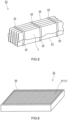
- FIG. 6 shows an example of the air filter unit of the present embodiment.
- An air filter unit 31 shown in FIG. 6 includes the filter pleat pack 21 and a frame 32 supporting the filter pleat pack 21.
- a peripheral portion of the filter pleat pack 21 is supported by the frame (support frame) 32.
- the frame 32 is formed of, for example, a metal, a resin, or a composite material thereof.
- the filter pleat pack 21 can be fixed to the frame 32 at the time of formation of the frame 32.
- the configuration of the frame 32 may be the same as the configuration of a frame included in a conventional air filter unit. Since including the air filter medium 1, the air filter unit 31 is suitable for reducing a pressure drop increase even in an environment including liquid particles such as oil mist.
- the air filter unit 31 of FIG. 6 includes the air filter medium 1 as the filter pleat pack 21.
- the configuration of the air filter unit of the present invention is not limited to the above example as long as the air filter unit includes the air filter medium 1.
- Collection efficiencies CE of the porous PTFE membranes, collection layers, air-permeable supporting layers, and the air filter mediums were evaluated by the above method.
- the evaluation object was one of the air filter mediums
- the air flow was generated in such a direction that the air flow passed through the filter medium from the upstream side to the downstream side shown in Tables 1 and 2.
- the PAO particles used in the evaluation were obtained by generating polydisperse PAO particles using PAO (Durasyn 164) manufactured by INEOS and a constant-output aerosol atomizer (TSI No. 3076 manufactured by TOKYO DYLEC CORP.), classifying the polydisperse PAO particles using a mobility analyzer (TSI No. 3080 manufactured by TOKYO DYLEC CORP.), and selectively collecting particles having a peak in number at a particle size of 0.3 ⁇ m
- the PTFE sheet was held in an atmosphere at 150°C to remove the liquid lubricant.
- the PTFE sheet was stretched by roll stretching in the longitudinal direction at a stretching temperature of 300°C and a stretching ratio of 25 and was then stretched by tenter stretching in the width direction at a stretching temperature of 100°C and a stretching ratio of 30 to obtain an unsintered porous PTFE membrane.
- the obtained porous membrane was sintered at 400°C in a hot-air furnace to obtain a strip-shaped porous PTFE membrane A.
- the obtained porous PTFE membrane A has a thickness of 5 ⁇ m, an initial pressure drop PD 0 of 70 Pa, a collection efficiency of 99.1%, and a PF value of 22.4.
- a glass fiber filter medium (Microfine H750 manufactured by Hokuetsu Paper Mills, Ltd.) was prepared as a collection layer B.
- the collection layer B has a thickness of 380 ⁇ m, a grammage of 63 g/m 2 , an initial pressure drop PD 0 of 50 Pa, and a collection efficiency of 70%, and the glass fiber forming the collection layer B has an average fiber diameter of 0.88 ⁇ m.
- the porous PTFE membrane A and a pair of the air-permeable supporting layers C were stacked in such a manner that the air-permeable supporting layers C sandwiched the porous PTFE membrane A.
- the resulting body as a whole was subjected to thermal lamination at 160°C to obtain a laminate having a three-layer structure composed of "air-permeable supporting layer C/porous PTFE membrane A/air-permeable supporting layer C".
- the obtained laminate and the collection layer B were joined to each other by an air-permeable adhesive layer (grammage: 4 g/m 2 ) to obtain an air filter medium of Example 1.
- the joining was performed by press lamination of the collection layer B to a surface obtained by spraying a hot-melt synthetic rubber adhesive (MORESCO-MELT TN-286Z manufactured by MORESCO Corporation) on one of the exposed surfaces formed of the air-permeable supporting layers C of the laminate so that the grammage would be 4 g/m 2 .
- a hot-melt synthetic rubber adhesive MORESCO-MELT TN-286Z manufactured by MORESCO Corporation
- the air-permeable adhesive layer was observed with an optical microscope to confirm that the air-permeable adhesive layer was formed of the above fibrous adhesive (average fiber diameter: 21 ⁇ m).
- a pair of rolls were used in the thermal lamination and the press lamination (the same applies to Examples and Comparative Examples below).
- the obtained air filter medium was evaluated for the properties in a state where the collection layer B was on the upstream side.
- Example 2 An air filter medium of Example 2 was obtained in the same manner as in Example 1, except that the grammage of the air-permeable adhesive layer was changed to 8 g/m 2 . The obtained air filter medium was evaluated for the properties in a state where the collection layer B was on the upstream side.
- Example 3 An air filter medium of Example 3 was obtained in the same manner as in Example 1, except that the grammage of the air-permeable adhesive layer was changed to 16 g/m 2 . The obtained air filter medium was evaluated for the properties in a state where the collection layer B was on the upstream side.
- Example 4 An air filter medium of Example 4 was obtained in the same manner as in Example 1, except that the grammage of the air-permeable adhesive layer was changed to 24 g/m 2 . The obtained air filter medium was evaluated for the properties in a state where the collection layer B was on the upstream side.
- porous PTFE membrane A and the air-permeable supporting layer C were stacked, and the resulting body as a whole was subjected to thermal lamination at 160°C to obtain a laminate having a double-layer structure composed of "porous PTFE membrane A/air-permeable supporting layer C".
- the obtained laminate and the collection layer B were joined to each other by an air-permeable adhesive layer (grammage: 8 g/m 2 ) to obtain an air filter medium of Example 5.
- the joining was performed by press lamination of the collection layer B to a surface obtained by spraying a hot-melt synthetic rubber adhesive (MORESCO-MELT TN-286Z manufactured by MORESCO Corporation) on the exposed surface formed of the porous PTFE membrane A of the laminate so that the grammage would be 8 g/m 2 .
- the obtained air filter medium was evaluated for the properties in a state where the collection layer B was on the upstream side.
- a laminate having a three-layer structure composed of "air-permeable supporting layer C/porous PTFE membrane A/air-permeable supporting layer C" was obtained in the same manner as in Example 1.
- the obtained laminate and the collection layer B were stacked to obtain an air filter medium of Comparative Example 1.
- the stacking was performed such that one of the air-permeable supporting layers C and the collection layer B were in contact with each other.
- the obtained air filter medium was evaluated for the properties in a state where the collection layer B was on the upstream side.
- a laminate having a double-layer structure composed of "porous PTFE membrane A/air-permeable supporting layer C" was obtained in the same manner as in Example 5.
- the obtained laminate and the collection layer B were stacked to obtain an air filter medium of Comparative Example 2.
- the stacking was performed such that the porous PTFE membrane A and the collection layer B were in contact with each other.
- the obtained air filter medium was evaluated for the properties in a state where the collection layer B was on the upstream side.
- Tables 1 and 2 below show configurations and properties of the air filter mediums of Examples and Comparative Examples.
- Example 1 Example 2
- Example 3 Example 4
- Example 5 ⁇ Upstream side Collection layer No. B B B B B Air-permeable adhesive layer Grammage (g/m 2 ) 4 8 16 24 8 Air-permeable supporting layer No. C C C Downstreamside ⁇ Porous PTFE membrane No. A A A A A A Air-permeable supporting layer No.
- Table 3 shows the results of the evaluation for the holding amounts Y of the air filter mediums of Examples 1 to 4 having the same configurations except for the grammages of the air-permeable adhesive layers. [Table 3] Example 1 Example 2 Example 3 Example 4 Holding amount Y (g/m 2 ) 78.3 78.6 80.2 78.5
- the air filter medium of the present invention can be used in the same applications as conventional air filter mediums.
- Examples of the applications include air filter mediums, filter pleat packs, and air filter units used as air-intake filters for outside air treatment and air-intake filters of turbines.
Applications Claiming Priority (2)
| Application Number | Priority Date | Filing Date | Title |
|---|---|---|---|
| JP2020162643 | 2020-09-28 | ||
| PCT/JP2021/035724 WO2022065517A1 (ja) | 2020-09-28 | 2021-09-28 | エアフィルタ濾材、フィルタプリーツパック及びエアフィルタユニット |
Publications (1)
| Publication Number | Publication Date |
|---|---|
| EP4218983A1 true EP4218983A1 (de) | 2023-08-02 |
Family
ID=80845498
Family Applications (1)
| Application Number | Title | Priority Date | Filing Date |
|---|---|---|---|
| EP21872642.0A Pending EP4218983A1 (de) | 2020-09-28 | 2021-09-28 | Luftfilterfiltermedium, filterfaltpack und luftfiltereinheit |
Country Status (6)
| Country | Link |
|---|---|
| US (1) | US20230372858A1 (de) |
| EP (1) | EP4218983A1 (de) |
| JP (1) | JPWO2022065517A1 (de) |
| KR (1) | KR20230079108A (de) |
| CN (1) | CN116261484A (de) |
| WO (1) | WO2022065517A1 (de) |
Family Cites Families (7)
| Publication number | Priority date | Publication date | Assignee | Title |
|---|---|---|---|---|
| JPH08103612A (ja) * | 1994-10-04 | 1996-04-23 | Nitto Denko Corp | 粘着型集塵フィルタ |
| JP3506192B2 (ja) * | 1995-05-15 | 2004-03-15 | 東洋紡績株式会社 | 積層濾材及びその製造方法 |
| CN103764251B (zh) | 2011-08-31 | 2015-07-22 | 大金工业株式会社 | 空气过滤器用滤材、空气过滤器单元以及空气过滤器用滤材的制造方法 |
| JP5784458B2 (ja) * | 2011-10-31 | 2015-09-24 | 日東電工株式会社 | エアフィルタ濾材 |
| JP6372507B2 (ja) * | 2016-03-11 | 2018-08-15 | ダイキン工業株式会社 | エアフィルタ用濾材、エアフィルタユニット、およびエアフィルタ用濾材の製造方法 |
| WO2019059382A1 (ja) * | 2017-09-22 | 2019-03-28 | 日東電工株式会社 | エアフィルタ濾材、フィルタプリーツパックおよびエアフィルタユニット |
| EP3858456A4 (de) * | 2018-09-28 | 2022-07-20 | Daikin Industries, Ltd. | Filtermedium für luftfilter, filterpack, luftfiltereinheit und herstellungsverfahren dafür |
-
2021
- 2021-09-28 EP EP21872642.0A patent/EP4218983A1/de active Pending
- 2021-09-28 KR KR1020237013453A patent/KR20230079108A/ko unknown
- 2021-09-28 US US18/027,699 patent/US20230372858A1/en active Pending
- 2021-09-28 WO PCT/JP2021/035724 patent/WO2022065517A1/ja active Application Filing
- 2021-09-28 CN CN202180066227.4A patent/CN116261484A/zh active Pending
- 2021-09-28 JP JP2022552119A patent/JPWO2022065517A1/ja active Pending
Also Published As
| Publication number | Publication date |
|---|---|
| WO2022065517A1 (ja) | 2022-03-31 |
| JPWO2022065517A1 (de) | 2022-03-31 |
| CN116261484A (zh) | 2023-06-13 |
| KR20230079108A (ko) | 2023-06-05 |
| US20230372858A1 (en) | 2023-11-23 |
Similar Documents
| Publication | Publication Date | Title |
|---|---|---|
| EP2733163B1 (de) | Poröser polytetrafluorethylenfilm und filtermaterial für luftfilter | |
| EP3357564B1 (de) | Luftfiltermedium, luftfilterpack und luftfiltereinheit | |
| EP3520874B1 (de) | Luftfiltermaterial, luftfilterpack und luftfiltereinheit | |
| KR102255737B1 (ko) | 에어 필터 여과재의 제조 방법, 에어 필터 여과재 및 에어 필터 팩 | |
| EP3520873B1 (de) | Luftfiltermaterial, luftfilterpack und luftfiltereinheit | |
| CN111148561B (zh) | 空气过滤器滤材、过滤器褶裥组件及空气过滤器单元 | |
| EP3520875B1 (de) | Luftfiltermaterial, luftfilterpack und luftfiltereinheit | |
| EP3275531B1 (de) | Filtermaterial und filtereinheit | |
| EP3292906B1 (de) | Filtermaterial und filtereinheit | |
| EP4218983A1 (de) | Luftfilterfiltermedium, filterfaltpack und luftfiltereinheit | |
| EP3804832A1 (de) | Filtermedium und filtereinheit damit | |
| EP4218982A1 (de) | Luftfilterfilterelement, filterfaltpack und luftfiltereinheit | |
| US20230364547A1 (en) | Air filter medium, filter pleat pack, and air filter unit | |
| EP4238635A1 (de) | Filterfaltpack und luftfiltereinheit | |
| EP3903902A1 (de) | Filterfaltenpaket und luftfiltereinheit | |
| EP3903903A1 (de) | Filterfaltenpaket und luftfiltereinheit |
Legal Events
| Date | Code | Title | Description |
|---|---|---|---|
| STAA | Information on the status of an ep patent application or granted ep patent |
Free format text: STATUS: THE INTERNATIONAL PUBLICATION HAS BEEN MADE |
|
| PUAI | Public reference made under article 153(3) epc to a published international application that has entered the european phase |
Free format text: ORIGINAL CODE: 0009012 |
|
| STAA | Information on the status of an ep patent application or granted ep patent |
Free format text: STATUS: REQUEST FOR EXAMINATION WAS MADE |
|
| 17P | Request for examination filed |
Effective date: 20230330 |
|
| AK | Designated contracting states |
Kind code of ref document: A1 Designated state(s): AL AT BE BG CH CY CZ DE DK EE ES FI FR GB GR HR HU IE IS IT LI LT LU LV MC MK MT NL NO PL PT RO RS SE SI SK SM TR |
|
| DAV | Request for validation of the european patent (deleted) | ||
| DAX | Request for extension of the european patent (deleted) |