EP4218693B1 - Opthalmic medical instrument with illuminated snare - Google Patents
Opthalmic medical instrument with illuminated snare Download PDFInfo
- Publication number
- EP4218693B1 EP4218693B1 EP23154125.1A EP23154125A EP4218693B1 EP 4218693 B1 EP4218693 B1 EP 4218693B1 EP 23154125 A EP23154125 A EP 23154125A EP 4218693 B1 EP4218693 B1 EP 4218693B1
- Authority
- EP
- European Patent Office
- Prior art keywords
- light
- conducting element
- surgical instrument
- looped segment
- ophthalmic surgical
- Prior art date
- Legal status (The legal status is an assumption and is not a legal conclusion. Google has not performed a legal analysis and makes no representation as to the accuracy of the status listed.)
- Active
Links
Images




Classifications
-
- A—HUMAN NECESSITIES
- A61—MEDICAL OR VETERINARY SCIENCE; HYGIENE
- A61F—FILTERS IMPLANTABLE INTO BLOOD VESSELS; PROSTHESES; DEVICES PROVIDING PATENCY TO, OR PREVENTING COLLAPSING OF, TUBULAR STRUCTURES OF THE BODY, e.g. STENTS; ORTHOPAEDIC, NURSING OR CONTRACEPTIVE DEVICES; FOMENTATION; TREATMENT OR PROTECTION OF EYES OR EARS; BANDAGES, DRESSINGS OR ABSORBENT PADS; FIRST-AID KITS
- A61F9/00—Methods or devices for treatment of the eyes; Devices for putting in contact-lenses; Devices to correct squinting; Apparatus to guide the blind; Protective devices for the eyes, carried on the body or in the hand
- A61F9/007—Methods or devices for eye surgery
- A61F9/00736—Instruments for removal of intra-ocular material or intra-ocular injection, e.g. cataract instruments
-
- A—HUMAN NECESSITIES
- A61—MEDICAL OR VETERINARY SCIENCE; HYGIENE
- A61B—DIAGNOSIS; SURGERY; IDENTIFICATION
- A61B90/00—Instruments, implements or accessories specially adapted for surgery or diagnosis and not covered by any of the groups A61B1/00 - A61B50/00, e.g. for luxation treatment or for protecting wound edges
- A61B90/30—Devices for illuminating a surgical field, the devices having an interrelation with other surgical devices or with a surgical procedure
- A61B2090/306—Devices for illuminating a surgical field, the devices having an interrelation with other surgical devices or with a surgical procedure using optical fibres
-
- A—HUMAN NECESSITIES
- A61—MEDICAL OR VETERINARY SCIENCE; HYGIENE
- A61B—DIAGNOSIS; SURGERY; IDENTIFICATION
- A61B90/00—Instruments, implements or accessories specially adapted for surgery or diagnosis and not covered by any of the groups A61B1/00 - A61B50/00, e.g. for luxation treatment or for protecting wound edges
- A61B90/30—Devices for illuminating a surgical field, the devices having an interrelation with other surgical devices or with a surgical procedure
- A61B2090/309—Devices for illuminating a surgical field, the devices having an interrelation with other surgical devices or with a surgical procedure using white LEDs
Definitions
- This invention relates to an ophthalmic medical instrument containing a snare for bisecting a patient's lens to facilitate removal during cataract surgery.
- the invention relates to a medical instrument having a snare that is illuminated via a light conducting tube that surrounds the snare.
- Snare devices have been used to bisect a patient's lens during cataract surgery, in order to facilitate removal of the lens.
- the device has generally taken the form of an elongated shaft with a wire extending out or near a distal end of the shaft.
- the wire is in form of a loop that is placed around the lens and then contracted, so that the wire severs the lens and allows the severed lens to be removed from the surrounding lens capsule more easily.
- One of the problems with the traditional snare devices is that the surgeon cannot see the wire behind the lens, so accurate placement is difficult, and can complicate the surgery.
- One attempt to make the wire snare more visible is described in United States Patent No. 10,485,700 to Mackool .
- the wire is constructed to be hollow and a light source is in communication with the lumen of the wire.
- a light source is in communication with the lumen of the wire.
- An aperture in the wire at a point located behind the lens allows the light to escape. The light can be seen through the lens to identify the location of the wire to the surgeon.
- an ophthalmic surgical instrument for severing a lens of an eye comprising an elongated shaft having a distal end portion, and a snare formed by a wire extending along the elongated shaft and having a looped segment disposed adjacent the distal end portion and being configured to move between a contracted configuration and a dilated configuration, in which the looped segment assumes a diameter approximating the diameter and shape of a lens of an eye.
- a light-conducting element extends along at least a portion of a length of the looped segment and a light source is in communication with the light-conducting element, such that light from the light source travels through the light-conducting element and illuminates at least a portion of the length of the looped segment, in order to enable the surgeon to visualize the looped segment after it is placed around the lens.
- the light-conducting element is adjacent at least a portion of a length of the looped segment, either by providing the light-conducting element in form of a tube that surrounds the wire or by providing the light-conducting element in form of a solid filament that extends adjacent to the wire.
- the light from the light source travels through the material of the element and exits out a distal end of the element, which can be located at any point along the looped segment but preferably at a place located behind the lens during surgery and preferably at a center of the lens.
- the point at which the light exits the end of the element forms a bright spot that can be seen through the lens during cataract surgery, so that proper positioning of the snare formed by the looped segment is ensured.
- the light-conducting element is in the form of a solid filament that runs adjacent the wire.
- the light-conducting element is preferably made of polyurethane, but any other suitable transparent, translucent or opaque flexible material that scatters light could be used.
- the light conducting element and wire can be covered by an opaque covering so that light from the light source is only visible at an end of the element.
- the end of the light-conducting element should be positioned behind the lens during surgery, as this the only area where the light is visible. It is also possible to provide openings along the length of the covering for additional bright spots if desired.
- the opaque covering can be made of metal, plastic or any other suitable material.
- the covering could be woven, braided, coiled, painted or laminated or in any suitable configuration that would allow for movement of the tube and wire during contraction and dilation.
- the wire is preferably made of nitinol, which has shape memory capabilities so that an oval shape of the looped segment is maintained throughout use. Other suitable materials could also be used.
- the looped portion of the wire has a bend at a bottom of the loop. If the light-conducting element terminates at the bend, the end of the light-conducting element faces toward the shaft, and thus light exiting from the light-conducing element is directed through the lens and back toward the surgeon for maximum visibility.
- the instrument includes a housing connected to the elongated shaft.
- the housing has an actuator connected to the wire and is configured to move the wire between the contracted and dilated configurations.
- the light source is disposed in the housing and the light-conducting element extends through the elongated shaft into the housing where it is connected to the light source.
- the light source is located external to the housing and the light-conducting element extends through the housing and out of the housing to the external light source.
- the actuator can take on any suitable form.
- the actuator is formed by a sliding element disposed in a slot in the housing. Sliding the sliding element in a direction away from the distal end of the elongated shaft moves the wire into the contracted position, causing the wire to sever the lens, and sliding the sliding element toward the distal end of the elongated shaft moves the wire into the dilated position where it is ready for use.
- the light source could be formed by any suitable light source, such as a light-emitting diode (LED). If the light source is disposed in the housing, it is preferably powered by a battery disposed in the housing, so that the instrument is portable and does not require a wired connection to a power source. Alternatively, the light source could be located remote from the surgical instrument, and the tube could extend through the instrument to the light source.
- a light-emitting diode LED
- FIGS. 1-3 show an ophthalmic surgical instrument 1 that has a housing 10, an elongated shaft in the form of a needle 20 having a distal end 21, an opening 22 in a side wall thereof, and a snare 30 formed by a wire, for severing lenticular tissue.
- the elongated shaft 20 is dimensioned for passage through a corneal incision and has a proximal end portion 23 that may be integrally formed with or attached to the housing 10 or to a slider cartridge 40 shown in FIG. 2 .
- the snare 30 of the ophthalmic surgical instrument 1 is movable relative to and within the elongated shaft 20 via an actuation mechanism formed by slider cartridge 40 and slider button 45, which rests in channel 41 of slider cartridge 40.
- Slider cartridge 40 is accessible through an opening 15 in housing 10.
- a first end of snare 30 is connected to slider button 45, as shown in FIG. 4 , and the second end of snare 30 is fixed within the housing, so that moving slider button 45 along channel 41 expands and retracts looped segment 33 formed by snare 30. Retracting looped segment 33 by sliding button 45 away from distal end 22 allows snare 30 to bisect a lens that is disposed within loop 33 during surgery.
- the snare 30 is fabricated from a pliable, metal material, such as, for example, nickel-titanium or any other suitable superelastic material.
- the snare may be fabricated from any suitable ductile material.
- a light-conducting tube 50 Surrounding the snare 30 is a light-conducting tube 50, which extends at least partially around the looped segment 33. In the embodiment of FIGS. 1-4 , tube 50 terminates at a distal end 51, which is located at a bottom of the looped segment 33. As shown in FIG. 4 , tube 50 extends around the top portion of looped segment 33, enters the elongated shaft 20 with snare 30, extends through slider cartridge 40, and connects to a light source 60, which is disposed in housing 10.
- Light source 60 can be connected to power source 70, such as a battery, also disposed in housing 10, so that the ophthalmic surgical instrument 1 is completely portable and wireless.
- the light source 60 may be a light-emitting diode (LED), a compact fluorescent lamp, an incandescent light bulb, or any other suitable source of light.
- the light source 60 is in communication with the tube 50 so that the light from the light source is emitted out of the tube and out of distal end 51.
- Tube 50 is also preferably made of a flexible, translucent material such as polyurethane, so that the light is emitted along the length of the tube 50 and is visible along the entire length. In this embodiment, the light would appear as a bright spot at the distal end 51 exit as well.
- Tube 50 is made of an opaque material, or is covered by an opaque coating or covering, so that only the light exiting out of distal end 51 is visible.
- tube 50 can be covered by a metal covering.
- the elongated shaft 20 is inserted through a corneal incision and a capsulorhexis to position the distal end portion 21 around a surface of the lens L.
- the surgeon is able to use the light emitted from the tube 50 to appropriately position the snare 30 relative to the lens "L.”
- the looped segment 33 With the looped segment 33 in the selected position, which is verified using the light transmitted out of the bottom 51 of tube 50, the looped segment 33 is transitioned from the dilated configuration to the contracted configuration, thereby severing the lens "L.”
- FIG. 5 shows an alternative embodiment of the invention, where device 100 has an elongated shaft 200 with an opening 220 through which a snare 300 formed by wire extends in a looped segment 330.
- Snare 300 is completely encased in a light-conducting tube 500, which is connected to a light source 600, in the same manner as described above with respect to FIGS. 1-4 .
- Tube 500 is transparent or translucent, so that the light from light source 600 is visible along the entire extent of the snare.
- Tube 500 is thin enough so that snare 300 surrounded by tube 500 is still able to bisect a lens when snare 300 is moved to the retracted position in the manner described above with respect to FIGS. 1-4 (using the same slider mechanism as described above).
- FIG. 6 shows another alternative embodiment, where light source 660 is located outside the housing 10 of ophthalmic surgical instrument 1. Snare 350 surrounded by tube 550 extends entirely through the housing and out to remote light source 660, which can be located on a remote device or by itself. This embodiment allows for the use of a larger, more powerful light source and a larger power supply than may be available to place inside housing 10.
- FIGS. 7 and 8 An alternative embodiment of the invention is shown in FIGS. 7 and 8 .
- a light-conducting element in the form of a solid filament 5500 extends parallel to snare 3000, and terminates at a mid-point of looped segment 3300 of snare 3000.
- a coiled cover 4000 surrounds the snare 3000 and filament 5500 to keep the two components together.
- Cover 4000 can be formed of metal wire or any other suitable material, such as a polymer, or any other suitable mixture of materials.
- the light from filament 5500 exits out of end 5510 and forms a bright spot behind the lens during surgery, in the same manner as explained above with respect to FIGS 1-4 .
- Filament 5500 is connected to a light source that is disposed in the housing 10 or in a location remote from housing 10 in the same manner as disclosed with the embodiments of FIGS. 1-6 .
- FIG. 9 shows a further embodiment of the invention, which is identical to the embodiment of FIGS. 7 and 8 , using the instrument of FIGS. 1-6 , except that in this situation, cover 8000 is in the form of a woven material, typically a metallic tape or thread, but any other suitable materials could be used as well. It is also envisioned that a cover could be constructed of a solid tube or a molded material that covers both the snare 3000 and the filament 5500.
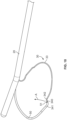
- FIG. 10 A further embodiment is shown in FIG. 10 , here the ophthalmic surgical instrument 1 is identical to the instrument shown in FIGS. 1-4 , except that here, snare 30 is bent in two places in opposite directions at a bottom of looped portion 33, in the form of a Z- or S-shape, so that an intermediate section 340 between bends 341 and 342 extends upward toward elongated shaft 20, obliquely to the extent of looped portion 33.
- Tube 50 terminates in the intermediate section 340, so that distal end 51 is aimed toward elongated shaft 20.
Landscapes
- Health & Medical Sciences (AREA)
- Ophthalmology & Optometry (AREA)
- Heart & Thoracic Surgery (AREA)
- Surgery (AREA)
- Engineering & Computer Science (AREA)
- Biomedical Technology (AREA)
- Nuclear Medicine, Radiotherapy & Molecular Imaging (AREA)
- Vascular Medicine (AREA)
- Life Sciences & Earth Sciences (AREA)
- Animal Behavior & Ethology (AREA)
- General Health & Medical Sciences (AREA)
- Public Health (AREA)
- Veterinary Medicine (AREA)
- Surgical Instruments (AREA)
Description
- This invention relates to an ophthalmic medical instrument containing a snare for bisecting a patient's lens to facilitate removal during cataract surgery. In particular, the invention relates to a medical instrument having a snare that is illuminated via a light conducting tube that surrounds the snare.
- Snare devices have been used to bisect a patient's lens during cataract surgery, in order to facilitate removal of the lens. The device has generally taken the form of an elongated shaft with a wire extending out or near a distal end of the shaft. The wire is in form of a loop that is placed around the lens and then contracted, so that the wire severs the lens and allows the severed lens to be removed from the surrounding lens capsule more easily. One of the problems with the traditional snare devices is that the surgeon cannot see the wire behind the lens, so accurate placement is difficult, and can complicate the surgery. One attempt to make the wire snare more visible is described in
United States Patent No. 10,485,700 to Mackool
communication with the lumen of the wire. An aperture in the wire at a point located behind the lens allows the light to escape. The light can be seen through the lens to identify the location of the wire to the surgeon. - One drawback to this configuration is that manufacturing and assembling the wire with the light source is expensive and cumbersome. In addition, the wire must be made larger to accommodate the lumen, and is thus less effective in severing the lens during use. As these devices are generally not re-used, it would be desirable to provide a device for severing a lens that is simple and inexpensive to manufacture as well as effective and reliable during use.
- It is therefore an object of the invention to provide an ophthalmic device for severing a lens, in which the wire forming the snare is not required to be hollow. This object is accomplished by an ophthalmic surgical instrument for severing a lens of an eye, comprising an elongated shaft having a distal end portion, and a snare formed by a wire extending along the elongated shaft and having a looped segment disposed adjacent the distal end portion and being configured to move between a contracted configuration and a dilated configuration, in which the looped segment assumes a diameter approximating the diameter and shape of a lens of an eye. When the elongated shaft is inserted through the pupil and the looped segment is placed around the lens, the bottom portion of the looped segment is configured to engage and sever a bottom portion of the lens upon moving toward the contracted configuration. This enables the surgeon to more easily remove the lens during surgery. A light-conducting element extends along at least a portion of a length of the looped segment and a light source is in communication with the light-conducting element, such that light from the light source travels through the light-conducting element and illuminates at least a portion of the length of the looped segment, in order to enable the surgeon to visualize the looped segment after it is placed around the lens.
- According to the invention the light-conducting element is adjacent at least a portion of a length of the looped segment, either by providing the light-conducting element in form of a tube that surrounds the wire or by providing the light-conducting element in form of a solid filament that extends adjacent to the wire. The light from the light source travels through the material of the element and exits out a distal end of the element, which can be located at any point along the looped segment but preferably at a place located behind the lens during surgery and preferably at a center of the lens. The point at which the light exits the end of the element forms a bright spot that can be seen through the lens during cataract surgery, so that proper positioning of the snare formed by the looped segment is ensured.
- In one embodiment, the light-conducting element is in the form of a solid filament that runs adjacent the wire.
- In another embodiment, the light-conducting element is in the form of a tube that surrounds the wire. The tubular structure surrounding the wire creates a greater surface area for light emission as compared to a single strand, thus increasing the visibility of the snare during use.
- In a further embodiment, the entire light-conducting element is translucent or transparent, so that the light exits along the length of the element as well, illuminating the entire extent of the looped segment. In this situation, the light-conducting element may extend along an entire length of the looped segment, so that the entire snare is illuminated during surgery. In this embodiment wherein the element tube, the tube is constructed to have a small enough diameter so it can still function to sever the lens during contraction of the wire.
- The light-conducting element is preferably made of polyurethane, but any other suitable transparent, translucent or opaque flexible material that scatters light could be used.
- In another embodiment, the light conducting element and wire can be covered by an opaque covering so that light from the light source is only visible at an end of the element. In this embodiment, the end of the light-conducting element should be positioned behind the lens during surgery, as this the only area where the light is visible. It is also possible to provide openings along the length of the covering for additional bright spots if desired.
- The opaque covering can be made of metal, plastic or any other suitable material. The covering could be woven, braided, coiled, painted or laminated or in any suitable configuration that would allow for movement of the tube and wire during contraction and dilation.
- The wire is preferably made of nitinol, which has shape memory capabilities so that an oval shape of the looped segment is maintained throughout use. Other suitable materials could also be used. In one embodiment, the looped portion of the wire has a bend at a bottom of the loop. If the light-conducting element terminates at the bend, the end of the light-conducting element faces toward the shaft, and thus light exiting from the light-conducing element is directed through the lens and back toward the surgeon for maximum visibility.
- In a preferred embodiment, the instrument includes a housing connected to the elongated shaft. The housing has an actuator connected to the wire and is configured to move the wire between the contracted and dilated configurations. Preferably, the light source is disposed in the housing and the light-conducting element extends through the elongated shaft into the housing where it is connected to the light source. In another embodiment, the light source is located external to the housing and the light-conducting element extends through the housing and out of the housing to the external light source.
- The actuator can take on any suitable form. In one embodiment, the actuator is formed by a sliding element disposed in a slot in the housing. Sliding the sliding element in a direction away from the distal end of the elongated shaft moves the wire into the contracted position, causing the wire to sever the lens, and sliding the sliding element toward the distal end of the elongated shaft moves the wire into the dilated position where it is ready for use.
- The light source could be formed by any suitable light source, such as a light-emitting diode (LED). If the light source is disposed in the housing, it is preferably powered by a battery disposed in the housing, so that the instrument is portable and does not require a wired connection to a power source. Alternatively, the light source could be located remote from the surgical instrument, and the tube could extend through the instrument to the light source.
- Other objects and features of the present invention will become apparent from the following detailed description considered in connection with the accompanying drawings. It is to be understood, however, that the drawings are designed as an illustration only and not as a definition of the limits of the invention.
- In the drawings, wherein similar reference characters denote similar elements throughout the several views:
-
FIG. 1 shows a side view of the ophthalmic surgical instrument according to the invention; -
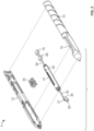
FIG. 2 shows the instrument with the housing cover removed; -
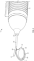
FIG. 3 shows an enlarged view of the instrument; -
FIG. 4 shows a cross-sectional view of the instrument along lines 4-4 ofFIG. 1 ; -
FIG. 5 shows an alternative embodiment of the snare; -
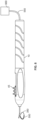
FIG. 6 shows an alternative embodiment of the instrument, with an external light source; -
FIG. 7 shows another alternative embodiment of the invention; -
FIG. 8 shows an enlarged view ofcircle 8 inFIG. 7 ; -
FIG. 9 shows another alternative embodiment of the invention; and -
FIG. 10 shows a further embodiment of the invention. - Turning to the drawings,
FIGS. 1-3 show an ophthalmicsurgical instrument 1 that has ahousing 10, an elongated shaft in the form of aneedle 20 having adistal end 21, anopening 22 in a side wall thereof, and asnare 30 formed by a wire, for severing lenticular tissue. Theelongated shaft 20 is dimensioned for passage through a corneal incision and has aproximal end portion 23 that may be integrally formed with or attached to thehousing 10 or to aslider cartridge 40 shown inFIG. 2 . - The
snare 30 of the ophthalmicsurgical instrument 1 is movable relative to and within theelongated shaft 20 via an actuation mechanism formed byslider cartridge 40 andslider button 45, which rests inchannel 41 ofslider cartridge 40.Slider cartridge 40 is accessible through anopening 15 inhousing 10. A first end ofsnare 30 is connected toslider button 45, as shown inFIG. 4 , and the second end ofsnare 30 is fixed within the housing, so that movingslider button 45 alongchannel 41 expands and retracts loopedsegment 33 formed bysnare 30. Retracting loopedsegment 33 by slidingbutton 45 away fromdistal end 22 allowssnare 30 to bisect a lens that is disposed withinloop 33 during surgery. - The
snare 30 is fabricated from a pliable, metal material, such as, for example, nickel-titanium or any other suitable superelastic material. The snare may be fabricated from any suitable ductile material. Surrounding thesnare 30 is a light-conductingtube 50, which extends at least partially around the loopedsegment 33. In the embodiment ofFIGS. 1-4 ,tube 50 terminates at adistal end 51, which is located at a bottom of the loopedsegment 33. As shown inFIG. 4 ,tube 50 extends around the top portion of loopedsegment 33, enters theelongated shaft 20 withsnare 30, extends throughslider cartridge 40, and connects to alight source 60, which is disposed inhousing 10.Light source 60 can be connected topower source 70, such as a battery, also disposed inhousing 10, so that the ophthalmicsurgical instrument 1 is completely portable and wireless. - The
light source 60 may be a light-emitting diode (LED), a compact fluorescent lamp, an incandescent light bulb, or any other suitable source of light. Thelight source 60 is in communication with thetube 50 so that the light from the light source is emitted out of the tube and out ofdistal end 51.Tube 50 is also preferably made of a flexible, translucent material such as polyurethane, so that the light is emitted along the length of thetube 50 and is visible along the entire length. In this embodiment, the light would appear as a bright spot at thedistal end 51 exit as well. In another embodiment,Tube 50 is made of an opaque material, or is covered by an opaque coating or covering, so that only the light exiting out ofdistal end 51 is visible. In one embodiment,tube 50 can be covered by a metal covering. - In use, the
elongated shaft 20 is inserted through a corneal incision and a capsulorhexis to position thedistal end portion 21 around a surface of the lens L. The surgeon is able to use the light emitted from thetube 50 to appropriately position thesnare 30 relative to the lens "L." With the loopedsegment 33 in the selected position, which is verified using the light transmitted out of the bottom 51 oftube 50, the loopedsegment 33 is transitioned from the dilated configuration to the contracted configuration, thereby severing the lens "L." -
FIG. 5 shows an alternative embodiment of the invention, where device 100 has an elongatedshaft 200 with an opening 220 through which asnare 300 formed by wire extends in a loopedsegment 330. Snare 300 is completely encased in a light-conductingtube 500, which is connected to alight source 600, in the same manner as described above with respect toFIGS. 1-4 .Tube 500 is transparent or translucent, so that the light fromlight source 600 is visible along the entire extent of the snare.Tube 500 is thin enough so thatsnare 300 surrounded bytube 500 is still able to bisect a lens whensnare 300 is moved to the retracted position in the manner described above with respect toFIGS. 1-4 (using the same slider mechanism as described above). -
FIG. 6 shows another alternative embodiment, wherelight source 660 is located outside thehousing 10 of ophthalmicsurgical instrument 1. Snare 350 surrounded bytube 550 extends entirely through the housing and out to remotelight source 660, which can be located on a remote device or by itself. This embodiment allows for the use of a larger, more powerful light source and a larger power supply than may be available to place insidehousing 10. - An alternative embodiment of the invention is shown in
FIGS. 7 and8 . Here, a light-conducting element in the form of asolid filament 5500 extends parallel to snare 3000, and terminates at a mid-point of loopedsegment 3300 ofsnare 3000. Acoiled cover 4000 surrounds thesnare 3000 andfilament 5500 to keep the two components together.Cover 4000 can be formed of metal wire or any other suitable material, such as a polymer, or any other suitable mixture of materials. In this embodiment, the light fromfilament 5500 exits out ofend 5510 and forms a bright spot behind the lens during surgery, in the same manner as explained above with respect toFIGS 1-4 .Filament 5500 is connected to a light source that is disposed in thehousing 10 or in a location remote fromhousing 10 in the same manner as disclosed with the embodiments ofFIGS. 1-6 . -
FIG. 9 shows a further embodiment of the invention, which is identical to the embodiment ofFIGS. 7 and8 , using the instrument ofFIGS. 1-6 , except that in this situation,cover 8000 is in the form of a woven material, typically a metallic tape or thread, but any other suitable materials could be used as well. It is also envisioned that a cover could be constructed of a solid tube or a molded material that covers both thesnare 3000 and thefilament 5500. - A further embodiment is shown in
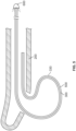
FIG. 10 , here the ophthalmicsurgical instrument 1 is identical to the instrument shown inFIGS. 1-4 , except that here, snare 30 is bent in two places in opposite directions at a bottom of loopedportion 33, in the form of a Z- or S-shape, so that anintermediate section 340 betweenbends elongated shaft 20, obliquely to the extent of loopedportion 33.Tube 50 terminates in theintermediate section 340, so thatdistal end 51 is aimed towardelongated shaft 20. Thus, the bright spot formed by thelight exiting tube 50 is aimed toward the surgeon during surgery (along arrow A), and is thus more visible, even when viewed through a lens that is substantially opaque with a cataract. The snare ofFIG. 10 could also be used in an embodiment where the light-conducting element is in the form of a solid filament such as shown byfilament 5500 inFIGS. 7-9 . In either case, the end of the light-conducting element is aimed back toward theelongated shaft 20, so that the brightest part of the apparatus is aimed at the surgeon, thus making the snare more visible behind the lens. The light-conducting element could be covered or coated so that the light is only visible atend 51, such as shown in the embodiment ofFIGS. 7-9 , or can be uncovered so that light is visible along the extent of the light-conducting element, i.e.,tube 50. - Accordingly, while only a few embodiments of the present invention have been shown and described, it is obvious that many changes and modifications may be made thereunto according to the invention as defined by the claims.
Claims (14)
- An ophthalmic surgical instrument (1) for severing a lens (L) of an eye, comprising:an elongated shaft (20, 200) having a distal end portion (21);a wire (30, 300, 350) extending along the elongated shaft (20, 200) and having a looped segment (33, 330) disposed adjacent the distal end portion (21) and being configured to move between a contracted configuration and a dilated configuration, in which the looped segment (33, 330) assumes a diameter approximating the diameter and shape of a lens (L) of an eye, the looped segment (33, 330) having a bottom portion configured to engage and sever a bottom portion of the lens (L) upon moving toward the contracted configuration when the looped segment (33, 330) is placed around the lens (L),a light-conducting element (50, 500, 550) extending along at least a portion of a length of the looped segment (33, 330), anda light source (60, 600, 660) in communication with the light-conducting element (50, 500, 550), such that light from the light source (60, 600, 660) travels through the light-conducting element (50, 500, 550) and illuminates at least a portion of the length of the looped segment (33, 330),characterized in that the light-conducting element (50, 500, 550) is a tube that surrounds the wire (30, 300, 350).
- An ophthalmic surgical instrument (1) for severing a lens (L) of an eye, comprising:an elongated shaft (20, 200) having a distal end portion (21);a wire (3000) extending along the elongated shaft (20, 200) and having a looped segment (3300) disposed adjacent the distal end portion (21) and being configured to move between a contracted configuration and a dilated configuration, in which the looped segment (3300) assumes a diameter approximating the diameter and shape of a lens (L) of an eye, the looped segment (3300) having a bottom portion configured to engage and sever a bottom portion of the lens (L) upon moving toward the contracted configuration when the looped segment (3300) is placed around the lens (L),a light-conducting element (5500) extending along at least a portion of a length of the looped segment (3300), anda light source (60, 600, 660) in communication with the light-conducting element (5500), such that light from the light source (60, 600, 660) travels through the light-conducting element (5500) and illuminates at least a portion of the length of the looped segment (3300),characterized in that the light-conducting element (5500) is a solid filament that extends adjacent to the wire (3000).
- The ophthalmic surgical instrument according to claim 1 or 2, wherein the light-conducting element (50, 500, 550, 5500) is translucent.
- The ophthalmic surgical instrument according to any of claims 1 to 3, wherein the light-conducting element (50, 500, 550, 5500) terminates at the bottom portion of the looped segment (33, 330, 3300), and light from the light source (60, 600, 660) exits the light-conducting element (50, 500, 550, 5500) at the bottom portion of the looped segment (33, 330, 3300).
- The ophthalmic surgical instrument according to any of claims 1 to 4, wherein the light-conducting element (50, 500, 550, 5500) is made of polyurethane.
- The ophthalmic surgical instrument according to claim 4 or 5, wherein the light-conducting element (50, 500, 550, 5500) is opaque, or covered by an opaque coating or covering (4000, 8000), so that light from the light source (60, 600, 660) is only visible at an end of the light-conducting element (50, 500, 550, 5500).
- The ophthalmic surgical instrument according to any of claims 1 to 6, wherein the wire (30, 300, 350, 3000) is made of nitinol.
- The ophthalmic surgical instrument according to any of claims 1 to 7, wherein the light-conducting element (50, 500, 550, 5500) extends through the elongated shaft (20, 200).
- The ophthalmic surgical instrument according to any of claims 1 to 8, further comprising a housing (10) connected to the elongated shaft (20, 200), the housing (10) comprising an actuator (40) connected to the wire (30, 300, 350, 3000) and being configured to move the wire (30, 300, 350, 3000) between the contracted and dilated configurations.
- The ophthalmic surgical instrument according to any of claims 1 to 9, wherein the light source (60, 600, 660) is a light-emitting diode (LED).
- The ophthalmic surgical instrument according to any of claims 6 to 10, wherein the light-conducting element (50, 500, 550, 5500) and wire (30, 300, 350, 3000) are covered by a covering (4000, 8000) that is woven or coiled.
- The ophthalmic surgical instrument according to claim 11, wherein the covering (4000, 8000) is made of metal.
- The ophthalmic surgical instrument according to any of claims 1 to 12, wherein the wire (30, 300, 350, 3000) is bent in two places in opposite directions at an approximate mid-point of the looped segment (33, 330, 3300), so as to create an intermediate section (340) that is not parallel to the looped segment (33, 330, 3300).
- The ophthalmic surgical instrument according to claim 13, wherein the light-transmitting element (50, 500, 550, 5500) terminates at the intermediate section (340) of the looped segment (33, 330, 3300), so that a distal end of the light-transmitting element (50, 500, 550, 5500) is facing the elongated shaft (20, 200).
Applications Claiming Priority (1)
| Application Number | Priority Date | Filing Date | Title |
|---|---|---|---|
| US17/590,081 US11432960B1 (en) | 2022-02-01 | 2022-02-01 | Ophthalmic medical instrument with illuminated snare |
Publications (3)
| Publication Number | Publication Date |
|---|---|
| EP4218693A1 EP4218693A1 (en) | 2023-08-02 |
| EP4218693C0 EP4218693C0 (en) | 2024-12-11 |
| EP4218693B1 true EP4218693B1 (en) | 2024-12-11 |
Family
ID=83149723
Family Applications (1)
| Application Number | Title | Priority Date | Filing Date |
|---|---|---|---|
| EP23154125.1A Active EP4218693B1 (en) | 2022-02-01 | 2023-01-31 | Opthalmic medical instrument with illuminated snare |
Country Status (5)
| Country | Link |
|---|---|
| US (1) | US11432960B1 (en) |
| EP (1) | EP4218693B1 (en) |
| JP (1) | JP2023112679A (en) |
| AU (1) | AU2023200282A1 (en) |
| CA (1) | CA3188074A1 (en) |
Families Citing this family (6)
| Publication number | Priority date | Publication date | Assignee | Title |
|---|---|---|---|---|
| JP2022094241A (en) * | 2020-12-14 | 2022-06-24 | 株式会社三洋物産 | Pachinko machine |
| JP2022094238A (en) * | 2020-12-14 | 2022-06-24 | 株式会社三洋物産 | Pachinko machine |
| JP2022094242A (en) * | 2020-12-14 | 2022-06-24 | 株式会社三洋物産 | Pachinko machine |
| JP2022094240A (en) * | 2020-12-14 | 2022-06-24 | 株式会社三洋物産 | Pachinko machine |
| JP2022094239A (en) * | 2020-12-14 | 2022-06-24 | 株式会社三洋物産 | Pachinko machine |
| JP7367715B2 (en) * | 2021-03-02 | 2023-10-24 | 株式会社三洋物産 | gaming machine |
Family Cites Families (10)
| Publication number | Priority date | Publication date | Assignee | Title |
|---|---|---|---|---|
| AU2009260839B2 (en) * | 2008-06-19 | 2013-07-25 | Corning Cable Systems Llc | Fiber optic cables and assemblies and the performance thereof |
| JP6018060B2 (en) * | 2010-08-09 | 2016-11-02 | アルコン リサーチ, リミテッド | Illuminated surgical instrument |
| WO2013067007A1 (en) * | 2011-10-31 | 2013-05-10 | Boston Scientific Scimed, Inc. | Rotatable medical device |
| EP2911625B1 (en) | 2012-10-25 | 2023-09-27 | The Regents of the University of Colorado, a Body Corporate | Adjustable loop fiber optic illumination device for surgery |
| AU2015317532B2 (en) * | 2014-09-17 | 2019-10-03 | Carl Zeiss Meditec Cataract Technology Inc. | Devices and methods for the removal of lenticular tissue |
| DE102016118203A1 (en) | 2016-05-10 | 2017-11-16 | Claas Selbstfahrende Erntemaschinen Gmbh | Tractor-implement combination with driver assistance system |
| JP7293132B2 (en) * | 2017-05-25 | 2023-06-19 | テルモ株式会社 | adhesive occlusion system |
| US10292862B1 (en) | 2018-05-03 | 2019-05-21 | Richard Mackool | Ophthalmic surgical instruments and methods of use thereof |
| US11007079B1 (en) | 2019-12-02 | 2021-05-18 | Richard Mackool | Ophthalmic surgical instruments and snares thereof |
| US10485700B1 (en) * | 2019-06-24 | 2019-11-26 | Richard Mackool | Ophthalmic surgical instruments and snares thereof |
-
2022
- 2022-02-01 US US17/590,081 patent/US11432960B1/en active Active
-
2023
- 2023-01-19 AU AU2023200282A patent/AU2023200282A1/en active Pending
- 2023-01-27 JP JP2023010767A patent/JP2023112679A/en active Pending
- 2023-01-30 CA CA3188074A patent/CA3188074A1/en active Pending
- 2023-01-31 EP EP23154125.1A patent/EP4218693B1/en active Active
Also Published As
| Publication number | Publication date |
|---|---|
| AU2023200282A1 (en) | 2023-08-17 |
| EP4218693C0 (en) | 2024-12-11 |
| EP4218693A1 (en) | 2023-08-02 |
| US11432960B1 (en) | 2022-09-06 |
| CA3188074A1 (en) | 2023-08-01 |
| JP2023112679A (en) | 2023-08-14 |
Similar Documents
| Publication | Publication Date | Title |
|---|---|---|
| EP4218693A1 (en) | Opthalmic medical instrument with illuminated snare | |
| ES2383523T3 (en) | Control system for external endoscopic accessory | |
| US5695492A (en) | Lamellar illumination apparatus for eye surgery | |
| CN100418497C (en) | Nasolacrimal duct hose and nasolacrimal hose appliance used in lacrimal duct reconstruction surgery | |
| US5582608A (en) | Lamellar illumination apparatus for eye surgery | |
| US3903892A (en) | Forceps means for removing cellular tissue from the body cavities | |
| US12514671B2 (en) | Illuminated cannula | |
| US20050135776A1 (en) | Surgical cutting tool | |
| US5967971A (en) | Surgical instrument | |
| JP3854946B2 (en) | Endoscope | |
| US7833235B2 (en) | Placing sutures | |
| US20110106113A1 (en) | System and method for hernia mesh fixation | |
| WO2015164881A1 (en) | Illuminating speculum | |
| AU2016235432A1 (en) | Gonioscopic devices | |
| WO2003075979A2 (en) | Chemiluminescently illuminated medical appliances | |
| JP2003505193A (en) | Catheter for deployment of a stent having a sheath member separation device | |
| JP2023112679A5 (en) | ||
| US20040249424A1 (en) | Endoilluminator | |
| JP2016526998A (en) | Complete device for transosseous insertion of sutures | |
| WO2004002337A1 (en) | Surgical cutting tool | |
| CN115702773A (en) | Endoscope tube assembly of endoscope and endoscope | |
| US10485700B1 (en) | Ophthalmic surgical instruments and snares thereof | |
| CN116369829B (en) | Endoscope, imaging system, and endoscope control method | |
| EP0568774A1 (en) | Endoscopic anastomosis ring insertion device | |
| KR102038073B1 (en) | Manufacturing method of optical fiber tube and lighting unit for laparoscopic surgery |
Legal Events
| Date | Code | Title | Description |
|---|---|---|---|
| PUAI | Public reference made under article 153(3) epc to a published international application that has entered the european phase |
Free format text: ORIGINAL CODE: 0009012 |
|
| STAA | Information on the status of an ep patent application or granted ep patent |
Free format text: STATUS: THE APPLICATION HAS BEEN PUBLISHED |
|
| AK | Designated contracting states |
Kind code of ref document: A1 Designated state(s): AL AT BE BG CH CY CZ DE DK EE ES FI FR GB GR HR HU IE IS IT LI LT LU LV MC ME MK MT NL NO PL PT RO RS SE SI SK SM TR |
|
| STAA | Information on the status of an ep patent application or granted ep patent |
Free format text: STATUS: REQUEST FOR EXAMINATION WAS MADE |
|
| 17P | Request for examination filed |
Effective date: 20231127 |
|
| RBV | Designated contracting states (corrected) |
Designated state(s): AL AT BE BG CH CY CZ DE DK EE ES FI FR GB GR HR HU IE IS IT LI LT LU LV MC ME MK MT NL NO PL PT RO RS SE SI SK SM TR |
|
| GRAP | Despatch of communication of intention to grant a patent |
Free format text: ORIGINAL CODE: EPIDOSNIGR1 |
|
| STAA | Information on the status of an ep patent application or granted ep patent |
Free format text: STATUS: GRANT OF PATENT IS INTENDED |
|
| INTG | Intention to grant announced |
Effective date: 20240704 |
|
| RIN1 | Information on inventor provided before grant (corrected) |
Inventor name: MACKOOL, RICHARD JONATHAN Inventor name: JONES, EVAN RITTENHOUSE Inventor name: SMITH, CHRISTOPHER DEAN Inventor name: MACKOOL, RICHARD JAMES |
|
| GRAS | Grant fee paid |
Free format text: ORIGINAL CODE: EPIDOSNIGR3 |
|
| GRAA | (expected) grant |
Free format text: ORIGINAL CODE: 0009210 |
|
| STAA | Information on the status of an ep patent application or granted ep patent |
Free format text: STATUS: THE PATENT HAS BEEN GRANTED |
|
| AK | Designated contracting states |
Kind code of ref document: B1 Designated state(s): AL AT BE BG CH CY CZ DE DK EE ES FI FR GB GR HR HU IE IS IT LI LT LU LV MC ME MK MT NL NO PL PT RO RS SE SI SK SM TR |
|
| REG | Reference to a national code |
Ref country code: GB Ref legal event code: FG4D |
|
| REG | Reference to a national code |
Ref country code: CH Ref legal event code: EP |
|
| REG | Reference to a national code |
Ref country code: IE Ref legal event code: FG4D |
|
| REG | Reference to a national code |
Ref country code: DE Ref legal event code: R096 Ref document number: 602023001279 Country of ref document: DE |
|
| U01 | Request for unitary effect filed |
Effective date: 20250106 |
|
| U07 | Unitary effect registered |
Designated state(s): AT BE BG DE DK EE FI FR IT LT LU LV MT NL PT RO SE SI Effective date: 20250115 |
|
| U20 | Renewal fee for the european patent with unitary effect paid |
Year of fee payment: 3 Effective date: 20250221 |
|
| PG25 | Lapsed in a contracting state [announced via postgrant information from national office to epo] |
Ref country code: HR Free format text: LAPSE BECAUSE OF FAILURE TO SUBMIT A TRANSLATION OF THE DESCRIPTION OR TO PAY THE FEE WITHIN THE PRESCRIBED TIME-LIMIT Effective date: 20241211 |
|
| PG25 | Lapsed in a contracting state [announced via postgrant information from national office to epo] |
Ref country code: ES Free format text: LAPSE BECAUSE OF FAILURE TO SUBMIT A TRANSLATION OF THE DESCRIPTION OR TO PAY THE FEE WITHIN THE PRESCRIBED TIME-LIMIT Effective date: 20241211 |
|
| PG25 | Lapsed in a contracting state [announced via postgrant information from national office to epo] |
Ref country code: NO Free format text: LAPSE BECAUSE OF FAILURE TO SUBMIT A TRANSLATION OF THE DESCRIPTION OR TO PAY THE FEE WITHIN THE PRESCRIBED TIME-LIMIT Effective date: 20250311 |
|
| PG25 | Lapsed in a contracting state [announced via postgrant information from national office to epo] |
Ref country code: GR Free format text: LAPSE BECAUSE OF FAILURE TO SUBMIT A TRANSLATION OF THE DESCRIPTION OR TO PAY THE FEE WITHIN THE PRESCRIBED TIME-LIMIT Effective date: 20250312 |
|
| PG25 | Lapsed in a contracting state [announced via postgrant information from national office to epo] |
Ref country code: RS Free format text: LAPSE BECAUSE OF FAILURE TO SUBMIT A TRANSLATION OF THE DESCRIPTION OR TO PAY THE FEE WITHIN THE PRESCRIBED TIME-LIMIT Effective date: 20250311 |
|
| PG25 | Lapsed in a contracting state [announced via postgrant information from national office to epo] |
Ref country code: SM Free format text: LAPSE BECAUSE OF FAILURE TO SUBMIT A TRANSLATION OF THE DESCRIPTION OR TO PAY THE FEE WITHIN THE PRESCRIBED TIME-LIMIT Effective date: 20241211 |
|
| PG25 | Lapsed in a contracting state [announced via postgrant information from national office to epo] |
Ref country code: PL Free format text: LAPSE BECAUSE OF FAILURE TO SUBMIT A TRANSLATION OF THE DESCRIPTION OR TO PAY THE FEE WITHIN THE PRESCRIBED TIME-LIMIT Effective date: 20241211 |
|
| PG25 | Lapsed in a contracting state [announced via postgrant information from national office to epo] |
Ref country code: IS Free format text: LAPSE BECAUSE OF FAILURE TO SUBMIT A TRANSLATION OF THE DESCRIPTION OR TO PAY THE FEE WITHIN THE PRESCRIBED TIME-LIMIT Effective date: 20250411 |
|
| PG25 | Lapsed in a contracting state [announced via postgrant information from national office to epo] |
Ref country code: SK Free format text: LAPSE BECAUSE OF FAILURE TO SUBMIT A TRANSLATION OF THE DESCRIPTION OR TO PAY THE FEE WITHIN THE PRESCRIBED TIME-LIMIT Effective date: 20241211 |
|
| PG25 | Lapsed in a contracting state [announced via postgrant information from national office to epo] |
Ref country code: CZ Free format text: LAPSE BECAUSE OF FAILURE TO SUBMIT A TRANSLATION OF THE DESCRIPTION OR TO PAY THE FEE WITHIN THE PRESCRIBED TIME-LIMIT Effective date: 20241211 |
|
| PG25 | Lapsed in a contracting state [announced via postgrant information from national office to epo] |
Ref country code: MC Free format text: LAPSE BECAUSE OF FAILURE TO SUBMIT A TRANSLATION OF THE DESCRIPTION OR TO PAY THE FEE WITHIN THE PRESCRIBED TIME-LIMIT Effective date: 20241211 |
|
| PLBE | No opposition filed within time limit |
Free format text: ORIGINAL CODE: 0009261 |
|
| STAA | Information on the status of an ep patent application or granted ep patent |
Free format text: STATUS: NO OPPOSITION FILED WITHIN TIME LIMIT |
|
| 26N | No opposition filed |
Effective date: 20250912 |
|
| PG25 | Lapsed in a contracting state [announced via postgrant information from national office to epo] |
Ref country code: IE Free format text: LAPSE BECAUSE OF NON-PAYMENT OF DUE FEES Effective date: 20250131 |
|
| U20 | Renewal fee for the european patent with unitary effect paid |
Year of fee payment: 4 Effective date: 20260129 |