EP4218528A1 - Cleaning device - Google Patents
Cleaning device Download PDFInfo
- Publication number
- EP4218528A1 EP4218528A1 EP23153566.7A EP23153566A EP4218528A1 EP 4218528 A1 EP4218528 A1 EP 4218528A1 EP 23153566 A EP23153566 A EP 23153566A EP 4218528 A1 EP4218528 A1 EP 4218528A1
- Authority
- EP
- European Patent Office
- Prior art keywords
- belt
- infinite
- infinite belt
- cleaning device
- pair
- Prior art date
- Legal status (The legal status is an assumption and is not a legal conclusion. Google has not performed a legal analysis and makes no representation as to the accuracy of the status listed.)
- Withdrawn
Links
- 238000004140 cleaning Methods 0.000 title claims abstract description 66
- XLYOFNOQVPJJNP-UHFFFAOYSA-N water Substances O XLYOFNOQVPJJNP-UHFFFAOYSA-N 0.000 claims abstract description 38
- 230000002093 peripheral effect Effects 0.000 claims description 7
- 239000008400 supply water Substances 0.000 claims description 4
- 229920002943 EPDM rubber Polymers 0.000 claims description 3
- 229920002379 silicone rubber Polymers 0.000 claims description 3
- 230000000712 assembly Effects 0.000 abstract description 2
- 238000000429 assembly Methods 0.000 abstract description 2
- 238000005520 cutting process Methods 0.000 description 11
- 238000003780 insertion Methods 0.000 description 6
- 230000037431 insertion Effects 0.000 description 6
- 230000006870 function Effects 0.000 description 3
- 230000007246 mechanism Effects 0.000 description 3
- 238000000034 method Methods 0.000 description 3
- 230000009471 action Effects 0.000 description 2
- 238000010586 diagram Methods 0.000 description 2
- 230000008569 process Effects 0.000 description 2
- 238000005201 scrubbing Methods 0.000 description 2
- 238000005406 washing Methods 0.000 description 2
- 239000003990 capacitor Substances 0.000 description 1
- 230000003749 cleanliness Effects 0.000 description 1
- 238000010411 cooking Methods 0.000 description 1
- 239000003599 detergent Substances 0.000 description 1
- 238000012423 maintenance Methods 0.000 description 1
- 239000000463 material Substances 0.000 description 1
- 239000002184 metal Substances 0.000 description 1
- 238000012986 modification Methods 0.000 description 1
- 230000004048 modification Effects 0.000 description 1
- 238000002360 preparation method Methods 0.000 description 1
- 238000012545 processing Methods 0.000 description 1
- 238000009877 rendering Methods 0.000 description 1
- 238000012552 review Methods 0.000 description 1
- -1 steam Substances 0.000 description 1
- 238000003860 storage Methods 0.000 description 1
- 239000000126 substance Substances 0.000 description 1
Images



Classifications
-
- A—HUMAN NECESSITIES
- A47—FURNITURE; DOMESTIC ARTICLES OR APPLIANCES; COFFEE MILLS; SPICE MILLS; SUCTION CLEANERS IN GENERAL
- A47L—DOMESTIC WASHING OR CLEANING; SUCTION CLEANERS IN GENERAL
- A47L15/00—Washing or rinsing machines for crockery or tableware
- A47L15/37—Washing or rinsing machines for crockery or tableware with crockery cleaned by brushes
- A47L15/39—Washing or rinsing machines for crockery or tableware with crockery cleaned by brushes with brushes on movable supports
-
- A—HUMAN NECESSITIES
- A47—FURNITURE; DOMESTIC ARTICLES OR APPLIANCES; COFFEE MILLS; SPICE MILLS; SUCTION CLEANERS IN GENERAL
- A47L—DOMESTIC WASHING OR CLEANING; SUCTION CLEANERS IN GENERAL
- A47L15/00—Washing or rinsing machines for crockery or tableware
- A47L15/37—Washing or rinsing machines for crockery or tableware with crockery cleaned by brushes
-
- A—HUMAN NECESSITIES
- A46—BRUSHWARE
- A46B—BRUSHES
- A46B13/00—Brushes with driven brush bodies or carriers
- A46B13/02—Brushes with driven brush bodies or carriers power-driven carriers
-
- A—HUMAN NECESSITIES
- A46—BRUSHWARE
- A46D—MANUFACTURE OF BRUSHES
- A46D1/00—Bristles; Selection of materials for bristles
- A46D1/02—Bristles details
- A46D1/0207—Bristles characterised by the choice of material, e.g. metal
-
- A—HUMAN NECESSITIES
- A47—FURNITURE; DOMESTIC ARTICLES OR APPLIANCES; COFFEE MILLS; SPICE MILLS; SUCTION CLEANERS IN GENERAL
- A47L—DOMESTIC WASHING OR CLEANING; SUCTION CLEANERS IN GENERAL
- A47L15/00—Washing or rinsing machines for crockery or tableware
- A47L15/0086—In-sink dishwashers
-
- A—HUMAN NECESSITIES
- A47—FURNITURE; DOMESTIC ARTICLES OR APPLIANCES; COFFEE MILLS; SPICE MILLS; SUCTION CLEANERS IN GENERAL
- A47L—DOMESTIC WASHING OR CLEANING; SUCTION CLEANERS IN GENERAL
- A47L15/00—Washing or rinsing machines for crockery or tableware
- A47L15/42—Details
- A47L15/4214—Water supply, recirculation or discharge arrangements; Devices therefor
-
- A—HUMAN NECESSITIES
- A46—BRUSHWARE
- A46B—BRUSHES
- A46B2200/00—Brushes characterized by their functions, uses or applications
- A46B2200/30—Brushes for cleaning or polishing
- A46B2200/3033—Household brush, i.e. brushes for cleaning in the house or dishes
-
- A—HUMAN NECESSITIES
- A47—FURNITURE; DOMESTIC ARTICLES OR APPLIANCES; COFFEE MILLS; SPICE MILLS; SUCTION CLEANERS IN GENERAL
- A47L—DOMESTIC WASHING OR CLEANING; SUCTION CLEANERS IN GENERAL
- A47L15/00—Washing or rinsing machines for crockery or tableware
- A47L15/0097—Combination of dishwashers with other household appliances
Definitions
- the present disclosure relates, in general, to a cleaning device and, more specifically relates, to a cleaning device used to clean kitchen tools.
- Swedish Patent Publication No. 1830122 discloses a dishwasher for washing kitchen tools, where water, steam, or detergent is supplied soon after a kitchen tool is introduced into the dishwasher.
- United Kingdom Patent Publication No. 2459298 discloses a cutlery cleaner that includes oscillating a hard sponge pad cleaning system which contacts surface of the kitchen tool to perform the cleaning process.
- U.S. Patent Publication No. 2003/131426 discloses a cleaning container that includes a set of brushes which are actuated to rotary motion when the kitchen tool is inserted into the cleaning container.
- these references fail to disclose features which aid in achieving an efficient cleaning of kitchen tools while providing easy maintenance of the cleaning device and reducing consumption of water.
- a cleaning device includes a body defining an inlet aperture configured to receive a provided kitchen tool therethrough.
- the cleaning device further includes a first infinite belt assembly that has a first infinite belt disposed along a first plane and a second infinite belt assembly that has a second infinite belt disposed along a second plane.
- a gap is between the first infinite belt and the second infinite belt to receive the provided kitchen tool.
- a water supply manifold is configured to supply water onto at least one of the first infinite belt assembly, the second infinite belt assembly, or the gap.
- a drive unit is configured to rotate the first infinite belt and the second infinite belt.
- a cleaning device includes a body defining an inlet aperture configured to receive a kitchen tool therethrough, a first infinite belt assembly disposed along a first plane parallel to a longitudinal plane of the body and a second infinite belt assembly disposed along a second plane parallel to the longitudinal plane of the body.
- the second infinite belt assembly is positioned proximal to the first infinite belt assembly and defines a gap therebetween to receive the kitchen tool.
- Each of the first infinite belt assembly and the second infinite belt assembly includes a plurality of bristles extending from respective outer surfaces to contact the kitchen tool.
- the cleaning device also includes a water supply manifold to supply water onto at least one of the kitchen tool, the first infinite belt assembly, the second infinite belt assembly, and the gap.
- a drive unit of the cleaning device counter rotates the first infinite belt assembly with respect to the second infinite belt assembly.
- the cleaning device includes a corrugated portion defined on peripheral internal surfaces of the body. At least one of the first infinite belt assembly and the second infinite belt assembly is positioned proximal to the corrugated portion such that the corrugated portion contacts the plurality of bristles of the first infinite belt assembly or the second infinite belt assembly during operation of the cleaning device.
- the cleaning device further includes a solenoid valve to regulate water supply to the water supply manifold.
- the bristles of each of the first infinite belt assembly and the second infinite belt assembly is made of one of silicone or ethylene propylene diene monomer rubber.
- the cleaning device is used in a dishwasher.
- the present disclosure provides an improved cleaning device for cleaning kitchen tools.
- the first infinite belt assembly and the second infinite belt assembly offers a large surface area coverage for large spatula or multiple tools in one go.
- the corrugated portion on the peripheral internal surface of the body provides a self-cleaning mechanism for the cleaning device, where clutter stuck to the bristles are removed when the bristles contact the corrugated portion during rotation of the first infinite belt assembly and the second infinite belt assembly.
- cleaning of the kitchen tools and cleaning of the bristles are simultaneously performed, thereby largely reducing consumption of water.
- the device 102 a perspective view of a countertop 100 implementing a cleaning device 102 (hereinafter referred to as "the device 102") is illustrated.
- the device 102 is disposed beneath the countertop 100.
- the countertop 100 defines a tool insertion slit 104 that is designed to allow insertion of kitchen tools 106, such as cutleries, knives, spoons, spatula, cutting board, therethrough, such that an operation portion of the kitchen tools 106 is received within the tool insertion slit 104 while a handle portion of the kitchen tools remains outside the tool insertion slit 104, thereby making it accessible to a user.
- kitchen tools 106 such as cutleries, knives, spoons, spatula, cutting board
- the term "operation portion” refers to a portion of the kitchen tool that is used to execute a function associated with the kitchen tool.
- a sharp metal portion of the knife may be referred to as the "operation portion” and a portion provided for the user to grip the knife may be referred to as the "handle portion.”
- a body 108 of the device 102 defines an inlet aperture (not shown) that is aligned with the tool insertion slit 104, so that the operation portion of the kitchen tools 106 is received into the device 102.
- a water source 110 provides supply of water to a sink 112 and the device 102 simultaneously.
- a water inlet pipe 114 extends between the water source 110 and the device 102.
- an outlet pipe 116 extends from a base of the device 102 to drain dirt and wash water from the device 102.
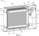
- FIG. 2 illustrates a cross-sectional view of the device 102, according to an embodiment of the present disclosure.
- the device 102 includes the body 108 and an operation chamber 200 coupled to the body 108.
- the water inlet pipe 114 is fluidly connected to a solenoid valve 202 which is configured to regulate the supply of water to the body 108.
- the body 108 houses a water supply manifold 204 located at a top portion thereof and fluidly connected to the solenoid valve 202.
- the solenoid valve 202 regulates the supply of water to the water supply manifold 204.
- the water supply manifold 204 includes a plurality of nozzles 206 extending in a direction inward with respect to the walls of the device 102.
- the device 102 includes a first infinite belt assembly 207 (indicated in FIG. 3A ) disposed along a first plane parallel to a longitudinal plane of the body 108 and a second infinite belt assembly 209 (indicated in FIG. 3A ) disposed along a second plane parallel to the longitudinal plane of the body 108.
- the first infinite belt assembly 207 includes a first set of belt pulleys and a first infinite belt 304 (see FIG. 3A ) extending around an outer circumferential surface of each belt pulley of the first set of belt pulleys.
- the first set of belt pulleys includes a first belt pulley 208 extending along a width of the body 108 and supported at ends thereof by walls of the body 108.
- one end of the first belt pulley 208 is rotatably coupled to a first pulley support 210 and another end of the first belt pulley 208 is operably coupled to a first motor 220.
- a second belt pulley 212 located distant from the first belt pulley 208, as shown in FIG.
- the second belt pulley 212 extends along the width of the body 108 and is supported at ends thereof by the walls of the body 108.
- one end of the second belt pulley 212 is rotatably coupled to a second pulley support 214 and another end is rotatably coupled to the wall of the body 108.
- the second infinite belt assembly 209 includes a second set of belt pulleys (not shown in FIG. 2 ) and a second infinite belt 306 (see FIG. 3A ) extending around an outer circumferential surface of each belt pulley of the second set of belt pulleys.
- Pulley supports 216, 218 correspond to the location of the belt pulleys of the second set of belt pulleys.
- a second motor 222 is operably coupled to one of the belt pulleys of the second set of belt pulleys.
- the term "operably coupled” refers to an arrangement between the motor and the belt pulley that transfers torque from the motor to the belt pulley, thereby causing the belt pulley to rotate about its axis of rotation.
- the axis of rotation of the belt pulleys would be defined by respective end supports thereof at the walls of the body 108.
- the first motor 220 and the second motor 222 together constitute a drive unit for the first set of belt pulleys and the second set of belt pulleys.
- the drive unit is configured to counter rotate the first infinite belt assembly 207 with respect to the second infinite belt assembly 209.
- the first motor 220 is configured to rotate the first set of belt pulleys in a first rotation direction, such as clockwise
- the second motor 222 is configured to rotate the second set of belt pulleys in a second rotation direction, such as anticlockwise.
- the solenoid valve 202 supplies water to the water supply manifold 204, where jets of water are sprayed for cleaning the kitchen tool 106.
- the device 102 further includes a base plate 224 slidably disposed at the base of the body 108.
- the base plate 224 may be selectively slid in a direction along the width of the device 102 and may be selectively detached from the body 108.
- An opening 226 defined in the base plate 224 fluidly connects the body 108 with the outlet pipe 116.
- the base plate 224 may be configured to be accessed when all wash water injected by the nozzles 206 is drained through the opening 226.
- FIG. 3A illustrates a perspective view of a portion of a pair of belt pulleys of the device 102.
- the first belt pulley 208 of the first set of belt pulleys includes multiple teeth at an outer circumferential surface thereof.
- a first belt pulley 302 of the second set of belt pulleys includes multiple teeth at an outer circumferential surface thereof.
- Configuration of other belt pulleys (not shown in FIG. 3A ) of the first set and the second set of belt pulleys are similar to the belt pulleys 208, 306.
- the first infinite belt assembly 207 is positioned proximal to the second infinite belt assembly 209 to define a gap "G" therebetween to receive the kitchen tool 106, such as the cutting board.
- the first infinite belt 304 extends around the first belt pulley 208 and the second belt pulley 212 and the second infinite belt 306 extends around the first belt pulley 302 and a second belt pulley (not shown) of the second set of belt pulleys.
- an inner surface of each infinite belt includes teeth configured to mesh with teeth at the outer circumferential surface of respective belt pulleys. As such, during rotation of the belt pulleys by respective motors, the infinite belts remain secured around the belt pulleys by virtue of the meshing between respective teeth. Additionally, the inner surface of each infinite belt is made of high stiffness material which prevents buckling of the infinite belt.
- each of the first infinite belt 304 and the second infinite belt 306 includes a plurality of bristles 308 extending from respective outer surfaces thereof.
- the bristles 308 are configured to contact the kitchen tool 106, such as the cutting board.
- the bristles 308 are made of one of silicone or ethylene propylene diene monomer rubber, and, hence, are associated with low stiffness. Therefore, the bristles 308 may freely bend during contact with the kitchen tool 106.
- the nozzles 206 are suitably oriented such that the water jet impinges sufficiently on at least one of the infinite belt assemblies, the gap "G", and the kitchen tool 106.
- the bristles 308 clean the surface of the kitchen tool 106 by scrubbing action. Flexibility of the bristles 308 results in easy removal of clutter from the kitchen tool 106 in presence of flowing water. With such configuration, the device 102 may reduce cleaning time and consumption of water.
- FIG. 3B illustrates an enlarged portion "A" of FIG. 3A .
- the infinite belts are designed such that peripheries of the bristles 308 define a zig-zag patten or a wavy pattern as shown in FIG. 3B .
- Such configuration helps to efficiently clean the kitchen tools 106 having arcuate surfaces and multiple cutting edges. Flexibility of the bristles 308 combined with the zig-zag pattern achieves faster and deep cleaning of the kitchen tools 106.
- FIG. 4 illustrates a cross-sectional view of a portion of the device 102.
- the device 102 includes a corrugated portion defined on peripheral internal surfaces of the body 108. At least one of the first infinite belt assembly 207 and the second infinite belt assembly 209 is positioned proximal to the corrugated portion.
- the peripheral internal surface 400 of the body 108 includes the corrugated portion 402 defining a zig-zag pattern.
- the corrugated portion 402 is configured to contact the bristles 308 of the first infinite belt 304.
- Dirt and clutter carried by the bristles 308 may be cleaned from the bristles 308 when the corrugated portion 402 contacts the bristles 308. In the presence of water that is injected onto the infinite belts, cleaning of the bristles 308 may be easier. All the clutter and dirt from the bristles 308 flowing in the downward direction is either drained through the outlet pipe 116 or collected on the base plate 224 which may be cleaned manually by the user after completion of cleaning cycle. It will be understood that an opposite peripheral internal surface of the body 108 may include a similar corrugated portion to help remove dirt and clutter from the bristles 308 of the second infinite belt 306.
- combination of the corrugated portion 402 and the flexibility of the bristles 308 define a self-cleaning mechanism of the device 102 simultaneously with the cleaning of the kitchen tools 106, thus largely reducing consumption of water.
- Such self-cleaning mechanism also eliminates human efforts required to clean the device 102 after each cleaning cycle.
- FIG. 5 illustrates a schematic block diagram of the device 102. Specifically, FIG. 5 will be described in conjunction with FIG. 1-FIG. 4 .
- the device 102 includes a switch 502, such as a limit switch (shown in an OFF condition), electrically connected to a microcontroller 504.
- the switch 502 and the microcontroller 504 may be located in the operation chamber 200 of the device 102.
- the first motor 220 and the second motor 222 are connected to the microcontroller 504 via a first channel 506, and the solenoid valve 202 is connected to the microcontroller 504 via a second channel 508.
- the first channel 506 and the second channel 508 extend parallel from the microcontroller 504. Such parallel connection may help balance the functionality of the device 102, both with respect to cleaning of the kitchen tools 106 and controlling supply of water to the water supply manifold 204.
- the microcontroller 504 may be implemented as a processor, such as one or more microprocessors, microcomputers, digital signal processors, central processing units, state machines, logic circuitries, or any devices that manipulate signals based on operational instructions.
- the processor may be configured to fetch and execute computer-readable instructions stored in a memory thereof.
- Various functions of the processor may be provided using dedicated hardware as well as hardware capable of executing software in association with appropriate software. When provided by the processor, the functions may be provided by a single dedicated processor, by a single shared processor, or by a plurality of individual processors.
- processor should not be construed to refer exclusively to hardware capable of executing software, and may implicitly include, but not limited to, digital signal processor (DSP) hardware, network processor, application specific integrated circuit (ASIC), field programmable gate array (FPGA), read only memory (ROM) for storing software, random access memory (RAM), and non-volatile storage.
- DSP digital signal processor
- ASIC application specific integrated circuit
- FPGA field programmable gate array
- ROM read only memory
- RAM random access memory
- non-volatile storage Other hardware known to a person skilled in the art may also be included.
- actuation of the switch 502 to an ON condition provides electric supply to the microcontroller 504 which is configured to simultaneously actuate the motors 220, 222, and the solenoid valve 202.
- the microcontroller 504 is configured to actuate the first motor 220 to cause the first infinite belt 304 to rotate in the clockwise direction and actuate the second motor 222 to cause rotation of the second infinite belt 306 to rotate in anticlockwise direction.
- the kitchen tool 106 such as the cutting board
- the cutting board is received in the gap "G" and between the bristles 308 of the first infinite belt 304 and the second infinite belt 306.
- the bristles 308 develop a scrubbing action against the surface of the cutting board, thereby removing dirt and substances from the surface. Any clutter present on the surface of the cutting board would be carried by the bristles 308 during movement of the infinite belts. Upon contacting the corrugated portion 402, the clutter and dirt may be discharged from the bristles 308, thereby rendering the bristles 308 clean for subsequent contact with the surface of the cutting board. Due to the large surface area of the infinite belts and rotation speed of the belt pulleys, cleaning of the cutting board may be achieved in short duration. Simultaneously, the microcontroller 504 controls the solenoid valve 202 to supply water to the water supply manifold 204.
- the nozzles 206 inject the jet of water onto at least one of the infinite belts, the kitchen tool 106, and the gap "G", thereby aiding faster cleaning of the cutting board and the bristles 308.
- the switch 502 may be actuated to the OFF condition, where the electrical supply to the microcontroller 504 is ceased.
- electrical supply to the motors 220, 222 and the solenoid valve 202 may be stopped simultaneously.
- the microcontroller 504 may be configured to store a predefined amount of electrical charge, for example, in capacitors thereof, to operate the motors 220, 222 and the solenoid valve 202 for a predefined duration, for example 30 seconds.
- FIG. 6 is an exemplary illustration of implementation of the device 102 into a dishwasher 602, according to an embodiment of the present disclosure.
- the device 102 may be operably disposed within the dishwasher 602. While the dishwasher 602 is used to clean large kitchen utensils, the device 102 can simultaneously clean the kitchen tools 106 at a same location, thereby reducing a total time the user may need to invest in cleaning the kitchen items.
- the infinite belts may be detached, cleaned, and installed back into the device 102.
Landscapes
- Engineering & Computer Science (AREA)
- Water Supply & Treatment (AREA)
- Cleaning By Liquid Or Steam (AREA)
- Cleaning In General (AREA)
- Brushes (AREA)
Abstract
A cleaning device (102) includes a first (207) and a second infinite belt assembly (209) disposed along a first plane and a second plane, respectively, where each plane is parallel to a longitudinal plane of the cleaning device (102). The second infinite belt assembly (209) is disposed proximal to the first infinite belt assembly (207) such that a gap (G) is defined therebetween to receive a kitchen tool (106). Each of the first infinite belt assembly (207) and the second infinite belt assembly (209) includes bristles (308) extending from respective outer surfaces to contact the kitchen tool (106). A water supply manifold (204) of the device (102) supplies water onto at least one of the kitchen tool (106), the infinite belt assemblies (207, 209), and the gap (G). A drive unit counter rotates the first infinite belt assembly (207) with respect to the second infinite belt assembly (209).
Description
- The present disclosure relates, in general, to a cleaning device and, more specifically relates, to a cleaning device used to clean kitchen tools.
- In a commercial or domestic kitchen, time is the essence. Keeping food preparation surfaces and utensils clean and sanitary is often a conflicting goal, since cleaning is a time-consuming task. Multiple kitchen tools are often used in a cooking process, and, hence, there is a need to wash them before and after every use to maintain cleanliness. However, washing of multiple kitchen tools may disturb the flow of other work in the kitchen and may lead to a high water consumption and additional time in the kitchen.
-
Swedish Patent Publication No. 1830122 United Kingdom Patent Publication No. 2459298 U.S. Patent Publication No. 2003/131426 discloses a cleaning container that includes a set of brushes which are actuated to rotary motion when the kitchen tool is inserted into the cleaning container. However, these references fail to disclose features which aid in achieving an efficient cleaning of kitchen tools while providing easy maintenance of the cleaning device and reducing consumption of water. - According to an aspect of the present disclosure, a cleaning device includes a body defining an inlet aperture configured to receive a provided kitchen tool therethrough. The cleaning device further includes a first infinite belt assembly that has a first infinite belt disposed along a first plane and a second infinite belt assembly that has a second infinite belt disposed along a second plane. A gap is between the first infinite belt and the second infinite belt to receive the provided kitchen tool. A water supply manifold is configured to supply water onto at least one of the first infinite belt assembly, the second infinite belt assembly, or the gap. A drive unit is configured to rotate the first infinite belt and the second infinite belt.
- According to another aspect of the present disclosure, a cleaning device includes a body defining an inlet aperture configured to receive a kitchen tool therethrough, a first infinite belt assembly disposed along a first plane parallel to a longitudinal plane of the body and a second infinite belt assembly disposed along a second plane parallel to the longitudinal plane of the body. The second infinite belt assembly is positioned proximal to the first infinite belt assembly and defines a gap therebetween to receive the kitchen tool. Each of the first infinite belt assembly and the second infinite belt assembly includes a plurality of bristles extending from respective outer surfaces to contact the kitchen tool. The cleaning device also includes a water supply manifold to supply water onto at least one of the kitchen tool, the first infinite belt assembly, the second infinite belt assembly, and the gap. A drive unit of the cleaning device counter rotates the first infinite belt assembly with respect to the second infinite belt assembly.
- In an embodiment, the cleaning device includes a corrugated portion defined on peripheral internal surfaces of the body. At least one of the first infinite belt assembly and the second infinite belt assembly is positioned proximal to the corrugated portion such that the corrugated portion contacts the plurality of bristles of the first infinite belt assembly or the second infinite belt assembly during operation of the cleaning device. In an embodiment, the cleaning device further includes a solenoid valve to regulate water supply to the water supply manifold. In an embodiment, the bristles of each of the first infinite belt assembly and the second infinite belt assembly is made of one of silicone or ethylene propylene diene monomer rubber. In an embodiment, the cleaning device is used in a dishwasher.
- The present disclosure provides an improved cleaning device for cleaning kitchen tools. Particularly, the first infinite belt assembly and the second infinite belt assembly offers a large surface area coverage for large spatula or multiple tools in one go. The corrugated portion on the peripheral internal surface of the body provides a self-cleaning mechanism for the cleaning device, where clutter stuck to the bristles are removed when the bristles contact the corrugated portion during rotation of the first infinite belt assembly and the second infinite belt assembly. As such, cleaning of the kitchen tools and cleaning of the bristles are simultaneously performed, thereby largely reducing consumption of water.
- These and other aspects and feature of non-limiting embodiments of the present disclosure will become apparent to those skilled in the art upon review of the following description of specific non-limiting embodiments of the disclosure in conjunction with the accompanying drawings.
- A better understanding of the embodiments of the present disclosure (including alternatives and/or variations thereof) may be obtained with reference to the detailed description of the embodiments along with the following drawings, in which:
-
FIG. 1 is a perspective view of a kitchen countertop implementing a cleaning device; -
FIG. 2 is a cross-sectional view of the cleaning device ofFIG. 1 , according to an embodiment of the present disclosure; -
FIG. 3A is a perspective view of a portion of a pair of belt pulleys of the cleaning device, according to an embodiment of the present disclosure; -
FIG. 3B is an enlarged view of a portion "A" ofFIG. 3A , according to an embodiment of the present disclosure; -
FIG. 4 is a cross-sectional view of a portion of the cleaning device, according to an embodiment of the present disclosure; -
FIG. 5 is a schematic block diagram of the cleaning device, according to an embodiment of the present disclosure; and -
FIG. 6 is an exemplary illustration of implementation of the cleaning device into a dishwasher, according to an embodiment of the present disclosure. - Reference will now be made in detail to specific embodiments or features, examples of which are illustrated in the accompanying drawings. Wherever possible, corresponding, or similar reference numbers, will be used throughout the drawings to refer to the same or corresponding parts. Moreover, references to various elements described herein, are made collectively or individually when there may be more than one element of the same type. However, such references are merely exemplary in nature. It may be noted that any reference to elements in the singular may also be construed to relate to the plural and vice-versa without limiting the scope of the disclosure to the exact number or type of such elements unless set forth explicitly in the appended claims.
- Referring to
FIG. 1 , a perspective view of acountertop 100 implementing a cleaning device 102 (hereinafter referred to as "thedevice 102") is illustrated. Preferably, thedevice 102 is disposed beneath thecountertop 100. Thecountertop 100 defines atool insertion slit 104 that is designed to allow insertion ofkitchen tools 106, such as cutleries, knives, spoons, spatula, cutting board, therethrough, such that an operation portion of thekitchen tools 106 is received within thetool insertion slit 104 while a handle portion of the kitchen tools remains outside thetool insertion slit 104, thereby making it accessible to a user. As used herein, the term "operation portion" refers to a portion of the kitchen tool that is used to execute a function associated with the kitchen tool. For example, a sharp metal portion of the knife may be referred to as the "operation portion" and a portion provided for the user to grip the knife may be referred to as the "handle portion." Further, abody 108 of thedevice 102 defines an inlet aperture (not shown) that is aligned with thetool insertion slit 104, so that the operation portion of thekitchen tools 106 is received into thedevice 102. Awater source 110 provides supply of water to asink 112 and thedevice 102 simultaneously. Particularly, awater inlet pipe 114 extends between thewater source 110 and thedevice 102. Further, anoutlet pipe 116 extends from a base of thedevice 102 to drain dirt and wash water from thedevice 102. -
FIG. 2 illustrates a cross-sectional view of thedevice 102, according to an embodiment of the present disclosure. Thedevice 102 includes thebody 108 and anoperation chamber 200 coupled to thebody 108. Thewater inlet pipe 114 is fluidly connected to asolenoid valve 202 which is configured to regulate the supply of water to thebody 108. - Further, the
body 108 houses awater supply manifold 204 located at a top portion thereof and fluidly connected to thesolenoid valve 202. As such, thesolenoid valve 202 regulates the supply of water to thewater supply manifold 204. Thewater supply manifold 204 includes a plurality ofnozzles 206 extending in a direction inward with respect to the walls of thedevice 102. In an aspect, thedevice 102 includes a first infinite belt assembly 207 (indicated inFIG. 3A ) disposed along a first plane parallel to a longitudinal plane of thebody 108 and a second infinite belt assembly 209 (indicated inFIG. 3A ) disposed along a second plane parallel to the longitudinal plane of thebody 108. The firstinfinite belt assembly 207 includes a first set of belt pulleys and a first infinite belt 304 (seeFIG. 3A ) extending around an outer circumferential surface of each belt pulley of the first set of belt pulleys. The first set of belt pulleys includes afirst belt pulley 208 extending along a width of thebody 108 and supported at ends thereof by walls of thebody 108. For example, one end of thefirst belt pulley 208 is rotatably coupled to afirst pulley support 210 and another end of thefirst belt pulley 208 is operably coupled to afirst motor 220. Similarly, asecond belt pulley 212, located distant from thefirst belt pulley 208, as shown inFIG. 2 , extends along the width of thebody 108 and is supported at ends thereof by the walls of thebody 108. For example, one end of thesecond belt pulley 212 is rotatably coupled to asecond pulley support 214 and another end is rotatably coupled to the wall of thebody 108. - The second
infinite belt assembly 209 includes a second set of belt pulleys (not shown inFIG. 2 ) and a second infinite belt 306 (seeFIG. 3A ) extending around an outer circumferential surface of each belt pulley of the second set of belt pulleys. Pulley supports 216, 218 correspond to the location of the belt pulleys of the second set of belt pulleys. Asecond motor 222 is operably coupled to one of the belt pulleys of the second set of belt pulleys. As used herein, the term "operably coupled" refers to an arrangement between the motor and the belt pulley that transfers torque from the motor to the belt pulley, thereby causing the belt pulley to rotate about its axis of rotation. As would be understood fromFIG. 2 , the axis of rotation of the belt pulleys would be defined by respective end supports thereof at the walls of thebody 108. Thefirst motor 220 and thesecond motor 222 together constitute a drive unit for the first set of belt pulleys and the second set of belt pulleys. Particularly, the drive unit is configured to counter rotate the firstinfinite belt assembly 207 with respect to the secondinfinite belt assembly 209. Preferably, thefirst motor 220 is configured to rotate the first set of belt pulleys in a first rotation direction, such as clockwise, and thesecond motor 222 is configured to rotate the second set of belt pulleys in a second rotation direction, such as anticlockwise. Simultaneously, thesolenoid valve 202 supplies water to thewater supply manifold 204, where jets of water are sprayed for cleaning thekitchen tool 106. - The
device 102 further includes abase plate 224 slidably disposed at the base of thebody 108. Thebase plate 224 may be selectively slid in a direction along the width of thedevice 102 and may be selectively detached from thebody 108. Anopening 226 defined in thebase plate 224 fluidly connects thebody 108 with theoutlet pipe 116. Preferably, thebase plate 224 may be configured to be accessed when all wash water injected by thenozzles 206 is drained through theopening 226. -
FIG. 3A illustrates a perspective view of a portion of a pair of belt pulleys of thedevice 102. Thefirst belt pulley 208 of the first set of belt pulleys includes multiple teeth at an outer circumferential surface thereof. Similarly, afirst belt pulley 302 of the second set of belt pulleys includes multiple teeth at an outer circumferential surface thereof. Configuration of other belt pulleys (not shown inFIG. 3A ) of the first set and the second set of belt pulleys are similar to the belt pulleys 208, 306. Advantageously, the firstinfinite belt assembly 207 is positioned proximal to the secondinfinite belt assembly 209 to define a gap "G" therebetween to receive thekitchen tool 106, such as the cutting board. - The first
infinite belt 304 extends around thefirst belt pulley 208 and thesecond belt pulley 212 and the secondinfinite belt 306 extends around thefirst belt pulley 302 and a second belt pulley (not shown) of the second set of belt pulleys. As seen inFIG. 3A , an inner surface of each infinite belt includes teeth configured to mesh with teeth at the outer circumferential surface of respective belt pulleys. As such, during rotation of the belt pulleys by respective motors, the infinite belts remain secured around the belt pulleys by virtue of the meshing between respective teeth. Additionally, the inner surface of each infinite belt is made of high stiffness material which prevents buckling of the infinite belt. - Advantageously, each of the first
infinite belt 304 and the secondinfinite belt 306 includes a plurality ofbristles 308 extending from respective outer surfaces thereof. Thebristles 308 are configured to contact thekitchen tool 106, such as the cutting board. In an embodiment, thebristles 308 are made of one of silicone or ethylene propylene diene monomer rubber, and, hence, are associated with low stiffness. Therefore, thebristles 308 may freely bend during contact with thekitchen tool 106. Further, thenozzles 206 are suitably oriented such that the water jet impinges sufficiently on at least one of the infinite belt assemblies, the gap "G", and thekitchen tool 106. During cleaning of thekitchen tool 106, thebristles 308 clean the surface of thekitchen tool 106 by scrubbing action. Flexibility of thebristles 308 results in easy removal of clutter from thekitchen tool 106 in presence of flowing water. With such configuration, thedevice 102 may reduce cleaning time and consumption of water. -
FIG. 3B illustrates an enlarged portion "A" ofFIG. 3A . The infinite belts are designed such that peripheries of thebristles 308 define a zig-zag patten or a wavy pattern as shown inFIG. 3B . Such configuration helps to efficiently clean thekitchen tools 106 having arcuate surfaces and multiple cutting edges. Flexibility of thebristles 308 combined with the zig-zag pattern achieves faster and deep cleaning of thekitchen tools 106. -
FIG. 4 illustrates a cross-sectional view of a portion of thedevice 102. In an advantageous embodiment, thedevice 102 includes a corrugated portion defined on peripheral internal surfaces of thebody 108. At least one of the firstinfinite belt assembly 207 and the secondinfinite belt assembly 209 is positioned proximal to the corrugated portion. In the illustrated embodiment, the peripheralinternal surface 400 of thebody 108 includes thecorrugated portion 402 defining a zig-zag pattern. During operation of thedevice 102, particularly during rotation of the first set of belt pulleys, thecorrugated portion 402 is configured to contact thebristles 308 of the firstinfinite belt 304. Dirt and clutter carried by thebristles 308 may be cleaned from thebristles 308 when thecorrugated portion 402 contacts thebristles 308. In the presence of water that is injected onto the infinite belts, cleaning of thebristles 308 may be easier. All the clutter and dirt from thebristles 308 flowing in the downward direction is either drained through theoutlet pipe 116 or collected on thebase plate 224 which may be cleaned manually by the user after completion of cleaning cycle. It will be understood that an opposite peripheral internal surface of thebody 108 may include a similar corrugated portion to help remove dirt and clutter from thebristles 308 of the secondinfinite belt 306. Therefore, combination of thecorrugated portion 402 and the flexibility of thebristles 308 define a self-cleaning mechanism of thedevice 102 simultaneously with the cleaning of thekitchen tools 106, thus largely reducing consumption of water. Such self-cleaning mechanism also eliminates human efforts required to clean thedevice 102 after each cleaning cycle. -
FIG. 5 illustrates a schematic block diagram of thedevice 102. Specifically,FIG. 5 will be described in conjunction withFIG. 1-FIG. 4 . In an embodiment, thedevice 102 includes aswitch 502, such as a limit switch (shown in an OFF condition), electrically connected to amicrocontroller 504. Theswitch 502 and themicrocontroller 504 may be located in theoperation chamber 200 of thedevice 102. Thefirst motor 220 and thesecond motor 222 are connected to themicrocontroller 504 via afirst channel 506, and thesolenoid valve 202 is connected to themicrocontroller 504 via asecond channel 508. As seen inFIG. 5 , thefirst channel 506 and thesecond channel 508 extend parallel from themicrocontroller 504. Such parallel connection may help balance the functionality of thedevice 102, both with respect to cleaning of thekitchen tools 106 and controlling supply of water to thewater supply manifold 204. - In some embodiments, the
microcontroller 504 may be implemented as a processor, such as one or more microprocessors, microcomputers, digital signal processors, central processing units, state machines, logic circuitries, or any devices that manipulate signals based on operational instructions. Among other capabilities the processor may be configured to fetch and execute computer-readable instructions stored in a memory thereof. Various functions of the processor may be provided using dedicated hardware as well as hardware capable of executing software in association with appropriate software. When provided by the processor, the functions may be provided by a single dedicated processor, by a single shared processor, or by a plurality of individual processors. Moreover, explicit use of the term "processor" should not be construed to refer exclusively to hardware capable of executing software, and may implicitly include, but not limited to, digital signal processor (DSP) hardware, network processor, application specific integrated circuit (ASIC), field programmable gate array (FPGA), read only memory (ROM) for storing software, random access memory (RAM), and non-volatile storage. Other hardware known to a person skilled in the art may also be included. - In operation, actuation of the
switch 502 to an ON condition provides electric supply to themicrocontroller 504 which is configured to simultaneously actuate themotors solenoid valve 202. Themicrocontroller 504 is configured to actuate thefirst motor 220 to cause the firstinfinite belt 304 to rotate in the clockwise direction and actuate thesecond motor 222 to cause rotation of the secondinfinite belt 306 to rotate in anticlockwise direction. When thekitchen tool 106, such as the cutting board, is inserted through the tool insertion slit 104 defined in thecountertop 100, the cutting board is received in the gap "G" and between thebristles 308 of the firstinfinite belt 304 and the secondinfinite belt 306. By virtue of the flexibility, thebristles 308 develop a scrubbing action against the surface of the cutting board, thereby removing dirt and substances from the surface. Any clutter present on the surface of the cutting board would be carried by thebristles 308 during movement of the infinite belts. Upon contacting thecorrugated portion 402, the clutter and dirt may be discharged from thebristles 308, thereby rendering thebristles 308 clean for subsequent contact with the surface of the cutting board. Due to the large surface area of the infinite belts and rotation speed of the belt pulleys, cleaning of the cutting board may be achieved in short duration. Simultaneously, themicrocontroller 504 controls thesolenoid valve 202 to supply water to thewater supply manifold 204. Thenozzles 206 inject the jet of water onto at least one of the infinite belts, thekitchen tool 106, and the gap "G", thereby aiding faster cleaning of the cutting board and thebristles 308. Upon completion of the cleaning cycle, theswitch 502 may be actuated to the OFF condition, where the electrical supply to themicrocontroller 504 is ceased. As such, electrical supply to themotors solenoid valve 202 may be stopped simultaneously. In some embodiments, themicrocontroller 504 may be configured to store a predefined amount of electrical charge, for example, in capacitors thereof, to operate themotors solenoid valve 202 for a predefined duration, for example 30 seconds. During such operation of thesolenoid valve 202, water may be injected onto the infinite belts to remove any further remains of clutter or dirt from thebristles 308. Such operation helps to keep thedevice 102 ready for subsequent cleaning cycles. On completion of the predefined duration, themotors solenoid valve 202 are stopped. -
FIG. 6 is an exemplary illustration of implementation of thedevice 102 into adishwasher 602, according to an embodiment of the present disclosure. Thedevice 102 may be operably disposed within thedishwasher 602. While thedishwasher 602 is used to clean large kitchen utensils, thedevice 102 can simultaneously clean thekitchen tools 106 at a same location, thereby reducing a total time the user may need to invest in cleaning the kitchen items. In some embodiments, the infinite belts may be detached, cleaned, and installed back into thedevice 102. - While aspects of the present disclosure have been particularly shown and described with reference to the embodiments above, it will be understood by those skilled in the art that various additional embodiments may be contemplated by the modification of the disclosed methods without departing from the spirit and scope of what is disclosed. Such embodiments should be understood to fall within the scope of the present disclosure as determined based upon the claims and any equivalents thereof.
Claims (15)
- A cleaning device (102) comprising:a body (108) defining an inlet aperture configured to receive a provided kitchen tool (106) therethrough;a first infinite belt assembly (207) including a first infinite belt (304) disposed along a first plane;a second infinite belt assembly (209) including a second infinite belt (306) disposed along a second plane;a gap (G) between the first infinite belt (304) and the second infinite belt (306) to receive the provided kitchen tool (106);a water supply manifold (204) configured to supply water onto at least one of the first infinite belt assembly (207), the second infinite belt assembly (209), or the gap (G); anda drive unit configured to rotate the first infinite belt (304) and the second infinite belt (306).
- The cleaning device (102) of claim 1, wherein the first infinite belt (304) and the second infinite belt (306) each include an outer surface including a plurality of bristles (308) that move through the gap (G) upon a rotation of the first infinite belt (304) and the second infinite belt (306).
- The cleaning device (102) of either one of claims 1 or 2, wherein the drive unit is further configured to rotate the first infinite belt (304) in a first direction and rotate and the second infinite belt (306) in a second direction that is counter to the first direction.
- The cleaning device (102) of any one of claims 1-3, wherein the drive unit includes a first motor (220) driving the first infinite belt (304) and a second motor (222) driving the second infinite belt (306).
- The cleaning device (102) of any one of claims 1-4, wherein the first infinite belt assembly (207) includes a first pair of belt pulleys (208, 212) and the first infinite belt (304) extends around and is engaged with the first pair of belt pulleys (208, 212), and wherein the second infinite belt assembly (209) includes a second pair of belt pulleys (302) and the second infinite belt (306) extends around and is engaged with the second pair of belt pulleys (302).
- The cleaning device (102) of claim 5, wherein the first motor (220) is operably coupled with one of the first pair of belt pulleys (208, 212) and the second motor (222) is operably coupled with one of the second pair of belt pulleys (302).
- The cleaning device (102) of either one of claims 5 or 6, wherein each of the first pair of belt pulleys (208, 212) includes multiple teeth at an outer circumferential surface thereof and each of the second pair of belt pulleys (302) includes multiple teeth at an outer circumferential surface thereof.
- The cleaning device (102) of claim 7, wherein the first infinite belt (304) and the second infinite belt (306) each include teeth configured to mesh with the multiple teeth at the outer circumferential surface of respective belt pulleys (208, 212, 302).
- The cleaning device (102) of any one of claims 2-8, further comprising a corrugated portion (402) defined on a peripheral internal surface of the body (108), wherein at least one of the first infinite belt assembly (207) and the second infinite belt assembly (209) is positioned proximal to the corrugated portion (402) to contact the plurality of bristles (308) of the first infinite belt (304) or the second infinite belt (306) during rotation.
- The cleaning device (102) of claim 9, wherein the corrugated portion (402) is defined on a pair of peripheral internal surfaces of the body (108) to contact the plurality of bristles (308) of the first infinite belt (304) and the second infinite belt (306) during rotation, respectively.
- The cleaning device (102) of any one of claims 1-10, further comprising a solenoid valve (202) configured to regulate water supply to the water supply manifold (204).
- The cleaning device (102) of any one of claims 2-11, wherein the plurality of bristles (308) are made of one of silicone or ethylene propylene diene monomer rubber.
- The cleaning device (102) of any one of claims 1-12, further comprising a base plate (224) slidably disposed at a base of the body (108) to facilitate cleaning.
- The cleaning device (102) of claim 13, wherein the base plate (224) defines an opening (226) configured to be fluidically connected to an outlet pipe (116).
- A dishwasher (602) comprising the cleaning device (102) of any one of claims 1-14.
Applications Claiming Priority (1)
| Application Number | Priority Date | Filing Date | Title |
|---|---|---|---|
| US17/584,874 US11857132B2 (en) | 2022-01-26 | 2022-01-26 | Cleaning device |
Publications (1)
| Publication Number | Publication Date |
|---|---|
| EP4218528A1 true EP4218528A1 (en) | 2023-08-02 |
Family
ID=85132838
Family Applications (1)
| Application Number | Title | Priority Date | Filing Date |
|---|---|---|---|
| EP23153566.7A Withdrawn EP4218528A1 (en) | 2022-01-26 | 2023-01-26 | Cleaning device |
Country Status (2)
| Country | Link |
|---|---|
| US (1) | US11857132B2 (en) |
| EP (1) | EP4218528A1 (en) |
Citations (6)
| Publication number | Priority date | Publication date | Assignee | Title |
|---|---|---|---|---|
| US20030131426A1 (en) | 1996-01-25 | 2003-07-17 | Christof Schulling | Cleaning device for individual items of cutlery |
| GB2459298A (en) | 2008-04-18 | 2009-10-21 | Robert James Newman | Instant cutlery cleaner |
| CN108742438A (en) * | 2018-05-31 | 2018-11-06 | 江山宏力产品设计有限公司 | A kind of kitchen utensils |
| SE1830122A1 (en) | 2018-04-13 | 2019-10-14 | Electrolux Appliances AB | Instant dishwasher |
| CN111904354A (en) * | 2020-07-30 | 2020-11-10 | 广州富港万嘉智能科技有限公司 | Tableware cleaning machine |
| CN113854921A (en) * | 2021-09-29 | 2021-12-31 | 吴宗万 | Chopstick cleaning machine with high cleaning degree |
Family Cites Families (9)
| Publication number | Priority date | Publication date | Assignee | Title |
|---|---|---|---|---|
| US5581836A (en) * | 1995-02-21 | 1996-12-10 | Kleber; Richard M. | Compact washing unit and method of washing and sanitizing trays |
| WO2006030472A1 (en) | 2004-09-13 | 2006-03-23 | Matteo Rovetta | Washing device for kitchenware |
| US7455067B1 (en) * | 2005-01-13 | 2008-11-25 | Cotton Randall D | Portable food tray pre-wash and water recycling apparatus |
| KR101281449B1 (en) * | 2011-09-09 | 2013-07-03 | 주식회사 텍콤 | Washing up Machine Having Cylindrical Type Rotating Brush |
| US9560952B2 (en) | 2014-03-01 | 2017-02-07 | Sani-Blade, Llc | Utensil cleaning device and method |
| GB2548067A (en) | 2015-01-27 | 2017-09-13 | Jones Rosemary | A cutlery washing up design |
| US20190116969A1 (en) * | 2016-07-15 | 2019-04-25 | Elle Leary | Brush cleaning device |
| CN114403741B (en) | 2017-03-10 | 2024-02-27 | 尚科宁家运营有限公司 | Blender with cleaner and hair removal |
| KR20200016462A (en) | 2018-08-07 | 2020-02-17 | (주)한소닉 | Roller brush apparatus for meal utensil automatic washing of dish washer |
-
2022
- 2022-01-26 US US17/584,874 patent/US11857132B2/en active Active
-
2023
- 2023-01-26 EP EP23153566.7A patent/EP4218528A1/en not_active Withdrawn
Patent Citations (6)
| Publication number | Priority date | Publication date | Assignee | Title |
|---|---|---|---|---|
| US20030131426A1 (en) | 1996-01-25 | 2003-07-17 | Christof Schulling | Cleaning device for individual items of cutlery |
| GB2459298A (en) | 2008-04-18 | 2009-10-21 | Robert James Newman | Instant cutlery cleaner |
| SE1830122A1 (en) | 2018-04-13 | 2019-10-14 | Electrolux Appliances AB | Instant dishwasher |
| CN108742438A (en) * | 2018-05-31 | 2018-11-06 | 江山宏力产品设计有限公司 | A kind of kitchen utensils |
| CN111904354A (en) * | 2020-07-30 | 2020-11-10 | 广州富港万嘉智能科技有限公司 | Tableware cleaning machine |
| CN113854921A (en) * | 2021-09-29 | 2021-12-31 | 吴宗万 | Chopstick cleaning machine with high cleaning degree |
Also Published As
| Publication number | Publication date |
|---|---|
| US20230233050A1 (en) | 2023-07-27 |
| US11857132B2 (en) | 2024-01-02 |
Similar Documents
| Publication | Publication Date | Title |
|---|---|---|
| CN113812833A (en) | Cooking device, device with self-cleaning function, accessory and self-cleaning method | |
| TW548089B (en) | Washing machine | |
| EP2126181B1 (en) | A washing machine | |
| CN107157419A (en) | The cleaning of ultrasound wave barrel formula, drying, sterilization, buffet all-in-one | |
| CN110537886A (en) | Brushing type automatic dish-washing machine | |
| EP3785596B1 (en) | A dishwasher comprising a fruit and vegetable washing apparatus | |
| US11857132B2 (en) | Cleaning device | |
| CN106037606B (en) | One kind washing service plate machine | |
| KR101281449B1 (en) | Washing up Machine Having Cylindrical Type Rotating Brush | |
| CN220713859U (en) | Cleaning components and dishwashers | |
| CN113598681A (en) | Scrubbing type bowl washing device and using method | |
| JP2025010306A (en) | Control Method | |
| US2022220A (en) | Dishwashing machine | |
| CN108634896A (en) | A kind of new type ultrasonic water basin dish-washing machine | |
| CN113208408A (en) | Cooking device, device with self-cleaning function, accessory and self-cleaning method | |
| KR200326663Y1 (en) | Dish washing machine with a waste water auto drain function | |
| KR20080011995A (en) | Cutlery Washer | |
| CN221083571U (en) | All-round spray arm | |
| CN209733914U (en) | Integrated water tank in dish washing machine | |
| US2909799A (en) | Cleaning and scouring device | |
| CN214048725U (en) | Cutter belt cleaning device is used in cooked food processing of roast lamb leg | |
| KR102011217B1 (en) | Apparatus for washing the dishes for sink | |
| AU2008234974B2 (en) | Cutlery Cleaner | |
| TWI291341B (en) | Dishwasher | |
| CN209661570U (en) | Dishwasher gadget box |
Legal Events
| Date | Code | Title | Description |
|---|---|---|---|
| PUAI | Public reference made under article 153(3) epc to a published international application that has entered the european phase |
Free format text: ORIGINAL CODE: 0009012 |
|
| STAA | Information on the status of an ep patent application or granted ep patent |
Free format text: STATUS: THE APPLICATION HAS BEEN PUBLISHED |
|
| AK | Designated contracting states |
Kind code of ref document: A1 Designated state(s): AL AT BE BG CH CY CZ DE DK EE ES FI FR GB GR HR HU IE IS IT LI LT LU LV MC ME MK MT NL NO PL PT RO RS SE SI SK SM TR |
|
| STAA | Information on the status of an ep patent application or granted ep patent |
Free format text: STATUS: THE APPLICATION IS DEEMED TO BE WITHDRAWN |
|
| 18D | Application deemed to be withdrawn |
Effective date: 20240203 |