EP4218397A1 - Variable geometry windguard - Google Patents
Variable geometry windguard Download PDFInfo
- Publication number
- EP4218397A1 EP4218397A1 EP23153957.8A EP23153957A EP4218397A1 EP 4218397 A1 EP4218397 A1 EP 4218397A1 EP 23153957 A EP23153957 A EP 23153957A EP 4218397 A1 EP4218397 A1 EP 4218397A1
- Authority
- EP
- European Patent Office
- Prior art keywords
- arm
- assembly
- windguard
- baler
- crop material
- Prior art date
- Legal status (The legal status is an assumption and is not a legal conclusion. Google has not performed a legal analysis and makes no representation as to the accuracy of the status listed.)
- Pending
Links
- 239000000463 material Substances 0.000 claims abstract description 140
- 238000000034 method Methods 0.000 claims description 15
- 230000000284 resting effect Effects 0.000 description 9
- 238000003466 welding Methods 0.000 description 7
- 230000006870 function Effects 0.000 description 6
- 229910000831 Steel Inorganic materials 0.000 description 5
- 239000012530 fluid Substances 0.000 description 5
- 239000004459 forage Substances 0.000 description 5
- 239000010959 steel Substances 0.000 description 5
- 229920000049 Carbon (fiber) Polymers 0.000 description 4
- 239000004917 carbon fiber Substances 0.000 description 4
- 238000001746 injection moulding Methods 0.000 description 4
- 239000002184 metal Substances 0.000 description 4
- VNWKTOKETHGBQD-UHFFFAOYSA-N methane Chemical compound C VNWKTOKETHGBQD-UHFFFAOYSA-N 0.000 description 4
- 230000003287 optical effect Effects 0.000 description 4
- 229920005594 polymer fiber Polymers 0.000 description 4
- 230000005540 biological transmission Effects 0.000 description 3
- 238000004891 communication Methods 0.000 description 2
- 238000010586 diagram Methods 0.000 description 2
- 238000003306 harvesting Methods 0.000 description 2
- 238000012423 maintenance Methods 0.000 description 2
- 238000003860 storage Methods 0.000 description 2
- 238000011144 upstream manufacturing Methods 0.000 description 2
- 238000013528 artificial neural network Methods 0.000 description 1
- 230000000712 assembly Effects 0.000 description 1
- 238000000429 assembly Methods 0.000 description 1
- 230000004888 barrier function Effects 0.000 description 1
- 238000004364 calculation method Methods 0.000 description 1
- 230000001413 cellular effect Effects 0.000 description 1
- 238000010276 construction Methods 0.000 description 1
- 230000001419 dependent effect Effects 0.000 description 1
- 239000000428 dust Substances 0.000 description 1
- 229920002457 flexible plastic Polymers 0.000 description 1
- 238000007667 floating Methods 0.000 description 1
- 210000000245 forearm Anatomy 0.000 description 1
- 239000010720 hydraulic oil Substances 0.000 description 1
- 230000002452 interceptive effect Effects 0.000 description 1
- 229920003023 plastic Polymers 0.000 description 1
- 229920000642 polymer Polymers 0.000 description 1
- 239000002689 soil Substances 0.000 description 1
Images


Classifications
-
- A—HUMAN NECESSITIES
- A01—AGRICULTURE; FORESTRY; ANIMAL HUSBANDRY; HUNTING; TRAPPING; FISHING
- A01D—HARVESTING; MOWING
- A01D89/00—Pick-ups for loaders, chaff-cutters, balers, field-threshers, or the like, i.e. attachments for picking-up hay or the like field crops
- A01D89/006—Accessories
- A01D89/008—Devices cooperating with the pick-up
-
- A—HUMAN NECESSITIES
- A01—AGRICULTURE; FORESTRY; ANIMAL HUSBANDRY; HUNTING; TRAPPING; FISHING
- A01F—PROCESSING OF HARVESTED PRODUCE; HAY OR STRAW PRESSES; DEVICES FOR STORING AGRICULTURAL OR HORTICULTURAL PRODUCE
- A01F15/00—Baling presses for straw, hay or the like
- A01F15/08—Details
- A01F15/10—Feeding devices for the crop material e.g. precompression devices
- A01F15/106—Feeding devices for the crop material e.g. precompression devices for round balers
-
- A—HUMAN NECESSITIES
- A01—AGRICULTURE; FORESTRY; ANIMAL HUSBANDRY; HUNTING; TRAPPING; FISHING
- A01F—PROCESSING OF HARVESTED PRODUCE; HAY OR STRAW PRESSES; DEVICES FOR STORING AGRICULTURAL OR HORTICULTURAL PRODUCE
- A01F15/00—Baling presses for straw, hay or the like
- A01F15/07—Rotobalers, i.e. machines for forming cylindrical bales by winding and pressing
-
- A—HUMAN NECESSITIES
- A01—AGRICULTURE; FORESTRY; ANIMAL HUSBANDRY; HUNTING; TRAPPING; FISHING
- A01F—PROCESSING OF HARVESTED PRODUCE; HAY OR STRAW PRESSES; DEVICES FOR STORING AGRICULTURAL OR HORTICULTURAL PRODUCE
- A01F15/00—Baling presses for straw, hay or the like
- A01F15/08—Details
- A01F15/10—Feeding devices for the crop material e.g. precompression devices
- A01F2015/107—Means for withdrawing knives, rotor or walls of the feeding chamber in case of plugging or congestion
Definitions
- the present invention pertains to an agricultural baler, and, more specifically, to a windguard assembly of the agricultural baler.
- Agricultural harvesting machines such as agricultural balers (which can be referred to as balers), have been used to consolidate and package crop material (which can also be referred to as forage, forage material, or forage crop material) so as to facilitate the storage and handling of the crop material for later use.
- a mower-conditioner cuts and conditions the crop material and forms it into a swath or windrow to dry in the sun.
- an agricultural harvesting machine such as an agricultural baler, travels along the swath or windrows (hereinafter, collectively referred to as windrows, unless otherwise specified) to pick up the crop material.
- Agricultural balers can be, for example, round balers, large square balers, and small square balers, which form the bales into corresponding shapes, as is known.
- pickups of the baler gather the cut and windrowed crop material from the ground, and then convey the cut crop material toward a bale-forming chamber within the baler (that is, the bale chamber).
- a drive mechanism operates to activate any pickups of a pickup assembly, augers, and/or a rotor (which can be referred to as a feeder) of a rotary feeder assembly of a feeder system.
- a pickup can convey crop material in an overshot manner, while a rotor can convey crop material toward or into the bale chamber in an undershot manner.
- a conventional bale chamber of a round baler may include a pair of opposing sidewalls with a series of rolls (which can be referred to as rollers) and belts that rotate and compress the crop material into a cylindrical shape.
- a wrapping assembly which includes wrap material, may wrap the bale to ensure, at least in part, that the bale maintains its shape and density.
- the wrap material can include a film (such as a flexible plastic wrap) or a net (which can be referred to as net wrap).
- wrap material may be used to wrap the bale of crop material.
- a cutting or severing mechanism of the wrapping assembly may be used to cut the wrap material once the bale has been wrapped.
- the wrapped bale may be ejected from the baler and onto the ground by, for example, raising a tailgate of the baler. The tailgate is then closed, and the cycle repeated as necessary and desired to manage the field of cut crop material.
- the feeder system can include not only the pickup assembly and the rotor assembly, for example, but also a floor, a cutting assembly, and a windguard assembly.
- the pickup includes a plurality of tines to pick up the crop material disposed in a windrow.
- the rotor which is downstream of the pickup, can be positioned above the floor which the crop material traverses prior to entering the bale chamber and can work in conjunction with, and cooperatively with, the cutting assembly.
- the rotor can include a rotor shaft (extending transversely) and a plurality of tines (which can have a generally triangular or star-shaped configuration) spaced apart across the transverse extent of the baler.
- the tines are configured to engage and thereby to push the crop material towards the bale chamber and can be grouped in pairs, with a relatively short distance between the tines of a given pair.
- the floor can include a plurality of slots across the transverse extent of the floor, each slot extending longitudinally in the floor (that is, parallel or otherwise aligned with a direction of crop flow).
- the cutting assembly can include a plurality of knives (which can also be referred to as cutters) which are selectively received in the slots of this floor, respectively. When inserted through the slots so that the knives extend at least partially above the floor, each respective knife (depending upon the design) can extend between a pair of tines of the rotor, as the rotor shaft rotates the tines.
- the knives as they extend through the slots above the floor are configured to cut the crop material to a predetermined length, as the crop material passes by the knives prior to the crop material entering the bale chamber. These knives can be configured to drop at least partially below the floor upon being struck by a foreign object.
- the windguard assembly can include a roller and a plurality of tines extending aft and can be configured to retain the crop material along at least a part of its flow path as it proceeds rearward by the pickup and the rotor to the bale chamber and, in so doing, can be positioned adjacent to an upper portion of the crop material. Further, the windguard assembly can be pivotably attached to the pickup assembly.
- the crop material becomes plugged in the feeder system. That is, the crop material bunches up so as to form a plug of crop material (which can be referred to as a crop plug), which does not allow, or otherwise at least partially inhibits, the crop material from flowing from the feeder system into the bale chamber.
- Round balers prone to plugging can have a variable position (drop) floor below the rotor (also known as the feeder) that allows the crop plug to be passed, by increasing a space between the floor and the rotor.
- a drop floor can be effective in unplugging if only the rotor is plugged but often is not effective for unplugging when the crop material is plugged between the windguard assembly and the pickup (resulting in a pickup plug).
- Such a plug can result, for example, when an operator's ground speed has exceeded the feeding capacity of the baler.
- a plug of crop material occurs that cannot be cleared by the drop floor, some operators may use a manually or remotely operated rotor reverser of a reversing system (so as to reverse a direction of the flow of the crop material), which can be useful in loosening the crop material but typically is unable to clear a pickup entirely.
- the reversing system cannot effectively clear a pickup plug because a conventional construction of windguard assembly geometry acts as a barrier, preventing the flow of the crop material in the reverse direction. For, the tines of the windguard assembly act as barbs, jamming the crop material and thus stopping the reverse flow of crop material and preventing the crop from clearing.
- the present invention provides an agricultural baler with a feeder system including a windguard assembly configured for selectively moving between a plurality of positions, such that a plug of crop material can be removed from the feeder system when the flow direction of the crop material in the feeder system is reversed.
- the invention in one form is directed to a windguard assembly of a feeder system of an agricultural baler, the agricultural baler including a baler frame, the feeder system being coupled with the baler frame, the windguard assembly including: the windguard assembly, which is configured for selectively occupying a first position and a second position, the first position being associated with a normal flow direction of a crop material relative to the feeder system, the second position being associated with a reversal of the normal flow direction of the crop material.
- the invention in another form is directed to an agricultural machine, including: a machine frame; and a feeder system coupled with the machine frame and including a windguard assembly, the windguard assembly being configured for selectively occupying a first position and a second position, the first position being associated with a normal flow direction of a crop material relative to the feeder system, the second position being associated with a reversal of the normal flow direction of the crop material.
- the invention in yet another form is directed to a method of using an agricultural baler, the method including the steps of: providing a baler frame and a feeder system, the feeder system being coupled with the baler frame and including a windguard assembly; occupying selectively, by the windguard assembly, a first position, the first position being associated with a normal flow direction of a crop material relative to the feeder system; and occupying selectively, by the windguard assembly, a second position, the second position being associated with a reversal of the normal flow direction of the crop material.
- An advantage of the present invention is that it provides a windguard design of variable geometry for use with a harvester pickup to allow effective rejection of a crop plug from the machine.
- Another advantage is that it provides that, in varying the geometry of the windguard, the windguard, or at least a portion thereof, can be extended forward to open up space for the crop plug to be removed.
- Yet another advantage is that it provides that, in varying the geometry of the windguard, the tines of the windguard can be pivoted so that they do not act as barbs when the plug is attempted to be removed.
- windguard assembly does not need to be removed in order to remove a crop plug.
- a variation of the geometry of the windguard assembly can be controlled by a controller, based upon sensor feedback, in order to optimize crop feeding.
- the variation of the geometry of the windguard assembly can be controlled by a user.
- forward when used in connection with the agricultural vehicle, agricultural baler, and/or components thereof are usually determined with reference to the direction of forward operative travel of the agricultural vehicle and/or agricultural baler, but they should not be construed as limiting.
- longitudinal and transverse are determined with reference to the fore-and-aft direction of the agricultural vehicle and/or agricultural baler and are equally not to be construed as limiting.
- downstream and upstream are determined with reference to the intended direction of crop material flow during operation, with “downstream” being analogous to "rearward” and “upstream” being analogous to "forward.”
- FIG. 1 there is shown an embodiment of an agricultural vehicle 100 (which can be referred to as a work vehicle 100) towing an agricultural baler 101 (any baler herein can be referred to as an agricultural machine), in accordance with the present invention, to perform a baling operation within a field
- work vehicle 100 can be configured as an agricultural tractor, such as an operator-driven tractor or an autonomous tractor.
- the work vehicle 100 may correspond to any other suitable vehicle configured to tow a baler across a field or that is otherwise configured to facilitate the performance of a baling operation, including an autonomous baling vehicle.
- baler 101 can configured as a round baler configured to generate round bales.
- baler 101 may have any other suitable configuration, including being configured to generate square or rectangular bales.
- baler 101 while shown as being towed by tractor 100, may also be a self-propelled baler that does not rely on a separate vehicle for propulsion and/or power to function. While the present invention is described with respect to a baler, it can be appreciated that other the present invention can be used in conjunction with other agricultural machines, such as vehicles and/or implements, such as a self-loading forage wagon.
- Work vehicle 100 includes a pair of front wheels 102, a pair of rear wheels 103, and a chassis 104 coupled to and supported by the wheels 102, 103.
- An operator's cab 105 may be supported by a portion of the chassis 104 and may house various input devices for permitting an operator to control the operation of work vehicle 100 and/or baler 101.
- work vehicle 100 may include an engine and a transmission mounted on chassis 104. The transmission may be operably coupled to the engine and may provide variably adjusted gear ratios for transferring engine power to wheels 103 via a drive axle assembly.
- baler 101 may be coupled to baler 101 via a power take-off (PTO) 106 and a tongue 107 to a hitch of work vehicle 100 to allow vehicle 100 to tow baler 101 across the field.
- PTO power take-off
- work vehicle 100 may, for example, guide baler 101 toward crop material 136 deposited in windrows on the field.
- baler 101 includes a feeder system 108 (which can be referred to generally as a crop collector) mounted on a front end of baler 101.
- Feeder system 108 may, for example, include a pickup assembly 111, a rotary feeder assembly 121, a floor 131, and a windguard assembly 128.
- Pickup assembly 111 includes a rotating wheel with tines that collect crop material 136 from the ground and direct crop material 136 toward a bale chamber 109 of baler 101 in an overshot manner (rotating clockwise in FIG. 1 ).
- Rotary feeder assembly 121 includes a rotating shaft (rotor shaft) and a plurality of rotor devices 144 (which can be referred to as rotors 144) mounted to the shaft so as to rotate about the shaft in a counter-clockwise manner (as seen in FIG. 1 and shown by arrow 134), rotors 144 configured to push or otherwise to move crop material 136 towards or into bale chamber 109, in an undershot manner.
- Feeder system 108 can also include a rotating shaft (not shown in FIG.
- FIG. 1 shows crop material 136 lying in a windrow on the ground of the field and being picked up by pickup assembly 111 of feeder system 108. Upon being picked up, crop material flow 136 flows over pickup assembly 111, under windguard assembly 128, and under rotary feeder assembly 121, as indicated by arrow 132. Arrow 132 thus indicates the normal flow direction 132 of crop material 136 relative to feeder system 108.
- FIG. 1 shows baler 101 schematically and thus with one pair of wheels, though it can be appreciated that baler 101 can include one or more additional pair of wheels, as in FIG. 2 .
- bale 110 is contained within baler 101 until ejection of bale 110 is instructed (e.g., by the operator and/or a baler controller 123 of baler 101). In some embodiments, bale 110 may be automatically ejected from baler 101 once bale 110 is formed, by baler controller 123 detecting that bale 110 is fully formed and outputting an appropriate ejection signal.
- work vehicle 100 includes a control system 114, which includes a controller 115, which includes a processor 116, memory 117, data 118, and instructions 119.
- Control system 114 can further include an input/output device 120 such as a laptop computer (with keyboard and display) or a touchpad (including keypad functionality and a display), device 120 being configured for a user to interface therewith.
- baler 101 may also include a tailgate 112 movable between a closed position (as shown in the illustrated embodiment) and an opened position via a suitable actuator assembly. Tailgate 112 and/or the actuator assembly may be controlled to open and close by baler controller 123. In the closed position, tailgate 112 may confine or retain bale 110 within baler 101. In the open position, tailgate 112 may rotate out of the way to allow bale 110 to be ejected from the bale chamber 109. Additionally, as shown in FIG. 1 , baler 101 may include a ramp 113 extending from its aft end that is configured to receive and direct bale 110 away from baler 113 as it is being ejected from bale chamber 109.
- ramp 113 may be spring loaded, such that ramp 113 is urged into a raised position, as illustrated.
- the weight of bale 110 on ramp 113 may drive ramp 113 to a lowered position in which ramp 113 directs bale 110 to the soil surface.
- bale 110 may roll down ramp 113 and be deposited onto the field.
- ramp 113 may enable bale 110 to maintain its shape and desired density by gently guiding bale 110 onto the field.
- baler 101 includes a control system 122, which includes controller 123, which includes a processor 124, memory 125, data 126, and instructions 127.
- Controller 123 can communicate with controller 115, so that controller 115 outputs information to the display of input/output device 120 of work vehicle 100, thereby informing a user of various conditions of baler 101 and bales 110 forming or formed therein.
- baler 101 includes a frame 130 (which can be referred to as baler frame 130, or more generally as a machine frame 130) to which all of the components of baler 101 are directly or indirectly coupled.
- feeder system 108 and thus also pickup assembly 111, rotary feeder assembly 121, and windguard assembly 128 are coupled with frame 130.
- work vehicle 100 may be configured as an autonomous vehicle.
- work vehicle 100 may include suitable components for providing autonomous vehicle operation and, depending on the vehicle configuration, need not include the operator's cab 105.
- baler 101 may, in some embodiments, correspond to a square baler configured to generate square or rectangular bales. It should be further appreciated that the illustration of baler 101 in FIG. 1 is schematic.
- controllers 115, 123 may each correspond to any suitable processor-based device(s), such as a computing device or any combination of computing devices.
- Each controller 115, 123 may generally include one or more processor(s) 116, 124 and associated memory 117, 125 configured to perform a variety of computer-implemented functions (e.g., performing the methods, steps, algorithms, calculations and the like disclosed herein).
- each controller 115, 123 may include a respective processor 116, 124 therein, as well as associated memory 117, 125, data 118, 126, and instructions 119, 127, each forming at least part of the respective controller 115, 123.
- processor refers not only to integrated circuits referred to in the art as being included in a computer, but also refers to a controller, a microcontroller, a microcomputer, a programmable logic controller (PLC), an application specific integrated circuit, and other programmable circuits.
- the respective memory 117, 125 may generally include memory element(s) including, but not limited to, computer readable medium (e.g., random access memory (RAM)), computer readable non-volatile medium (e.g., a flash memory), a floppy disk, a compact disc-read only memory (CD-ROM), a magneto-optical disk (MOD), a digital versatile disc (DVD), and/or other suitable memory elements.
- RAM random access memory
- CD-ROM compact disc-read only memory
- MOD magneto-optical disk
- DVD digital versatile disc
- Such memory 117, 125 may generally be configured to store information accessible to the processor(s) 116, 124, including data 118, 126 that can be retrieved, manipulated, created, and/or stored by the processor(s) 116, 124 and the instructions 119, 127 that can be executed by the processor(s) 116, 124.
- data 118, 126 may be stored in one or more databases.
- Baler controller 123 herein, is assumed to be the primary controller for controlling operations of baler 101.
- controller 123 of baler 101 can be in communication with controller 115 of work vehicle 100, thereby forming a unified control system 129, such that any or all information associated with either controller 115, 123 can be shared with the other controller 115, 123, and either controller 115, 123 can perform the functions of the other controller 115, 123.
- Controllers 115, 123 can communicate with each other in any suitable manner, such as a wired connection or a wireless connection, such as radio signals (RF), light signals, cellular, WiFi, Bluetooth, Internet, via cloud-based devices such as servers, and/or the like.
- RF radio signals
- both controllers 115, 123 can communicate with a remotely located data center (which can also be a part of unified control system 129), which controllers 115, 123 can communicate with by any suitable way, such as those just referenced.
- a data center can include its own controller (and thus processor(s), memory, data, and instructions, substantially similar to that described above with respect to controllers 115, 123) which can be configured to perform any of the functions associated with controllers 115, 123.
- Controllers 115, 123 and the data center can be a part of any network facilitating such communication therebetween, such as a local area network, a metropolitan area network, a wide area network, a neural network, whether wired or wireless.
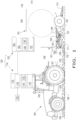
- feeder system 108 of baler 101 including pickup assembly 111, rotary feeder assembly 121, and windguard assembly 128.
- Pickup assembly 111 includes a plurality of pickup tines 240 which are configured to pick up the windrow of crop material 136 from the ground as tines 240 rotate in a counter-clockwise direction (as viewed from the bottom left of the page of FIG. 2 ), with crop 136 moving in a normal flow direction 132 once picked up by tines 240.
- Pickup assembly 111 further includes a frame 241 (which can be referred to as a pickup frame 241) including a windguard mounting device 242 on each lateral side of feeding system 108, which can be fastened to other portions of pickup frame 241, such as by way of rivets or threaded fasteners, such as bolts or screws, or the like.
- Windguard mounting device 242 further includes a stop mechanism 243 configured to selectively receive thereon a portion of windguard assembly 128; windguard mounting device 242 can be attached to pickup frame 241 in any suitable manner, such as by way of welding or by way of fasteners.
- Windguard frame 241 and windguard mounting device 242 can each be made of any suitable material, such as steel or a polymer.
- Rotary feeder assembly 121 includes rotors 144, each of which includes a plurality of generally triangular shaped tines, the rotors 144 being configured to move crop material 136 towards bale chamber 109 as rotors 144 rotate in a clockwise direction (as viewed from the bottom left of the page of FIG. 2 ).
- Windguard assembly 128 is coupled with pickup assembly 111 and, according to an exemplary embodiment of the present invention, includes a first arm 245 (on each lateral side of feeding system 108), a second arm 246 (on each lateral side of feeding system 108), a roller 247, a tine mechanism 248, a chain assembly 249, a linkage assembly 250 (on each lateral side of feeding system 108), and an actuator 251 (on each lateral side of feeding system 108 as shown in FIG. 2 , though optionally only one such actuator 251 may be included).
- Windguard assembly 128 can be substantially similar on both lateral sides of a midline running longitudinally, such that a description of one lateral side of windguard assembly 128 substantially serves as a description of the opposing lateral side of windguard assembly 128.
- Windguard assembly 128 is configured for selectively occupying a first position 237 and a second position 438, the first position 237 being associated with normal flow direction 132 of a crop material 136 relative to the feeder system 108, the second position 438 being associated with a reversal of the normal flow direction 132 of the crop material 136 (and thus a reversed flow direction 133).
- the first position 237 is when windguard assembly 128 occupies, at least in part, a rearward position (as in FIG. 2 )
- the second position 438 is when windguard assembly 128 occupies, at least in part, a forward position (as in FIG. 4 ).
- First arm 245 (which can be referred to as a fore member or forearm) is pivotably coupled at connection 265A with windguard mounting device 242 of pickup assembly 111 at a proximal end 352 of first arm 245 (stated another way, first arm 245 is supported by a pivot mount on windguard mounting device 242 of pickup assembly 111).
- first arm 245 is shown in an intermediate position when second arm 246 is retracted and resting on stop mechanism 243.
- Connection 265A can be made by any suitable connectors and/or fasteners, such as rivets, pins, screws, nuts, washers, bearings, and/or bolts.
- first arm 245 can define a first arm channel 253 as shown in FIG.
- First arm 245 can be made of any suitable material, such as steel, a polymer, or carbon fiber, and can be made in any suitable manner, such as stamping, metal forming, welding, and/or injection molding.
- Second arm 246 (which can be referred to as a rear member or rear member) is pivotably coupled with first arm 245 at connection 265B (at a distal end 355 of first arm 245 and a proximal end of second arm 246) and can define, at least in part, a second arm channel 256. Second arm 246 is also pivotably coupled with opposing ends of windguard roller 247 at connection 265C (at a distal end of second arm 246). Connections 265B and 265C can be made by any suitable connectors and/or fasteners, such as rivets, pins, screws, nuts, washers, bearings, and/or bolts.
- Second arm 246 can be made of any suitable material, such as steel, a polymer, or carbon fiber, and can be made in any suitable manner, such as stamping, metal forming, welding, and/or injection molding.
- Roller 247 extends between opposing second arms 246 across a front portion of windguard assembly 128 and can pivot in either direction, as is known, as crop material 136 contacts roller 247.
- the windguard assembly of the present invention is discussed as having a roller, it can be appreciated that the present invention is not limited to a type of windguard assembly having a roller (and thus includes windguard assemblies without a roller).
- Tine mechanism 248 includes a bar 259 (which can also be referred to as a tube 259, or tine bar 259) and a plurality of tines 260 rigidly connected to bar 259, tines 260 projecting generally in an aft direction.
- Bar 259 is pivotably coupled with second arm 246 at connection 265D, such that bar can extend through each second arm 246 (this is different than a known prior art device, wherein a tine bar is welded to an arm).
- Connection 265D can be made by any suitable connectors and/or fasteners, such as rivets, pins, screws, nuts, washers, bearings, and/or bolts.
- Tines 260 are configured for riding on a top portion of crop material 136 as crop material flows through feeder system 108 and thereby serves, at least in part, to retain crop material 136 within feeder system 108 and on a proper path to bale chamber 109.
- Tine mechanism 248 can be made of any suitable material, such as steel, a polymer, or carbon fiber, and can be made in any suitable manner, such as stamping, metal forming, welding, and/or injection molding.
- Chain assembly 249 can include one or more chains 261 (such as two, as shown in FIG. 2 ). Each chain 261 can extend between tine mechanism 248 and a front portion of baler 101 on baler frame 130 so as to be pivotal therewith (by way of a hook(s), for example) and thereby hold and thus support portions of windguard assembly 128 when not otherwise supported, for example, by actuator 251 and/or crop material 136. More specifically, first and second arms 245, 246 can receive support by way stop mechanism 243 (i.e., FIGS. 2 , 4 , 6 ), crop material 136 (i.e., flowing normally through feeder system 108, as a plug, or as a plug being backed out of feeder system 108), or chain 261.
- stop mechanism 243 i.e., FIGS. 2 , 4 , 6
- crop material 136 i.e., flowing normally through feeder system 108, as a plug, or as a plug being backed out of feeder system 108
- chain 261 can suspend at least portions of windguard assembly 128 when windguard assembly 128 is not otherwise supported by stop mechanism 243 or crop material 136; when chain 261 supports portions of windguard assembly 128 chain 261 can be taut, and when it does not chain 261 can be slack.
- Chain assembly 249 can also include a chain sleeve 262 surrounding at least a portion of each chain 261, chain sleeve 262, at least in part, keeping chain 261 substantially straight in the vicinity of the connection between chain 261 and tine mechanism 248 and can help chain 261 from interfering with other nearby structure.
- Chain sleeve 262 can be a relatively rigid material, such as a plastic pipe, and or made of flexible material.
- Linkage assembly 250 includes a first linkage 263 and a second linkage 264 pivotably coupled with first linkage 263.
- First linkage 263 (which can be referred to as a push rod 263) can be pivotably coupled with first arm 245 at connection 265E (at a proximal end of first linkage 263), which can be made by any suitable connectors and/or fasteners, such as rivets, pins, screws, nuts, washers, bearings, and/or bolts.
- First and second linkages 263, 264 can be pivotably coupled together at connection 265F (at a distal end of first linkage 263), which can be made by any suitable connectors and/or fasteners, such as rivets, pins, screws, nuts, washers, bearings, and/or bolts.
- Second linkage 264 (which can be referred to as a crank arm 264) can also be rigidly connected to bar 259, in any suitable way, such as by welding.
- First and second linkages 263, 264 can be made of any suitable material, such as steel, a polymer, or carbon fiber, and can be made in any suitable manner, such as stamping, metal forming, welding and/or injection molding.
- linkage assembly 250 is configured for moving tine mechanism 248 between a down position 267 and an up position 468 when second arm 246 moves between a retracted position 257 and an extended position 458, respectively, FIG. 2 showing tine mechanism 248 in the down position 267 and second arm 246 in the retracted position 257.
- the present invention provides linkage assembly 250 which is configured for rotating and thereby for changing an angle of tines 260 dependent on pivot connection 265B.
- Actuator 251 is pivotably coupled with first arm 245 and second arm 246 at connections 265G and 265H, respectively, each of which can be made by any suitable connectors and/or fasteners, such as rivets, pins, screws, nuts, washers, bearings, and/or bolts.
- Actuator 251 can be of any suitable configuration or type.
- actuator 251 can be a linear actuator or a rotary actuator.
- actuator can be a hydraulic cylinder assembly, a pneumatic cylinder assembly, or an electrically actuated cylinder assembly (which can include gearing and/or screws, for example).
- actuator 251 is shown and described as a linear actuator 251, more specifically, a hydraulic cylinder assembly 251, including a cylinder (which can also be referred to as a barrel), a piston within the cylinder, and a rod coupled with the piston.
- the cylinder can receive (in a portion of the cylinder) a hydraulic fluid (such as hydraulic oil), so as to cause the piston to be displaced within the cylinder and thereby to move the rod, causing the rod to extend; conversely, the hydraulic fluid can be caused to exit from a portion of the cylinder, so as to cause the piston to be displaced in an opposite direction within the cylinder and thereby to move the rod, causing the rod to retract.
- a hydraulic fluid such as hydraulic oil
- FIG. 2 shows the cylinder of actuator 251 including ports through which hydraulic fluid can enter and exit the cylinder, though additional structure of a hydraulic system (of which actuator 251 is a part) is not shown.
- a hydraulic system can include valving (for metering the proper amount of hydraulic fluid entering and exiting the cylinder), hydraulic lines, a reservoir of hydraulic fluid, and a pump, though other structures can be included or substituted therefor; structure of the hydraulic system can be maintained on baler 101 and/or work vehicle 100.
- Connection 265G is made with the cylinder of cylinder assembly 261, and connection 265H is made with the rod of cylinder assembly 251.
- Actuator 251, as shown in FIG. 2 can be positioned, at least in part, within first arm channel 253 and second arm channel 256.
- first arm channel 253 includes side walls each defining an arcuate slot 254, and the pin or shaft of the connector or fastener of connection 265H connects the rod of cylinder assembly 251 not only with second arm 246 (pivotably) but also with first arm 245 by way of the opposing slots 254, such that the rod of cylinder assembly 251 is slidably coupled with first arm 245 by way of slots 254.
- Actuator 251 is configured for moving second arm 246 between the retracted position 257 of second arm 246 and the extended position 458 of second arm 246, the retracted position 257 being associated with the first position 237 of windguard assembly 128, the extended position 458 being associated with the second position 438 of windguard assembly 128.
- FIG. 2 shows windguard assembly 128 in the first position 237, the rod of actuator 251 being extended to its farthest extent (such that the pin or shaft of connection 265H is seated at a distal end of slot 254), second arm 246 being in the retracted position 257, and tines 260 being in their down position 267.
- actuator 251 when actuator 251 is activated (i.e., by user, and/or by controller(s) 115, 123), second arm 246 is rotated relative to first arm 245 about an axis of rotation at connection 265B. More specifically, when windguard assembly is positioned as shown in FIG. 2 , retraction of the rod of actuator 251 causes second arm 246 to pivot counter-clockwise (viewed from the bottom left of the page of FIG.
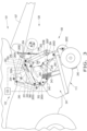
- Feeder system 108 is shown to include pickup assembly 111, pickup tines 240, pickup frame 241, windguard mounting device 242, and windguard assembly 128.
- Windguard assembly 128 is shown in two orientations, with first arm 245 at an intermediate position (in solid lines, and substantially similar to the orientation of windguard assembly 128 in FIG. 2 ), and with first arm 245 rotated up (counter-clockwise on the page of FIG. 3 )(in broken lines). Both orientations of windguard assembly 128 shown in FIG.
- FIG. 3 show windguard assembly 128 in normal operation and thus in the first position 237, considering that second arm 246 has not been extended forward by actuator 251 (second arm 246 is fully retracted, in retraction position 257) and thus also tine mechanism 248 remains in its down position 267; being in the first position 237, windguard assembly 128 (in either orientation in FIG. 5 ) is not yet positioned for a plug of crop material 136 to be cleared.
- second arm 246 is retracted and resting on stop mechanism 243.
- First arm 245 includes proximal end 352 and distal end 355.
- Actuator 251 includes a proximal end 366 which is pivotably coupled with proximal end 352 of first arm 245 (alternatively, actuator 251 could be reversed, with its proximal end 352 being pivotably coupled with second arm 246, rather than proximal end 352 of first arm 245).
- FIG. 3 thus depicts a normal operating position of windguard assembly 128, with windguard assembly 128 at resting height dictated by stop mechanism 243 (or, if not stop mechanism 243, then the length of chain 261).
- each of connections 265A-H is a pivotal connection, such that rotation with respect to each connection 265A-G occurs about a respective axis of rotation that is perpendicular to the page of FIG. 3 .
- This first orientation (in solid lines) of first arm 245 can occur when no or a relatively small quantity of crop material 136 is flowing through feeder system 108.
- first arm 245 at connection 265A is generally free-floating, in the sense that first arm 245 can pivot at connection 265A about a rotational axis extending between connections 265A depending upon the quantity of crop material 136.
- a larger quantity of crop material 136 pushes first arm 245 up so as to rotate a greater degree counter-clockwise at connection 265A, and, conversely, a lesser quantity of crop material 136 enables first arm 245 to rotate a greater degree clockwise at connection 265A (so long as this rotation clockwise is not blocked by stopping mechanism 243 of the length of chain 261).
- windguard assembly 128 can be said to swing or be suspended by chain 261. With regard to the orientation of windguard assembly 128 shown in FIG.
- first arm 245 can freely pivot at connection 265A, depending upon the amount of crop material 136 in feeder system 108 (whether crop material 136 is not plugged, or is plugged, in feeder system 108).
- control system 122 is shown according to one embodiment of the present invention, that is, to include position sensors 335A, 335B relative to windguard assembly 128 (alternatively, the present invention is not required to be used in conjunction with sensors, such as position sensors 335A, 335B, but the present invention can function by user controlling, for example, hydraulic remotes/valves manually with sensors being absent).
- control system 122 can further include not only controller 123 but also sensor 335A and/or sensor 335B (additional sensors can be employed, such as additional position sensors for sensing a position of windguard assembly 128), each of which can be position sensors (for illustrative purposes controller 123 and sensors 335A, 335B are shown only in FIG.
- Sensors 335A, 335B are operatively coupled with controller 123 (and also controller 115) and are each configured to help determine whether windguard assembly 128 is in the first position 237 or the second position 438.
- Sensor 335A can be positioned to sense a position of the rod of actuator 251, a position of second arm 246 relative to first arm 245, and/or a position of first linkage 263 relative to first arm 245 (alternatively, sensor 335A, or another position sensor, could be placed inside the cylinder of actuator 251 to sense a position of the piston within the cylinder).
- the position of the rod of actuator 251 corresponds with the position of second arm 246, indicating whether second arm 246 is fully retracted, fully extended (and thus forward), or at an intermediate position therebetween. Further, in sensing the position of the rod, this sensing can be done by sensing a position of the pin or shaft of connection 265H within slot 254. In sensing the position of second arm 246 relative to first arm 245, sensor 335A can sense a linear and/or angular position of second arm 246 relative to first arm 245. In sensing the position of first linkage 263 relative to first arm 245, sensor 335A can sense, for example, an angular position of first linkage 263 relative to first arm 245.
- Sensor 335B can be positioned to sense a position of second linkage 264 relative to first linkage 263, a position of second linkage 264 and/or bar 259 relative to second arm 246, and/or a position of tines 260 relative to second arm 246.
- sensor 335B In sensing the position of second linkage 264 relative to first linkage 263, sensor 335B can be positioned on or near first or second linkage 263, 264 and can be configured to sense an angular position of second linkage 264 relative to first linkage 263.
- sensor 335B can sense an angular position of second linkage 264 and/or bar 259 relative to second arm 246.
- sensor 335B can sense a linear or angular position of tines 260 relative to second arm 246. Upon sensing any of these respective positions, sensor(s) 335A, 335B can output a respective position signal to controller 123. Controller 123 is configured for receiving the respective position signals from sensors 335A, 335B. Upon receiving these respective position signals, controller 123 can output position information to controller 115 based at least in part on these position signals, which can output this information to user by way of input/output device 120.
- Windguard assembly 128 can adjust its position, in accordance with the user's command. Adjustment of the positioning of windguard assembly 128 can occur while baler 101 is or is not traversing across the ground, depending upon the circumstances, though removal of a plug of crop material 136 can be typically performed when baler 101 is not traversing the ground. User's command can thus move windguard assembly into first position 237 and second position 438, depending upon the circumstances.
- the present invention provides for in-cab adjustment of windguard assembly 128 to remove a plug of crop material 136.
- windguard assembly 128 can be (as discussed herein) with second arm 246 fully retracted, a user may find it advantageous to run windguard assembly 128 with second arm 246 at least partially extended during normal operation of baler 101 (when baler 101 traverses the ground so as to pick up a windrow of crop material 136), depending, for instance, on crop types and conditions; such a configuration of windguard assembly 128 can be controlled by user from cab 105 by way of input/output device 120.
- second arm 246 may be at least partially extended, not necessarily while baler 101 is traversing the ground, but when baler 101 is stopped for other reasons than for clearing a crop plug, such as for maintenance of feeder system 108 or any other aspect of baler 101. That is, extending second arm 246 and thus also moving tine mechanism 248 upwardly can create additional space within feeder system 108 and thereby improve accessibility to feeder system 108, such as for maintenance of pickup assembly 111, rotary feeder assembly 121, windguard assembly 128, and/or for replacement of tines 240 or hoops (i.e., which tines 240 pass between).
- control system 129 can be configured to automatically unplug feeder system 108 of a plug of crop material 136, without the user having to enter a command to do so (this alternative can occur with a user operating tractor 100 pulling baler 101, or with autonomous tractor and/or baler operations).
- control system 122 of baler 101 can include at least one sensor configured for: (a) sensing a plug of crop material 136 in feeder system 108 (for example, optical sensors detecting a profile of crop material 136 indicative of a plug of crop material, and/or weight sensors detecting a weight of crop material 136 indicative of a plug of crop material 136, and/or any other sensor(s) suitable for detecting a plug of crop material 136); and (b) outputting a plug signal corresponding to the plug sensed by the sensor.
- a sensor configured for: (a) sensing a plug of crop material 136 in feeder system 108 (for example, optical sensors detecting a profile of crop material 136 indicative of a plug of crop material, and/or weight sensors detecting a weight of crop material 136 indicative of a plug of crop material 136, and/or any other sensor(s) suitable for detecting a plug of crop material 136).
- Controller 123 (and/or controller 115) is configured for: (a) receiving this plug signal; (b) for outputting an adjustment signal, based at least in part on the plug signal, so as to adjust windguard assembly 128 so as to remove the plug of crop material 136 and thereby to move windguard assembly to second position 438; and (c) after removal of the plug, for outputting an additional adjustment signal, based at least in part upon another position signal indicative of windguard assembly 128 being in second position 438 and another signal indicative of the removal of the plug of crop material (i.e., another optical signal indicating a profile, or lack thereof, of crop material 136, or a weight or mass of crop material 136, indicating an absence of the plug), for moving windguard assembly 128 back to first position 237 for normal operation of baler 101.
- another optical signal indicating a profile, or lack thereof, of crop material 136, or a weight or mass of crop material 136, indicating an absence of the plug
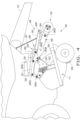
- Feeder system 108 is shown to include pickup assembly 111 with tines 240, and windguard assembly 128.
- windguard assembly 128 is in the second position 438 in FIG. 4 , considering that second arm 246 has been extended forward by actuator 251 (second arm 246 is fully extended to extended position 458) and thus also tine mechanism 248 is now in its up position 468.
- second position 538 windguard assembly 128 is positioned for a plug of crop material 136 to be cleared and thus is not in normal operating position for normal operation of baler 101 (that is, when crop material 136 is flowing into bale chamber 109).
- Hydraulic cylinder assembly 251 has retracted its rod, pulling back the pin or shaft of connection 265H to a proximal end of slot 254, which has caused: (a) second arm 246 to pivot counter-clockwise (viewed from a bottom left of the page of FIG. 4 ) at connection 265B so that roller 247 extends farther forward; and (b) first linkage 263 has pivoted at connection 265E and has pushed second linkage 264 forward at connection 265F, which has caused second linkage 264 to pivot bar 259 at connection 265D, resulting in tines 260 moving from their down position 267 (which is their downmost position) to their up position 468 (which is their upmost position).
- first arm 245 has pivoted clockwise (and thus farther downward) at connection 265A.
- the crop material 136 can be reversed (in direction 133, FIG. 1 ), which can occur, for example, when rotors 144 are reversed so as to remove a plug of crop material 136.
- second position 438 is associated with a reversed operation of rotors 144.
- first arm 245 can pivot at connection 265A, as shown to occur in FIG. 3 .
- FIG. 4 shows first arm 245 in a downmost position, with first and/or second arm 245, 246 resting on stop mechanism 243; when arm(s) 245, 246 do not rest on stop mechanism 243, chain 261 can be taut, suspending at least portions of windguard assembly 128 (in this way, the height of windguard assembly 128 can depend upon the amount of crop material 136 (whether as a plug or not) in feeder system 108, the height of stop mechanism 243, or the length of chain 261).
- This orientation of first arm 245 shown in FIG.
- first arm 245 can freely pivot at connection 265A, depending upon the amount of crop material 136 in feeder system 108.
- first arm 245 can pivot at connection 265A upward (counter-clockwise) due to an increased amount of crop material 136 in feeder system 108.
- tines 260 can generally ride on a top portion of a mat of crop material 136, or a plug of crop material 136 that has plugged or jammed in feeder system 108.
- windguard roller 247 may roll over the top of the plug during extension of second arm 246 by actuator 251, in which case support chains 261 can be slack.
- windguard assembly 128 can be run in first position 237 during normal operation of baler 101.
- user i.e., in cab 105 of tractor 100
- rotors 144 can be reversed (either by the same command or by way of an additional command) so that crop material 136 is reversed (in direction 133) and thereby backed out of feeder system 108.
- windguard assembly 128 can be returned to first position 237, so that baling of crop material 136 can continue.
- this removal of crop material, and return to normal operation of baler 101, can be performed automatically by control system 129.
- FIGS. 5-6 there is shown a second embodiment of the present invention. All prior reference numbers remain the same or are increased by a multiple of 100 and are substantially similar to the structures and function of the embodiment shown in FIGS. 2-4 , unless otherwise shown and/or described; thus, in an effort to avoid repetition, what is shown or described with respect to FIGS. 2-4 applies to FIGS. 5-6 , unless otherwise shown or described differently with respect to FIGS. 5-6 ( FIG. 1 is generic to both embodiments shown in FIGS. 2-6 ).
- the primary difference between the first embodiment and the second embodiment is the windguard assembly.
- baler 501 which can be pulled by tractor 100, includes baler control system 522, which includes controller 123 and sensor(s) 635A, 635B, and baler control system 522 is a part of unified control system 529, which also includes tractor control system 114. Further, baler 501 includes feeder system 508.
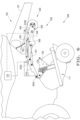
- Feeder system 508 includes pickup assembly 111, rotary feeder assembly 121, and windguard assembly 528, which is shown in first position 537.
- Pickup assembly 111 includes pickup tines 240, pickup frame 241, windguard mounting device 242, and stop mechanism 243, substantially as described above.
- Rotary feeder assembly 121 includes rotors 144, substantially as described above.
- Windguard assembly 528 includes first arm 545, second arm 546, roller 547, tine mechanism 548, chain assembly 549, linkage assembly 550, actuator 551, and connections 565A-H (each of which is a pivot connection).
- First arm 545 is pivotably coupled with windguard mounting device 242 at connection 565A and includes proximal end 552, distal end 555, central section 569, and first arm channel 553.
- Second arm 546 is pivotably coupled with first arm 545 at connection 565B, includes second arm channel 556, and is shown in FIG. 5 in retracted position 557, resting on stop mechanism 243 (if second arm 546 were not resting on stop mechanism 243, then second arm 546 can be supported and thus suspended by chain 561, or supported by crop material 136).
- Roller 547 is pivotably connected with second arm 546 at connection 565C.
- Tine mechanism 548 includes tine bar 559 and tines 560, and bar 559 is pivotably coupled with second arm 546 at connection 565D. With second arm 546 in retraction position 557 in FIG. 5 , tine mechanism 548 is in down position 567.
- Chain assembly 549 includes a chain 561 and can include a chain sleeve (not shown in FIG. 5 ).
- Linkage assembly 550 includes first linkage 563 (pivotably connected to first arm 545 at connection 565E) and second linkage 564 pivotably coupled with first linkage at connection 565F. Second linkage 564 is rigidly connected with tine bar 559, such as by welding.
- Actuator 551 can be a hydraulic cylinder assembly with the cylinder, the piston, and the rod, though other types of actuators can be used (as described above).
- Actuator 551 includes a proximal end 566, which can include a proximal end of the cylinder (as shown in FIG. 5 ).
- Proximal end 566 is pivotably connected to first arm 545 at connection 565G; more specifically, proximal end 566 is pivotably coupled with central section 569 of first arm 545 at connection 565G.
- a distal end of actuator 551 can be formed by the rod and is pivotably coupled with second arm 546 at connection 565H.
- connection 565H does not involve sliding a pin or shaft of connection 565H within a slot formed by first arm 545.
- second arm 546 extends forward, causing second arm 546 to rotate counter-clockwise (viewed from the bottom left in the page of FIG. 5 ) about connection 565B; conversely, when the rod of actuator 551 retracts, second arm 546 retracts backward, causing second arm 546 to rotate clockwise about connection 565B.
- windguard assembly 528 can pivot about connection 565A depending upon the quantity of crop material 136.
- baler 501 with feeder system 508, with windguard assembly 528 being in second position 638.
- second arm 546 is in extended position 658, and tine mechanism 548 is in up position 668.
- windguard assembly 528 is configured for clearing of a crop plug.
- second arm 546 can be suspended by a taut chain 561 (or, alternatively, be supported by crop material 136, either as a plug or not).
- first arm 545 has rotated clockwise about connection 565A (relative to FIG. 5 ).
- first arm 545 can rotate at pivot connection 565A depending upon the quantity of crop material 136.
- FIG. 6 shows windguard assembly 528 with first arm 545 pivoted up. This can occur when windguard assembly encounters a relatively large volume of crop material 136, which can cause first arm 545 to pivot about an axis of rotation (perpendicular to the page of FIG. 6 ) associated with connection 565A.
- first arm 545 can be pivoted downwards (clockwise) when encountering less crop material, and can be stopped by stop mechanism 243 and/or chain 561.
- feeder system 508 can be used substantially similarly to what is described with respect to feeder system 108.
- sensors 635A, 635B are substantially similar to sensors 335A, 335B and thus are also position sensors that send their data to controller 123 (and/or controller 115), except that sensor 635A does not sense positional information relative to a slot similar to slot 254.
- position sensors 635A, 635B are optional, such that the present invention can be used without them. That is, as with the first embodiment, a user can still enter a command (such as by way of device 120) to clear a crop plug, even without information from sensors 635A, 635B.
- the windguard assembly of the present invention can be mounted to baler tongue 107.
- any of the embodiments of the windguard assembly according to the present invention can be adapted so as to mount to tongue 107.
- the windguard assembly may omit the roller, or may have a baffle in place of tines.
- FIG. 7 there is shown a flow diagram showing a method 790 of using an agricultural baler 101, 501, the method 790 including the steps of: providing 791 a baler frame 130 and a feeder system 108, 508, the feeder system 108, 508, being coupled with the baler frame 130 and including a windguard assembly 128, 528; occupying 792 selectively, by the windguard assembly 128, 528, a first position 237, 537, the first position 237, 537 being associated with a normal flow direction 132 of a crop material 136 relative to the feeder system 108, 508; and occupying 793 selectively, by the windguard assembly 128, 528 a second position 438, 638, the second position 438, 638 being associated with a reversal 133 of the normal flow direction 132 of the crop material 136.
- the feeder system 108, 528 can include a pickup assembly 111 and a rotary feeder assembly 121 each of which is coupled with the baler frame 130, the windguard assembly 128, 528 being coupled with the pickup assembly 111, the rotary feeder assembly 121 including a rotor device 144, the second position 438, 638 being associated with a reversed operation of the rotor device 144.
- the windguard assembly 128, 528 can include: a first arm 245, 545 pivotably coupled with the pickup assembly 111; a second arm 246, 546 pivotably coupled with the first arm 245, 545; an actuator 251, 551 pivotably coupled with the first arm 245, 545 and the second arm 246, 546 and configured for moving the second arm 246, 546 between a retracted position 257, 557 and an extended position 458, 658, the retracted position 257, 557 being associated with the first position 237, 537, the extended position 458, 658 being associated with the second position 438, 638; a tine mechanism 248, 548 pivotably coupled with the second arm 246, 546; a linkage assembly 250, 550 coupled with the first arm 245, 545 and the tine mechanism 248, 548 and configured for moving the tine mechanism 248, 548 between a down position 267, 567 and an up position 468, 668 when the second arm 245, 545 moves between the retracted position 257, 557 and the extended position 458, 658, respectively.
- the first arm 245 can include a proximal end 352, the actuator 251 including a proximal end 366 which is pivotably coupled with the proximal end 352 of the first arm 245.
- the first arm 545 can include a central section 569, the actuator 551 including a proximal end 552 which is pivotably coupled with the central section 569 of the first arm 545.
- controller 115, 123 upon loading and executing software code or instructions which are tangibly stored on a tangible computer readable medium, such as on a magnetic medium, e.g., a computer hard drive, an optical medium, e.g., an optical disc, solid-state memory, e.g., flash memory, or other storage media known in the art.
- a tangible computer readable medium such as on a magnetic medium, e.g., a computer hard drive, an optical medium, e.g., an optical disc, solid-state memory, e.g., flash memory, or other storage media known in the art.
- any of the functionality performed by controller 115, 123 described herein, such as the method 790 is implemented in software code or instructions which are tangibly stored on a tangible computer readable medium.
- the controller 115, 123 loads the software code or instructions via a direct interface with the computer readable medium or via a wired and/or wireless network.
- controller 115, 123 may perform any of the functionality of controller
Abstract
Description
- The present invention pertains to an agricultural baler, and, more specifically, to a windguard assembly of the agricultural baler.
- Agricultural harvesting machines, such as agricultural balers (which can be referred to as balers), have been used to consolidate and package crop material (which can also be referred to as forage, forage material, or forage crop material) so as to facilitate the storage and handling of the crop material for later use. Often, a mower-conditioner cuts and conditions the crop material and forms it into a swath or windrow to dry in the sun. When the cut crop material is properly dried (depending upon the application), an agricultural harvesting machine, such as an agricultural baler, travels along the swath or windrows (hereinafter, collectively referred to as windrows, unless otherwise specified) to pick up the crop material. Agricultural balers can be, for example, round balers, large square balers, and small square balers, which form the bales into corresponding shapes, as is known.
- More specifically, with respect to round balers, pickups of the baler gather the cut and windrowed crop material from the ground, and then convey the cut crop material toward a bale-forming chamber within the baler (that is, the bale chamber). A drive mechanism operates to activate any pickups of a pickup assembly, augers, and/or a rotor (which can be referred to as a feeder) of a rotary feeder assembly of a feeder system. A pickup can convey crop material in an overshot manner, while a rotor can convey crop material toward or into the bale chamber in an undershot manner. A conventional bale chamber of a round baler may include a pair of opposing sidewalls with a series of rolls (which can be referred to as rollers) and belts that rotate and compress the crop material into a cylindrical shape. When the bale has reached a desired size and density, a wrapping assembly, which includes wrap material, may wrap the bale to ensure, at least in part, that the bale maintains its shape and density. The wrap material can include a film (such as a flexible plastic wrap) or a net (which can be referred to as net wrap). For example, wrap material may be used to wrap the bale of crop material. After wrapping, a cutting or severing mechanism of the wrapping assembly may be used to cut the wrap material once the bale has been wrapped. The wrapped bale may be ejected from the baler and onto the ground by, for example, raising a tailgate of the baler. The tailgate is then closed, and the cycle repeated as necessary and desired to manage the field of cut crop material.
- The feeder system can include not only the pickup assembly and the rotor assembly, for example, but also a floor, a cutting assembly, and a windguard assembly. The pickup includes a plurality of tines to pick up the crop material disposed in a windrow. The rotor, which is downstream of the pickup, can be positioned above the floor which the crop material traverses prior to entering the bale chamber and can work in conjunction with, and cooperatively with, the cutting assembly. The rotor can include a rotor shaft (extending transversely) and a plurality of tines (which can have a generally triangular or star-shaped configuration) spaced apart across the transverse extent of the baler. The tines are configured to engage and thereby to push the crop material towards the bale chamber and can be grouped in pairs, with a relatively short distance between the tines of a given pair. The floor can include a plurality of slots across the transverse extent of the floor, each slot extending longitudinally in the floor (that is, parallel or otherwise aligned with a direction of crop flow). The cutting assembly can include a plurality of knives (which can also be referred to as cutters) which are selectively received in the slots of this floor, respectively. When inserted through the slots so that the knives extend at least partially above the floor, each respective knife (depending upon the design) can extend between a pair of tines of the rotor, as the rotor shaft rotates the tines. Further, the knives, as they extend through the slots above the floor are configured to cut the crop material to a predetermined length, as the crop material passes by the knives prior to the crop material entering the bale chamber. These knives can be configured to drop at least partially below the floor upon being struck by a foreign object. The windguard assembly can include a roller and a plurality of tines extending aft and can be configured to retain the crop material along at least a part of its flow path as it proceeds rearward by the pickup and the rotor to the bale chamber and, in so doing, can be positioned adjacent to an upper portion of the crop material. Further, the windguard assembly can be pivotably attached to the pickup assembly.
- Occasionally, such as with round balers, the crop material becomes plugged in the feeder system. That is, the crop material bunches up so as to form a plug of crop material (which can be referred to as a crop plug), which does not allow, or otherwise at least partially inhibits, the crop material from flowing from the feeder system into the bale chamber. Round balers prone to plugging can have a variable position (drop) floor below the rotor (also known as the feeder) that allows the crop plug to be passed, by increasing a space between the floor and the rotor. Such a drop floor can be effective in unplugging if only the rotor is plugged but often is not effective for unplugging when the crop material is plugged between the windguard assembly and the pickup (resulting in a pickup plug). Such a plug can result, for example, when an operator's ground speed has exceeded the feeding capacity of the baler. When a plug of crop material occurs that cannot be cleared by the drop floor, some operators may use a manually or remotely operated rotor reverser of a reversing system (so as to reverse a direction of the flow of the crop material), which can be useful in loosening the crop material but typically is unable to clear a pickup entirely. The reversing system cannot effectively clear a pickup plug because a conventional construction of windguard assembly geometry acts as a barrier, preventing the flow of the crop material in the reverse direction. For, the tines of the windguard assembly act as barbs, jamming the crop material and thus stopping the reverse flow of crop material and preventing the crop from clearing. Manual removal of the plug, thus, is often necessary for a pickup plug, which often requires the operator to remove the windguard assembly and to pull the crop material out of the pickup assembly by hand - a timely, labor-intensive job which often occurs in uncomfortable field conditions (heat, bugs, dust).
- What is needed in the art is a way to reposition the windguard to facilitate removal of a plug of crop material from a feeder system when a drop floor is insufficient to do so, without having to clear the plug manually.
- The present invention provides an agricultural baler with a feeder system including a windguard assembly configured for selectively moving between a plurality of positions, such that a plug of crop material can be removed from the feeder system when the flow direction of the crop material in the feeder system is reversed.
- The invention in one form is directed to a windguard assembly of a feeder system of an agricultural baler, the agricultural baler including a baler frame, the feeder system being coupled with the baler frame, the windguard assembly including: the windguard assembly, which is configured for selectively occupying a first position and a second position, the first position being associated with a normal flow direction of a crop material relative to the feeder system, the second position being associated with a reversal of the normal flow direction of the crop material.
- The invention in another form is directed to an agricultural machine, including: a machine frame; and a feeder system coupled with the machine frame and including a windguard assembly, the windguard assembly being configured for selectively occupying a first position and a second position, the first position being associated with a normal flow direction of a crop material relative to the feeder system, the second position being associated with a reversal of the normal flow direction of the crop material.
- The invention in yet another form is directed to a method of using an agricultural baler, the method including the steps of: providing a baler frame and a feeder system, the feeder system being coupled with the baler frame and including a windguard assembly; occupying selectively, by the windguard assembly, a first position, the first position being associated with a normal flow direction of a crop material relative to the feeder system; and occupying selectively, by the windguard assembly, a second position, the second position being associated with a reversal of the normal flow direction of the crop material.
- An advantage of the present invention is that it provides a windguard design of variable geometry for use with a harvester pickup to allow effective rejection of a crop plug from the machine.
- Another advantage is that it provides that, in varying the geometry of the windguard, the windguard, or at least a portion thereof, can be extended forward to open up space for the crop plug to be removed.
- Yet another advantage is that it provides that, in varying the geometry of the windguard, the tines of the windguard can be pivoted so that they do not act as barbs when the plug is attempted to be removed.
- Yet another advantage is that the windguard assembly does not need to be removed in order to remove a crop plug.
- Yet another advantage is that a variation of the geometry of the windguard assembly can be controlled by a controller, based upon sensor feedback, in order to optimize crop feeding. Alternatively, the variation of the geometry of the windguard assembly can be controlled by a user.
- For the purpose of illustration, there are shown in the drawings certain embodiments of the present invention. It should be understood, however, that the invention is not limited to the precise arrangements, dimensions, and instruments shown. Like numerals indicate like elements throughout the drawings. In the drawings:
-
FIG. 1 illustrates a schematic side view of an exemplary embodiment of an agricultural vehicle, formed as a tractor, and an agricultural baler, the agricultural baler including a feeder system including a windguard assembly, in accordance with an exemplary embodiment of the present invention; -
FIG. 2 illustrates a perspective view of the feeder system of the agricultural baler ofFIG. 1 (at least partially schematically), the feeder system including the windguard assembly in a first position, with portions broken away, in accordance with an exemplary embodiment of the present invention; -
FIG. 3 illustrates a side view of the feeder system ofFIG. 2 (at least partially schematically), the windguard assembly being in the first position, with portions broken away; -
FIG. 4 illustrates a side view of the feeder system ofFIG. 2 (at least partially schematically), the windguard assembly being in the second position, with portions broken away; -
FIG. 5 illustrates a perspective view of another exemplary embodiment of the feeder system of the agricultural baler (at least partially schematically), the feeder system including the windguard assembly in the first position, with portions broken away, in accordance with an exemplary embodiment of the present invention; -
FIG. 6 illustrates a side view of the feeder system ofFIG. 5 (at least partially schematically), the windguard assembly being in the second position, with portions broken away; and -
FIG. 7 illustrates a flow diagram showing a method of using an agricultural baler, in accordance with an exemplary embodiment of the present invention. - The terms "forward", "rearward", "left" and "right", when used in connection with the agricultural vehicle, agricultural baler, and/or components thereof are usually determined with reference to the direction of forward operative travel of the agricultural vehicle and/or agricultural baler, but they should not be construed as limiting. The terms "longitudinal" and "transverse" are determined with reference to the fore-and-aft direction of the agricultural vehicle and/or agricultural baler and are equally not to be construed as limiting. The terms "downstream" and "upstream" are determined with reference to the intended direction of crop material flow during operation, with "downstream" being analogous to "rearward" and "upstream" being analogous to "forward."
- Referring now to the drawings, and more particularly to
FIG. 1 , there is shown an embodiment of an agricultural vehicle 100 (which can be referred to as a work vehicle 100) towing an agricultural baler 101 (any baler herein can be referred to as an agricultural machine), in accordance with the present invention, to perform a baling operation within a field (FIG. 1 is generic to all embodiments of the present invention discussed herein). As shown,work vehicle 100 can be configured as an agricultural tractor, such as an operator-driven tractor or an autonomous tractor. However, in some embodiments, thework vehicle 100 may correspond to any other suitable vehicle configured to tow a baler across a field or that is otherwise configured to facilitate the performance of a baling operation, including an autonomous baling vehicle. Additionally, as shown,baler 101 can configured as a round baler configured to generate round bales. However, in some embodiments,baler 101 may have any other suitable configuration, including being configured to generate square or rectangular bales. It should be further appreciated thatbaler 101, while shown as being towed bytractor 100, may also be a self-propelled baler that does not rely on a separate vehicle for propulsion and/or power to function. While the present invention is described with respect to a baler, it can be appreciated that other the present invention can be used in conjunction with other agricultural machines, such as vehicles and/or implements, such as a self-loading forage wagon. -
Work vehicle 100 includes a pair offront wheels 102, a pair ofrear wheels 103, and achassis 104 coupled to and supported by thewheels cab 105 may be supported by a portion of thechassis 104 and may house various input devices for permitting an operator to control the operation ofwork vehicle 100 and/orbaler 101. Additionally,work vehicle 100 may include an engine and a transmission mounted onchassis 104. The transmission may be operably coupled to the engine and may provide variably adjusted gear ratios for transferring engine power towheels 103 via a drive axle assembly. - As shown in
FIG. 1 ,work vehicle 100 may be coupled tobaler 101 via a power take-off (PTO) 106 and atongue 107 to a hitch ofwork vehicle 100 to allowvehicle 100 to towbaler 101 across the field. As such,work vehicle 100 may, for example, guidebaler 101 towardcrop material 136 deposited in windrows on the field. As is generally understood, to collect thecrop material 136,baler 101 includes a feeder system 108 (which can be referred to generally as a crop collector) mounted on a front end ofbaler 101.Feeder system 108 may, for example, include apickup assembly 111, arotary feeder assembly 121, afloor 131, and awindguard assembly 128.Pickup assembly 111 includes a rotating wheel with tines that collectcrop material 136 from the ground anddirect crop material 136 toward abale chamber 109 ofbaler 101 in an overshot manner (rotating clockwise inFIG. 1 ).Rotary feeder assembly 121 includes a rotating shaft (rotor shaft) and a plurality of rotor devices 144 (which can be referred to as rotors 144) mounted to the shaft so as to rotate about the shaft in a counter-clockwise manner (as seen inFIG. 1 and shown by arrow 134),rotors 144 configured to push or otherwise to movecrop material 136 towards or intobale chamber 109, in an undershot manner.Feeder system 108 can also include a rotating shaft (not shown inFIG. 1 ) generally betweenpickup assembly 111 androtary feeder assembly 121 that includes side augers for movingcrop material 136 inwardly prior to enteringbale chamber 109.FIG. 1 showscrop material 136 lying in a windrow on the ground of the field and being picked up bypickup assembly 111 offeeder system 108. Upon being picked up,crop material flow 136 flows overpickup assembly 111, underwindguard assembly 128, and underrotary feeder assembly 121, as indicated byarrow 132.Arrow 132 thus indicates thenormal flow direction 132 ofcrop material 136 relative tofeeder system 108. Conversely,arrow 133 shows a flow direction which is opposite the normal flow direction ofcrop material 136; thisopposite flow direction 133 can also be referred to as a reverse flow direction 133 (that is, a reversal of normal flow direction 132).FIG. 1 showsbaler 101 schematically and thus with one pair of wheels, though it can be appreciated thatbaler 101 can include one or more additional pair of wheels, as inFIG. 2 . - Inside
bale chamber 109, rollers, belts, and/or other devices compact thecrop material 136 to form a generally cylindrically-shapedbale 110.Bale 110 is contained withinbaler 101 until ejection ofbale 110 is instructed (e.g., by the operator and/or abaler controller 123 of baler 101). In some embodiments,bale 110 may be automatically ejected frombaler 101 oncebale 110 is formed, bybaler controller 123 detecting thatbale 110 is fully formed and outputting an appropriate ejection signal. Further,work vehicle 100 includes acontrol system 114, which includes acontroller 115, which includes aprocessor 116,memory 117,data 118, andinstructions 119.Control system 114 can further include an input/output device 120 such as a laptop computer (with keyboard and display) or a touchpad (including keypad functionality and a display),device 120 being configured for a user to interface therewith. - As shown in
FIG. 1 ,baler 101 may also include atailgate 112 movable between a closed position (as shown in the illustrated embodiment) and an opened position via a suitable actuator assembly.Tailgate 112 and/or the actuator assembly may be controlled to open and close bybaler controller 123. In the closed position,tailgate 112 may confine or retainbale 110 withinbaler 101. In the open position,tailgate 112 may rotate out of the way to allowbale 110 to be ejected from thebale chamber 109. Additionally, as shown inFIG. 1 ,baler 101 may include aramp 113 extending from its aft end that is configured to receive anddirect bale 110 away frombaler 113 as it is being ejected frombale chamber 109. In some embodiments,ramp 113 may be spring loaded, such thatramp 113 is urged into a raised position, as illustrated. In such embodiments, the weight ofbale 110 onramp 113 may driveramp 113 to a lowered position in whichramp 113 directsbale 110 to the soil surface. Oncebale 110 is ejected,bale 110 may roll downramp 113 and be deposited onto the field. As such,ramp 113 may enablebale 110 to maintain its shape and desired density by gently guidingbale 110 onto the field. Further,baler 101 includes acontrol system 122, which includescontroller 123, which includes aprocessor 124,memory 125,data 126, andinstructions 127.Controller 123 can communicate withcontroller 115, so thatcontroller 115 outputs information to the display of input/output device 120 ofwork vehicle 100, thereby informing a user of various conditions ofbaler 101 andbales 110 forming or formed therein. Further,baler 101 includes a frame 130 (which can be referred to asbaler frame 130, or more generally as a machine frame 130) to which all of the components ofbaler 101 are directly or indirectly coupled. Thus,feeder system 108 and thus alsopickup assembly 111,rotary feeder assembly 121, andwindguard assembly 128 are coupled withframe 130. - It should be appreciated that the configuration of
work vehicle 100 described above and shown inFIG. 1 is provided only as one example. Thus, it should be appreciated that the present disclosure may be readily adaptable to any manner of work vehicle configuration. For example, in an alternative embodiment, a separate frame or chassis may be provided to which the engine, transmission, and drive axle assembly are coupled, a configuration common in smaller tractors. Still other configurations may use an articulated chassis to steer work vehicle, or rely on tracks in lieu ofwheels work vehicle 100 may, in some embodiments, be configured as an autonomous vehicle. In such embodiments,work vehicle 100 may include suitable components for providing autonomous vehicle operation and, depending on the vehicle configuration, need not include the operator'scab 105. - Additionally, it should be appreciated that the configuration of
baler 101 described above and shown inFIG. 1 is provided only as one example. Thus, it should be appreciated that the present disclosure may be readily adaptable to any manner of baler configuration, or other agricultural machines, such as a vehicle and/or implement, such as a self-loading forage wagon. For example, as indicated previously,baler 101 may, in some embodiments, correspond to a square baler configured to generate square or rectangular bales. It should be further appreciated that the illustration ofbaler 101 inFIG. 1 is schematic. - Further, in general,
controllers controller memory controller respective processor memory data instructions respective controller respective memory Such memory data instructions data -
Baler controller 123, herein, is assumed to be the primary controller for controlling operations ofbaler 101. However,controller 123 ofbaler 101, as indicated inFIG. 1 , can be in communication withcontroller 115 ofwork vehicle 100, thereby forming aunified control system 129, such that any or all information associated with eithercontroller other controller controller other controller Controllers controllers controllers controllers 115, 123) which can be configured to perform any of the functions associated withcontrollers Controllers
communication therebetween, such as a local area network, a metropolitan area network, a wide area network, a neural network, whether wired or wireless. - Referring now to
FIG. 2 , there is shownfeeder system 108 ofbaler 101, feeder system 108 (shown in part schematically) includingpickup assembly 111,rotary feeder assembly 121, andwindguard assembly 128.Pickup assembly 111 includes a plurality ofpickup tines 240 which are configured to pick up the windrow ofcrop material 136 from the ground astines 240 rotate in a counter-clockwise direction (as viewed from the bottom left of the page ofFIG. 2 ), withcrop 136 moving in anormal flow direction 132 once picked up bytines 240.Pickup assembly 111 further includes a frame 241 (which can be referred to as a pickup frame 241) including awindguard mounting device 242 on each lateral side offeeding system 108, which can be fastened to other portions ofpickup frame 241, such as by way of rivets or threaded fasteners, such as bolts or screws, or the like.Windguard mounting device 242 further includes astop mechanism 243 configured to selectively receive thereon a portion ofwindguard assembly 128; windguard mountingdevice 242 can be attached topickup frame 241 in any suitable manner, such as by way of welding or by way of fasteners.Windguard frame 241 and windguard mountingdevice 242 can each be made of any suitable material, such as steel or a polymer.Rotary feeder assembly 121 includesrotors 144, each of which includes a plurality of generally triangular shaped tines, therotors 144 being configured to movecrop material 136 towardsbale chamber 109 asrotors 144 rotate in a clockwise direction (as viewed from the bottom left of the page ofFIG. 2 ). -
Windguard assembly 128 is coupled withpickup assembly 111 and, according to an exemplary embodiment of the present invention, includes a first arm 245 (on each lateral side of feeding system 108), a second arm 246 (on each lateral side of feeding system 108), aroller 247, atine mechanism 248, achain assembly 249, a linkage assembly 250 (on each lateral side of feeding system 108), and an actuator 251 (on each lateral side offeeding system 108 as shown inFIG. 2 , though optionally only onesuch actuator 251 may be included).Windguard assembly 128 can be substantially similar on both lateral sides of a midline running longitudinally, such that a description of one lateral side ofwindguard assembly 128 substantially serves as a description of the opposing lateral side ofwindguard assembly 128.Windguard assembly 128 is configured for selectively occupying afirst position 237 and asecond position 438, thefirst position 237 being associated withnormal flow direction 132 of acrop material 136 relative to thefeeder system 108, thesecond position 438 being associated with a reversal of thenormal flow direction 132 of the crop material 136 (and thus a reversed flow direction 133). In general, thefirst position 237 is whenwindguard assembly 128 occupies, at least in part, a rearward position (as inFIG. 2 ), and thesecond position 438 is whenwindguard assembly 128 occupies, at least in part, a forward position (as inFIG. 4 ). - First arm 245 (which can be referred to as a fore member or forearm) is pivotably coupled at
connection 265A with windguard mountingdevice 242 ofpickup assembly 111 at aproximal end 352 of first arm 245 (stated another way,first arm 245 is supported by a pivot mount on windguard mountingdevice 242 of pickup assembly 111). InFIG. 2 ,first arm 245 is shown in an intermediate position whensecond arm 246 is retracted and resting onstop mechanism 243.Connection 265A can be made by any suitable connectors and/or fasteners, such as rivets, pins, screws, nuts, washers, bearings, and/or bolts. Further,first arm 245 can define afirst arm channel 253 as shown inFIG. 2 , which can be substantially U-shaped. Side walls offirst arm channel 253 can each define aslot 254, which can be arcuate, for slidably receiving therein sliding structure, such as a pin or shaft of a connector or fastener, which can be part ofconnection 265H (below).First arm 245 can be made of any suitable material, such as steel, a polymer, or carbon fiber, and can be made in any suitable manner, such as stamping, metal forming, welding, and/or injection molding. - Second arm 246 (which can be referred to as a rear member or rear member) is pivotably coupled with
first arm 245 atconnection 265B (at adistal end 355 offirst arm 245 and a proximal end of second arm 246) and can define, at least in part, asecond arm channel 256.Second arm 246 is also pivotably coupled with opposing ends ofwindguard roller 247 atconnection 265C (at a distal end of second arm 246).Connections Second arm 246 can be made of any suitable material, such as steel, a polymer, or carbon fiber, and can be made in any suitable manner, such as stamping, metal forming, welding, and/or injection molding.Roller 247 extends between opposingsecond arms 246 across a front portion ofwindguard assembly 128 and can pivot in either direction, as is known, ascrop material 136contacts roller 247. Though the windguard assembly of the present invention is discussed as having a roller, it can be appreciated that the present invention is not limited to a type of windguard assembly having a roller (and thus includes windguard assemblies without a roller). -
Tine mechanism 248 includes a bar 259 (which can also be referred to as atube 259, or tine bar 259) and a plurality oftines 260 rigidly connected to bar 259,tines 260 projecting generally in an aft direction.Bar 259 is pivotably coupled withsecond arm 246 atconnection 265D, such that bar can extend through each second arm 246 (this is different than a known prior art device, wherein a tine bar is welded to an arm).Connection 265D can be made by any suitable connectors and/or fasteners, such as rivets, pins, screws, nuts, washers, bearings, and/or bolts.Tines 260 are configured for riding on a top portion ofcrop material 136 as crop material flows throughfeeder system 108 and thereby serves, at least in part, to retaincrop material 136 withinfeeder system 108 and on a proper path tobale chamber 109.Tine mechanism 248 can be made of any suitable material, such as steel, a polymer, or carbon fiber, and can be made in any suitable manner, such as stamping, metal forming, welding, and/or injection molding. -
Chain assembly 249 can include one or more chains 261 (such as two, as shown inFIG. 2 ). Eachchain 261 can extend betweentine mechanism 248 and a front portion ofbaler 101 onbaler frame 130 so as to be pivotal therewith (by way of a hook(s), for example) and thereby hold and thus support portions ofwindguard assembly 128 when not otherwise supported, for example, byactuator 251 and/orcrop material 136. More specifically, first andsecond arms FIGS. 2 ,4 ,6 ), crop material 136 (i.e., flowing normally throughfeeder system 108, as a plug, or as a plug being backed out of feeder system 108), orchain 261. With respect tochain 261,chain 261 can suspend at least portions ofwindguard assembly 128 whenwindguard assembly 128 is not otherwise supported bystop mechanism 243 orcrop material 136; whenchain 261 supports portions ofwindguard assembly 128chain 261 can be taut, and when it does notchain 261 can be slack.Chain assembly 249 can also include achain sleeve 262 surrounding at least a portion of eachchain 261,chain sleeve 262, at least in part, keepingchain 261 substantially straight in the vicinity of the connection betweenchain 261 andtine mechanism 248 and can helpchain 261 from interfering with other nearby structure.Chain sleeve 262 can be a relatively rigid material, such as a plastic pipe, and or made of flexible material. -
Linkage assembly 250 includes afirst linkage 263 and asecond linkage 264 pivotably coupled withfirst linkage 263. First linkage 263 (which can be referred to as a push rod 263) can be pivotably coupled withfirst arm 245 atconnection 265E (at a proximal end of first linkage 263), which can be made by any suitable connectors and/or fasteners, such as rivets, pins, screws, nuts, washers, bearings, and/or bolts. First andsecond linkages connection 265F (at a distal end of first linkage 263), which can be made by any suitable connectors and/or fasteners, such as rivets, pins, screws, nuts, washers, bearings, and/or bolts. Second linkage 264 (which can be referred to as a crank arm 264) can also be rigidly connected to bar 259, in any suitable way, such as by welding. First andsecond linkages linkage assembly 250 is configured for movingtine mechanism 248 between adown position 267 and an upposition 468 whensecond arm 246 moves between a retractedposition 257 and anextended position 458, respectively,FIG. 2 showing tine mechanism 248 in thedown position 267 andsecond arm 246 in the retractedposition 257. Thus, the present invention provideslinkage assembly 250 which is configured for rotating and thereby for changing an angle oftines 260 dependent onpivot connection 265B. -
Actuator 251, as shown inFIG. 2 , is pivotably coupled withfirst arm 245 andsecond arm 246 atconnections Actuator 251 can be of any suitable configuration or type. For instance,actuator 251 can be a linear actuator or a rotary actuator. As a linear actuator, actuator can be a hydraulic cylinder assembly, a pneumatic cylinder assembly, or an electrically actuated cylinder assembly (which can include gearing and/or screws, for example). Herein, by way of example and not limitation,actuator 251 is shown and described as alinear actuator 251, more specifically, ahydraulic cylinder assembly 251, including a cylinder (which can also be referred to as a barrel), a piston within the cylinder, and a rod coupled with the piston. As one example, the cylinder can receive (in a portion of the cylinder) a hydraulic fluid (such as hydraulic oil), so as to cause the piston to be displaced within the cylinder and thereby to move the rod, causing the rod to extend; conversely, the hydraulic fluid can be caused to exit from a portion of the cylinder, so as to cause the piston to be displaced in an opposite direction within the cylinder and thereby to move the rod, causing the rod to retract.FIG. 2 shows the cylinder ofactuator 251 including ports through which hydraulic fluid can enter and exit the cylinder, though additional structure of a hydraulic system (of which actuator 251 is a part) is not shown. Such a hydraulic system can include valving (for metering the proper amount of hydraulic fluid entering and exiting the cylinder), hydraulic lines, a reservoir of hydraulic fluid, and a pump, though other structures can be included or substituted therefor; structure of the hydraulic system can be maintained onbaler 101 and/orwork vehicle 100.Connection 265G is made with the cylinder ofcylinder assembly 261, andconnection 265H is made with the rod ofcylinder assembly 251.Actuator 251, as shown inFIG. 2 , can be positioned, at least in part, withinfirst arm channel 253 andsecond arm channel 256. As indicated above,first arm channel 253 includes side walls each defining anarcuate slot 254, and the pin or shaft of the connector or fastener ofconnection 265H connects the rod ofcylinder assembly 251 not only with second arm 246 (pivotably) but also withfirst arm 245 by way of the opposingslots 254, such that the rod ofcylinder assembly 251 is slidably coupled withfirst arm 245 by way ofslots 254.Actuator 251 is configured for movingsecond arm 246 between the retractedposition 257 ofsecond arm 246 and theextended position 458 ofsecond arm 246, the retractedposition 257 being associated with thefirst position 237 ofwindguard assembly 128, theextended position 458 being associated with thesecond position 438 ofwindguard assembly 128.FIG. 2 shows windguardassembly 128 in thefirst position 237, the rod ofactuator 251 being extended to its farthest extent (such that the pin or shaft ofconnection 265H is seated at a distal end of slot 254),second arm 246 being in the retractedposition 257, andtines 260 being in their downposition 267. Thus, whenactuator 251 is activated (i.e., by user, and/or by controller(s) 115, 123),second arm 246 is rotated relative tofirst arm 245 about an axis of rotation atconnection 265B. More specifically, when windguard assembly is positioned as shown inFIG. 2 , retraction of the rod ofactuator 251 causessecond arm 246 to pivot counter-clockwise (viewed from the bottom left of the page ofFIG. 2 ) about an axis of rotation atconnection 265B, causing extension forward ofsecond arm 246. This rotation ofsecond arm 246 causes rotation offirst linkage 263 atconnection 265E,first linkage 263 then pushingsecond linkage 264 such that first andsecond linkages pivot connection 265F and second linkage rotates clockwise about an axis atconnection 265D, which causestine bar 259 andtines 260 to rotate together clockwise to the upposition 468, thereby creating space for a plug ofcrop material 136 to be removed. - Referring now to
FIG. 3 , there is shown a side view of feeder system 108 (partially schematically).Feeder system 108 is shown to includepickup assembly 111,pickup tines 240,pickup frame 241, windguard mountingdevice 242, andwindguard assembly 128.Windguard assembly 128 is shown in two orientations, withfirst arm 245 at an intermediate position (in solid lines, and substantially similar to the orientation ofwindguard assembly 128 inFIG. 2 ), and withfirst arm 245 rotated up (counter-clockwise on the page ofFIG. 3 )(in broken lines). Both orientations ofwindguard assembly 128 shown inFIG. 3 show windguard assembly 128 in normal operation and thus in thefirst position 237, considering thatsecond arm 246 has not been extended forward by actuator 251 (second arm 246 is fully retracted, in retraction position 257) and thus alsotine mechanism 248 remains in its downposition 267; being in thefirst position 237, windguard assembly 128 (in either orientation inFIG. 5 ) is not yet positioned for a plug ofcrop material 136 to be cleared. With regard to the orientation ofwindguard assembly 128 shown inFIG. 3 withfirst arm 245 in the intermediate position (windguard assembly 128 in solid lines),second arm 246 is retracted and resting onstop mechanism 243. Becausesecond arm 246 is onstop mechanism 243,chain 261 can be slack (alternatively, whensecond arm 246 is not resting onstop mechanism 243,chain 261 can be taut, such thatwindguard assembly 128 can be, at least in part, suspended bychain 261, ifwindguard assembly 128 is not otherwise supported by or resting oncrop material 136 instead).First arm 245 includesproximal end 352 anddistal end 355.Actuator 251 includes aproximal end 366 which is pivotably coupled withproximal end 352 of first arm 245 (alternatively,actuator 251 could be reversed, with itsproximal end 352 being pivotably coupled withsecond arm 246, rather thanproximal end 352 of first arm 245). Withsecond arm 246 being fully retracted,tine mechanism 248 is in its downposition 267, withtines 260 being down.FIG. 3 thus depicts a normal operating position ofwindguard assembly 128, withwindguard assembly 128 at resting height dictated by stop mechanism 243 (or, if not stopmechanism 243, then the length of chain 261). Further, each ofconnections 265A-H is a pivotal connection, such that rotation with respect to eachconnection 265A-G occurs about a respective axis of rotation that is perpendicular to the page ofFIG. 3 . This first orientation (in solid lines) offirst arm 245 can occur when no or a relatively small quantity ofcrop material 136 is flowing throughfeeder system 108. The pivot offirst arm 245 atconnection 265A is generally free-floating, in the sense thatfirst arm 245 can pivot atconnection 265A about a rotational axis extending betweenconnections 265A depending upon the quantity ofcrop material 136. A larger quantity ofcrop material 136 pushesfirst arm 245 up so as to rotate a greater degree counter-clockwise atconnection 265A, and, conversely, a lesser quantity ofcrop material 136 enablesfirst arm 245 to rotate a greater degree clockwise atconnection 265A (so long as this rotation clockwise is not blocked by stoppingmechanism 243 of the length of chain 261). In this way,windguard assembly 128 can be said to swing or be suspended bychain 261. With regard to the orientation ofwindguard assembly 128 shown inFIG. 3 withfirst arm 245 rotated up (windguardassembly 128 in broken lines), this position offirst arm 245 can occur when a relatively large quantity ofcrop material 136 is flowing through feeder system 108 (and thustines 260 generally ride on a top portion of the mat of crop material 136), or a plug ofcrop material 136 has plugged or become jammed infeeder system 108. In this latter orientation (first arm 245 rotated up),first arm 245 can be at maximum rotation counter-clockwise, such thatwindguard assembly 128 is at maximum height (being supported by the crop material in this orientation,chain 261 can be slack). Thus,first arm 245 can freely pivot atconnection 265A, depending upon the amount ofcrop material 136 in feeder system 108 (whethercrop material 136 is not plugged, or is plugged, in feeder system 108). - With further reference to
FIG. 3 ,control system 122 is shown according to one embodiment of the present invention, that is, to includeposition sensors position sensors control system 122 can further include not onlycontroller 123 but alsosensor 335A and/orsensor 335B (additional sensors can be employed, such as additional position sensors for sensing a position of windguard assembly 128), each of which can be position sensors (forillustrative purposes controller 123 andsensors FIG. 3 , but they can be impliedly present in other figures as well).Sensors windguard assembly 128 is in thefirst position 237 or thesecond position 438.Sensor 335A can be positioned to sense a position of the rod ofactuator 251, a position ofsecond arm 246 relative tofirst arm 245, and/or a position offirst linkage 263 relative to first arm 245 (alternatively,sensor 335A, or another position sensor, could be placed inside the cylinder ofactuator 251 to sense a position of the piston within the cylinder). The position of the rod ofactuator 251 corresponds with the position ofsecond arm 246, indicating whethersecond arm 246 is fully retracted, fully extended (and thus forward), or at an intermediate position therebetween. Further, in sensing the position of the rod, this sensing can be done by sensing a position of the pin or shaft ofconnection 265H withinslot 254. In sensing the position ofsecond arm 246 relative tofirst arm 245,sensor 335A can sense a linear and/or angular position ofsecond arm 246 relative tofirst arm 245. In sensing the position offirst linkage 263 relative tofirst arm 245,sensor 335A can sense, for example, an angular position offirst linkage 263 relative tofirst arm 245.Sensor 335B can be positioned to sense a position ofsecond linkage 264 relative tofirst linkage 263, a position ofsecond linkage 264 and/or bar 259 relative tosecond arm 246, and/or a position oftines 260 relative tosecond arm 246. In sensing the position ofsecond linkage 264 relative tofirst linkage 263,sensor 335B can be positioned on or near first orsecond linkage second linkage 264 relative tofirst linkage 263. In sensing the position ofsecond linkage 264 and/or bar 259 relative tosecond arm 246,sensor 335B can sense an angular position ofsecond linkage 264 and/or bar 259 relative tosecond arm 246. In sensing the position oftines 260 relative tosecond arm 246,sensor 335B can sense a linear or angular position oftines 260 relative tosecond arm 246. Upon sensing any of these respective positions, sensor(s) 335A, 335B can output a respective position signal tocontroller 123.Controller 123 is configured for receiving the respective position signals fromsensors controller 123 can output position information tocontroller 115 based at least in part on these position signals, which can output this information to user by way of input/output device 120. User (i.e., operator of tractor 100) can enter a command incab 105 via input/output device 120, and controller(s) 115 and/or 123 can causewindguard assembly 128 to adjust its position, in accordance with the user's command. Adjustment of the positioning ofwindguard assembly 128 can occur whilebaler 101 is or is not traversing across the ground, depending upon the circumstances, though removal of a plug ofcrop material 136 can be typically performed whenbaler 101 is not traversing the ground. User's command can thus move windguard assembly intofirst position 237 andsecond position 438, depending upon the circumstances. Thus, the present invention provides for in-cab adjustment ofwindguard assembly 128 to remove a plug ofcrop material 136. Further, though normal use ofwindguard assembly 128 can be (as discussed herein) withsecond arm 246 fully retracted, a user may find it advantageous to runwindguard assembly 128 withsecond arm 246 at least partially extended during normal operation of baler 101 (whenbaler 101 traverses the ground so as to pick up a windrow of crop material 136), depending, for instance, on crop types and conditions; such a configuration ofwindguard assembly 128 can be controlled by user fromcab 105 by way of input/output device 120. Alternatively or in addition thereto, user may find it advantageous to adjustwindguard assembly 128 withsecond arm 246 being at least partially extended, not necessarily whilebaler 101 is traversing the ground, but whenbaler 101 is stopped for other reasons than for clearing a crop plug, such as for maintenance offeeder system 108 or any other aspect ofbaler 101. That is, extendingsecond arm 246 and thus also movingtine mechanism 248 upwardly can create additional space withinfeeder system 108 and thereby improve accessibility tofeeder system 108, such as for maintenance ofpickup assembly 111,rotary feeder assembly 121,windguard assembly 128, and/or for replacement oftines 240 or hoops (i.e., which tines 240 pass between). - Alternatively or in addition thereto,
control system 129 can be configured to automatically unplugfeeder system 108 of a plug ofcrop material 136, without the user having to enter a command to do so (this alternative can occur with auser operating tractor 100 pullingbaler 101, or with autonomous tractor and/or baler operations). Though not shown,control system 122 ofbaler 101 can include at least one sensor configured for: (a) sensing a plug ofcrop material 136 in feeder system 108 (for example, optical sensors detecting a profile ofcrop material 136 indicative of a plug of crop material, and/or weight sensors detecting a weight ofcrop material 136 indicative of a plug ofcrop material 136, and/or any other sensor(s) suitable for detecting a plug of crop material 136); and (b) outputting a plug signal corresponding to the plug sensed by the sensor. Controller 123 (and/or controller 115) is configured for: (a) receiving this plug signal; (b) for outputting an adjustment signal, based at least in part on the plug signal, so as to adjustwindguard assembly 128 so as to remove the plug ofcrop material 136 and thereby to move windguard assembly tosecond position 438; and (c) after removal of the plug, for outputting an additional adjustment signal, based at least in part upon another position signal indicative ofwindguard assembly 128 being insecond position 438 and another signal indicative of the removal of the plug of crop material (i.e., another optical signal indicating a profile, or lack thereof, ofcrop material 136, or a weight or mass ofcrop material 136, indicating an absence of the plug), for movingwindguard assembly 128 back tofirst position 237 for normal operation ofbaler 101. - Referring now to
FIG. 4 , there is shown a side view offeeder system 108, partially schematically.Feeder system 108 is shown to includepickup assembly 111 withtines 240, andwindguard assembly 128. The primary difference betweenFIGS. 3 and4 is thatwindguard assembly 128 is in thesecond position 438 inFIG. 4 , considering thatsecond arm 246 has been extended forward by actuator 251 (second arm 246 is fully extended to extended position 458) and thus alsotine mechanism 248 is now in its upposition 468. Being in the second position 538,windguard assembly 128 is positioned for a plug ofcrop material 136 to be cleared and thus is not in normal operating position for normal operation of baler 101 (that is, whencrop material 136 is flowing into bale chamber 109).Hydraulic cylinder assembly 251 has retracted its rod, pulling back the pin or shaft ofconnection 265H to a proximal end ofslot 254, which has caused: (a)second arm 246 to pivot counter-clockwise (viewed from a bottom left of the page ofFIG. 4 ) atconnection 265B so thatroller 247 extends farther forward; and (b)first linkage 263 has pivoted atconnection 265E and has pushedsecond linkage 264 forward atconnection 265F, which has causedsecond linkage 264 to pivotbar 259 atconnection 265D, resulting intines 260 moving from their down position 267 (which is their downmost position) to their up position 468 (which is their upmost position). The movement ofsecond arm 246 androller 247 forward creates space for a plug ofcrop material 136 to be backed out of and removed fromfeeder system 108, and the movement oftines 260 to their upposition 468 pivots the tip oftines 260 far enough up so that whencrop material 136 is backed out (such as by reversing thenormal direction 134 of rotor 144) the tips oftines 260 do not stick into crop material 136 (as barbs) and thereby inhibit the removal ofcrop material 136 fromfeeder system 108. Further, relative toFIG. 3 ,first arm 245 has pivoted clockwise (and thus farther downward) atconnection 265A. Thus, being insecond position 438, thecrop material 136 can be reversed (indirection 133,FIG. 1 ), which can occur, for example, whenrotors 144 are reversed so as to remove a plug ofcrop material 136. Thus,second position 438 is associated with a reversed operation ofrotors 144. - Further, though not shown in
FIG. 4 ,first arm 245 can pivot atconnection 265A, as shown to occur inFIG. 3 .FIG. 4 showsfirst arm 245 in a downmost position, with first and/orsecond arm stop mechanism 243; when arm(s) 245, 246 do not rest onstop mechanism 243,chain 261 can be taut, suspending at least portions of windguard assembly 128 (in this way, the height ofwindguard assembly 128 can depend upon the amount of crop material 136 (whether as a plug or not) infeeder system 108, the height ofstop mechanism 243, or the length of chain 261). This orientation of first arm 245 (shown inFIG. 4 ) can occur when no or a relatively small quantity ofcrop material 136 is flowing throughfeeder system 108. However,first arm 245 can freely pivot atconnection 265A, depending upon the amount ofcrop material 136 infeeder system 108. Thus,first arm 245 can pivot atconnection 265A upward (counter-clockwise) due to an increased amount ofcrop material 136 infeeder system 108. Thus,tines 260 can generally ride on a top portion of a mat ofcrop material 136, or a plug ofcrop material 136 that has plugged or jammed infeeder system 108. For high volume plugs ofcrop material 136,windguard roller 247 may roll over the top of the plug during extension ofsecond arm 246 byactuator 251, in whichcase support chains 261 can be slack. - In use, with respect to the embodiment of the present invention shown in
FIGS. 2-6 ,windguard assembly 128 can be run infirst position 237 during normal operation ofbaler 101. Upon a plug ofcrop material 136 forming infeeder system 108, user (i.e., incab 105 of tractor 100) can enter a command viadevice 120 forwindguard assembly 128 to move fromfirst position 237 tosecond position 438 by way ofcontrol system 129. Upon doing so,rotors 144 can be reversed (either by the same command or by way of an additional command) so thatcrop material 136 is reversed (in direction 133) and thereby backed out offeeder system 108. After removing the plug of crop material 136 (either by the same command or by way of an additional command),windguard assembly 128 can be returned tofirst position 237, so that baling ofcrop material 136 can continue. Alternatively, this removal of crop material, and return to normal operation ofbaler 101, can be performed automatically bycontrol system 129. - Referring now to
FIGS. 5-6 , there is shown a second embodiment of the present invention. All prior reference numbers remain the same or are increased by a multiple of 100 and are substantially similar to the structures and function of the embodiment shown inFIGS. 2-4 , unless otherwise shown and/or described; thus, in an effort to avoid repetition, what is shown or described with respect toFIGS. 2-4 applies toFIGS. 5-6 , unless otherwise shown or described differently with respect toFIGS. 5-6 (FIG. 1 is generic to both embodiments shown inFIGS. 2-6 ). The primary difference between the first embodiment and the second embodiment is the windguard assembly. - Referring now to
FIG. 5 , there is shown a perspective view ofbaler 501, with portions broken away.Baler 501, which can be pulled bytractor 100, includesbaler control system 522, which includescontroller 123 and sensor(s) 635A, 635B, andbaler control system 522 is a part ofunified control system 529, which also includestractor control system 114. Further,baler 501 includesfeeder system 508.Feeder system 508 includespickup assembly 111,rotary feeder assembly 121, andwindguard assembly 528, which is shown infirst position 537.Pickup assembly 111 includespickup tines 240,pickup frame 241, windguard mountingdevice 242, and stopmechanism 243, substantially as described above.Rotary feeder assembly 121 includesrotors 144, substantially as described above.Windguard assembly 528 includesfirst arm 545,second arm 546,roller 547,tine mechanism 548,chain assembly 549,linkage assembly 550,actuator 551, andconnections 565A-H (each of which is a pivot connection).First arm 545 is pivotably coupled with windguard mountingdevice 242 atconnection 565A and includesproximal end 552,distal end 555,central section 569, andfirst arm channel 553.Second arm 546 is pivotably coupled withfirst arm 545 atconnection 565B, includessecond arm channel 556, and is shown inFIG. 5 in retractedposition 557, resting on stop mechanism 243 (ifsecond arm 546 were not resting onstop mechanism 243, thensecond arm 546 can be supported and thus suspended bychain 561, or supported by crop material 136).Roller 547 is pivotably connected withsecond arm 546 atconnection 565C.Tine mechanism 548 includestine bar 559 andtines 560, and bar 559 is pivotably coupled withsecond arm 546 atconnection 565D. Withsecond arm 546 inretraction position 557 inFIG. 5 ,tine mechanism 548 is indown position 567.Chain assembly 549 includes achain 561 and can include a chain sleeve (not shown inFIG. 5 ).Linkage assembly 550 includes first linkage 563 (pivotably connected tofirst arm 545 atconnection 565E) andsecond linkage 564 pivotably coupled with first linkage atconnection 565F.Second linkage 564 is rigidly connected withtine bar 559, such as by welding.Actuator 551 can be a hydraulic cylinder assembly with the cylinder, the piston, and the rod, though other types of actuators can be used (as described above).Actuator 551 includes aproximal end 566, which can include a proximal end of the cylinder (as shown inFIG. 5 ).Proximal end 566 is pivotably connected tofirst arm 545 atconnection 565G; more specifically,proximal end 566 is pivotably coupled withcentral section 569 offirst arm 545 atconnection 565G. Further, a distal end ofactuator 551 can be formed by the rod and is pivotably coupled withsecond arm 546 atconnection 565H. Unlike the first embodiment, thisconnection 565H does not involve sliding a pin or shaft ofconnection 565H within a slot formed byfirst arm 545. When the rod ofactuator 551 extends,second arm 546 extends forward, causingsecond arm 546 to rotate counter-clockwise (viewed from the bottom left in the page ofFIG. 5 ) aboutconnection 565B; conversely, when the rod ofactuator 551 retracts,second arm 546 retracts backward, causingsecond arm 546 to rotate clockwise aboutconnection 565B. Further, as with the first embodiment,windguard assembly 528 can pivot aboutconnection 565A depending upon the quantity ofcrop material 136. - Referring now to
FIG. 6 , there is shownbaler 501 withfeeder system 508, withwindguard assembly 528 being insecond position 638. As such,second arm 546 is inextended position 658, andtine mechanism 548 is in up position 668. Insecond position 638,windguard assembly 528 is configured for clearing of a crop plug. Rather than resting onstop mechanism 243,second arm 546 can be suspended by a taut chain 561 (or, alternatively, be supported bycrop material 136, either as a plug or not). InFIG. 6 ,first arm 545 has rotated clockwise aboutconnection 565A (relative toFIG. 5 ). Further, as with the first embodiment, the extension ofsecond arm 546 has causedfirst linkage 563 to push onsecond linkage 564, which has causedtine bar 559, and thustines 560, to rotate upward (clockwise). As in the first embodiment of the present invention,first arm 545 can rotate atpivot connection 565A depending upon the quantity ofcrop material 136.FIG. 6 shows windguardassembly 528 withfirst arm 545 pivoted up. This can occur when windguard assembly encounters a relatively large volume ofcrop material 136, which can causefirst arm 545 to pivot about an axis of rotation (perpendicular to the page ofFIG. 6 ) associated withconnection 565A. Thus, though not shown inFIG. 6 ,first arm 545 can be pivoted downwards (clockwise) when encountering less crop material, and can be stopped bystop mechanism 243 and/orchain 561. In use,feeder system 508 can be used substantially similarly to what is described with respect tofeeder system 108. Further,sensors sensors sensor 635A does not sense positional information relative to a slot similar toslot 254. Further,position sensors sensors - Further, yet another embodiment of the present invention is provided. That is, the windguard assembly of the present invention can be mounted to
baler tongue 107. Thus, any of the embodiments of the windguard assembly according to the present invention can be adapted so as to mount totongue 107. Further, in accordance with yet another embodiment of the present invention, the windguard assembly may omit the roller, or may have a baffle in place of tines. - Referring now to
FIG. 7 , there is shown a flow diagram showing amethod 790 of using anagricultural baler method 790 including the steps of: providing 791 abaler frame 130 and afeeder system feeder system baler frame 130 and including awindguard assembly windguard assembly first position first position normal flow direction 132 of acrop material 136 relative to thefeeder system windguard assembly 128, 528 asecond position second position reversal 133 of thenormal flow direction 132 of thecrop material 136. Thefeeder system pickup assembly 111 and arotary feeder assembly 121 each of which is coupled with thebaler frame 130, thewindguard assembly pickup assembly 111, therotary feeder assembly 121 including arotor device 144, thesecond position rotor device 144. Thewindguard assembly first arm pickup assembly 111; asecond arm first arm actuator first arm second arm second arm position extended position position first position extended position second position tine mechanism second arm linkage assembly first arm tine mechanism tine mechanism down position position 468, 668 when thesecond arm position extended position first arm 245 can include aproximal end 352, theactuator 251 including aproximal end 366 which is pivotably coupled with theproximal end 352 of thefirst arm 245. Thefirst arm 545 can include acentral section 569, theactuator 551 including aproximal end 552 which is pivotably coupled with thecentral section 569 of thefirst arm 545. - It is to be understood that the steps of
method 790 may be performed bycontroller controller method 790, is implemented in software code or instructions which are tangibly stored on a tangible computer readable medium. Thecontroller controller controller controller method 790.
Claims (15)
- A windguard assembly (128, 528) of a feeder system (108, 508) of an agricultural baler (101, 501), the agricultural baler (101, 501) including a baler frame (130), the feeder system (108, 508) being coupled with the baler frame (130), the windguard assembly being configured for selectively occupying a first position (237, 537) and a second position (438, 638), the first position (237, 537) being associated with a normal flow direction (132) of a crop material (136) relative to the feeder system (108, 508), the second position (438, 638) being associated with a reversal (133) of the normal flow direction (132) of the crop material (136).
- The windguard assembly (128, 528) of claim 1, further configured for being coupled with a pickup assembly (111) coupled with the baler frame (130), the second position (438, 638) being associated with a reversed operation of a rotor device (144) of a rotary feeder assembly (121), which is coupled with the baler frame (130) and which is of the feeder system (108, 528).
- The windguard assembly (128, 528) of claim 2, wherein the windguard assembly (128, 528) includes:a first arm (245, 545) configured for being pivotably coupled with the pickup assembly (111);a second arm (246, 546) pivotably coupled with the first arm (245, 545);an actuator (251, 551) pivotably coupled with the first arm (245, 545) and the second arm (246, 546) and configured for moving the second arm (246, 546) between a retracted position (257, 557) and an extended position, the retracted position (257, 557) being associated with the first position (237, 537), the extended position (458, 658) being associated with the second position (438, 638);a tine mechanism (248, 548) pivotably coupled with the second arm (246, 546); anda linkage assembly (250, 550) coupled with the first arm (245, 545) and the tine mechanism (248, 548) and configured for moving the tine mechanism (248, 548) between a down position (267, 567) and an up position (468, 668) when the second arm (246, 546) moves between the retracted position (257, 557) and the extended position (458, 658), respectively.
- The windguard assembly (128, 528) of claim 3, wherein the first arm (245) includes a proximal end (352), the actuator (251) including a proximal end (366) which is pivotably coupled with the proximal end (352) of the first arm (245).
- The windguard assembly (128, 528) of claim 3, wherein the first arm (545) includes a central section (569), the actuator (551) including a proximal end (552) which is pivotably coupled with the central section (569) of the first arm (545).
- An agricultural machine (101, 501), comprising:a machine frame (130); anda feeder system (108, 508) coupled with the machine frame (130) and including a windguard assembly (128, 528), configured for selectively occupying a first position (237, 537) and a second position (438, 638), the first position (237, 537) being associated with a normal flow direction (132) of a crop material (136) relative to the feeder system (108, 508), the second position (438, 638) being associated with a reversal (133) of the normal flow direction (132) of the crop material (136).
- The agricultural machine (101, 501) of claim 6, wherein the agricultural machine (101, 501) is an agricultural baler (101, 501) and the machine frame (130) is a baler frame (130), the feeder system (108, 528) including a pickup assembly (111)) and a rotary feeder assembly (121) each of which is coupled with the baler frame (130), the windguard assembly (128, 528) being coupled with the pickup assembly (111), the rotary feeder assembly (121) including a rotor device (144), the second position (438, 638) being associated with a reversed operation of the rotor device (144).
- The agricultural machine (101, 501) of claim 7, wherein the windguard assembly (128, 528) includes:a first arm (245, 545) pivotably coupled with the pickup assembly (111);a second arm (246, 546) pivotably coupled with the first arm (245, 545);an actuator (251, 551) pivotably coupled with the first arm (245, 545) and the second arm (246, 546) and configured for moving the second arm (246, 546) between a retracted position (257, 557) and an extended position (458, 658), the retracted position (257, 557) being associated with the first position (237, 537), the extended position (458, 658) being associated with the second position (438, 638);a tine mechanism (248, 548) pivotably coupled with the second arm (246, 546); anda linkage assembly (250, 550) coupled with the first arm (245, 545) and the tine mechanism (248, 548) and configured for moving the tine mechanism (248, 548) between a down position (267, 567) and an up position (468, 668) when the second arm (245, 545) moves between the retracted position (257, 557) and the extended position (458, 658), respectively.
- The agricultural machine (101, 501) of claim 8, wherein the first arm (245) includes a proximal end (352), the actuator (251) including a proximal end (366) which is pivotably coupled with the proximal end (352) of the first arm (245).
- The agricultural machine (101, 501) of claim 8, wherein the first arm (545) includes a central section (569), the actuator (551) including a proximal end (552) which is pivotably coupled with the central section (569) of the first arm (545).
- A method (790) of using an agricultural baler (101, 501), the method (790) comprising the steps of:providing (791) a baler frame (130) and a feeder system (108, 508), the feeder system (108, 508) being coupled with the baler frame (130) and including a windguard assembly (128, 528),occupying (792) selectively, by the windguard assembly (128, 528), a first position (237, 537), the first position (237, 537) being associated with a normal flow direction (132) of a crop material (136) relative to the feeder system (108, 508); andoccupying (793) selectively, by the windguard assembly (128, 528), a second position (438, 638), the second position (438, 638) being associated with a reversal (133) of the normal flow direction (132) of the crop material (136).
- The method (790) of claim 11, wherein the feeder system (108, 528) includes a pickup assembly (111) and a rotary feeder assembly (121) each of which is coupled with the baler frame (130), the windguard assembly (128, 528) being coupled with the pickup assembly (111), the rotary feeder assembly (121) including a rotor device (144), the second position (438, 638) being associated with a reversed operation of the rotor device (144).
- The method (790) of claim 12, wherein the windguard assembly (128, 528) includes:a first arm (245, 545) pivotably coupled with the pickup assembly (111);a second arm (246, 546) pivotably coupled with the first arm (245, 545);an actuator (251, 551) pivotably coupled with the first arm (245, 545) and the second arm (246, 546) and configured for moving the second arm (246, 546) between a retracted position (257, 557) and an extended position (458, 658), the retracted position (257, 557) being associated with the first position (237, 537), the extended position (458, 658) being associated with the second position (438, 638);a tine mechanism (248, 548) pivotably coupled with the second arm (246, 546); anda linkage assembly (250, 550) coupled with the first arm (245, 545) and the tine mechanism (248, 548) and configured for moving the tine mechanism (248, 548) between a down position (267, 567) and an up position (468, 668) when the second arm (245, 545) moves between the retracted position (257, 557) and the extended position (458, 658), respectively.
- The method (790) of claim 13, wherein the first arm (245) includes a proximal end (352), the actuator (251) including a proximal end (366) which is pivotably coupled with the proximal end (352) of the first arm (245).
- The method (790) of claim 13, wherein the first arm (545) includes a central section (569), the actuator (551) including a proximal end (552) which is pivotably coupled with the central section (569) of the first arm (545).
Applications Claiming Priority (1)
| Application Number | Priority Date | Filing Date | Title |
|---|---|---|---|
| US17/589,387 US20230276738A1 (en) | 2022-01-31 | 2022-01-31 | Variable geometry windguard |
Publications (1)
| Publication Number | Publication Date |
|---|---|
| EP4218397A1 true EP4218397A1 (en) | 2023-08-02 |
Family
ID=85150671
Family Applications (1)
| Application Number | Title | Priority Date | Filing Date |
|---|---|---|---|
| EP23153957.8A Pending EP4218397A1 (en) | 2022-01-31 | 2023-01-30 | Variable geometry windguard |
Country Status (2)
| Country | Link |
|---|---|
| US (1) | US20230276738A1 (en) |
| EP (1) | EP4218397A1 (en) |
Families Citing this family (1)
| Publication number | Priority date | Publication date | Assignee | Title |
|---|---|---|---|---|
| US20220408653A1 (en) * | 2021-06-23 | 2022-12-29 | Cnh Industrial America Llc | Agricultural implement system with a controller for detecting and mitigating plug conditions |
Citations (4)
| Publication number | Priority date | Publication date | Assignee | Title |
|---|---|---|---|---|
| EP0339733A1 (en) * | 1988-04-28 | 1989-11-02 | New Holland Belgium N.V. | Agricultural baler |
| US20080264028A1 (en) * | 2007-04-24 | 2008-10-30 | Woodford Eric T | Powered Rotor for Assisting Crop Pickup for a Baler |
| EP2067399A1 (en) * | 2007-12-04 | 2009-06-10 | Deere & Company | Arrangement to adjust the position of a pick-up drum and a pressing element in an agricultural harvesting machine |
| EP3912456A1 (en) * | 2020-05-19 | 2021-11-24 | CNH Industrial Belgium N.V. | Agricultural vehicle with retainer for blockage removing windguard |
-
2022
- 2022-01-31 US US17/589,387 patent/US20230276738A1/en active Pending
-
2023
- 2023-01-30 EP EP23153957.8A patent/EP4218397A1/en active Pending
Patent Citations (4)
| Publication number | Priority date | Publication date | Assignee | Title |
|---|---|---|---|---|
| EP0339733A1 (en) * | 1988-04-28 | 1989-11-02 | New Holland Belgium N.V. | Agricultural baler |
| US20080264028A1 (en) * | 2007-04-24 | 2008-10-30 | Woodford Eric T | Powered Rotor for Assisting Crop Pickup for a Baler |
| EP2067399A1 (en) * | 2007-12-04 | 2009-06-10 | Deere & Company | Arrangement to adjust the position of a pick-up drum and a pressing element in an agricultural harvesting machine |
| EP3912456A1 (en) * | 2020-05-19 | 2021-11-24 | CNH Industrial Belgium N.V. | Agricultural vehicle with retainer for blockage removing windguard |
Also Published As
| Publication number | Publication date |
|---|---|
| US20230276738A1 (en) | 2023-09-07 |
Similar Documents
| Publication | Publication Date | Title |
|---|---|---|
| CA2849906C (en) | Baler attachment for optionally changing the orientation of bales being released from a baler | |
| EP2974590B1 (en) | Carriage assembly, agricultural baler with such and method for moving a bale on a bale carriage | |
| EP3912456A1 (en) | Agricultural vehicle with retainer for blockage removing windguard | |
| EP3637981B1 (en) | Load transfer device for collecting and transferring harvested material to a transport vehicle | |
| US9807936B2 (en) | Swath roller with controlled anchoring force | |
| EP4218397A1 (en) | Variable geometry windguard | |
| EP3108743B1 (en) | Crop-package transfer system | |
| DE102011122151B4 (en) | Baler wrapper combination | |
| US20170325403A1 (en) | Straw buncher | |
| CN108781780B (en) | Baffle float system for a baler | |
| EP4186351A1 (en) | Knife insert and retract with independent knife protection of agricultural baler | |
| WO2021064224A1 (en) | Axially protruding continuous round baler | |
| EP4223103A1 (en) | Variable geometry windguard | |
| US20230309456A1 (en) | Floating rotor and auger arrangement of agricultural baler | |
| EP4205534A1 (en) | Knife insert and retract with independent knife protection of agricultural baler | |
| NL2009265C2 (en) | A crop pickup device having an overload protection device. | |
| EP4321011A1 (en) | Actively variable swath gate position | |
| EP4165982A1 (en) | Uniform bale formation system | |
| EP4360438A1 (en) | Support wheels for a pickup header | |
| US9066471B1 (en) | Apparatus and method for a baler cart | |
| US20240138309A1 (en) | Support Wheels for a Pickup Header | |
| US20240138302A1 (en) | Automatic setting of header floatation on self-propelled windrower | |
| US3789593A (en) | Hay rolling machine with pickup means | |
| DE102021128945A1 (en) | Round baler with a device |
Legal Events
| Date | Code | Title | Description |
|---|---|---|---|
| PUAI | Public reference made under article 153(3) epc to a published international application that has entered the european phase |
Free format text: ORIGINAL CODE: 0009012 |
|
| STAA | Information on the status of an ep patent application or granted ep patent |
Free format text: STATUS: THE APPLICATION HAS BEEN PUBLISHED |
|
| AK | Designated contracting states |
Kind code of ref document: A1 Designated state(s): AL AT BE BG CH CY CZ DE DK EE ES FI FR GB GR HR HU IE IS IT LI LT LU LV MC ME MK MT NL NO PL PT RO RS SE SI SK SM TR |
|
| STAA | Information on the status of an ep patent application or granted ep patent |
Free format text: STATUS: REQUEST FOR EXAMINATION WAS MADE |
|
| 17P | Request for examination filed |
Effective date: 20240202 |
|
| RBV | Designated contracting states (corrected) |
Designated state(s): AL AT BE BG CH CY CZ DE DK EE ES FI FR GB GR HR HU IE IS IT LI LT LU LV MC ME MK MT NL NO PL PT RO RS SE SI SK SM TR |