EP4217618B1 - Gleitlagerbuchse für gleitlager mit gesteigerter tragfähigkeit - Google Patents
Gleitlagerbuchse für gleitlager mit gesteigerter tragfähigkeit Download PDFInfo
- Publication number
- EP4217618B1 EP4217618B1 EP21778454.5A EP21778454A EP4217618B1 EP 4217618 B1 EP4217618 B1 EP 4217618B1 EP 21778454 A EP21778454 A EP 21778454A EP 4217618 B1 EP4217618 B1 EP 4217618B1
- Authority
- EP
- European Patent Office
- Prior art keywords
- plain bearing
- bearing bush
- diameter
- bush
- lubricant
- Prior art date
- Legal status (The legal status is an assumption and is not a legal conclusion. Google has not performed a legal analysis and makes no representation as to the accuracy of the status listed.)
- Active
Links
Images


Classifications
-
- F—MECHANICAL ENGINEERING; LIGHTING; HEATING; WEAPONS; BLASTING
- F03—MACHINES OR ENGINES FOR LIQUIDS; WIND, SPRING, OR WEIGHT MOTORS; PRODUCING MECHANICAL POWER OR A REACTIVE PROPULSIVE THRUST, NOT OTHERWISE PROVIDED FOR
- F03D—WIND MOTORS
- F03D15/00—Transmission of mechanical power
-
- F—MECHANICAL ENGINEERING; LIGHTING; HEATING; WEAPONS; BLASTING
- F03—MACHINES OR ENGINES FOR LIQUIDS; WIND, SPRING, OR WEIGHT MOTORS; PRODUCING MECHANICAL POWER OR A REACTIVE PROPULSIVE THRUST, NOT OTHERWISE PROVIDED FOR
- F03D—WIND MOTORS
- F03D80/00—Details, components or accessories not provided for in groups F03D1/00 - F03D17/00
- F03D80/70—Bearing or lubricating arrangements
-
- F—MECHANICAL ENGINEERING; LIGHTING; HEATING; WEAPONS; BLASTING
- F03—MACHINES OR ENGINES FOR LIQUIDS; WIND, SPRING, OR WEIGHT MOTORS; PRODUCING MECHANICAL POWER OR A REACTIVE PROPULSIVE THRUST, NOT OTHERWISE PROVIDED FOR
- F03D—WIND MOTORS
- F03D9/00—Adaptations of wind motors for special use; Combinations of wind motors with apparatus driven thereby; Wind motors specially adapted for installation in particular locations
- F03D9/20—Wind motors characterised by the driven apparatus
- F03D9/25—Wind motors characterised by the driven apparatus the apparatus being an electrical generator
-
- F—MECHANICAL ENGINEERING; LIGHTING; HEATING; WEAPONS; BLASTING
- F16—ENGINEERING ELEMENTS AND UNITS; GENERAL MEASURES FOR PRODUCING AND MAINTAINING EFFECTIVE FUNCTIONING OF MACHINES OR INSTALLATIONS; THERMAL INSULATION IN GENERAL
- F16C—SHAFTS; FLEXIBLE SHAFTS; ELEMENTS OR CRANKSHAFT MECHANISMS; ROTARY BODIES OTHER THAN GEARING ELEMENTS; BEARINGS
- F16C17/00—Sliding-contact bearings for exclusively rotary movement
- F16C17/02—Sliding-contact bearings for exclusively rotary movement for radial load only
-
- F—MECHANICAL ENGINEERING; LIGHTING; HEATING; WEAPONS; BLASTING
- F16—ENGINEERING ELEMENTS AND UNITS; GENERAL MEASURES FOR PRODUCING AND MAINTAINING EFFECTIVE FUNCTIONING OF MACHINES OR INSTALLATIONS; THERMAL INSULATION IN GENERAL
- F16C—SHAFTS; FLEXIBLE SHAFTS; ELEMENTS OR CRANKSHAFT MECHANISMS; ROTARY BODIES OTHER THAN GEARING ELEMENTS; BEARINGS
- F16C33/00—Parts of bearings; Special methods for making bearings or parts thereof
- F16C33/02—Parts of sliding-contact bearings
- F16C33/04—Brasses; Bushes; Linings
- F16C33/06—Sliding surface mainly made of metal
- F16C33/10—Construction relative to lubrication
- F16C33/1025—Construction relative to lubrication with liquid, e.g. oil, as lubricant
- F16C33/1045—Details of supply of the liquid to the bearing
-
- F—MECHANICAL ENGINEERING; LIGHTING; HEATING; WEAPONS; BLASTING
- F16—ENGINEERING ELEMENTS AND UNITS; GENERAL MEASURES FOR PRODUCING AND MAINTAINING EFFECTIVE FUNCTIONING OF MACHINES OR INSTALLATIONS; THERMAL INSULATION IN GENERAL
- F16H—GEARING
- F16H1/00—Toothed gearings for conveying rotary motion
- F16H1/28—Toothed gearings for conveying rotary motion with gears having orbital motion
-
- H—ELECTRICITY
- H02—GENERATION; CONVERSION OR DISTRIBUTION OF ELECTRIC POWER
- H02K—DYNAMO-ELECTRIC MACHINES
- H02K7/00—Arrangements for handling mechanical energy structurally associated with dynamo-electric machines, e.g. structural association with mechanical driving motors or auxiliary dynamo-electric machines
- H02K7/10—Structural association with clutches, brakes, gears, pulleys or mechanical starters
- H02K7/116—Structural association with clutches, brakes, gears, pulleys or mechanical starters with gears
-
- H—ELECTRICITY
- H02—GENERATION; CONVERSION OR DISTRIBUTION OF ELECTRIC POWER
- H02K—DYNAMO-ELECTRIC MACHINES
- H02K7/00—Arrangements for handling mechanical energy structurally associated with dynamo-electric machines, e.g. structural association with mechanical driving motors or auxiliary dynamo-electric machines
- H02K7/18—Structural association of electric generators with mechanical driving motors, e.g. with turbines
- H02K7/1807—Rotary generators
- H02K7/1823—Rotary generators structurally associated with turbines or similar engines
- H02K7/183—Rotary generators structurally associated with turbines or similar engines wherein the turbine is a wind turbine
- H02K7/1838—Generators mounted in a nacelle or similar structure of a horizontal axis wind turbine
-
- F—MECHANICAL ENGINEERING; LIGHTING; HEATING; WEAPONS; BLASTING
- F05—INDEXING SCHEMES RELATING TO ENGINES OR PUMPS IN VARIOUS SUBCLASSES OF CLASSES F01-F04
- F05B—INDEXING SCHEME RELATING TO WIND, SPRING, WEIGHT, INERTIA OR LIKE MOTORS, TO MACHINES OR ENGINES FOR LIQUIDS COVERED BY SUBCLASSES F03B, F03D AND F03G
- F05B2220/00—Application
- F05B2220/70—Application in combination with
- F05B2220/706—Application in combination with an electrical generator
-
- F—MECHANICAL ENGINEERING; LIGHTING; HEATING; WEAPONS; BLASTING
- F05—INDEXING SCHEMES RELATING TO ENGINES OR PUMPS IN VARIOUS SUBCLASSES OF CLASSES F01-F04
- F05B—INDEXING SCHEME RELATING TO WIND, SPRING, WEIGHT, INERTIA OR LIKE MOTORS, TO MACHINES OR ENGINES FOR LIQUIDS COVERED BY SUBCLASSES F03B, F03D AND F03G
- F05B2240/00—Components
- F05B2240/50—Bearings
-
- F—MECHANICAL ENGINEERING; LIGHTING; HEATING; WEAPONS; BLASTING
- F05—INDEXING SCHEMES RELATING TO ENGINES OR PUMPS IN VARIOUS SUBCLASSES OF CLASSES F01-F04
- F05B—INDEXING SCHEME RELATING TO WIND, SPRING, WEIGHT, INERTIA OR LIKE MOTORS, TO MACHINES OR ENGINES FOR LIQUIDS COVERED BY SUBCLASSES F03B, F03D AND F03G
- F05B2260/00—Function
- F05B2260/40—Transmission of power
- F05B2260/403—Transmission of power through the shape of the drive components
- F05B2260/4031—Transmission of power through the shape of the drive components as in toothed gearing
- F05B2260/40311—Transmission of power through the shape of the drive components as in toothed gearing of the epicyclic, planetary or differential type
-
- F—MECHANICAL ENGINEERING; LIGHTING; HEATING; WEAPONS; BLASTING
- F16—ENGINEERING ELEMENTS AND UNITS; GENERAL MEASURES FOR PRODUCING AND MAINTAINING EFFECTIVE FUNCTIONING OF MACHINES OR INSTALLATIONS; THERMAL INSULATION IN GENERAL
- F16C—SHAFTS; FLEXIBLE SHAFTS; ELEMENTS OR CRANKSHAFT MECHANISMS; ROTARY BODIES OTHER THAN GEARING ELEMENTS; BEARINGS
- F16C2360/00—Engines or pumps
- F16C2360/31—Wind motors
-
- F—MECHANICAL ENGINEERING; LIGHTING; HEATING; WEAPONS; BLASTING
- F16—ENGINEERING ELEMENTS AND UNITS; GENERAL MEASURES FOR PRODUCING AND MAINTAINING EFFECTIVE FUNCTIONING OF MACHINES OR INSTALLATIONS; THERMAL INSULATION IN GENERAL
- F16C—SHAFTS; FLEXIBLE SHAFTS; ELEMENTS OR CRANKSHAFT MECHANISMS; ROTARY BODIES OTHER THAN GEARING ELEMENTS; BEARINGS
- F16C2361/00—Apparatus or articles in engineering in general
- F16C2361/61—Toothed gear systems, e.g. support of pinion shafts
-
- F—MECHANICAL ENGINEERING; LIGHTING; HEATING; WEAPONS; BLASTING
- F16—ENGINEERING ELEMENTS AND UNITS; GENERAL MEASURES FOR PRODUCING AND MAINTAINING EFFECTIVE FUNCTIONING OF MACHINES OR INSTALLATIONS; THERMAL INSULATION IN GENERAL
- F16H—GEARING
- F16H57/00—General details of gearing
- F16H57/08—General details of gearing of gearings with members having orbital motion
- F16H2057/085—Bearings for orbital gears
-
- Y—GENERAL TAGGING OF NEW TECHNOLOGICAL DEVELOPMENTS; GENERAL TAGGING OF CROSS-SECTIONAL TECHNOLOGIES SPANNING OVER SEVERAL SECTIONS OF THE IPC; TECHNICAL SUBJECTS COVERED BY FORMER USPC CROSS-REFERENCE ART COLLECTIONS [XRACs] AND DIGESTS
- Y02—TECHNOLOGIES OR APPLICATIONS FOR MITIGATION OR ADAPTATION AGAINST CLIMATE CHANGE
- Y02E—REDUCTION OF GREENHOUSE GAS [GHG] EMISSIONS, RELATED TO ENERGY GENERATION, TRANSMISSION OR DISTRIBUTION
- Y02E10/00—Energy generation through renewable energy sources
- Y02E10/70—Wind energy
- Y02E10/72—Wind turbines with rotation axis in wind direction
Definitions
- the invention relates to a plain bearing bushing by means of which the load-bearing capacity of a plain bearing can be increased.
- the invention also relates to a corresponding plain bearing and a planetary gear equipped with such a plain bearing.
- the invention also relates to a wind turbine and an industrial application, each of which has such a planetary gear.
- the invention also relates to a computer program product with which the operating behavior of a corresponding plain bearing bushing can be simulated.
- the publication DE 29 45 821 A1 discloses a bearing comprising a bearing body in which a floating bushing is rotatably arranged.
- a shaft is rotatably accommodated in the floating bushing.
- Radially aligned channels are formed in the floating bushing through which oil can be supplied. The channels are widened on a side facing the oil supply.
- a cylindrical plain bearing bush with exchange bores for lubricant running in the radial direction is known, in which the exchange bores have a larger diameter on a radially inner surface of the plain bearing bush than on a radially outer surface of the plain bearing bush.
- a radial plain bearing for supporting a shaft is known, wherein the radial plain bearing has a cylindrical plain bearing bush with exchange bores for lubricant running in the radial direction.
- a radial plain bearing for supporting a shaft of a gearbox for a wind turbine is known, wherein the radial plain bearing has a cylindrical plain bearing bush.
- Plain bearings are used in a wide range of applications that require high bearing load capacity, minimal bearing friction losses and long bearing service life.
- the aim is also to manufacture such plain bearings in a simple and cost-effective manner.
- the plain bearing bush comprises a cylindrical base body.
- the cylindrical base body has a first lateral surface and a second lateral surface.
- the first and second lateral surface are connected to one another via a plurality of supply bores, so that a lubricant can pass through a supply bore from the first to the second lateral surface and vice versa.
- At least one of the replacement bores has a first diameter on the first lateral surface and a second diameter on a second lateral surface.
- the diameter is to be understood as a dimension essentially perpendicular to a flow direction of the lubricant.
- the second diameter is larger than the first diameter. As a result, a flow velocity of the lubricant on the second lateral surface is lower than on the first lateral surface.
- the at least one replacement bore is arranged axially offset from a lubricant supply opening.
- An axial direction is understood to mean a direction essentially parallel to a main axis of rotation of the plain bearing bush.
- the lubricant supply opening is formed in a component of the plain bearing opposite the plain bearing bush. Lubricant that is guided through the at least one replacement bore therefore flows along the first lateral surface before reaching the at least one replacement bore.
- the replacement bores are accordingly arranged in such a way that lubricant is dispensed flatly on the second lateral surface.
- the replacement bores can be axially offset from main bores, which have a larger diameter than the replacement bores and which are arranged substantially opposite a lubricant supply opening.
- At least two, in particular three or more, axially spaced replacement bores on the second lateral surface, which in particular represents the outer surface of the base body, are connected to one another by a pocket recess.
- the flow speed of the lubricant is further reduced and represents an additional flow resistance, so that the drag effect on the plain bearing bush is further increased.
- the pocket recesses can be produced by a non-cutting or cutting machining process and/or by mechanical and/or chemical action.
- the pocket recesses can in particular be produced by milling, etching or eroding.
- the load-bearing capacity of the stressed plain bearing bush is further increased by means of the pocket recesses.
- pocket recesses can be formed on the second lateral surface, which can be arranged all around to form an arrow pattern or arch pattern.
- the pocket recesses can be aligned in such a way that an arrowhead is indicated in a central region of the plain bearing bush on the second lateral surface, which points in or against the direction of rotation.
- the arrow pattern can be designed along a designated direction of rotation of the plain bearing bush or against it. This allows an improved lubricant supply to the second surface and ensures that the plain bearing bush runs evenly.
- the pocket recesses can be designed, for example, as a channel and/or groove that is open and points away from the first lateral surface.
- the pocket recess can, for example, have a rounded, in particular essentially U-shaped, or rectangular flow cross-section in the direction of the exchange bores connected to one another via the pocket recess.
- the respective pocket recess runs to the axial direction and the circumferential direction of the base body on a substantially constant radius to an axial center line of the cylindrical base body.
- at least some of the pocket recesses provided in a common axial region of the base body, preferably all of the pocket recesses provided in the common axial region of the base body run parallel to one another in a developed representation of the base body.
- At least two pocket recesses following one another in the circumferential direction are connected to one another for an exchange of lubricant.
- the interconnected pocket recesses can run at an angle to one another, with one of the exchange bores in particular opening into both the one and the other pocket recess.
- the common exchange bore is positioned at a tip of an imaginary angle of the pocket recesses connected at an angle to one another. This makes it possible for the interconnected pocket recesses to form a zigzag pattern that is preferably closed in the circumferential direction.
- the first surface is a side of the plain bearing bush that faces a lubricant supply.
- the second surface is a side of the plain bearing bush that faces away from the lubricant supply.
- the lubricant can be guided through the replacement bores from the first to the second surface.
- the lubrication gap of the plain bearing is formed on the second surface. Due to the second diameter of the at least one replacement bore on the second surface, a fluid resistance in the lubricant is increased, through which more lubricant is fed into the lubrication gap.
- the lubrication gap can be designed as an internal lubrication gap and/or as an external lubrication gap. With an internal lubrication gap and an external lubrication gap the lubricating film height is increased in both. This increases the effect of the stressed plain bearing bush.
- the second diameter can be formed by a countersink and/or a stepped bore.
- a countersink that is essentially conical, the flow speed of the lubricant can be reduced essentially continuously.
- Countersinks can be produced precisely and cost-effectively in a simple manner using countersinks.
- a stepped bore i.e. an exchange bore with different diameters in sections, can also be produced quickly and cost-effectively. Bores of different diameters can be produced with increased precision, so that, depending on a ratio between the first and second diameters, a reduction in the flow speed of the lubricant can be set accordingly precisely.
- the plain bearing bush claimed can therefore be easily adapted to different applications.
- a countersink and a stepped bore can also be combined, thus achieving their respective advantages combined.
- the second diameter of the replacement bore can correspond to 1.05 times to 6.00 times the first diameter. This achieves an advantageous reduction in the flow velocity of the lubricant on the second surface and creates a flow resistance. This in turn causes a corresponding increase in the drag effect of the lubricant on the plain bearing bush. At the same time, a corresponding second diameter continues to offer smooth running for the claimed plain bearing bush.
- the claimed plain bearing bush can be designed as a floating bush.
- the floating bush is located between a stationary and a rotating component of the plain bearing and forms an internal lubrication gap and an external lubrication gap with these.
- the lubrication gap height in the internal lubrication gap and/or in the external lubrication gap is thus increased, and with it the load-bearing capacity of the plain bearing.
- a floating bush has an internal lubrication gap and an external lubrication gap, a particularly increased load-bearing capacity is achieved by the stressed plain bearing bush.
- the damping effect in the lubrication gaps is improved and an improved load distribution is achieved in the event of center distance deviations. An improved starting behavior after a standstill is also achieved and the temperature during operation is reduced.
- the at least one replacement bore comprises an outlet section which has the second diameter at least in sections.
- the outlet section opens out at the second lateral surface.
- the outlet section has a length which makes up 10% to 100% of a bore length of the replacement bore.
- the at least one replacement bore comprises an inlet section which extends from the first lateral surface through the plain bearing bush and merges into the outlet section or adjoins it. In the inlet section, the at least one replacement bore has the first diameter. The longer the outlet section, the more the flow speed of the lubricant can be reduced and at the same time vortex formation in the lubricant is avoided. Accordingly, a uniform release of the lubricant on the second lateral surface can be achieved. This applies both to outlet sections with the second diameter which are formed by a countersink and by a stepped bore.
- the countersink through which the second diameter of the at least one replacement bore is formed have an opening angle of 45° to 135°. This achieves a particularly advantageous reduction in the flow velocity of the lubricant. Such opening angles can be produced quickly and cost-effectively using appropriately shaped countersinks.
- the underlying task is also solved by a plain bearing according to the invention.
- the plain bearing comprises a rotating component that is rotatably arranged on a plain bearing bush.
- the plain bearing also comprises a stationary component.
- the plain bearing bush is designed according to one of the embodiments shown above. By using such a plain bearing bush, the plain bearing has an increased load-bearing capacity.
- the claimed plain bearing can have a Sommerfeld number of 0.10 to 10.00.
- the claimed plain bearing therefore offers a load-bearing capacity, and consequently also a load-bearing capacity reserve, that opens up demanding areas of application, for example in planetary gears of rock crushers or cement mills.
- the object outlined at the outset is achieved by a planetary gear according to the invention.
- the planetary gear comprises a planet carrier to which a plurality of planet gears are rotatably mounted.
- the planet gears are each rotatably mounted on the planet carrier by means of a plain bearing.
- at least one of the plain bearings is designed according to one of the embodiments presented above.
- the underlying task is also solved by a wind turbine according to the invention.
- the wind turbine comprises a nacelle on which a multi-blade rotor is arranged so as to rotate.
- a drive train is arranged in the nacelle, which includes a planetary gear that is connected to the multi-blade rotor and a generator in a torque-transmitting manner.
- the planetary gear is according to the invention designed according to one of the embodiments specified above.
- an industrial application which comprises a drive unit and an output unit.
- the drive unit and the output unit are connected to one another via a planetary gear to transmit torque.
- the drive unit is designed, for example, as an electric motor, combustion engine or hydraulic motor and provides drive power that is transmitted to the output unit via the planetary gear.
- the output unit can be designed, for example, as a mill, vertical mill, sugar mill, cement mill, rock crusher, conveyor belt, pump, roller press, plate conveyor, tube mill, rotary kiln, rotating gear, agitator, lifting device, garbage press or scrap press.
- the output unit is connected to the drive unit via the planetary gear.
- the gear is designed according to one of the embodiments outlined above.
- the planetary gear according to the invention has increased resilience and reliability due to the stressed plain bearing bush. This reduces the maintenance effort for the planetary gear, which in turn increases the economic efficiency of the industrial application according to the invention.
- a computer program product according to the invention with the features of claim 15, by means of which an operating behavior of a plain bearing bush in a plain bearing can be simulated.
- at least one lubrication gap for example an internal lubrication gap and/or an external lubrication gap, is simulated, which is formed by a rotary movement on the plain bearing.
- the existing lubrication gap height is simulated depending on the current operating state.
- the computer program product comprises executable simulation routines for fluid dynamic mechanisms and data interfaces via which operating parameters such as a speed, a temperature of the lubricant or a radial load of the plain bearing can be specified, or an unclaimed simulation result can be output.
- the computer program product comprises a data set by which at least the plain bearing bush is depicted.
- the plain bearing bush according to the invention can be adapted in terms of design by means of the computer program product according to the invention and the plain bearing can thus be easily optimized.
- the computer program product can be designed as a so-called digital twin, for example. Such digital twins are described, for example, in the published patent application US 2017/286572 A1 shown.
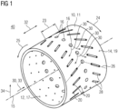
- the plain bearing bush 10 comprises a substantially cylindrical base body 11 which has a first outer surface 12 which is designed as an inner surface 17.
- the plain bearing bush 10 also has a second outer surface 14 which is designed as an outer surface 19.
- the plain bearing bush 10 can be used in a plain bearing 40, during the operation of which a rotary movement 25 takes place about a main axis of rotation 15.
- the main axis of rotation 15 also represents an axis of symmetry of the plain bearing bush 10.
- the plain bearing bush 10 is supplied with a lubricant 30 during operation of the plain bearing 40.
- the lubricant 30 is provided on the side of the first outer surface 12, i.e.
- the main bores 16 are formed substantially evenly spaced all the way around the plain bearing bush 10 in an axially central region 23. Spaced along an axial direction 32, the plain bearing bush 10 has a plurality of replacement bores 20, which have a smaller diameter overall than the main bores 16. The replacement bores 20 are also formed substantially evenly spaced in the circumferential direction 24. Furthermore, the replacement bores 16 are arranged in such a way that, in interaction with a main bore 16 each, they form an arrow pattern 26. Corresponding to the arrow pattern 28, two replacement bores 20 are connected to one another in pairs on the second lateral surface 14 by pocket recesses 28.
- the replacement bores 20 are designed to allow lubricant 30 to pass through in the radial direction 34, so that the second lateral surface 14 is wetted with lubricant 30.
- the Wetting of the second lateral surface 14 is supported by the pocket recesses 28.
- the first embodiment of the claimed plain bearing bush 10 is shown in a longitudinal section.
- At least one of the exchange bores 20 has a first diameter 27 on the first lateral surface 12, i.e. the inner side 17, into which the lubricant 30 enters during normal operation of the plain bearing 40.
- a flow speed 31 of the lubricant 30 is reduced.
- the differences in the flow speed 31 of the lubricant 30 are in FIG 2 symbolized by arrows of different lengths.
- the at least one replacement bore 20 has a countersink 36 in the region of the second lateral surface 14, by means of which a flow cross-section in the replacement bore 20 is increased, thus reducing the flow velocity 31.
- the first embodiment of the claimed plain bearing bush 10 according to FIG 1 and FIG 2 is in FIG 3 shown in a detailed view in a sectional view.
- the replacement bore 20 is designed as a countersink 36 and has an inlet section 35 with the first diameter 27 and an outlet section 39 adjacent to it or merging therein, which has a second diameter 29 in the area of the second lateral surface 14.
- the length 43 of the outlet section 39 corresponds to 10% to 100% of a bore length 41 of the replacement bore 20.
- the length 43 of the outlet section 39 essentially represents a dimension of the countersink 36 along the radial direction 34.
- Such a length 43 of the outlet section 39 causes a sufficient reduction in the flow speed 31 of the lubricant 30, by means of which a drag force 45 is set on the plain bearing bush 10 on the second lateral surface 14.
- the drag force 45 creates a drag effect by which the plain bearing bush 10 follows a rotary movement 25 of the plain bearing 40.
- the second diameter 39, the opening angle 37 and the length 43 of the outlet section 39 cause an increased drag force 45.
- the countersink 36 can be produced in a cost-effective manner using a countersink.
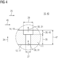
- FIG 4 A second embodiment of the claimed plain bearing bush 10 is shown in FIG 4 shown in a detailed view in a sectional view.
- the embodiment according to FIG 4 is also compatible with the embodiment according to FIG 1 , FIG 2 and FIG 3
- the replacement bore 20 is essentially designed as a stepped bore 38 and has an inlet section 35 with the first diameter 27 and an outlet section 39 with the second diameter 29 adjacent to it or merging therein.
- the length 43 of the outlet section 39 corresponds to 10% to 100% of a bore length 47 of the replacement bore 20.
- the length 43 of the outlet section 39 essentially represents a dimension of the stepped bore 38 along the radial direction 34.
- Such a length 43 of the outlet section 39 brings about a sufficient reduction in the flow velocity 31 of the lubricant 30, as a result of which a drag force 45 is exerted on the plain bearing bush 10 on the second jacket surface 14.
- the drag force 45 brings about a drag effect, as a result of which the plain bearing bush 10 follows a rotational movement 25 of the plain bearing 40.
- the second diameter 39 and the length 43 of the outlet section 39 cause an increased drag force 45.
- FIG 5 is a schematic cross-sectional view of an embodiment of a claimed plain bearing 40 which is used in a planetary gear 50 (not shown in detail).
- the plain bearing 40 comprises a planetary gear 46 as a rotating component 42 which is rotatably arranged on a planet carrier 55 of the planetary gear 50.
- the plain bearing 40 comprises an axle 48 as a stationary component 44 which is connected in a rotationally fixed manner to the planet carrier 55.
- stationary component 44, lubricant 30 is transported to the plain bearing 40 via a lubricant supply 33.
- the lubricant supply 44 is designed as lubricant channels, not shown in detail.
- the plain bearing 40 also comprises a plain bearing bush 10, which is designed as a floating bush 53.
- the plain bearing bush 10 is arranged between the stationary component 44 and the rotating component 42, so that a lubricating gap 49 can be formed between them in pairs.
- a rotary movement 25 of the rotating component 42 lubricant 30 is conveyed into an external lubricating gap 54 between the plain bearing bush 10 and the rotating component 42.
- a lubricating gap height 51 is established at the external lubricating gap 54.
- the plain bearing bush 10 is provided with exchange bores 20 through which lubricant 30 emerges in the region of the external lubricating gap 54. As a result, a drag force 45, i.e.
- a drag effect is exerted on the plain bearing bush 10, so that the plain bearing bush 10 follows the rotational movement 25 of the rotating component 42 more closely.
- the resulting sliding bush speed 18 is lower than a speed 21 of the rotating component 42.
- An internal lubrication gap 52 is formed between the stationary component 44 and the plain bearing bush 10, which has a lubrication gap height 51 depending on the sliding bush speed 21.
- the plain bearing bush 10 is provided with replacement bores 20, as in FIG 3 or FIG 4 shown, so that an increased drag force 45 is exerted on the plain bearing bush 10 in the external lubrication gap 54 during normal operation of the plain bearing 40.
- the lubricating film height 51 at the external lubrication gap 54 and/or at the internal lubrication gap 52 is increased.
- the load capacity 56 represents a measure of the amount of radial stresses 58 with which the plain bearing 40 can be loaded as intended.
- the loaded plain bearing bush 10 which is designed as a floating bush 53, increases the load capacity 56 of the plain bearing 40.
- the same The same effect as with the external lubrication gap 54 can also be achieved with the internal lubrication gap 52 if the flow direction of the lubricant 30 is temporarily reversed.
- the plain bearing bush 10 is also depicted in a computer program product 80 which is designed to simulate the operating behavior of the plain bearing bush 10 during operation of the plain bearing 40.
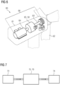
- FIG 6 shows in a sectional oblique view an embodiment of the claimed wind turbine 60, which comprises a nacelle 61 to which a multi-blade rotor 62 is rotatably mounted.
- a drive train 66 of the wind turbine 60 is accommodated in the nacelle 61, which comprises a main shaft 63, which is connected to the multi-blade rotor 62 in a torque-transmitting manner.
- the drive train 66 also comprises a generator 64, which is connected to the main shaft 63 in a torque-transmitting manner via a gear 65.
- the gear 65 is designed as a planetary gear 50 according to one of the embodiments described above.
- the industrial application 70 comprises an output unit 72, which can be designed, for example, as an electric motor, wind turbine, combustion engine or hydraulic motor.
- the drive unit 72 provides a drive power, i.e. a rotary motion 25, which is fed to a gear 75.
- the drive power is fed to an output unit 74.
- the output unit 84 can be designed, for example, as a mechanical application, so that the industrial application 70 is designed as a mill, vertical mill, sugar mill, cement mill, rock crusher, conveyor belt, pump, roller press, plate conveyor, tube mill, rotary kiln, rotating gear, agitator, agitator shredder, lifting device, garbage press or scrap press.
- the gear 75 via which the drive unit 72 is connected to the output unit 74, is designed as a planetary gear 50 designed according to one of the embodiments outlined above. Accordingly, the gear 75 is provided with at least one plain bearing 40 according to one of the embodiments shown above and has a plain bearing bush 10 according to at least one of the embodiments described above.
Landscapes
- Engineering & Computer Science (AREA)
- General Engineering & Computer Science (AREA)
- Mechanical Engineering (AREA)
- Life Sciences & Earth Sciences (AREA)
- Sustainable Energy (AREA)
- Chemical & Material Sciences (AREA)
- Sustainable Development (AREA)
- Power Engineering (AREA)
- Combustion & Propulsion (AREA)
- Oil, Petroleum & Natural Gas (AREA)
- Sliding-Contact Bearings (AREA)
Description
- Die Erfindung betrifft eine Gleitlagerbuchse, durch die eine Tragfähigkeit eines Gleitlagers steigerbar ist. Die Erfindung betrifft ebenso ein entsprechendes Gleitlager und ein Planetengetriebe, das mit einem solchen Gleitlager ausgestattet ist. Ferner betrifft die Erfindung eine Windkraftanlage und eine Industrie-Applikation, die jeweils über ein solches Planetengetriebe verfügen. Gleichermaßen betrifft die Erfindung ein Computerprogrammprodukt, mit dem das Betriebsverhalten einer entsprechenden Gleitlagerbuchse simulierbar ist.
- Die Druckschrift
DE 29 45 821 A1 offenbart ein Lager, das einen Lagerkörper umfasst, in dem drehbar eine schwimmende Buchse angeordnet ist. In der schwimmenden Buchse ist eine Welle drehbar aufgenommen. In der schwimmenden Buchse sind radial ausgerichtete Kanäle ausgebildet, durch die Öl zuführbar ist. Die Kanäle sind auf einer der Ölzufuhr zugewandten Seite geweitet ausgebildet. - Aus der Offenlegungsschrift
DE 35 37 449 A1 ist eine Lagerung mit schwimmenden Büchsen bekannt, die über radiale Bohrungen verfügen, über die Öl in Richtung einer drehbar gelagerten Welle zuführbar ist. Die radialen Bohrungen sind dabei an einem der Ölzufuhr zugewandten Ende geweitet ausgebildet. - Aus
US 4 371 219 A , welche den Oberbegriff des Anspruchs 1 offenbart, ist eine zylindrische Gleitlagerbuchse mit in radialer Richtung verlaufenden Austauschbohrungen für Schmierstoff bekannt, bei der die Austauschbohrungen an einer radial äußeren Mantelfläche der Gleitlagerbuchse einen größeren Durchmesser als an einer radial inneren Mantelfläche der Gleitlagerbuchse aufweisen. - Aus
CN 105 134 780 A ist eine zylindrische Gleitlagerbuchse mit in radialer Richtung verlaufenden Austauschbohrungen für Schmierstoff bekannt, bei der die Austauschbohrungen an einer radial inneren Mantelfläche der Gleitlagerbuchse einen größeren Durchmesser als an einer radial äußeren Mantelfläche der Gleitlagerbuchse aufweisen. - Aus
DE 10 2017 216 192 A1 ist ein Radialgleitlager zur Lagerung einer Welle bekannt, wobei das Radialgleitlager eine zylindrische Gleitlagerbuchse mit in radialer Richtung verlaufenden Austauschbohrungen für Schmierstoff aufweist. - Aus
DE 10 2017 223 390 A1 ist ein Radialgleitlager zur Lagerung einer Welle eines Getriebes für eine Windkraftanlage bekannt, wobei das Radialgleitlager eine zylindrische Gleitlagerbuchse aufweist. - Gleitlager werden in einer Vielzahl an Anwendungen eingesetzt, die eine hohe Lagertragfähigkeit, minimale Lagerreibungsverluste und hohe Lagerlebensdauer erfordern. Ebenso wird eine einfache und kosteneffiziente Herstellung solcher Gleitlager angestrebt. Es besteht Bedarf an einem Gleitlager, das in zumindest einer der beschriebenen Zielsetzungen eine Verbesserung bietet.
- Die Aufgabenstellung wird durch eine Gleitlagerbuchse mit den Merkmalen des Anspruch 1 gelöst. Bevorzugte Ausgestaltungen sind in den Unteransprüchen und der nachfolgenden Beschreibung angegeben, die jeweils einzeln oder in Kombination einen Aspekt der Erfindung darstellen können. Wenn ein Merkmal in Kombination mit einem anderen Merkmal dargestellt wird, dient dies nur der vereinfachten Darstellung der Erfindung und soll keinesfalls bedeuten, dass dieses Merkmal nicht auch ohne das andere Merkmal eine Weiterbildung der Erfindung sein kann.
- Die erfindungsgemäße Gleitlagerbuchse umfasst einen zylindrischen Grundkörper. Der zylindrische Grundkörper weist eine erste Mantelfläche und eine zweite Mantelfläche auf. Die erste und zweite Mantelfläche sind über eine Mehrzahl an Versorgungsbohrungen miteinander verbunden, so dass ein Schmierstoff durch eine Versorgungsbohrung von der ersten zur zweiten Mantelfläche und umgekehrt gelangen kann. Zumindest eine der Austauschbohrungen weist an der ersten Mantelfläche einen ersten Durchmesser auf und an einer zweiten Mantelfläche einen zweiten Durchmesser. Der Durchmesser ist dabei als eine Abmessung im Wesentlichen senkrecht zu einer Strömungsrichtung des Schmierstoffs zu verstehen. Der zweite Durchmesser ist größer als der erste Durchmesser. Dadurch ist eine Strömungsgeschwindigkeit des Schmierstoffs an der zweiten Mantelfläche geringer als an der ersten Mantelfläche. Ferner liegt in Bereichen der Austauschbohrungen mit dem zweiten Durchmesser ein erhöhter Strömungswiderstand vor. Infolgedessen liegt eine höhere Schleppwirkung des Schmierstoffs auf die Gleitlagerbuchse vor. Durch die gesteigerte Schleppwirkung wiederum ist eine gesteigerte Schmierspalthöhe erzielbar. Durch den zweiten Durchmesser, der größer ist als der erste Durchmesser, wird somit eine gesteigerte Tragfähigkeit des Gleitlagers erzielt, in dem die Gleitlagerbuchse einzusetzen ist. Austauschbohrungen mit unterschiedlichen Durchmessern an der ersten und zweiten Mantelfläche sind in einfacher Weise herstellbar. Durch die veränderte Geometrie wird die Schleppwirkung erhöht und die Tragfähigkeit gesteigert.
- Bei der beanspruchten Gleitlagerbuchse ist die zumindest eine Austauschbohrung axial versetzt zu einer Schmierstoffzufuhröffnung angeordnet. Unter einer Axialrichtung ist dabei eine Richtung im Wesentlichen parallel zu einer Hauptdrehachse der Gleitlagerbuchse zu verstehen. Die Schmierstoffzufuhröffnung ist in einer der Gleitlagerbuchse gegenüberliegenden Komponente des Gleitlagers ausgebildet. Schmierstoff, der durch die zumindest eine Austauschbohrung geleitet wird, fließt daher vor Erreichen der zumindest einen Austauschbohrung an der ersten Mantelfläche entlang. Die Austauschbohrungen sind dementsprechend derart angeordnet, dass Schmierstoff flächig auf der zweiten Mantelfläche abgegeben wird. Insbesondere können die Austauschbohrungen axial versetzt zu Hauptbohrungen sein, die einen größeren Durchmesser aufweisen als die Austauschbohrungen und die einer Schmierstoffzufuhröffnung im Wesentlichen gegenüberliegend angeordnet sind.
- Darüber hinaus sind mindestens zwei, insbesondere drei oder mehr, axial beabstandete Austauschbohrungen an der zweiten Mantelfläche, die insbesondere die Außenfläche des Grundkörpers darstellt, durch eine Taschenvertiefung miteinander verbunden. Im Bereich der Taschenvertiefung wird die Strömungsgeschwindigkeit des Schmierstoffs weiter verringert und stellt einen zusätzlichen Strömungswiderstand dar, so dass die Schleppwirkung auf die Gleitlagerbuchse weiter erhöht wird. Die Taschenvertiefungen können durch ein spanloses oder spanendes Bearbeitungsverfahren und/oder durch mechanische und/oder chemische Einwirkung erzeugt sein. Die Taschenvertiefungen können insbesondere durch Fräsen, Ätzen oder Erodieren hergestellt werden. Die Tragfähigkeit der beanspruchten Gleitlagerbuchse wird mittels der Taschenvertiefungen weiter gesteigert. Ferner können mehrere Taschenvertiefungen auf der zweiten Mantelfläche ausgebildet sein, die umlaufend zu einem Pfeilmuster oder Bogenmuster angeordnet sein können. Beispielsweise können die Taschenvertiefungen derart ausgerichtet sein, dass in einem mittleren Bereich der Gleitlagerbuchse auf der zweiten Mantelfläche eine Pfeilspitze angedeutet ist, die in oder gegen Umlaufrichtung weist. Das Pfeilmuster kann entlang einer bestimmungsgemäßen Drehrichtung der Gleitlagerbuchse oder entgegen dieser ausgebildet sein. Dadurch ist eine verbesserte Schmierstoffversorgung an der zweiten Mantelfläche erzielbar und ein gleichmäßiger Lauf der Gleitlagerbuchse gewährleistbar.
- Die Taschenvertiefungen könne beispielsweise als von der ersten Mantelfläche wegweisend geöffnete Rinne und/oder Nut ausgestaltet sein. Die Taschenvertiefung kann beispielsweise einen gerundeten, insbesondere im Wesentlichen U-förmigen, oder rechteckigen Strömungsquerschnitt in Richtung der über die Taschenvertiefung miteinander verbundenen Austauschbohrungen aufweisen. Beispielsweise verläuft die jeweilige Taschenvertiefung zur axialen Richtung und zur Umfangsrichtung des Grundkörpers auf einem im Wesentlichen konstanten Radius zu einer axialen Mittellinie des zylindrischen Grundkörpers angeschrägt. Insbesondere verlaufen zumindest ein Teil der in einem gemeinsamen Axialbereich des Grundkörpers vorgesehene Taschenvertiefungen, vorzugsweise sämtliche in dem gemeinsamen Axialbereich des Grundkörpers vorgesehene Taschenvertiefungen, in einer abgewickelten Darstellung des Grundkörpers parallel zueinander. In einer Ausführungsform der beanspruchten Gleitlagerbuchse sind zumindest zwei in Umfangsrichtung einander nachfolgen Taschenvertiefungen für einen Austausch von Schmiermittel miteinander verbunden. Die miteinander verbundenen Taschenvertiefungen können unter einer Winkel zueinander verlaufen, wobei insbesondere eine der Austauschbohrungen sowohl in der einen als auch in der anderen Taschenvertiefung einmündet, Vorzugsweise ist die gemeinsame Austauschbohrungen in einer Spitze eines gedachten Winkels der winkelig miteinander verbundenen Taschenvertiefungen positioniert. Dadurch ist es möglich, dass die miteinander verbundenen Taschenvertiefungen ein Zick-Zack-Muster ausbilden, das vorzugsweise in Umfangsrichtung geschlossen ausgeführt ist.
- In einer Ausführungsform der beanspruchten Gleitlagerbuchse ist die erste Mantelfläche eine Seite der Gleitlagerbuchse, die einer Schmierstoffzufuhr zugewandt ist. Dementsprechend ist die zweite Mantelfläche eine Seite der Gleitlagerbuchse, die der Schmierstoffzufuhr abgewandt ist. Im bestimmungsgemä-ßen Betrieb ist der Schmierstoff durch die Austauschbohrungen von der ersten zur zweiten Mantelfläche leitbar. An der zweiten Mantelfläche ist im bestimmungsgemäßen Betrieb eines Gleitlagers, das mit der beanspruchten Gleitlagerbuchse ausgestattet ist, der Schmierspalt des Gleitlagers ausgebildet. Durch den zweiten Durchmesser, der zumindest einen Austauschbohrung an der zweiten Mantelfläche wird im Schmierstoff ein Flüssigkeitswiderstand gesteigert, durch den mehr Schmierstoff in den Schmierspalt gefördert wird. Der Schmierspalt kann als Innenschmierspalt und/oder als Außenschmierspalt ausgebildet. Bei einem Innenschmierspalt und einem Außenschmierspalt wird die Schmierfilmhöhe in beiden gesteigert. Dadurch wird die Wirkung der beanspruchten Gleitlagerbuchse in gesteigertem Maße erzielt.
- Des Weiteren kann der zweite Durchmesser durch eine Ansenkung und/oder eine Stufenbohrung ausgebildet sein. Durch eine Ansenkung, die im Wesentlichen konusförmig ausgebildet ist, ist die Strömungsgeschwindigkeit des Schmierstoffs im Wesentlichen kontinuierlich verringerbar. Ansenkungen sind in einfacher Weise durch Kegelsenker präzise und kosteneffizient herstellbar. Eine Stufenbohrung, also eine Austauschbohrung mit abschnittsweise unterschiedlichen Durchmessern, ist ebenfalls schnell und kosteneffizient herstellbar. Bohrungen unterschiedlicher Durchmesser sind mit erhöhter Präzision herstellbar, so dass, abhängig von einem Verhältnis zwischen dem ersten und zweiten Durchmesser, eine Verringerung der Strömungsgeschwindigkeit des Schmierstoffs entsprechend präzise einstellbar ist. Die beanspruchte Gleitlagerbuchse ist somit in einfacher Weise an unterschiedliche Anwendungsfälle anpassbar. Ebenso können eine Ansenkung und eine Stufenbohrung kombiniert werden und so deren jeweilige Vorteile kombiniert zu erzielen.
- In einer weiteren Ausführungsform der beanspruchten Gleitlagerbuchse kann der zweite Durchmesser der Austauschbohrung dem 1,05-fachen bis 6,00-fachen des ersten Durchmessers entsprechen. Dadurch wird an der zweiten Mantelfläche eine vorteilhafte Verringerung der Strömungsgeschwindigkeit des Schmierstoffs erzielt, und ein Strömungswiderstand erzeugt. Dadurch wiederum wird eine entsprechende Steigerung der Schleppwirkung des Schmierstoffs auf die Gleitlagerbuchse hervorrufen. Gleichzeitig bietet ein entsprechender zweiter Durchmesser weiterhin einen ruhigen Lauf für die beanspruchte Gleitlagerbuchse.
- Ferner kann die beanspruchte Gleitlagerbuchse als Schwimmbuchse ausgebildet sein. Die Schwimmbuchse ist zwischen einer stationären und einer rotierenden Komponente des Gleitlagers angeordnet und bildet mit diesen einen Innenschmierspalt und einen Außenschmierspalt aus. Infolge der gesteigerten Schleppwirkung, die auf im bestimmungsgemäßen Betrieb die Gleitlagerbuchse ausgeübt wird, folgt dieser schneller einer Drehbewegung der rotierenden Komponente. Die Schmierspalthöhe im Innenschmierspalt und/oder im Außenschmierspalt wird so gesteigert, und damit auch die Tragfähigkeit des Gleitlagers. Dadurch, dass bei einer Schwimmbuchse ein Innenschmierspalt und ein Außenschmierspalt vorliegt, wird durch die beanspruchte Gleitlagerbuchse eine besonders gesteigerte Tragfähigkeit erzielt. Insbesondere wird die Dämpfungswirkung in den Schmierspalten verbessert und eine verbesserte Lastaufteilung bei Achsabstandsabweichungen erzielt. Ebenso wird ein verbesserten Anfahrverhalten nach Stillstand erreicht und die Temperatur im Betrieb reduziert.
- In einer weiteren Ausführungsform der beanspruchten Gleitlagerbuchse umfasst die zumindest eine Austauschbohrung einen Auslassabschnitt, der zumindest abschnittsweise den zweiten Durchmesser aufweist. Der Auslassabschnitt mündet an der zweiten Mantelfläche. Der Auslassabschnitt weist eine Länge auf, die 10% bis 100% einer Bohrlänge der Austauschbohrung ausmacht. Korrespondierend dazu umfasst die zumindest eine Austauschbohrung einen Einlassabschnitt, der sich ausgehend von der ersten Mantelfläche durch die Gleitlagerbuchse erstreckt und in den Auslassabschnitt übergeht bzw. an diesen angrenzt. Im Einlassabschnitt weist die zumindest eine Austauschbohrung den ersten Durchmesser auf. Je länger der Auslassabschnitt ist, umso stärker ist die Strömungsgeschwindigkeit des Schmierstoffs reduzierbar und gleichzeitig Wirbelbildung im Schmierstoff vermieden. Dementsprechend ist eine gleichmäßige Abgabe des Schmierstoffs an der zweiten Mantelfläche erreichbar. Dies gilt sowohl für Auslassabschnitte mit dem zweiten Durchmesser, die durch eine Ansenkung, also auch durch eine Stufenbohrung ausgebildet sind.
- Darüber hinaus kann die Ansenkung, durch die der zweite Durchmesser, der zumindest einen Austauschbohrung ausgebildet ist, einen Öffnungswinkel aufweisen, der 45° bis 135° beträgt. Dadurch wird eine besonders vorteilhafte Verringerung der Strömungsgeschwindigkeit des Schmierstoffs erreicht. Derartige Öffnungswinkel sind in einfacher Weise durch entsprechend geformte Kegelsenker schnelle und kosteneffizient herstellbar.
- Die zugrundeliegende Aufgabenstellung wird auch durch ein erfindungsgemäßes Gleitlager gelöst. Das Gleitlager umfasst eine rotierende Komponente, die drehbar an einer Gleitlagerbuchse angeordnet ist. Ebenfalls umfasst das Gleitlager eine stationäre Komponente. Die Gleitlagerbuchse ist erfindungsgemäß nach einer der oben dargestellten Ausführungsformen ausgebildet. Durch die Verwendung einer derartigen Gleitlagerbuchse weist das Gleitlager eine gesteigerte Tragfähigkeit auf. Insbesondere kann das beanspruchte Gleitlager eine Sommerfeldzahl von 0,10 bis 10,00 aufweisen. Das beanspruchte Gleitlager bietet damit eine Tragfähigkeit, und folglich auch eine Tragfähigkeitsreserve, die anspruchsvolle Einsatzgebiete erschließt, beispielsweise in Planetengetrieben von Gesteinsbrechern oder Zementmühlen.
- Des Weiteren wird die eingangs skizzierte Aufgabe durch ein erfindungsgemäßes Planetengetriebe gelöst. Das Planetengetriebe umfasst einen Planetenträger, an dem eine Mehrzahl an Planetenrädern drehbar angebracht ist. Die Planetenräder sind dabei jeweils mittels eines Gleitlagers drehbar am Planetenträger gelagert. Erfindungsgemäß ist zumindest eines der Gleitlager gemäß einer der oben dargestellten Ausführungsformen ausgebildet.
- Gleichermaßen wird die zugrundeliegende Aufgabenstellung durch eine erfindungsgemäße Windkraftanlage gelöst. Die Windkraftanlage umfasst eine Gondel, an der drehbar ein Mehrblattrotor angeordnet ist. In der Gondel ist ein Antriebsstrang angeordnet, zu dem ein Planetengetriebe gehört, das drehmomentübertragend mit dem Mehrblattrotor und einem Generator verbunden ist. Das Planetengetriebe ist erfindungsgemäß nach einer der oben angegebenen Ausführungsformen ausgebildet.
- Die Aufgabenstellung wird genauso durch eine erfindungsgemäße Industrie-Applikation gelöst, die eine Antriebseinheit und eine Abtriebseinheit umfasst. Die Antriebseinheit und die Abtriebseinheit sind über ein Planetengetriebe drehmomentübertragend miteinander verbunden. Die Antriebseinheit, ist beispielswiese als Elektromotor, Verbrennungsmotor oder Hydraulikmotor ausgebildet und stellt Antriebsleistung bereit, die über das Planetengetriebe zur Abtriebseinheit zu übertragen ist. Die Abtriebseinheit kann beispielsweise als Mühle, Vertikalmühle, Zuckermühle, Zementmühle, Gesteinsbrecher, Förderband, Pumpe, Rollenpresse, Plattenband, Rohrmühle, Drehrohrofen, Drehwerk, Rührwerk, Hubvorrichtung, Müllpresse oder Schrottpresse ausgebildet sein. Die Abtriebseinheit ist hierzu über das Planetengetriebe mit der Antriebseinheit verbunden. Das Getriebe ist erfindungsgemäß nach einer der oben skizzierten Ausführungsformen ausgebildet. Das erfindungsgemäße Planetengetriebe weist durch die beanspruchte Gleitlagerbuchse eine erhöhte Beanspruchbarkeit und Zuverlässigkeit auf. Dadurch ist der Wartungsaufwand für das Planetengetriebe verringert, was wiederum die Wirtschaftlichkeit der erfindungsgemäßen Industrie-Applikation steigert.
- Ebenso wird die eingangs beschriebene Aufgabe durch ein erfindungsgemäßes Computerprogrammprodukt mit den Merkmalen von Anspruch 15 gelöst, durch das ein Betriebsverhalten einer Gleitlagerbuchse in einem Gleitlager simulierbar ist. Dabei wird zumindest ein Schmierspalt, beispielsweise ein Innenschmierspalt und/oder ein Außenschmierspalt simuliert, der durch eine Drehbewegung am Gleitlager ausgebildet wird. Erfindungsgemäß wird dabei die vorliegende Schmierspalthöhe in Abhängigkeit vom vorliegenden Betriebszustand simuliert. Das Computerprogrammprodukt umfasst dazu lauffähige Simulationsroutinen für fluiddynamische Mechanismen und Datenschnittstellen, über die Betriebsparameter, wie eine Drehzahl, eine Temperatur des Schmierstoffs oder eine Radialbeanspruchung des Gleitlagers vorgebbar sind, oder ein nicht beanspruchtes Simulationsresultat ausgebbar ist. Das Computerprogrammprodukt umfasst einen Datensatz, durch den zumindest die Gleitlagerbuchse abgebildet ist. Mittels des erfindungsgemäßen Computerprogrammprodukts ist vorhersagbar oder zumindest plausibilisierbar, welche Tragfähigkeit im Gleitlager mit der Gleitlagerbuchse vorliegt. Ferner ist die erfindungsgemäße Gleitlagerbuchse in puncto Auslegung mittels des erfindungsgemäßen Computerprogrammprodukts anpassbar und das Gleitlager so ohne Weiteres optimierbar. Das Computerprogrammprodukt kann dazu beispielsweise als sogenannter Digitaler Zwilling ausgebildet sein. Derartige Digitale Zwillinge sind beispielsweise in der Offenlegungsschrift
US 2017/286572 A1 dargestellt. - Die Erfindung wird im Folgenden anhand einzelner Ausführungsformen in Figuren näher erläutert. Die Figuren sind insoweit in gegenseitiger Ergänzung zu lesen, dass gleiche Bezugszeichen in unterschiedlichen Figuren die gleiche technische Bedeutung haben. Die Merkmale der einzelnen Ausführungsformen sind untereinander auch kombinierbar. Ferner sind die in den Figuren gezeigten Ausführungsformen mit den oben skizzierten Merkmalen kombinierbar. Es zeigen im Einzelnen:
- FIG 1
- eine erste Ausführungsform der beanspruchten Gleitlagerbuchse in einer Schrägansicht;
- FIG 2
- die erste Ausführungsform der beanspruchten Gleitlagerbuchse im Längsschnitt;
- FIG 3
- die erste Ausführungsform der beanspruchten Gleitlagerbuchse in einer geschnittenen Detailansicht;
- FIG 4
- eine zweite Ausführungsform der beanspruchten Gleitlagerbuche in einer geschnittenen Detailansicht;
- FIG 5
- schematisch einen Aufbau einer Ausführungsform des beanspruchten Gleitlagers mit einer Gleitlagerbuchse in einer dritten Ausführungsform;
- FIG 6
- den Aufbau einer Ausführungsform der beanspruchten Windkraftanlage in einer geschnittenen Schrägansicht;
- FIG 7
- den Aufbau einer Ausführungsform der beanspruchten Industrie-Applikation.
- In
FIG 1 ist eine erste Ausführungsform der beanspruchten Gleitlagerbuchse 10 abgebildet. Die Gleitlagerbuchse 10 umfasst einen im Wesentlichen zylindrischen Grundkörper 11, der eine erste Mantelfläche 12 aufweist, die als Innenfläche 17 ausgebildet ist. Korrespondierend dazu weist die Gleitlagerbuchse 10 auch eine zweite Mantelfläche 14 auf, die als Außenfläche 19 ausgebildet ist. Die Gleitlagerbuchse 10 ist ein einem Gleitlager 40 einsetzbar, bei dessen Betrieb eine Drehbewegung 25 um eine Hauptdrehachse 15 erfolgt. Die Hauptdrehachse 15 stellt auch eine Symmetrieachse der Gleitlagerbuchse 10 dar. Die Gleitlagerbuchse 10 wird im Betrieb des Gleitlagers 40 mit einem Schmierstoff 30 versorgt. Der Schmierstoff 30 wird aufseiten der ersten Mantelfläche 12, also der Innenseite 17, über eine Schmierstoffzufuhr 33 bereitgestellt und über Hauptbohrungen 16 zur zweiten Mantelfläche 14, also die Außenfläche 19, transportiert. Die Hauptbohrungen 16 sind im Wesentlichen gleichmäßig beabstandet umlaufend an der Gleitlagerbuchse 10 in einem axial mittleren Bereich 23 ausgebildet. Entlang einer Axialrichtung 32 beabstandet weist die Gleitlagerbuchse 10 eine Mehrzahl an Austauschbohrungen 20 auf, die insgesamt geringere Durchmesser aufweisen als die Hauptbohrungen 16. Die Austauschbohrungen 20 sind auch in Umfangsrichtung 24 im Wesentlichen gleichmäßig beabstandet ausgebildet. Ferner sind die Austauschbohrungen 16 derart angeordnet, dass sie im Zusammenspiel mit je einer Hauptbohrung 16 ein Pfeilmuster 26 ausbilden. Korrespondierend zum Pfeilmuster 28 sind paarweise zwei Austauschbohrungen 20 an der zweiten Mantelfläche 14 durch Taschenvertiefungen 28 miteinander verbunden. Im Betrieb des Gleitlagers 40 sind die Austauschbohrungen 20 dazu ausgebildet, einen Durchtritt von Schmierstoff 30 in Radialrichtung 34 zu erlauben, so dass die zweite Mantelfläche 14 mit Schmierstoff 30 benetzt wird. Das Benetzen der zweiten Mantelfläche 14 wird durch die Taschenvertiefungen 28 unterstützt. - Ergänzend zu
FIG 1 ist inFIG 2 die erste Ausführungsform der beanspruchten Gleitlagerbuchse 10 in einem Längsschnitt dargestellt. Zumindest eine der Austauchbohrungen 20 weist an der ersten Mantelfläche 12, also der Innenseite 17, einen ersten Durchmesser 27 auf, in den der Schmierstoff 30 im bestimmungsgemäßen Betrieb des Gleitlagers 40 eintritt. An der zweiten Mantelfläche 14, also der Außenfläche 19, weist die zumindest eine Austauschbohrung 20 einen zweiten Durchmesser 29 auf, der größer ist als der erste Durchmesser 27. Beim Durchtritt durch die zumindest eine Austauschbohrung 20 wird eine Strömungsgeschwindigkeit 31 des Schmierstoffs 30 verringert. Die Unterschiede in der Strömungsgeschwindigkeit 31 des Schmierstoffs 30 sind inFIG 2 durch unterschiedlich lange Pfeile versinnbildlicht. Die zumindest eine Austauschbohrung 20 weist im Bereich der zweiten Mantelfläche 14 eine Ansenkung 36 auf, durch die ein Strömungsquerschnitt in der Austauschbohrung 20 erhöht wird, und so die Strömungsgeschwindigkeit 31 reduziert. - Die erste Ausführungsform der beanspruchten Gleitlagerbuchse 10 gemäß
FIG 1 undFIG 2 ist inFIG 3 in einer Detailansicht in einer Schnittdarstellung gezeigt. Die Austauschbohrung 20 ist als Ansenkung 36 ausgebildet weist einen Einlassabschnitt 35 mit dem erste Durchmesser 27 und einen daran angrenzenden bzw. darin übergehenden Auslassabschnitt 39 auf, der im Bereich der zweiten Mantelfläche 14 einen zweiten Durchmesser 29 aufweist. Die Länge 43 des Auslassabschnitts 39 entspricht 10% bis 100% einer Bohrlänge 41 der Austauschbohrung 20. Die Länge 43 des Auslassabschnitts 39 stellt im Wesentlichen eine Abmessung der Absenkung 36 entlang der Radialrichtung 34 dar. Eine derartige Länge 43 des Auslassabschnitts 39 wird eine hinreichende Verringerung der Strömungsgeschwindigkeit 31 des Schmierstoffs 30 hervorgerufen, durch den sich an der zweiten Mantelfläche 14 eine Schleppkraft 45 auf die Gleitlagerbuche 10 einstellt. Durch die Schleppkraft 45 wird eine Schleppwirkung hervorgerufen, durch die die Gleitlagerbuchse 10 einer Drehbewegung 25 des Gleitlagers 40 folgt. Durch den zweiten Durchmesser 39, den Öffnungswinkel 37 und die Länge 43 des Auslassabschnitts 39 wird eine erhöhte Schleppkraft 45 hervorgerufen. Die Ansenkung 36 ist mittels eines Kegelsenkers in kosteneffizienter Weise herstellbar. - Eine zweite Ausführungsform der beanspruchten Gleitlagerbuchse 10 ist in
FIG 4 in einer Detailansicht in einer Schnittdarstellung gezeigt. Die Ausführungsform nachFIG 4 ist auch mit der Ausführungsform nachFIG 1 ,FIG 2 undFIG 3 kombinierbar. Die Austauschbohrung 20 ist im Wesentlichen als Stufenbohrung 38 ausgebildet und weist einen Einlassabschnitt 35 mit dem ersten Durchmesser 27 und einen daran angrenzenden bzw. darin übergehenden Auslassabschnitt 39 mit dem zweiten Durchmesser 29 auf. Die Länge 43 des Auslassabschnitts 39 entspricht 10% bis 100% einer Bohrlänge 47 der Austauschbohrung 20. Die Länge 43 des Auslassabschnitts 39 stellt im Wesentlichen eine Abmessung der Stufenbohrung 38 entlang der Radialrichtung 34 dar. Eine derartige Länge 43 des Auslassabschnitts 39 wird eine hinreichende Verringerung der Strömungsgeschwindigkeit 31 des Schmierstoffs 30 hervorgerufen, durch den sich an der zweiten Mantelfläche 14 eine Schleppkraft 45 auf die Gleitlagerbuche 10 einstellt. Durch die Schleppkraft 45 wird eine Schleppwirkung hervorgerufen, durch die die Gleitlagerbuchse 10 einer Drehbewegung 25 des Gleitlagers 40 folgt. Durch den zweiten Durchmesser 39 und die Länge 43 des Auslassabschnitts 39 wird eine erhöhte Schleppkraft 45 hervorgerufen. - In
FIG 5 ist schematisch eine Ausführungsform eines beanspruchten Gleitlagers 40 im Querschnitt dargestellt, das in einem nicht näher gezeigten Planetengetriebe 50 eingesetzt wird. Das Gleitlager 40 umfasst als rotierende Komponente 42 ein Planetenrad 46, das drehbar an einem Planetenträger 55 des Planetengetriebes 50 angeordnet ist. Ferner umfasst das Gleitlager 40 als stationäre Komponente 44 eine Achse 48, die drehfest mit dem Planetenträger 55 verbunden ist. Durch die stationäre Komponente 44 wird Schmierstoff 30 über eine Schmierstoffzufuhr 33 zum Gleitlager 40 transportiert. Die Schmierstoffzufuhr 44 ist als nicht näher gezeigte Schmierstoffkanäle ausgebildet. Das Gleitlager 40 umfasst auch eine Gleitlagerbuchse 10, die als Schwimmbuchse 53 ausgebildet ist. Die Gleitlagerbuchse 10 ist zwischen der stationären Komponente 44 und der rotierenden Komponente 42 angeordnet, so dass sich zwischen diesen paarweise jeweils ein Schmierspalt 49 bildbar ist. Durch eine Drehbewegung 25 der rotierenden Komponente 42 wird Schmierstoff 30 in einen Außenschmierspalt 54 zwischen der Gleitlagerbuchse 10 und der rotierenden Komponente 42 gefördert. In Abhängigkeit von einer Geschwindigkeit der Drehbewegung 25 stellt sich am Außenschmierspalt 54 eine Schmierspalthöhe 51 ein. Die Gleitlagerbuchse 10 ist mit Austauschbohrungen 20 versehen, durch die Schmierstoff 30 im Bereich des Außenschmierspalts 54 austritt. Dadurch wird eine Schleppkraft 45, also ein Schleppwirkung, auf die Gleitlagerbuchse 10 ausgeübt, so dass die Gleitlagerbuchse 10 der Drehbewegung 25 der rotierenden Komponente 42 enger folgt. Die sich so ergebende Gleitbuchsendrehzahl 18 ist geringer als eine Drehzahl 21 der rotierenden Komponente 42. Zwischen der stationären Komponente 44 und der Gleitlagerbuchse 10 wird ein Innenschmierspalt 52 gebildet, der in Abhängigkeit von der Gleitbuchsendrehzahl 21 eine Schmierspalthöhe 51 aufweist. Die Gleitlagerbuchse 10 ist mit Austauschbohrungen 20, wie inFIG 3 oderFIG 4 dargestellt, versehen, so dass auf die Gleitlagerbuchse 10 im bestimmungsgemäßen Betrieb des Gleitlagers 40 eine gesteigerte Schleppkraft 45 im Außenschmierspalt 54 ausgeübt wird. Infolgedessen wird die Schmierfilmhöhe 51 am Außenschmierspalt 54 und/oder am Innenschmierspalt 52 erhöht. Je höher die Schmierspalthöhe 51 am Innenschmierspalt 52 und/oder am Außenschmierspalt 54 ist, umso höher ist eine Tragfähigkeit 56 des Gleitlagers 40. Die Tragfähigkeit 56 stellt ein Maß dafür dar, mit betragsmäßig welchen Radialbeanspruchungen 58 das Gleitlager 40 bestimmungsgemäß belastbar ist. Durch die beanspruchte Gleitlagerbuchse 10, die als Schwimmbuchse 53 ausgebildet ist, wird die Tragfähigkeit 56 des Gleitlagers 40 gesteigert. Die gleiche Wirkung, wie beim Außenschmierspalt 54, ist auch beim Innenschmierspalt 52 erzielbar, wenn die Strömungsrichtung des Schierstoffs 30 vorübergehend umgekehrt ist. Die Gleitlagerbuchse 10 ist ferner in einem Computerprogrammprodukt 80 abgebildet, das dazu ausgebildet ist, das Betriebsverhalten der Gleitlagerbuchse 10 im Betrieb des Gleitlagers 40 zu simulieren. -
FIG 6 zeigt in einer geschnittenen Schrägansicht eine Ausführungsform der beanspruchten Windkraftanlage 60, die eine Gondel 61 umfasst, an der ein Mehrblattrotor 62 drehbar angebracht ist. In der Gondel 61 ist ein Antriebsstrang 66 der Windkraftanlage 60 aufgenommen, der eine Hauptwelle 63 umfasst, die drehmomentübertragend mit dem Mehrblattrotor 62 verbunden ist. Der Antriebsstrang 66 umfasst auch einen Generator 64, der über ein Getriebe 65 drehmomentübertragend mit der Hauptwelle 63 verbunden ist. Das Getriebe 65 ist dabei als Planetengetriebe 50 gemäß einer der oben beschriebenen Ausführungsformen ausgebildet. - Eine Ausführungsform der beanspruchten Industrie-Applikation 70 ist in
FIG 7 schematisch dargestellt. Die Industrie-Applikation 70 umfasst eine Abtriebseinheit 72, die beispielsweise als Elektromotor, Windkraftanlage, Verbrennungsmotor oder Hydraulikmotor ausgebildet sein kann. Durch die Antriebseinheit 72 wird eine Antriebsleistung, also eine Drehbewegung 25, zur Verfügung gestellt, die einem Getriebe 75 zugeführt wird. Unter Wandlung der vorliegenden Drehzahl und des vorliegenden Drehmoments wird die Antriebsleistung einer Abtriebseinheit 74 zugeführt. Die Abtriebseinheit 84 kann beispielsweise als mechanische Anwendung ausgebildet sein, so dass die Industrie-Applikation 70 als Mühle, Vertikalmühle, Zuckermühle, Zementmühle, Gesteinsbrecher, Förderband, Pumpe, Rollenpresse, Plattenband, Rohrmühle, Drehrohrofen, Drehwerk, Rührwerk, Rührzerkleinerer, Hubvorrichtung, Müllpresse oder Schrottpresse ausgebildet ist. Erfindungsgemäß ist das Getriebe 75, über das die Antriebseinheit 72 mit der Abtriebseinheit 74 verbunden ist, Als Planetengetriebe 50 nach einer der oben skizzierten Ausführungsformen ausgebildet. Dementsprechend ist das Getriebe 75 mit zumindest einem Gleitlager 40 nach einer der oben dargestellten Ausführungsformen versehen und verfügt über eine Gleitlagerbuchse 10 gemäß zumindest einer der oben beschriebenen Ausführungsformen.
Claims (15)
- Gleitlagerbuchse (10), umfassend einen zylindrischen Grundkörper (11) mit einer ersten Mantelfläche (12) und einer zweiten Mantelfläche (14), der eine Mehrzahl an Austauschbohrungen (20) für einen Schmierstoff (30) aufweist, wobei zumindest eine der Austauschbohrungen (20) an der ersten Mantelfläche (12) einen ersten Durchmesser (27) aufweist und an der zweiten Mantelfläche (14) einen zweiten Durchmesser (29), wobei der zweite Durchmesser (29) zu einer Steigerung einer Tragfähigkeit (56) der Gleitlagerbuchse (10) größer ist als der erste Durchmesser (27), dadurch gekennze ichnet , dass zwei axial beabstandete Austauschbohrungen (20) an der zweiten Mantelfläche (14) durch eine Taschenvertiefung (28) miteinander verbunden sind.
- Gleitlagerbuchse (10) nach Anspruch 1, dadurch gekennzeichnet, dass die erste Mantelfläche (12) einer Schmierstoffzufuhr (33) zugewandte Seite der Gleitlagerbuchse (10) ist.
- Gleitlagerbuchse (10) nach Anspruch 1 oder 2, dadurch gekennzeichnet, dass der zweite Durchmesser (29) durch eine Ansenkung (36) und/oder eine Stufenbohrung (38) ausgebildet ist.
- Gleitlagerbuchse (10) nach Anspruch 3, dadurch g ekennzeichnet, dass die Ansenkung (36) einen Öffnungswinkel (37) von 45° bis 135° aufweist.
- Gleitlagerbuchse (10) nach einem der Ansprüche 1 bis 4, dadurch gekennzeichnet, dass die jeweilige Taschenvertiefung (28) zu einer axialen Richtung und zu einer Umfangsrichtung des Grundkörpers (11) auf einem im Wesentlichen konstanten Radius zu einer axialen Mittellinie des Grundkörpers (11) angeschrägt verläuft.
- Gleitlagerbuchse (10) nach einem der Ansprüche 1 bis 5, dadurch gekennzeichnet, dass mehrere Taschenvertiefungen (28) ausgebildet sind, die in einem umlaufenden Pfeilmuster (26) und/oder Zick-Zack-Muster angeordnet sind.
- Gleitlagerbuchse (10) nach einem der Ansprüche 1 bis 6, dadurch gekennzeichnet, dass der zweite Durchmesser (29) dem 1,05-fachen bis 6,00-fachen des ersten Durchmessers (27) entspricht.
- Gleitlagerbuchse (10) nach einem der Ansprüche 1 bis 7, dadurch gekennzeichnet, dass die Gleitlagerbuchse (10) als Schwimmbuchse (53) ausgebildet ist.
- Gleitlagerbuchse (10) nach einem der Ansprüche 1 bis 8, dadurch gekennzeichnet, dass ein Auslassabschnitt (39) mit dem zweiten Durchmesser (29) der zumindest einen Austauschbohrung (20) 10% bis 100% einer Bohrlänge (41) der zumindest einen Austauschbohrung (20) ausbildet.
- Gleitlager (40), umfassend eine stationäre Komponente (44), auf der eine Gleitlagerbuchse (10) nach einem der Ansprüche 1 bis 9 angeordnet ist, und eine rotierende Komponente (42), die drehbar auf der Gleitlagerbuchse (10) angebracht ist.
- Gleitlager (40) nach Anspruch 10, dadurch gekennzeichnet, dass das Gleitlager (40) eine Sommerfeldzahl von 0,10 bis 10,00 aufweist.
- Planetengetriebe (50), umfassend einen Planetenträger (55), in dem eine Mehrzahl an Planetenrädern (46) mittels jeweils eines Gleitlagers (40) nach Anspruch 10 oder 11 drehbar angeordnet ist.
- Windkraftanlage (60), umfassend eine Gondel (61), in der ein Getriebe (65) drehmomentübertragend mit einem Generator (64) verbunden ist, wobei das Getriebe (65) als Planetengetriebe (50) nach Anspruch 12 ausgebildet ist.
- Industrie-Applikation (70), umfassend eine Antriebseinheit (72) und eine Abtriebseinheit (74), die über ein Getriebe (75) miteinander verbunden sind, wobei das Getriebe (75) als Planetengetriebe (50) nach Anspruch 12 ausgebildet ist.
- Computerprogrammprodukt (80), umfassend Befehle, die bei der Ausführung des Programms durch einen Computer diesen verlassen, das Betriebsverhalten einer Gleitlagerbuchse (10) nach einem der Ansprüche 1 bis 9, die in einem Gleitlager (40) angeordnet ist, unter Ausführung der nachfolgenden Verfahrensschritte zu simulieren,wobei ein Innenschmierspalt (52) und/oder ein Außenschmierspalt (54) simuliert wird, der durch eine Drehbewegung am Gleitlager (40) ausgebildet wird,wobei die vorliegende Schmierspalthöhe in Abhängigkeit vom vorliegenden Betriebszustand simuliert wird,wobei das Computerprogrammprodukt (80) dazu lauffähige Simulationsroutinen für fluiddynamische Mechanismen und Datenschnittstellen umfasst, über die Betriebsparameter, wie eine Drehzahl, eine Temperatur des Schmierstoffs oder eine Radialbeanspruchung des Gleitlagers (40), vorgebbar sind,wobei das Computerprogrammprodukt (80) einen Datensatz umfasst, durch den die Gleitlagerbuchse (10) abgebildet ist und wobei mittels des Computerprogrammprodukts (80) die Tragfähigkeit im Gleitlager (40) mit der Gleitlagerbuchse (10) vorhersagbar ist.
Applications Claiming Priority (2)
| Application Number | Priority Date | Filing Date | Title |
|---|---|---|---|
| EP20198055.4A EP3974669A1 (de) | 2020-09-24 | 2020-09-24 | Gleitlagerbuchse für gleitlager mit gesteigerter tragfähigkeit |
| PCT/EP2021/075743 WO2022063710A1 (de) | 2020-09-24 | 2021-09-20 | Gleitlagerbuchse für gleitlager mit gesteigerter tragfähigkeit |
Publications (3)
| Publication Number | Publication Date |
|---|---|
| EP4217618A1 EP4217618A1 (de) | 2023-08-02 |
| EP4217618B1 true EP4217618B1 (de) | 2024-08-28 |
| EP4217618C0 EP4217618C0 (de) | 2024-08-28 |
Family
ID=72644166
Family Applications (2)
| Application Number | Title | Priority Date | Filing Date |
|---|---|---|---|
| EP20198055.4A Withdrawn EP3974669A1 (de) | 2020-09-24 | 2020-09-24 | Gleitlagerbuchse für gleitlager mit gesteigerter tragfähigkeit |
| EP21778454.5A Active EP4217618B1 (de) | 2020-09-24 | 2021-09-20 | Gleitlagerbuchse für gleitlager mit gesteigerter tragfähigkeit |
Family Applications Before (1)
| Application Number | Title | Priority Date | Filing Date |
|---|---|---|---|
| EP20198055.4A Withdrawn EP3974669A1 (de) | 2020-09-24 | 2020-09-24 | Gleitlagerbuchse für gleitlager mit gesteigerter tragfähigkeit |
Country Status (4)
| Country | Link |
|---|---|
| US (1) | US11852190B2 (de) |
| EP (2) | EP3974669A1 (de) |
| CN (1) | CN116348685B (de) |
| WO (1) | WO2022063710A1 (de) |
Families Citing this family (2)
| Publication number | Priority date | Publication date | Assignee | Title |
|---|---|---|---|---|
| CN116044687B (zh) * | 2023-02-02 | 2026-03-20 | 青岛盘古智能制造股份有限公司 | 一种风力发电机组偏航润滑控制机构及系统 |
| CN117249172B (zh) * | 2023-10-13 | 2024-04-09 | 浙江中达精密部件股份有限公司 | 一种用于风电设备的滑动轴承系统 |
Citations (3)
| Publication number | Priority date | Publication date | Assignee | Title |
|---|---|---|---|---|
| EP2383480A1 (de) * | 2010-04-30 | 2011-11-02 | Winergy AG | Planetengetriebe für eine Windkraftanlage |
| EP3306142A1 (de) * | 2016-10-05 | 2018-04-11 | Flender GmbH | Lagerung für ein planetenrad eines planetengetriebes |
| EP3406941A1 (de) * | 2017-05-24 | 2018-11-28 | Siemens Aktiengesellschaft | Stirnradanordnung, getriebe und windenergieanlage |
Family Cites Families (13)
| Publication number | Priority date | Publication date | Assignee | Title |
|---|---|---|---|---|
| FR751198A (fr) * | 1933-02-21 | 1933-08-28 | Nouveau système de palier | |
| JPS5565723A (en) | 1978-11-14 | 1980-05-17 | Nissan Motor Co Ltd | Lubricating configuration of floating bush |
| DE3537449A1 (de) | 1985-10-22 | 1987-01-02 | Mtu Friedrichshafen Gmbh | Lagerung mit schwimmenden buechsen |
| DE19713366C1 (de) * | 1997-04-02 | 1998-10-15 | Joerg Vogelsang Gmbh & Co | Spannbuchse |
| KR20110071928A (ko) * | 2009-12-22 | 2011-06-29 | 두산인프라코어 주식회사 | 부시타입 베어링 및 그 제조방법 |
| US10087920B2 (en) * | 2014-05-16 | 2018-10-02 | Quincy Compressor Llc | Compressor bushing |
| CN105134780A (zh) * | 2015-06-25 | 2015-12-09 | 重庆德蚨乐机械制造有限公司 | 增压器及其浮动轴承 |
| US20170286572A1 (en) | 2016-03-31 | 2017-10-05 | General Electric Company | Digital twin of twinned physical system |
| EP3464916B1 (de) * | 2016-05-26 | 2021-10-20 | Flender-Graffenstaden S.A.S. | Hydrodynamisches lager mit injektoren und deflektoren |
| US10465604B2 (en) * | 2017-03-10 | 2019-11-05 | GM Global Technology Operations LLC | Turbocharger for a vehicle engine |
| US20180283269A1 (en) * | 2017-03-29 | 2018-10-04 | GM Global Technology Operations LLC | Turbocharger for a vehicle engine |
| DE102017216192A1 (de) * | 2017-09-13 | 2019-03-14 | Zf Friedrichshafen Ag | Radialgleitlager mit optimierter Schmierdruckverteilung |
| DE102017223390A1 (de) * | 2017-12-20 | 2019-06-27 | Zf Friedrichshafen Ag | Gleitlageranordnung für eine schwere Welle, insbesondere einer Windkraftanlage, sowie Steuersystem und Verfahren zur Betriebssteuerung derselben |
-
2020
- 2020-09-24 EP EP20198055.4A patent/EP3974669A1/de not_active Withdrawn
-
2021
- 2021-09-20 EP EP21778454.5A patent/EP4217618B1/de active Active
- 2021-09-20 US US18/025,120 patent/US11852190B2/en active Active
- 2021-09-20 WO PCT/EP2021/075743 patent/WO2022063710A1/de not_active Ceased
- 2021-09-20 CN CN202180065471.9A patent/CN116348685B/zh active Active
Patent Citations (3)
| Publication number | Priority date | Publication date | Assignee | Title |
|---|---|---|---|---|
| EP2383480A1 (de) * | 2010-04-30 | 2011-11-02 | Winergy AG | Planetengetriebe für eine Windkraftanlage |
| EP3306142A1 (de) * | 2016-10-05 | 2018-04-11 | Flender GmbH | Lagerung für ein planetenrad eines planetengetriebes |
| EP3406941A1 (de) * | 2017-05-24 | 2018-11-28 | Siemens Aktiengesellschaft | Stirnradanordnung, getriebe und windenergieanlage |
Also Published As
| Publication number | Publication date |
|---|---|
| EP3974669A1 (de) | 2022-03-30 |
| US11852190B2 (en) | 2023-12-26 |
| CN116348685A (zh) | 2023-06-27 |
| EP4217618A1 (de) | 2023-08-02 |
| WO2022063710A1 (de) | 2022-03-31 |
| CN116348685B (zh) | 2025-11-18 |
| EP4217618C0 (de) | 2024-08-28 |
| US20230304531A1 (en) | 2023-09-28 |
Similar Documents
| Publication | Publication Date | Title |
|---|---|---|
| AT513507B1 (de) | Gleitlagerpaket | |
| DE19902565B4 (de) | Anlaufscheibe eines Planetentriebes | |
| EP3001071B1 (de) | Öldurchbohrung Planetensteg | |
| EP3794244B1 (de) | Doppelkupplungseinheit und antriebsanordnung mit einer solchen doppelkupplungseinheit | |
| EP2387664A2 (de) | Windkraftanlage | |
| EP3488125B2 (de) | Lagerung für ein planetenrad eines planetengetriebes | |
| EP4217618B1 (de) | Gleitlagerbuchse für gleitlager mit gesteigerter tragfähigkeit | |
| EP3091242A1 (de) | Gleitlager mit schmiernut | |
| EP3798470A1 (de) | Planetengetriebe mit verbesserter schmierstoffversorgung, antriebsstrang und windkraftanlage | |
| EP4200543B1 (de) | Planetengetriebe mit verbesserter schmierstoffübergabe, antriebsstrang, windkraftanlage und industrie-applikation | |
| EP3093514A1 (de) | Radialgleitlager mit versetzten schmiertaschen | |
| EP3536993A1 (de) | Gleitlagersystem, planetengetriebe, windkraftanlage und industrieanwendung | |
| DE102022111081B4 (de) | Käfig für ein Wälzlager, Wälzlager mit einem Käfig sowie Planetengetriebe mit einem Wälzlager | |
| EP4043756A1 (de) | Planetenträgeranordnung, planetengetriebe, antriebsstrang, windkraftanlage und computerprogrammprodukt | |
| EP0761968A1 (de) | Kreiskolbenmaschine mit hydrostatisch gelagertem Steuerteil und Steuerteil dafür | |
| EP4638951B1 (de) | Antriebsstranglagerung für planetengetriebe | |
| EP3795863A1 (de) | Baureihe von planetengetrieben, windkraftanlage, industrie-applikation und verwendung von wälzlagern | |
| DE102022111082B3 (de) | Ringförmige Anlaufscheibe, Planetengetriebe mit einer solchen Anlaufscheibe sowie Schmiervorrichtung für ein Planetengetriebe | |
| DE102022111079B4 (de) | Ringförmige Anlaufscheibe, Planetengetriebe mit einer solchen Anlaufscheibe sowie Schmiervorrichtung für ein Planetengetriebe | |
| WO2003085284A1 (de) | Gleitlagerung von ritzeln auf drehbaren wellen für ein getriebe | |
| EP4513061A1 (de) | Verschleissarmes getriebe | |
| EP4481239A1 (de) | Anlaufscheibe zum verteilen einer flüssigkeit mit schmiermitteltaschen | |
| DE102021111774A1 (de) | Wälzlageranordnung | |
| EP3453917B1 (de) | Zugmitteltrieb für ein kraftfahrzeuggetriebe | |
| EP4530500A1 (de) | Welle-nabe-verbindung mit verschleissoptimierter schicht |
Legal Events
| Date | Code | Title | Description |
|---|---|---|---|
| STAA | Information on the status of an ep patent application or granted ep patent |
Free format text: STATUS: UNKNOWN |
|
| STAA | Information on the status of an ep patent application or granted ep patent |
Free format text: STATUS: THE INTERNATIONAL PUBLICATION HAS BEEN MADE |
|
| PUAI | Public reference made under article 153(3) epc to a published international application that has entered the european phase |
Free format text: ORIGINAL CODE: 0009012 |
|
| STAA | Information on the status of an ep patent application or granted ep patent |
Free format text: STATUS: REQUEST FOR EXAMINATION WAS MADE |
|
| 17P | Request for examination filed |
Effective date: 20230406 |
|
| AK | Designated contracting states |
Kind code of ref document: A1 Designated state(s): AL AT BE BG CH CY CZ DE DK EE ES FI FR GB GR HR HU IE IS IT LI LT LU LV MC MK MT NL NO PL PT RO RS SE SI SK SM TR |
|
| DAV | Request for validation of the european patent (deleted) | ||
| DAX | Request for extension of the european patent (deleted) | ||
| GRAP | Despatch of communication of intention to grant a patent |
Free format text: ORIGINAL CODE: EPIDOSNIGR1 |
|
| STAA | Information on the status of an ep patent application or granted ep patent |
Free format text: STATUS: GRANT OF PATENT IS INTENDED |
|
| INTG | Intention to grant announced |
Effective date: 20240319 |
|
| GRAJ | Information related to disapproval of communication of intention to grant by the applicant or resumption of examination proceedings by the epo deleted |
Free format text: ORIGINAL CODE: EPIDOSDIGR1 |
|
| STAA | Information on the status of an ep patent application or granted ep patent |
Free format text: STATUS: REQUEST FOR EXAMINATION WAS MADE |
|
| INTC | Intention to grant announced (deleted) | ||
| GRAP | Despatch of communication of intention to grant a patent |
Free format text: ORIGINAL CODE: EPIDOSNIGR1 |
|
| STAA | Information on the status of an ep patent application or granted ep patent |
Free format text: STATUS: GRANT OF PATENT IS INTENDED |
|
| GRAS | Grant fee paid |
Free format text: ORIGINAL CODE: EPIDOSNIGR3 |
|
| GRAA | (expected) grant |
Free format text: ORIGINAL CODE: 0009210 |
|
| STAA | Information on the status of an ep patent application or granted ep patent |
Free format text: STATUS: THE PATENT HAS BEEN GRANTED |
|
| INTG | Intention to grant announced |
Effective date: 20240715 |
|
| AK | Designated contracting states |
Kind code of ref document: B1 Designated state(s): AL AT BE BG CH CY CZ DE DK EE ES FI FR GB GR HR HU IE IS IT LI LT LU LV MC MK MT NL NO PL PT RO RS SE SI SK SM TR |
|
| REG | Reference to a national code |
Ref country code: CH Ref legal event code: EP |
|
| REG | Reference to a national code |
Ref country code: DE Ref legal event code: R096 Ref document number: 502021004985 Country of ref document: DE |
|
| REG | Reference to a national code |
Ref country code: IE Ref legal event code: FG4D Free format text: LANGUAGE OF EP DOCUMENT: GERMAN |
|
| U01 | Request for unitary effect filed |
Effective date: 20240828 |
|
| U07 | Unitary effect registered |
Designated state(s): AT BE BG DE DK EE FI FR IT LT LU LV MT NL PT RO SE SI Effective date: 20240903 |
|
| U20 | Renewal fee for the european patent with unitary effect paid |
Year of fee payment: 4 Effective date: 20240925 |
|
| PG25 | Lapsed in a contracting state [announced via postgrant information from national office to epo] |
Ref country code: NO Free format text: LAPSE BECAUSE OF FAILURE TO SUBMIT A TRANSLATION OF THE DESCRIPTION OR TO PAY THE FEE WITHIN THE PRESCRIBED TIME-LIMIT Effective date: 20241128 |
|
| PG25 | Lapsed in a contracting state [announced via postgrant information from national office to epo] |
Ref country code: GR Free format text: LAPSE BECAUSE OF FAILURE TO SUBMIT A TRANSLATION OF THE DESCRIPTION OR TO PAY THE FEE WITHIN THE PRESCRIBED TIME-LIMIT Effective date: 20241129 Ref country code: PL Free format text: LAPSE BECAUSE OF FAILURE TO SUBMIT A TRANSLATION OF THE DESCRIPTION OR TO PAY THE FEE WITHIN THE PRESCRIBED TIME-LIMIT Effective date: 20240828 |
|
| PG25 | Lapsed in a contracting state [announced via postgrant information from national office to epo] |
Ref country code: IS Free format text: LAPSE BECAUSE OF FAILURE TO SUBMIT A TRANSLATION OF THE DESCRIPTION OR TO PAY THE FEE WITHIN THE PRESCRIBED TIME-LIMIT Effective date: 20241228 |
|
| PG25 | Lapsed in a contracting state [announced via postgrant information from national office to epo] |
Ref country code: HR Free format text: LAPSE BECAUSE OF FAILURE TO SUBMIT A TRANSLATION OF THE DESCRIPTION OR TO PAY THE FEE WITHIN THE PRESCRIBED TIME-LIMIT Effective date: 20240828 |
|
| PG25 | Lapsed in a contracting state [announced via postgrant information from national office to epo] |
Ref country code: RS Free format text: LAPSE BECAUSE OF FAILURE TO SUBMIT A TRANSLATION OF THE DESCRIPTION OR TO PAY THE FEE WITHIN THE PRESCRIBED TIME-LIMIT Effective date: 20241128 Ref country code: ES Free format text: LAPSE BECAUSE OF FAILURE TO SUBMIT A TRANSLATION OF THE DESCRIPTION OR TO PAY THE FEE WITHIN THE PRESCRIBED TIME-LIMIT Effective date: 20240828 |
|
| PG25 | Lapsed in a contracting state [announced via postgrant information from national office to epo] |
Ref country code: RS Free format text: LAPSE BECAUSE OF FAILURE TO SUBMIT A TRANSLATION OF THE DESCRIPTION OR TO PAY THE FEE WITHIN THE PRESCRIBED TIME-LIMIT Effective date: 20241128 Ref country code: PL Free format text: LAPSE BECAUSE OF FAILURE TO SUBMIT A TRANSLATION OF THE DESCRIPTION OR TO PAY THE FEE WITHIN THE PRESCRIBED TIME-LIMIT Effective date: 20240828 Ref country code: NO Free format text: LAPSE BECAUSE OF FAILURE TO SUBMIT A TRANSLATION OF THE DESCRIPTION OR TO PAY THE FEE WITHIN THE PRESCRIBED TIME-LIMIT Effective date: 20241128 Ref country code: IS Free format text: LAPSE BECAUSE OF FAILURE TO SUBMIT A TRANSLATION OF THE DESCRIPTION OR TO PAY THE FEE WITHIN THE PRESCRIBED TIME-LIMIT Effective date: 20241228 Ref country code: HR Free format text: LAPSE BECAUSE OF FAILURE TO SUBMIT A TRANSLATION OF THE DESCRIPTION OR TO PAY THE FEE WITHIN THE PRESCRIBED TIME-LIMIT Effective date: 20240828 Ref country code: GR Free format text: LAPSE BECAUSE OF FAILURE TO SUBMIT A TRANSLATION OF THE DESCRIPTION OR TO PAY THE FEE WITHIN THE PRESCRIBED TIME-LIMIT Effective date: 20241129 Ref country code: ES Free format text: LAPSE BECAUSE OF FAILURE TO SUBMIT A TRANSLATION OF THE DESCRIPTION OR TO PAY THE FEE WITHIN THE PRESCRIBED TIME-LIMIT Effective date: 20240828 |
|
| PG25 | Lapsed in a contracting state [announced via postgrant information from national office to epo] |
Ref country code: SM Free format text: LAPSE BECAUSE OF FAILURE TO SUBMIT A TRANSLATION OF THE DESCRIPTION OR TO PAY THE FEE WITHIN THE PRESCRIBED TIME-LIMIT Effective date: 20240828 |
|
| PG25 | Lapsed in a contracting state [announced via postgrant information from national office to epo] |
Ref country code: CZ Free format text: LAPSE BECAUSE OF FAILURE TO SUBMIT A TRANSLATION OF THE DESCRIPTION OR TO PAY THE FEE WITHIN THE PRESCRIBED TIME-LIMIT Effective date: 20240828 |
|
| PG25 | Lapsed in a contracting state [announced via postgrant information from national office to epo] |
Ref country code: SK Free format text: LAPSE BECAUSE OF FAILURE TO SUBMIT A TRANSLATION OF THE DESCRIPTION OR TO PAY THE FEE WITHIN THE PRESCRIBED TIME-LIMIT Effective date: 20240828 |
|
| REG | Reference to a national code |
Ref country code: CH Ref legal event code: PL |
|
| PLBE | No opposition filed within time limit |
Free format text: ORIGINAL CODE: 0009261 |
|
| STAA | Information on the status of an ep patent application or granted ep patent |
Free format text: STATUS: NO OPPOSITION FILED WITHIN TIME LIMIT |
|
| PG25 | Lapsed in a contracting state [announced via postgrant information from national office to epo] |
Ref country code: MC Free format text: LAPSE BECAUSE OF FAILURE TO SUBMIT A TRANSLATION OF THE DESCRIPTION OR TO PAY THE FEE WITHIN THE PRESCRIBED TIME-LIMIT Effective date: 20240828 |
|
| PG25 | Lapsed in a contracting state [announced via postgrant information from national office to epo] |
Ref country code: CH Free format text: LAPSE BECAUSE OF NON-PAYMENT OF DUE FEES Effective date: 20240930 |
|
| PG25 | Lapsed in a contracting state [announced via postgrant information from national office to epo] |
Ref country code: IE Free format text: LAPSE BECAUSE OF NON-PAYMENT OF DUE FEES Effective date: 20240920 |
|
| 26N | No opposition filed |
Effective date: 20250530 |
|
| U20 | Renewal fee for the european patent with unitary effect paid |
Year of fee payment: 5 Effective date: 20250917 |
|
| PG25 | Lapsed in a contracting state [announced via postgrant information from national office to epo] |
Ref country code: CY Free format text: LAPSE BECAUSE OF FAILURE TO SUBMIT A TRANSLATION OF THE DESCRIPTION OR TO PAY THE FEE WITHIN THE PRESCRIBED TIME-LIMIT; INVALID AB INITIO Effective date: 20210920 |
|
| PG25 | Lapsed in a contracting state [announced via postgrant information from national office to epo] |
Ref country code: HU Free format text: LAPSE BECAUSE OF FAILURE TO SUBMIT A TRANSLATION OF THE DESCRIPTION OR TO PAY THE FEE WITHIN THE PRESCRIBED TIME-LIMIT; INVALID AB INITIO Effective date: 20210920 |