EP4217134B1 - Oscillating table and assembly method thereof - Google Patents
Oscillating table and assembly method thereof Download PDFInfo
- Publication number
- EP4217134B1 EP4217134B1 EP21790997.7A EP21790997A EP4217134B1 EP 4217134 B1 EP4217134 B1 EP 4217134B1 EP 21790997 A EP21790997 A EP 21790997A EP 4217134 B1 EP4217134 B1 EP 4217134B1
- Authority
- EP
- European Patent Office
- Prior art keywords
- elastic
- central portion
- elastic bar
- fixed frame
- oscillating structure
- Prior art date
- Legal status (The legal status is an assumption and is not a legal conclusion. Google has not performed a legal analysis and makes no representation as to the accuracy of the status listed.)
- Active
Links
Images


Classifications
-
- B—PERFORMING OPERATIONS; TRANSPORTING
- B22—CASTING; POWDER METALLURGY
- B22D—CASTING OF METALS; CASTING OF OTHER SUBSTANCES BY THE SAME PROCESSES OR DEVICES
- B22D11/00—Continuous casting of metals, i.e. casting in indefinite lengths
- B22D11/04—Continuous casting of metals, i.e. casting in indefinite lengths into open-ended moulds
- B22D11/053—Means for oscillating the moulds
Definitions
- the present invention relates to an oscillating table, in particular a table used in plants for the production of billets, blooms, or other steel semi-finished products to allow the oscillation of the crystallizer inserted in an ingot mold in order to carry out the casting process.
- the invention further relates to an assembly method of the oscillating table.
- the oscillating table as e.g. described in CN 101 342 582 A or CN 202 224 616 U , is an element, known in the steelworks industry, which sets the ingot mold in oscillating motion, and thus the crystallizer contained therein, into which the casting takes place.
- the repetitive motion of the oscillating table serves to prevent the skin of the product from sticking to the walls of the crystallizer. Said skin is formed due to the heat exchange between the liquid steel and the walls of the crystallizer which is externally cooled.
- the lubricating effect can also be increased by the introduction of lubricating powders, which are inserted between the skin of the product and the walls of the crystallizer.
- the oscillating table is characterized by the presence of one or more actuators which impose a determined stroke on the movable structure or oscillating stand of the table, based on a periodic, generally sinusoidal, oscillation.
- the required stroke and oscillation will vary according to the casting speed, the cast material, and other operating parameters.
- Another fundamental parameter for the correct casting of different products is the casting radius of the machine, which is defined in the initial designing step according to the combination of geometries and dimensions of the set of products that the machine will have to cast.
- Another aspect of the invention relates to an assembly method of the aforesaid oscillating table in which it is provided that each first elastic bar and each second elastic bar is housed within a respective hollow housing, the two ends of each first elastic bar and each second elastic bar being fixed in a pretensioned manner within corresponding ends of the respective hollow housing; the method comprising the following steps:
- the central portion of the first and second elastic bars is maintained always at a respective portion of the oscillating structure, preferably at a respective locking device, only the inclination of said elastic bars being adjusted.
- the ends of the hollow housing, containing the respective pretensioned elastic bar, can be removably fixed in fixed positions on the support fixed frame; this allows for quick assembly, even directly in the casting area, without the need for alignment in the tooling workshop.
- predetermined holes can be provided on the fixed frame for fixing the ends of the hollow housings, said predetermined holes corresponding to different inclinations of the first and second elastic bars, and thus to different casting radii.
- hollow housings of the first and second elastic bars all have the same length, as well as the pretensioned elastic bars inside said hollow housings, makes it easy to arrange their fixing to the fixed frame.
- the figures show an oscillating table, object of the present invention, comprising:
- Said elastic means comprise, in all embodiments of the invention, two first elastic bars 5, 5' and two second elastic bars 6, 6', defining a respective axis, having two respective ends fixed indirectly to the support fixed frame 1, and having a respective central portion 7 constrained to the oscillating structure 2.
- the two first elastic bars 5, 5' are arranged parallel to each other, being positioned at a first side and at a second side of said support fixed frame 1, respectively, said first side and said second side being parallel to each other and equally spaced apart from said casting direction X. Also, the second elastic bars 6, 6' are arranged parallel to each other, being respectively positioned at said first side and at said second side, below the first elastic bars 5, 5' ( Figure 2 ).
- the first elastic bars 5, 5' are inclined, in an adjustable manner, by a first acute angle with respect to a horizontal plane, while the second elastic bars 6, 6' are inclined, in an adjustable manner, by a second acute angle, different from said first acute angle, with respect to said horizontal plane, whereby the two ideal intersection points between the axes of the first elastic bars and the corresponding axes of the underlying second elastic bars define an ideal oscillation axis Y about which the oscillating structure 2 can oscillate ( Figure 1 ).
- a casting radius R is also shown in Figure 1 .
- both the first elastic bars 5, 5' and the second elastic bars 6, 6' are arranged symmetrically with respect to a plane containing the casting direction X ( Figure 2 ).
- the first acute angle of inclination of the first elastic bars 5, 5' and the second acute angle of inclination of the second elastic bars 6, 6' have the same sign with respect to the horizontal plane containing the ideal oscillation axis Y ( Figure 1 ).
- the first acute angle and the second acute angle are of opposite sign with respect to the horizontal plane containing the ideal oscillation axis Y.
- the oscillating structure 2 is provided with a plurality of locking devices 20, one locking device 20 for each of the first elastic bars 5, 5' and the second elastic bars 6, 6'.
- each locking device 20 comprises, preferably consists of ( Figure 3 ):
- the first part 21, e.g. in the form of a protruding pin, is fixed to the oscillating structure 2 so that said first part can rotate about its own axis Z.
- the end face of the pin, distal from the oscillating structure 2 is provided with a groove 23 in which the central portion 7 of the respective elastic bar 5, 5', 6, 6' can be fitted.
- the second part 22 of the locking device e.g., in the form of a fixing flange, is applied to the first part 21, locking in position both the central portion 7, and thus the elastic bar, and the first part 21 of the device.
- the second part 22 can be fixed to the first part 21 of the locking device 20 and to the oscillating structure 2 by means of a plurality of fixing means, such as screws, which cross the first part 21 completely.
- the second part 22 can be fixed to the first part 21 by means of a plurality of first fixing means, such as screws 24, while the first part 21 can be fixed to the oscillating structure 2 by means of a plurality of second fixing means, such as screws 25.
- a fixing flange 26 is provided which constitutes a base of the first part 21, the latter being in the form of a pin protruding from said base.
- the first part 21, e.g., in the form of a protruding pin, is integrally fixed to the oscillating structure 2.
- the end face of the pin, distal from the oscillating structure 2 is provided with a groove 23 in which the central portion 7 of the respective elastic bar 5, 5', 6, 6' can be inserted.
- a clearance is provided between the groove 23 and said central portion 7 which allows the operator to adjust the angle of inclination of the elastic bar.
- the second part 22 of the locking device e.g., in the form of a fixing flange
- the first part 21 can be fixed to the oscillating structure 2 by means of a plurality of second fixing means, such as screws 25.
- a fixing flange 26 is provided which constitutes a base of the first part 21, the latter being in the form of a pin protruding from said base. The screws 25, in this case, completely cross the fixing flange 26.
- each first elastic bar 5, 5' and each second elastic bar 6, 6' are housed within a respective hollow housing, or longitudinal shell or box 30, defining a longitudinal axis either coinciding with or parallel to the axis of the respective elastic bar contained therein.
- each elastic bar 5, 5', 6, 6' is housed in a respective hollow housing 30. Therefore, there are as many hollow housings 30 as there are elastic bars 5, 5', 6, 6'.
- each first and second elastic bar are fixed and advantageously pretensioned within corresponding ends 33, 34 of the respective hollow housing 30.
- the elastic bar within the respective hollow housing 30 is previously pretensioned in the workshop according to known techniques, e.g., by locking the tie-rod in the central stretch and then tensioning the two ends one by one using torque wrenches to the desired values.
- each hollow housing 30 The two ends 33, 34 of each hollow housing 30 are removably fixed to the support fixed frame 1, e.g., by means of a series of screw 35.
- the elastic bar is indirectly fixed to the support fixed frame 1.
- the central portion of the hollow housing 30 has at least one through-hole 36, preferably only one through-hole 36, transverse to the longitudinal axis of the hollow housing, at which the central portion 7 of the respective elastic bar 5, 5', 6, 6' is arranged, which can thus be easily constrained to the oscillating structure 2, e.g., in the manners described above.
- Such a through-hole 36 is, for example, suitable for being crossed by a respective fixing device 20, such as those described above.
- an embodiment provides a body 11 hinged to the support fixed frame 1, e.g., by one or two pins, and adapted to oscillate about said one or two pins by means of at least one actuator 14, preferably a single actuator.
- the oscillating structure 2 rests on said body 11, thus being able to oscillate together with the body 11.
- the body 11 can be hinged directly on the support fixed frame 1 or indirectly on one or two protrusions 27 of said support fixed frame 1, as shown in Figure 1 .
- the body 11 is provided with two arms 12 arranged at said first side and said second side, respectively, of the support fixed frame 1, and the oscillating structure 2 rests on said two arms 12.
- both the support fixed frame 1 and the oscillating structure 2, inserted therein have four side walls, thus four sides, substantially perpendicular to the ground.
- the four side walls of the support fixed frame 1 have at least one large opening so that the side walls of the oscillating structure 2 are accessible. Therefore, the locking devices 20 described above are accessible to the operator through these openings.
- two third elastic bars 8, 9 are provided having both ends fixed to the support fixed frame 1 and a central portion 10 constrained to the oscillating structure 2.
- These two third elastic bars 8, 9 are arranged parallel to each other and transverse to the first elastic bars 5, 5' and to the second elastic bars 6, 6', and positioned at a third side of the support fixed frame 1, which is transverse to said first side and said second side.
- the two third elastic bars 8, 9 are preferably arranged horizontally.
- the function of said two third elastic bars 8, 9 is to contain the lateral skidding of the table during the oscillation.
- the body 11, on which the oscillating structure 2 rests, can be hinged to the support fixed frame 1, either directly or indirectly, at a fourth side thereof, opposite said third side.
- At least one fourth elastic bar 13 can also be provided, preferably only one fourth elastic bar, having both ends fixed to the support fixed frame 1 and a central portion thereof constrained to the oscillating structure 2.
- This fourth elastic bar 13 is arranged parallel to the third elastic bars 8, 9 at the fourth side of the support fixed frame 1. Therefore, said fourth elastic bar 13 is also preferably arranged horizontally.
- the function of said fourth elastic bar 13 is again to contain the lateral skidding of the table during the oscillation.
- the fourth elastic bar 13 can be arranged either above or below the arms 12 of the body 11, or simply either above or below the body 11, at one end of the second elastic bars 6, 6'.
- the central portions of the two third elastic bars 8, 9 and of the fourth elastic bar 13 can also be constrained to the oscillating structure 2 by means of a respective locking device 20, such as that described above.
- the aforementioned hollow housing 30 ( Figure 4 ) can also be provided for the two third elastic bars 8, 9 and the fourth elastic bar 13.
- the third elastic bars 8, 9 are housed within a respective hollow housing 30 defining a longitudinal axis parallel to the axis of the respective third elastic bar contained therein.
- the two ends 31, 32 of each third elastic bar 8, 9 are fixed and pretensioned within corresponding ends 33, 34 of the respective hollow housing 30, whereas the two ends 33, 34 of each hollow housing 30 are removably fixed to the support fixed frame 1.
- the central part of each hollow housing 30 also has at least one through-hole 36, preferably a single through-hole, transverse to the longitudinal axis of the hollow housing, at a central portion 10 of the respective third elastic bar allowing to either constrain or release said central portion 10 with respect to the oscillating structure 2.
- the fourth elastic bar 13 is housed within a corresponding hollow housing 30 defining a longitudinal axis parallel to the axis of the fourth elastic bar.
- the two ends 31, 32 of the fourth elastic bar 13 are fixed and pretensioned within corresponding ends 33, 34 of the hollow housing 30, while the two ends 33, 34 of the hollow housing 30 are removably fixed to the support fixed frame 1.
- the central part of the hollow housing 30 also has at least one through-hole 36, preferably a single through-hole, transverse to the longitudinal axis of the hollow housing, at the central portion of the fourth elastic bar 13 to allow either constraining or releasing said central portion to or from the oscillating structure 2.
- each first elastic bar 5, 5' and each second elastic bar 6, 6' are housed within a respective hollow housing 30, the two ends 31, 32 of each first elastic bar 5, 5' and each second elastic bar 6, 6' being fixed and pretensioned within corresponding ends 33, 34 of the respective hollow housing 30.
- Such a method comprises the following steps:
- step e the insertion of the ingot mold 3, equipped with the crystallizer 4, into the oscillating structure 2, can be provided.
- step d) the ends 33, 34 of the hollow housings 30 of the first elastic bars 5, 5' and of the second elastic bars 6, 6' can be fixed to the support fixed frame 1 with any reversible fixing means, i.e., adapted to allow said ends 33, 34 to be loosened, when necessary, from the support fixed frame 1 and fixed to said support fixed frame 1 again.
- step b for example, the central portion 7 of each first elastic bar 5, 5' and each second elastic bar 6, 6' is fitted in a groove 23 of said first part 21 of the respective locking device 20.
- step b) the central portion 7 of each first elastic bar 5, 5' and each second elastic bar 6, 6' is fitted in the first part 21 of the fixing device 20 thanks to the presence of the through-hole 36 provided in the central part of the hollow housing 30.
- the first acute angle and the second acute angle are adjusted by rotating the respective first part 21 about its own axis, because the operator can rotate the first part 21 through said through-hole 36.
- the application of the second part 22 on the first part 21 to fix the respective central portion 7 to the oscillating structure 2 is also performed through the through-hole 36 of the hollow housing 30.
- step b) the central portion 7 of each first elastic bar 5, 5' and each second elastic bar 6, 6' is inserted in the first part 21 of the fixing device 20 by virtue of the presence of the through-hole 36 provided in the central part of the hollow housing 30.
- the first acute angle and the second acute angle are adjusted by fixing the respective central portion 7 within the corresponding groove 23, e.g., by inserting, using said through-hole 36, at least one shim to eliminate the clearance between said groove 23 and the central portion 7.
- the application of the second part 22 on the first part 21 to fix the respective central portion 7 to the oscillating structure 2 is also performed through the through-hole 36 of the hollow housing 30.
- the central portion 7 of the first and second elastic bars is maintained at a respective portion of the oscillating structure 2, preferably at a respective locking device 20, only the inclination of said elastic bars 5, 5', 6, 6' being adjusted.
Landscapes
- Engineering & Computer Science (AREA)
- Mechanical Engineering (AREA)
- Mutual Connection Of Rods And Tubes (AREA)
- Apparatuses For Generation Of Mechanical Vibrations (AREA)
- Feeding Of Articles To Conveyors (AREA)
- Forklifts And Lifting Vehicles (AREA)
Description
- The present invention relates to an oscillating table, in particular a table used in plants for the production of billets, blooms, or other steel semi-finished products to allow the oscillation of the crystallizer inserted in an ingot mold in order to carry out the casting process.
- The invention further relates to an assembly method of the oscillating table.
- The oscillating table, as e.g. described in
CN 101 342 582 A orCN 202 224 616 U , is an element, known in the steelworks industry, which sets the ingot mold in oscillating motion, and thus the crystallizer contained therein, into which the casting takes place. - The repetitive motion of the oscillating table serves to prevent the skin of the product from sticking to the walls of the crystallizer. Said skin is formed due to the heat exchange between the liquid steel and the walls of the crystallizer which is externally cooled. The lubricating effect can also be increased by the introduction of lubricating powders, which are inserted between the skin of the product and the walls of the crystallizer.
- The oscillating table is characterized by the presence of one or more actuators which impose a determined stroke on the movable structure or oscillating stand of the table, based on a periodic, generally sinusoidal, oscillation. The required stroke and oscillation will vary according to the casting speed, the cast material, and other operating parameters.
- Another fundamental parameter for the correct casting of different products is the casting radius of the machine, which is defined in the initial designing step according to the combination of geometries and dimensions of the set of products that the machine will have to cast.
- Once identified, the initial definition of the casting radius remains fixed and thus limits the configuration of the system. For the installers of continuous casting machines, this configuration normally requires dedicated engineering for each of the possible casting radii, and thus requires several assemblies, BoM (Bill of Materials), and master records, in addition to complicating the management of finished parts in stock and spare parts which could significantly increase the supply time of these materials to customers and increase costs.
- Indeed, continuous casting machines, installed at different customers' premises, may have different casting radii, requiring the installer and maintenance personnel to equip themselves with a combination of components adapted to the various casting radius types, with complications and associated costs.
- Therefore, the need is felt to develop an oscillating table and an assembly method thereof to overcome the above-mentioned drawbacks in order to simplify the work of installers and maintainers.
- It is a purpose of the present invention to make an oscillating table for production plants of billets, blooms, or other steel semi-finished products, which allows a simple and quick initial configuration corresponding to a given casting radius within a range of different possible casting radii, using the same oscillating table that can be adapted during the first assembly step according to design requirements.
- It is another purpose of the invention to make an assembly method of an oscillating table, which can be adapted to different casting radii, said method being more efficient and allowing to simplify the work of installers and maintainers.
- Therefore, the present invention intends to achieve the objects discussed above by making an oscillating table comprising
- a support fixed frame, integrally fixed to the ground or supports, preferably made of metal, which are fixed to the ground in turn;
- an oscillating structure or stand, which can be inserted in said fixed frame and adapted to accommodate an ingot mold provided with a crystallizer defining a casting direction X;
- at least one actuator, adapted to transmit pulses with an alternating orientation, upwards and downwards, to the oscillating structure, so as to cause an oscillation motion thereof with respect to the fixed frame;
- elastic means, arranged transverse to the casting direction X and adapted to guide said oscillation motion of the oscillating structure;
- wherein said elastic means comprise two first elastic bars and two second elastic bars, defining a respective axis, each having two respective ends fixed to the fixed frame, and having a respective central portion constrained to the oscillating structure,
- wherein the first elastic bars are arranged parallel to each other, at a first side and at a second side of said fixed frame, respectively, said first side and said second side being parallel to each other and equally spaced apart from said casting direction X,
- wherein the second elastic bars are arranged parallel to each other, respectively, at said first side and at said second side, below the first elastic bars,
- wherein the first elastic bars are inclined by a first acute angle with respect to a horizontal plane,
- wherein the second elastic bars are inclined by a second acute angle, different from said first acute angle, with respect to said horizontal plane, whereby two ideal intersection points between the axes of the first elastic bars and the corresponding axes of the second elastic bars define an ideal oscillation axis Y about which the oscillating structure can oscillate,
- wherein each first elastic bar and each second elastic bar are housed within a respective hollow housing, defining a longitudinal axis parallel to the axis of the respective elastic bar contained therein;
- wherein the two ends of each first elastic bar and each second elastic bar are fixed in a pretensioned manner within corresponding ends of the respective hollow housing;
- wherein the two ends of each hollow housing are removably fixed to the support fixed frame;
- and wherein a central part of each hollow housing has at least one through-hole, transverse to the longitudinal axis of the hollow housing, at the respective central portion to easily allow either constraining said central portion to the oscillating structure or releasing said central portion from the oscillating structure.
- Another aspect of the invention relates to an assembly method of the aforesaid oscillating table in which it is provided that each first elastic bar and each second elastic bar is housed within a respective hollow housing, the two ends of each first elastic bar and each second elastic bar being fixed in a pretensioned manner within corresponding ends of the respective hollow housing;
the method comprising the following steps: - a) inserting the oscillating structure at least partially into the fixed frame;
- b) inserting the central portion of each first elastic bar and each second elastic bar onto the oscillating structure, using the through-hole of the central part of the respective hollow housing;
- c) adjusting the first acute angle of inclination of the first elastic bars and the second acute angle of inclination of the second elastic bars;
- d) removably fixing the two ends of each hollow housing to the fixed frame;
- e) fixing the central portion of each first elastic bar and each second elastic bar to the oscillating structure.
- In particular, if maintenance of the oscillating table is necessary, it is sufficient to release the central portion of the elastic bar, or of the elastic bars, from the oscillating structure and remove the two ends of the hollow housing containing the elastic bar from the support fixed frame for possible replacement or other maintenance operation.
- Then, after maintenance, the first acute angle of inclination of the first elastic bars and the second acute angle of inclination of the second elastic bars are adjusted again, and finally the ends of the hollow housing of the first elastic bars and the ends of the hollow housing of the second elastic bars are fixed again to the fixed frame, and the central portion of each first elastic bar and each second elastic bar is fixed to the oscillating structure. Therefore, no dedicated construction parts are required for each casting radius.
- Therefore, the central portion of the first and second elastic bars is maintained always at a respective portion of the oscillating structure, preferably at a respective locking device, only the inclination of said elastic bars being adjusted.
- The solution of the invention which provides using pretensioned elastic bars or pretensioned tie-rods within respective hollow housings, having ends fixable in a removable manner to the support fixed frame, has the following advantages:
- the same oscillating table can be adapted to different casting radii, simply by adjusting the orientation/inclination of the hollow housings or boxes, containing the respective pretensioned tie-rod, and fixing their ends in preset areas of the fixed frame, shortening the preparation time of the casting unit;
- the possibility of limiting the types of spare parts in stock for these components to only one type;
- easy to assemble, with no need for subsequent adjustment, as the box contains the already pretensioned tie-rod, and thus directly ready for use. This saves time for maintenance or replacement of the bars and offers greater on-site accuracy because the pretensioning can be conveniently performed in the workshop and does not have to be done near the oscillating table.
- The ends of the hollow housing, containing the respective pretensioned elastic bar, can be removably fixed in fixed positions on the support fixed frame; this allows for quick assembly, even directly in the casting area, without the need for alignment in the tooling workshop.
- In particular, predetermined holes can be provided on the fixed frame for fixing the ends of the hollow housings, said predetermined holes corresponding to different inclinations of the first and second elastic bars, and thus to different casting radii.
- The fact that the hollow housings of the first and second elastic bars all have the same length, as well as the pretensioned elastic bars inside said hollow housings, makes it easy to arrange their fixing to the fixed frame.
- Other advantages of the oscillating table of the invention are:
- a better surface quality of the cast product;
- a reduction in the possibility of break-out;
- a reduction in maintenance operations;
- a reduction of downtime in case of maintenance.
- The dependent claims describe preferred embodiments of the invention.
- Further features and advantages of the present invention will be more apparent in light of the detailed description of preferred but not exclusive embodiments of an oscillating table illustrated by way of non-limiting example, with reference to the accompanying drawings, in which:
-
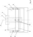
Figure 1 is a first diagrammatic side view of an oscillating table according to the invention; -
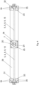
Figure 2 is a second diagrammatic side view of the oscillating table inFigure 1 ; -
Figure 3 is a perspective view of a component of the oscillating table of the invention; -
Figure 4 is a side view, partially sectioned at the ends, of a further component of the oscillating table of the invention. - The same reference numbers in the figures identify the same elements or components.
- The figures show an oscillating table, object of the present invention, comprising:
- a support fixed frame 1, integrally fixed to the ground or to supports, preferably made of metal, which are in turn fixed to the ground;
- an oscillating structure or
stand 2, called oscillating table stand, inserted in the support fixed frame 1 and adapted to accommodate aningot mold 3 provided with acrystallizer 4 defining a casting direction X; - at least one
actuator 14, adapted to transmit pulses with an alternating orientation, upwards and downwards, to theoscillating structure 2, so as to cause an oscillation motion thereof with respect to the support fixed frame 1; - elastic means, arranged transversely to the casting direction X and adapted to guide the oscillation motion of the
oscillating structure 2. - Said elastic means comprise, in all embodiments of the invention, two first
elastic bars 5, 5' and two secondelastic bars 6, 6', defining a respective axis, having two respective ends fixed indirectly to the support fixed frame 1, and having a respective central portion 7 constrained to theoscillating structure 2. - The two first
elastic bars 5, 5' are arranged parallel to each other, being positioned at a first side and at a second side of said support fixed frame 1, respectively, said first side and said second side being parallel to each other and equally spaced apart from said casting direction X. Also, the secondelastic bars 6, 6' are arranged parallel to each other, being respectively positioned at said first side and at said second side, below the firstelastic bars 5, 5' (Figure 2 ). - Advantageously, the first
elastic bars 5, 5' are inclined, in an adjustable manner, by a first acute angle with respect to a horizontal plane, while the secondelastic bars 6, 6' are inclined, in an adjustable manner, by a second acute angle, different from said first acute angle, with respect to said horizontal plane, whereby the two ideal intersection points between the axes of the first elastic bars and the corresponding axes of the underlying second elastic bars define an ideal oscillation axis Y about which theoscillating structure 2 can oscillate (Figure 1 ). A casting radius R is also shown inFigure 1 . - Preferably, both the first
elastic bars 5, 5' and the secondelastic bars 6, 6' are arranged symmetrically with respect to a plane containing the casting direction X (Figure 2 ). - In a first variant, the first acute angle of inclination of the first
elastic bars 5, 5' and the second acute angle of inclination of the secondelastic bars 6, 6' have the same sign with respect to the horizontal plane containing the ideal oscillation axis Y (Figure 1 ). - Instead, in a second variant (not shown), the first acute angle and the second acute angle are of opposite sign with respect to the horizontal plane containing the ideal oscillation axis Y.
- In an embodiment of the oscillating table of the invention, the
oscillating structure 2 is provided with a plurality of lockingdevices 20, onelocking device 20 for each of the firstelastic bars 5, 5' and the secondelastic bars 6, 6'. - Preferably, each locking
device 20 comprises, preferably consists of (Figure 3 ): - a
first part 21, proximal to theoscillating structure 2, on which a central portion 7 (not shown inFigure 3 ) of a respective firstelastic bar 5, 5' or secondelastic bar 6, 6' is initially inserted during the assembly step of the table; - and a
second part 22, distal from theoscillating structure 2 and superimposed on thefirst part 21 and the respective central portion 7 to lock the central portion 7 of the elastic bar and/or saidfirst part 21 in position, after having adjusted the inclination of the elastic bar. - In a first variant of the
locking device 20, thefirst part 21, e.g. in the form of a protruding pin, is fixed to theoscillating structure 2 so that said first part can rotate about its own axis Z. The end face of the pin, distal from theoscillating structure 2, is provided with agroove 23 in which the central portion 7 of the respectiveelastic bar second part 22 of the locking device, e.g., in the form of a fixing flange, is applied to thefirst part 21, locking in position both the central portion 7, and thus the elastic bar, and thefirst part 21 of the device. Thesecond part 22 can be fixed to thefirst part 21 of thelocking device 20 and to theoscillating structure 2 by means of a plurality of fixing means, such as screws, which cross thefirst part 21 completely. Alternatively, as shown inFigure 3 , thesecond part 22 can be fixed to thefirst part 21 by means of a plurality of first fixing means, such asscrews 24, while thefirst part 21 can be fixed to theoscillating structure 2 by means of a plurality of second fixing means, such as screws 25. Preferably, a fixingflange 26 is provided which constitutes a base of thefirst part 21, the latter being in the form of a pin protruding from said base. Thescrews 25, in this case, completely cross the fixingflange 26. In a second variant of thelocking device 20, thefirst part 21, e.g., in the form of a protruding pin, is integrally fixed to theoscillating structure 2. The end face of the pin, distal from theoscillating structure 2, is provided with agroove 23 in which the central portion 7 of the respectiveelastic bar groove 23 and said central portion 7 which allows the operator to adjust the angle of inclination of the elastic bar. Once the acute angle of inclination of the elastic bar has been adjusted, and the clearance has possibly been eliminated by inserting at least one shim, thesecond part 22 of the locking device, e.g., in the form of a fixing flange, is applied to thefirst part 21, locking in position the central portion 7, and thus the elastic bar. As shown inFigure 3 , thesecond part 22 can be fixed to thefirst part 21 by means of a plurality of first fixing means, such asscrews 24, while thefirst part 21 can be fixed to theoscillating structure 2 by means of a plurality of second fixing means, such as screws 25. Preferably, a fixingflange 26 is provided which constitutes a base of thefirst part 21, the latter being in the form of a pin protruding from said base. Thescrews 25, in this case, completely cross the fixingflange 26. - Advantageously, in all the embodiments of the invention, each first
elastic bar 5, 5' and each secondelastic bar 6, 6' are housed within a respective hollow housing, or longitudinal shell orbox 30, defining a longitudinal axis either coinciding with or parallel to the axis of the respective elastic bar contained therein. In other words, eachelastic bar hollow housing 30. Therefore, there are as manyhollow housings 30 as there areelastic bars - The two ends 31, 32 of each first and second elastic bar are fixed and advantageously pretensioned within corresponding ends 33, 34 of the respective
hollow housing 30. - The elastic bar within the respective
hollow housing 30 is previously pretensioned in the workshop according to known techniques, e.g., by locking the tie-rod in the central stretch and then tensioning the two ends one by one using torque wrenches to the desired values. - The two ends 33, 34 of each
hollow housing 30 are removably fixed to the support fixed frame 1, e.g., by means of a series ofscrew 35. - Therefore, the elastic bar is indirectly fixed to the support fixed frame 1.
- The central portion of the
hollow housing 30 has at least one through-hole 36, preferably only one through-hole 36, transverse to the longitudinal axis of the hollow housing, at which the central portion 7 of the respectiveelastic bar oscillating structure 2, e.g., in the manners described above. - Such a through-
hole 36 is, for example, suitable for being crossed by arespective fixing device 20, such as those described above. - Regarding the table oscillation actuation system, an embodiment provides a body 11 hinged to the support fixed frame 1, e.g., by one or two pins, and adapted to oscillate about said one or two pins by means of at least one
actuator 14, preferably a single actuator. Theoscillating structure 2 rests on said body 11, thus being able to oscillate together with the body 11. The body 11 can be hinged directly on the support fixed frame 1 or indirectly on one or twoprotrusions 27 of said support fixed frame 1, as shown inFigure 1 . - Preferably, the body 11 is provided with two
arms 12 arranged at said first side and said second side, respectively, of the support fixed frame 1, and theoscillating structure 2 rests on said twoarms 12. - In an embodiment of the table of the invention, both the support fixed frame 1 and the
oscillating structure 2, inserted therein, have four side walls, thus four sides, substantially perpendicular to the ground. In particular, the four side walls of the support fixed frame 1 have at least one large opening so that the side walls of theoscillating structure 2 are accessible. Therefore, thelocking devices 20 described above are accessible to the operator through these openings. - In a variant of the table, two third
elastic bars central portion 10 constrained to theoscillating structure 2. - These two third
elastic bars elastic bars 5, 5' and to the secondelastic bars 6, 6', and positioned at a third side of the support fixed frame 1, which is transverse to said first side and said second side. - The two third
elastic bars - The function of said two third
elastic bars - The body 11, on which the
oscillating structure 2 rests, can be hinged to the support fixed frame 1, either directly or indirectly, at a fourth side thereof, opposite said third side. - At least one fourth
elastic bar 13 can also be provided, preferably only one fourth elastic bar, having both ends fixed to the support fixed frame 1 and a central portion thereof constrained to theoscillating structure 2. - This fourth
elastic bar 13 is arranged parallel to the thirdelastic bars elastic bar 13 is also preferably arranged horizontally. - The function of said fourth
elastic bar 13 is again to contain the lateral skidding of the table during the oscillation. - Preferably, the fourth
elastic bar 13 can be arranged either above or below thearms 12 of the body 11, or simply either above or below the body 11, at one end of the secondelastic bars 6, 6'. - Preferably, the central portions of the two third
elastic bars elastic bar 13 can also be constrained to theoscillating structure 2 by means of arespective locking device 20, such as that described above. - The aforementioned hollow housing 30 (
Figure 4 ) can also be provided for the two thirdelastic bars elastic bar 13. - In this case, the third
elastic bars hollow housing 30 defining a longitudinal axis parallel to the axis of the respective third elastic bar contained therein. The two ends 31, 32 of each thirdelastic bar hollow housing 30, whereas the two ends 33, 34 of eachhollow housing 30 are removably fixed to the support fixed frame 1. The central part of eachhollow housing 30 also has at least one through-hole 36, preferably a single through-hole, transverse to the longitudinal axis of the hollow housing, at acentral portion 10 of the respective third elastic bar allowing to either constrain or release saidcentral portion 10 with respect to theoscillating structure 2. - Similarly, also the fourth
elastic bar 13 is housed within a correspondinghollow housing 30 defining a longitudinal axis parallel to the axis of the fourth elastic bar. The two ends 31, 32 of the fourthelastic bar 13 are fixed and pretensioned within corresponding ends 33, 34 of thehollow housing 30, while the two ends 33, 34 of thehollow housing 30 are removably fixed to the support fixed frame 1. The central part of thehollow housing 30 also has at least one through-hole 36, preferably a single through-hole, transverse to the longitudinal axis of the hollow housing, at the central portion of the fourthelastic bar 13 to allow either constraining or releasing said central portion to or from theoscillating structure 2. - An assembly method of an oscillating table according to the invention is described below, wherein it is provided that each first
elastic bar 5, 5' and each secondelastic bar 6, 6' are housed within a respectivehollow housing 30, the two ends 31, 32 of each firstelastic bar 5, 5' and each secondelastic bar 6, 6' being fixed and pretensioned within corresponding ends 33, 34 of the respectivehollow housing 30. Such a method comprises the following steps: - a) inserting the
oscillating structure 2 at least partially into the support fixed frame 1; - b) inserting the central portion 7 of each first
elastic bar 5, 5' and each secondelastic bar 6, 6' onto theoscillating structure 2, said central portion 7 being accessible thanks to the presence of the through-hole 36 of the central part of the respectivehollow housing 30; - c) adjusting the first acute angle of inclination of the first
elastic bars 5, 5' and the second acute angle of inclination of the secondelastic bars 6, 6'; - d) indirectly fixing the ends of the first
elastic bars 5, 5' and the ends of the secondelastic bars 6, 6' to the support fixed frame 1 by fixing the two ends 33, 34 of eachhollow housing 30 in a removable manner to the fixed frame 1; - e) fixing the central portion 7 of each first
elastic bar 5, 5' and each secondelastic bar 6, 6' to theoscillating structure 2, again by using the through-hole 36. - After step e), the insertion of the
ingot mold 3, equipped with thecrystallizer 4, into theoscillating structure 2, can be provided. - The steps (d) and (e) can be reversed.
- In step d), the ends 33, 34 of the
hollow housings 30 of the firstelastic bars 5, 5' and of the secondelastic bars 6, 6' can be fixed to the support fixed frame 1 with any reversible fixing means, i.e., adapted to allow said ends 33, 34 to be loosened, when necessary, from the support fixed frame 1 and fixed to said support fixed frame 1 again. - In a first variant of the assembly method, it is provided that
- in step b), the central portion 7 of each first
elastic bar 5, 5' and each secondelastic bar 6, 6' is fitted in afirst part 21, e.g., in the form of a protruding pin, of arespective fixing device 20, saidfirst part 21 being proximal and fixed to theoscillating structure 2 so as to rotate about its own axis transverse to theoscillating structure 2; - in step c) the first acute angle and the second acute angle are adjusted by rotating the respective
first part 21 about the axis thereof; - in step e) the fixing of the respective central portion 7 to the
oscillating structure 2 occurs by applying asecond part 22, e.g., in the form of a fixing flange, of thelocking device 20 onto thefirst part 21. - In step b), for example, the central portion 7 of each first
elastic bar 5, 5' and each secondelastic bar 6, 6' is fitted in agroove 23 of saidfirst part 21 of therespective locking device 20. - In particular, in step b) the central portion 7 of each first
elastic bar 5, 5' and each secondelastic bar 6, 6' is fitted in thefirst part 21 of the fixingdevice 20 thanks to the presence of the through-hole 36 provided in the central part of thehollow housing 30. The first acute angle and the second acute angle are adjusted by rotating the respectivefirst part 21 about its own axis, because the operator can rotate thefirst part 21 through said through-hole 36. The application of thesecond part 22 on thefirst part 21 to fix the respective central portion 7 to theoscillating structure 2 is also performed through the through-hole 36 of thehollow housing 30. Instead, in a second variant of the assembly method, it is provided that - in step b) the central portion 7 of each first
elastic bar 5, 5' and each secondelastic bar 6, 6' is inserted into agroove 23 of afirst part 21, e.g., in the form of a protruding pin, of arespective fixing device 20, saidfirst part 21 being proximal to and integrally fixed to theoscillating structure 2; - in step c) the first acute angle and the second acute angle are adjusted by fixing the respective central portion 7 within the corresponding
groove 23, e.g., by inserting at least one shim to eliminate the clearance between saidgroove 23 and the central portion 7; - in step e) the fixing of the respective central portion 7 to the
oscillating structure 2 occurs by applying asecond part 22, e.g., in the form of a fixing flange, of thelocking device 20 onto thefirst part 21. - In particular, in step b) the central portion 7 of each first
elastic bar 5, 5' and each secondelastic bar 6, 6' is inserted in thefirst part 21 of the fixingdevice 20 by virtue of the presence of the through-hole 36 provided in the central part of thehollow housing 30. The first acute angle and the second acute angle are adjusted by fixing the respective central portion 7 within the correspondinggroove 23, e.g., by inserting, using said through-hole 36, at least one shim to eliminate the clearance between saidgroove 23 and the central portion 7. The application of thesecond part 22 on thefirst part 21 to fix the respective central portion 7 to theoscillating structure 2 is also performed through the through-hole 36 of thehollow housing 30. - Preferably, the following is also provided:
- inserting a
central portion 10 of the two thirdelastic bars oscillating structure 2, arranging said third elastic bars parallel to each other and transverse to the firstelastic bars 5, 5' and the secondelastic bars 6, 6', at a third side of the support fixed frame 1 which is transverse to said first side and said second side; - fixing both ends of the third
elastic bars hollow housing 30 is also provided for theseelastic bars - fixing the
central portion 10 of each thirdelastic bar oscillating structure 2;
and optionally - inserting a central portion of at least one fourth
elastic bar 13 onto theoscillating structure 2, arranging said fourth elastic bar parallel to the thirdelastic bars - fixing both ends of said fourth
elastic bar 13 to the support fixed frame, either directly or indirectly if thehollow housing 30 is also provided for theelastic bar 13; - fixing the central portion of said fourth
elastic bar 13 to theoscillating structure 2. Advantageously, with the solution of the invention, if maintenance of the oscillating table is necessary, it is sufficient to release the central portion 7 of eachelastic bar oscillating structure 2 and remove the two ends 33, 34 of thehollow housing 30 containing the elastic bar from the support fixed frame 1 for possible replacement or other maintenance operation. - Then, after maintenance, the first acute angle of inclination of the first
elastic bars 5, 5' and the second acute angle of inclination of the secondelastic bars 6, 6' are adjusted again, and finally the ends 33, 34 of thehollow housings 30 of the firstelastic bars 5, 5' and theends hollow housings 30 of the secondelastic bars 6, 6' are fixed again to the support fixed frame 1, and the central portion 7 of each firstelastic bar 5, 5' and each secondelastic bar 6, 6' is fixed to theoscillating structure 2. - Therefore, the central portion 7 of the first and second elastic bars is maintained at a respective portion of the
oscillating structure 2, preferably at arespective locking device 20, only the inclination of saidelastic bars - Similarly, it is possible to proceed with the possible third
elastic bars elastic bar 13, although no angle of inclination with respect to the horizontal has to be adjusted for these elastic bars.
Claims (15)
- An oscillating table comprisinga support fixed frame (1), adapted to be fixed integrally to the ground or to supports fixed to the ground;- an oscillating structure (2), insertable into said fixed frame (1) and adapted to accommodate an ingot mold (3) provided with a crystallizer (4) defining a casting direction X;- at least one actuator (14), adapted to transmit pulses in an alternating direction, upwards and downwards, to the oscillating structure (2), so as to cause an oscillation motion thereof with respect to the fixed frame (1);- elastic means, arranged transversely to the casting direction X and adapted to guide said oscillation motion of the oscillating structure (2);wherein said elastic means comprise two first elastic bars (5, 5') and two second elastic bars (6, 6'), each defining a respective axis, having two respective ends fixed to the fixed frame (1), and having a respective central portion (7) constrained to the oscillating structure (2),wherein the first elastic bars (5, 5') are arranged parallel to each other, at a first side and at a second side of said fixed frame (1), respectively, said first side and said second side being parallel to each other and equally spaced apart from said casting direction X,wherein the second elastic bars (6, 6') are arranged parallel to each other, respectively at said first side and said second side, below the first elastic bars (5, 5'),wherein the first elastic bars (5, 5') are inclined by a first acute angle with respect to a horizontal plane,and wherein the second elastic bars (6, 6') are inclined by a second acute angle, different from said first acute angle, with respect to said horizontal plane, whereby two ideal intersection points between the axes of the first elastic bars and the corresponding axes of the underlying second elastic bars define an ideal oscillation axis (Y) about which the oscillating structure (2) can oscillate;wherein each first elastic bar (5, 5') and each second elastic bar (6, 6') are housed inside a respective hollow housing (30) defining a longitudinal axis parallel to the axis of the respective elastic bar contained therein;wherein the two ends (31, 32) of each first elastic bar (5, 5') and each second elastic bar (6, 6') are fixed and pretensioned inside corresponding ends (33, 34) of the respective hollow housing (30);wherein the two ends (33, 34) of each hollow housing (30) are removably fixed to the support fixed frame (1);and wherein a central part of each hollow housing (30) has at least one through-hole (36), transversal to the longitudinal axis of the hollow housing, at the respective central portion (7) to allow to either constraining or releasing said central portion (7) with respect to the oscillating structure (2).
- An oscillating table according to claim 1, wherein said first acute angle and said second acute angle are of the same sign or of opposite sign with respect to the horizontal plane containing said ideal oscillation axis (Y).
- An oscillating table according to claim 1 or 2, wherein the oscillating structure (2) is provided with a plurality of locking devices (20), one for each of the first elastic bars (5, 5') and second elastic bars (6, 6'), each locking device (20) having a first part (21), on which a respective central portion (7) is inserted, and a second part (22) overlapping the first part (21) and the respective central portion (7) to lock said central portion (7) and/or said first part (21) in position after an adjustment of the inclination of the respective first or second elastic bar.
- An oscillating table according to any one of the preceding claims, wherein both the first elastic bars (5, 5') and the second elastic bars (6, 6') are arranged symmetrically to a plane containing the casting direction X.
- An oscillating table according to any one of the preceding claims, wherein there is provided a body (11), hinged to said fixed frame (1); wherein the oscillating structure (2) is resting on said body (11); and wherein said at least one actuator (14) is adapted to cause said body (11) to oscillate; preferably
wherein the body (11) is provided with two arms (12), a first arm being arranged at said first side and a second arm being arranged at said second side; and wherein the oscillating structure (2) is resting on said two arms (12). - An oscillating table according to any one of the preceding claims, wherein there are provided two third elastic bars (8, 9), having both ends fixed to the fixed frame (1) and a central portion (10) constrained to the oscillating structure (2), said two third elastic bars (8, 9) being arranged parallel to each other and transverse to the first elastic bars (5, 5') and the second elastic bars (6, 6'), and positioned at a third side of the fixed frame (1), which is transverse to said first side and said second side; preferably
wherein there is provided a body (11), hinged to said fixed frame (1) at a fourth side thereof opposite to said third side; wherein the oscillating structure (2) is resting on said body (11); and wherein said at least one actuator (14) is adapted to cause said body (11) to oscillate. - An oscillating table according to claim 6, wherein there is provided at least one fourth elastic bar (13), preferably only one fourth elastic bar (13), having both ends fixed to the fixed frame (1) and a central portion thereof constrained to the oscillating structure (2), said at least one fourth elastic bar (13) being arranged parallel to the third elastic bars (8, 9) at a fourth side of the fixed frame (1), opposite to said third side; preferably
wherein said at least one fourth elastic bar (13) is arranged above or below the arms (12) of the body (11), preferably at the second elastic bars (6, 6'). - An oscillating table according to claim 6 or 7, wherein the third elastic bars (8, 9) are also housed within a respective hollow housing (30) defining a longitudinal axis parallel to the axis of the respective third elastic bar contained therein;wherein the two ends (31, 32) of each third elastic bar (8, 9) are fixed and pretensioned within corresponding ends (33, 34) of the respective hollow housing (30);wherein the two ends (33, 34) of each hollow housing (30) are removably fixed to the support fixed frame (1);and wherein a central part of each hollow housing (30) has at least one through-hole (36), transverse to the longitudinal axis of the hollow housing, at the central portion (10) of the respective third elastic bar to allow either constraining or releasing said central portion (10) to or from the oscillating structure (2).
- An oscillating table according to claim 7, wherein said at least one fourth elastic bar (13) is housed within a hollow housing (30) defining a longitudinal axis parallel to the axis of the fourth elastic bar;wherein the two ends (31, 32) of said at least one fourth elastic bar (13) are fixed and pretensioned within corresponding ends (33, 34) of the hollow housing (30); wherein the two ends (33, 34) of the hollow housing (30) are removably fixed to the support fixed frame (1);and wherein a central part of the hollow housing (30) has at least one through-hole (36), transverse to the longitudinal axis of the hollow housing, at the central portion of the fourth elastic bar (13) to allow either constraining or releasing said central portion to or from the oscillating structure (2).
- An oscillating table according to any one of the preceding claims, wherein the two ends (33, 34) of each hollow housing (30) of the first and second elastic bars are removably fixed to the support fixed frame (1) at predefined areas provided on the support fixed frame (1), preferably at predetermined holes corresponding to different inclinations of the first and second elastic bars.
- An method of assembling an oscillating table according to any one of the preceding claims, wherein it is provided that each first elastic bar (5, 5') and each second elastic bar (6, 6') are housed within a respective hollow housing (30), the two ends (31, 32) of each first elastic bar (5, 5') and each second elastic bar (6, 6') being fixed and pretensioned within corresponding ends (33, 34) of the respective hollow housing (30);
the method comprising the following steps:a) inserting the oscillating structure (2) at least partially into the fixed frame (1);b) inserting the central portion (7) of each first elastic bar (5, 5') and each second elastic bar (6, 6') onto the oscillating structure (2) by means of the through-hole (36) of the central part of the respective hollow housing (30);c) adjusting the first acute angle of inclination of the first elastic bars (5, 5') and the second acute angle of inclination of the second elastic bars (6, 6');d) removably fixing the two ends (33, 34) of each hollow housing (30) to the fixed frame (1);e) fixing the central portion (7) of each first elastic bar (5, 5') and each second elastic bar (6, 6') to the oscillating structure (2). - A method according to claim 11, wherein after step e) there is provided the insertion of the ingot mold (3), provided with the crystallizer (4), into the oscillating structure (2).
- A method according to claim 11, wherein steps d) and e) can be inverted.
- A method according to any one of the claims from 11 to 13, wherein, in step b) the central portion (7) of each first elastic bar (5, 5') and each second elastic bar (6, 6') is inserted onto the oscillating structure (2) at a respective fixing device (20) provided on said oscillating structure (2); preferably
wherein- in step b) the central portion (7) of each first elastic bar (5, 5') and each second elastic bar (6, 6') is fitted in a first part (21) of a respective fixing device (20), said first part (21) being proximal and fixed to the oscillating structure (2) so as to rotate about an axis thereof transverse to the oscillating structure (2);- in step c) the first acute angle and the second acute angle are adjusted by rotating the respective first part (21) about the axis thereof;- in step e) the fixing of the respective central portion (7) to the oscillating structure (2) occurs by applying a second part (22) of the locking device (20) onto the first part (21);or wherein- in step b) the central portion (7) of each first elastic bar (5, 5') and each second elastic bar (6, 6') is inserted into a groove (23) of a first part (21) of a respective fixing device (20), said first part (21) being proximal and fixed integrally to the oscillating structure (2);- in step c) the first acute angle and the second acute angle are adjusted by fixing the respective central portion (7) inside the corresponding groove (23), by eliminating the yoke between said central portion (7) and said groove (23);- in step e) the fixing of the respective central portion (7) to the oscillating structure (2) occurs by applying a second part (22) of the locking device (20) onto the first part (21). - A method according to any one of the claims from 11 to 13, wherein there is further provided- inserting a central portion (10) of two third elastic bars (8, 9) onto the oscillating structure (2), arranging them parallel to each other and transverse to the first elastic bars (5, 5') and to the second elastic bars (6, 6'), at a third side of the fixed frame (1) which is transverse to said first side and said second side;- fixing both ends of said third elastic bars (8, 9) to the fixed frame (1);- fixing the central portion (10) of each third elastic bar (8, 9) to the oscillating structure (2);and, preferably, wherein there is further provided- inserting a central portion of at least one fourth elastic bar (13) onto the oscillating structure (2), arranging it parallel to the third elastic bars (8, 9) at a fourth side of the fixed frame (1), opposite to said third side;- fixing both ends of said fourth elastic bar (13) to the fixed frame (1);- fixing the central portion of said fourth elastic bar (13) to the oscillating structure (2).
Applications Claiming Priority (2)
| Application Number | Priority Date | Filing Date | Title |
|---|---|---|---|
| IT102020000022390A IT202000022390A1 (en) | 2020-09-23 | 2020-09-23 | OSCILLATING BENCH AND RELATED ASSEMBLY METHOD |
| PCT/IB2021/058667 WO2022064403A1 (en) | 2020-09-23 | 2021-09-23 | Oscillating table and assembly method thereof |
Publications (3)
| Publication Number | Publication Date |
|---|---|
| EP4217134A1 EP4217134A1 (en) | 2023-08-02 |
| EP4217134B1 true EP4217134B1 (en) | 2024-08-21 |
| EP4217134C0 EP4217134C0 (en) | 2024-08-21 |
Family
ID=73793601
Family Applications (1)
| Application Number | Title | Priority Date | Filing Date |
|---|---|---|---|
| EP21790997.7A Active EP4217134B1 (en) | 2020-09-23 | 2021-09-23 | Oscillating table and assembly method thereof |
Country Status (5)
| Country | Link |
|---|---|
| US (1) | US12036602B2 (en) |
| EP (1) | EP4217134B1 (en) |
| CN (1) | CN116234649A (en) |
| IT (1) | IT202000022390A1 (en) |
| WO (1) | WO2022064403A1 (en) |
Family Cites Families (7)
| Publication number | Priority date | Publication date | Assignee | Title |
|---|---|---|---|---|
| US5219029A (en) * | 1992-03-09 | 1993-06-15 | Gunther Behrends | Oscillator for continuous casting mold |
| DE19817701C2 (en) * | 1998-04-21 | 2000-09-28 | Sms Demag Ag | Lifting table with oscillation drive for a continuous caster |
| ITMI20060334A1 (en) * | 2006-02-24 | 2007-08-25 | Danieli Off Mecc | SWINGING BENCH |
| CN101342582B (en) * | 2008-08-28 | 2010-11-24 | 中冶连铸技术工程股份有限公司 | Hydraulic vibration device for square, round and special-shaped blanks |
| CN101648259B (en) * | 2009-08-26 | 2011-06-29 | 中冶连铸技术工程股份有限公司 | A vibration device for continuous casting machine crystallizer |
| CN202224616U (en) * | 2011-08-16 | 2012-05-23 | 中冶连铸技术工程股份有限公司 | Flexible vibration device for continuous casting |
| JP6788513B2 (en) * | 2017-01-24 | 2020-11-25 | 株式会社神戸製鋼所 | Mold vibrating device for continuous casting equipment |
-
2020
- 2020-09-23 IT IT102020000022390A patent/IT202000022390A1/en unknown
-
2021
- 2021-09-23 CN CN202180064662.3A patent/CN116234649A/en active Pending
- 2021-09-23 US US18/246,017 patent/US12036602B2/en active Active
- 2021-09-23 WO PCT/IB2021/058667 patent/WO2022064403A1/en not_active Ceased
- 2021-09-23 EP EP21790997.7A patent/EP4217134B1/en active Active
Also Published As
| Publication number | Publication date |
|---|---|
| US12036602B2 (en) | 2024-07-16 |
| CN116234649A (en) | 2023-06-06 |
| EP4217134A1 (en) | 2023-08-02 |
| WO2022064403A1 (en) | 2022-03-31 |
| IT202000022390A1 (en) | 2022-03-23 |
| EP4217134C0 (en) | 2024-08-21 |
| US20230372997A1 (en) | 2023-11-23 |
Similar Documents
| Publication | Publication Date | Title |
|---|---|---|
| EP0468607B2 (en) | Fluid cooled mould for continuous casting of metals | |
| WO1997013603A9 (en) | METHOD OF MANUFACTURING OPTICAL SURFACES AND CLEAN MACHINE MACHINE FOR CARRYING OUT SAID METHOD | |
| US5783231A (en) | Mold closing device without cross-beam | |
| US12036602B2 (en) | Oscillating table and assembly method thereof | |
| KR20250036939A (en) | Embossing System with Embossing Cassette | |
| EP1996351B1 (en) | Casting apparatus with an oscillating table | |
| EP0309394B1 (en) | Rolling mill stand or continuous-casting stand | |
| US6145575A (en) | Continuous casting machine | |
| US3987657A (en) | Roll setting device for rolling mills for metal bars or the like | |
| EP1763414B1 (en) | Device for supporting an oscillating a continuous casting mold for continuously casting molten metals, particularly molten metal materials, and method for assembling, disassembling and maintaining the device | |
| DE4444941C3 (en) | continuous casting | |
| EP0222732B1 (en) | Strand guide | |
| EP0010728B1 (en) | Continuous-casting assembly with an oscillating mould | |
| US4706733A (en) | Continuous casting machine | |
| EP0074247A1 (en) | Multi-point straightening bow type continuous-casting machine having a low machine height | |
| DE7014162U (en) | ROLLED FRAMEWORK, IN PARTICULAR FOR THE DEFORMING OF A CAST STRAND LEAVING DIRECTLY FROM A CONTINUOUS CASTING PLANT. | |
| AT408625B (en) | CASTING | |
| US3951323A (en) | Removable upper guide roll unit in a continuous metal casting installation | |
| US4228844A (en) | Strand guiding stand for continuous casting apparatus | |
| JP2987825B2 (en) | Four-roll mill and roll changing method | |
| US12030106B2 (en) | Turret roll formers, forming roller cassettes and related articles and methods | |
| JPS6038231B2 (en) | Slab support and guide device for continuous casting equipment | |
| DE4447941B4 (en) | A continuously casting chill mould for rectangular slabs - which reduces construction costs, maintenance and mould change times, without sacrificing rigidity | |
| EP4647191A1 (en) | Clamping device for a core package and method for casting | |
| EP0827792B1 (en) | Continuous-casting mold with oscillation means |
Legal Events
| Date | Code | Title | Description |
|---|---|---|---|
| STAA | Information on the status of an ep patent application or granted ep patent |
Free format text: STATUS: UNKNOWN |
|
| STAA | Information on the status of an ep patent application or granted ep patent |
Free format text: STATUS: THE INTERNATIONAL PUBLICATION HAS BEEN MADE |
|
| PUAI | Public reference made under article 153(3) epc to a published international application that has entered the european phase |
Free format text: ORIGINAL CODE: 0009012 |
|
| STAA | Information on the status of an ep patent application or granted ep patent |
Free format text: STATUS: REQUEST FOR EXAMINATION WAS MADE |
|
| 17P | Request for examination filed |
Effective date: 20230323 |
|
| AK | Designated contracting states |
Kind code of ref document: A1 Designated state(s): AL AT BE BG CH CY CZ DE DK EE ES FI FR GB GR HR HU IE IS IT LI LT LU LV MC MK MT NL NO PL PT RO RS SE SI SK SM TR |
|
| P01 | Opt-out of the competence of the unified patent court (upc) registered |
Effective date: 20230803 |
|
| DAV | Request for validation of the european patent (deleted) | ||
| DAX | Request for extension of the european patent (deleted) | ||
| GRAP | Despatch of communication of intention to grant a patent |
Free format text: ORIGINAL CODE: EPIDOSNIGR1 |
|
| STAA | Information on the status of an ep patent application or granted ep patent |
Free format text: STATUS: GRANT OF PATENT IS INTENDED |
|
| INTG | Intention to grant announced |
Effective date: 20240312 |
|
| GRAS | Grant fee paid |
Free format text: ORIGINAL CODE: EPIDOSNIGR3 |
|
| GRAA | (expected) grant |
Free format text: ORIGINAL CODE: 0009210 |
|
| STAA | Information on the status of an ep patent application or granted ep patent |
Free format text: STATUS: THE PATENT HAS BEEN GRANTED |
|
| AK | Designated contracting states |
Kind code of ref document: B1 Designated state(s): AL AT BE BG CH CY CZ DE DK EE ES FI FR GB GR HR HU IE IS IT LI LT LU LV MC MK MT NL NO PL PT RO RS SE SI SK SM TR |
|
| REG | Reference to a national code |
Ref country code: GB Ref legal event code: FG4D |
|
| REG | Reference to a national code |
Ref country code: CH Ref legal event code: EP |
|
| REG | Reference to a national code |
Ref country code: DE Ref legal event code: R096 Ref document number: 602021017642 Country of ref document: DE |
|
| REG | Reference to a national code |
Ref country code: IE Ref legal event code: FG4D |
|
| U01 | Request for unitary effect filed |
Effective date: 20240916 |
|
| U07 | Unitary effect registered |
Designated state(s): AT BE BG DE DK EE FI FR IT LT LU LV MT NL PT RO SE SI Effective date: 20241004 |
|
| P04 | Withdrawal of opt-out of the competence of the unified patent court (upc) registered |
Free format text: CASE NUMBER: APP_54061/2024 Effective date: 20240930 |
|
| U20 | Renewal fee for the european patent with unitary effect paid |
Year of fee payment: 4 Effective date: 20241028 |
|
| P05 | Withdrawal of opt-out of the competence of the unified patent court (upc) changed |
Free format text: CASE NUMBER: APP_54061/2024 Effective date: 20241004 |
|
| PG25 | Lapsed in a contracting state [announced via postgrant information from national office to epo] |
Ref country code: NO Free format text: LAPSE BECAUSE OF FAILURE TO SUBMIT A TRANSLATION OF THE DESCRIPTION OR TO PAY THE FEE WITHIN THE PRESCRIBED TIME-LIMIT Effective date: 20241121 |
|
| PG25 | Lapsed in a contracting state [announced via postgrant information from national office to epo] |
Ref country code: GR Free format text: LAPSE BECAUSE OF FAILURE TO SUBMIT A TRANSLATION OF THE DESCRIPTION OR TO PAY THE FEE WITHIN THE PRESCRIBED TIME-LIMIT Effective date: 20241122 Ref country code: PL Free format text: LAPSE BECAUSE OF FAILURE TO SUBMIT A TRANSLATION OF THE DESCRIPTION OR TO PAY THE FEE WITHIN THE PRESCRIBED TIME-LIMIT Effective date: 20240821 |
|
| PG25 | Lapsed in a contracting state [announced via postgrant information from national office to epo] |
Ref country code: IS Free format text: LAPSE BECAUSE OF FAILURE TO SUBMIT A TRANSLATION OF THE DESCRIPTION OR TO PAY THE FEE WITHIN THE PRESCRIBED TIME-LIMIT Effective date: 20241221 |
|
| PG25 | Lapsed in a contracting state [announced via postgrant information from national office to epo] |
Ref country code: HR Free format text: LAPSE BECAUSE OF FAILURE TO SUBMIT A TRANSLATION OF THE DESCRIPTION OR TO PAY THE FEE WITHIN THE PRESCRIBED TIME-LIMIT Effective date: 20240821 |
|
| PG25 | Lapsed in a contracting state [announced via postgrant information from national office to epo] |
Ref country code: RS Free format text: LAPSE BECAUSE OF FAILURE TO SUBMIT A TRANSLATION OF THE DESCRIPTION OR TO PAY THE FEE WITHIN THE PRESCRIBED TIME-LIMIT Effective date: 20241121 Ref country code: ES Free format text: LAPSE BECAUSE OF FAILURE TO SUBMIT A TRANSLATION OF THE DESCRIPTION OR TO PAY THE FEE WITHIN THE PRESCRIBED TIME-LIMIT Effective date: 20240821 |
|
| PG25 | Lapsed in a contracting state [announced via postgrant information from national office to epo] |
Ref country code: RS Free format text: LAPSE BECAUSE OF FAILURE TO SUBMIT A TRANSLATION OF THE DESCRIPTION OR TO PAY THE FEE WITHIN THE PRESCRIBED TIME-LIMIT Effective date: 20241121 Ref country code: PL Free format text: LAPSE BECAUSE OF FAILURE TO SUBMIT A TRANSLATION OF THE DESCRIPTION OR TO PAY THE FEE WITHIN THE PRESCRIBED TIME-LIMIT Effective date: 20240821 Ref country code: NO Free format text: LAPSE BECAUSE OF FAILURE TO SUBMIT A TRANSLATION OF THE DESCRIPTION OR TO PAY THE FEE WITHIN THE PRESCRIBED TIME-LIMIT Effective date: 20241121 Ref country code: IS Free format text: LAPSE BECAUSE OF FAILURE TO SUBMIT A TRANSLATION OF THE DESCRIPTION OR TO PAY THE FEE WITHIN THE PRESCRIBED TIME-LIMIT Effective date: 20241221 Ref country code: HR Free format text: LAPSE BECAUSE OF FAILURE TO SUBMIT A TRANSLATION OF THE DESCRIPTION OR TO PAY THE FEE WITHIN THE PRESCRIBED TIME-LIMIT Effective date: 20240821 Ref country code: GR Free format text: LAPSE BECAUSE OF FAILURE TO SUBMIT A TRANSLATION OF THE DESCRIPTION OR TO PAY THE FEE WITHIN THE PRESCRIBED TIME-LIMIT Effective date: 20241122 Ref country code: ES Free format text: LAPSE BECAUSE OF FAILURE TO SUBMIT A TRANSLATION OF THE DESCRIPTION OR TO PAY THE FEE WITHIN THE PRESCRIBED TIME-LIMIT Effective date: 20240821 |
|
| PG25 | Lapsed in a contracting state [announced via postgrant information from national office to epo] |
Ref country code: SM Free format text: LAPSE BECAUSE OF FAILURE TO SUBMIT A TRANSLATION OF THE DESCRIPTION OR TO PAY THE FEE WITHIN THE PRESCRIBED TIME-LIMIT Effective date: 20240821 |
|
| PG25 | Lapsed in a contracting state [announced via postgrant information from national office to epo] |
Ref country code: CZ Free format text: LAPSE BECAUSE OF FAILURE TO SUBMIT A TRANSLATION OF THE DESCRIPTION OR TO PAY THE FEE WITHIN THE PRESCRIBED TIME-LIMIT Effective date: 20240821 |
|
| PG25 | Lapsed in a contracting state [announced via postgrant information from national office to epo] |
Ref country code: SK Free format text: LAPSE BECAUSE OF FAILURE TO SUBMIT A TRANSLATION OF THE DESCRIPTION OR TO PAY THE FEE WITHIN THE PRESCRIBED TIME-LIMIT Effective date: 20240821 |
|
| REG | Reference to a national code |
Ref country code: CH Ref legal event code: PL |
|
| PLBE | No opposition filed within time limit |
Free format text: ORIGINAL CODE: 0009261 |
|
| STAA | Information on the status of an ep patent application or granted ep patent |
Free format text: STATUS: NO OPPOSITION FILED WITHIN TIME LIMIT |
|
| PG25 | Lapsed in a contracting state [announced via postgrant information from national office to epo] |
Ref country code: MC Free format text: LAPSE BECAUSE OF FAILURE TO SUBMIT A TRANSLATION OF THE DESCRIPTION OR TO PAY THE FEE WITHIN THE PRESCRIBED TIME-LIMIT Effective date: 20240821 |
|
| PG25 | Lapsed in a contracting state [announced via postgrant information from national office to epo] |
Ref country code: CH Free format text: LAPSE BECAUSE OF NON-PAYMENT OF DUE FEES Effective date: 20240930 |
|
| PG25 | Lapsed in a contracting state [announced via postgrant information from national office to epo] |
Ref country code: IE Free format text: LAPSE BECAUSE OF NON-PAYMENT OF DUE FEES Effective date: 20240923 |
|
| 26N | No opposition filed |
Effective date: 20250522 |
|
| PGFP | Annual fee paid to national office [announced via postgrant information from national office to epo] |
Ref country code: TR Payment date: 20250908 Year of fee payment: 5 |
|
| U20 | Renewal fee for the european patent with unitary effect paid |
Year of fee payment: 5 Effective date: 20250929 |
|
| PG25 | Lapsed in a contracting state [announced via postgrant information from national office to epo] |
Ref country code: CY Free format text: LAPSE BECAUSE OF FAILURE TO SUBMIT A TRANSLATION OF THE DESCRIPTION OR TO PAY THE FEE WITHIN THE PRESCRIBED TIME-LIMIT; INVALID AB INITIO Effective date: 20210923 |
|
| PG25 | Lapsed in a contracting state [announced via postgrant information from national office to epo] |
Ref country code: HU Free format text: LAPSE BECAUSE OF FAILURE TO SUBMIT A TRANSLATION OF THE DESCRIPTION OR TO PAY THE FEE WITHIN THE PRESCRIBED TIME-LIMIT; INVALID AB INITIO Effective date: 20210923 |