EP4216390A2 - Medium-to-high voltage power system for a transport refrigeration unit - Google Patents
Medium-to-high voltage power system for a transport refrigeration unit Download PDFInfo
- Publication number
- EP4216390A2 EP4216390A2 EP23150312.9A EP23150312A EP4216390A2 EP 4216390 A2 EP4216390 A2 EP 4216390A2 EP 23150312 A EP23150312 A EP 23150312A EP 4216390 A2 EP4216390 A2 EP 4216390A2
- Authority
- EP
- European Patent Office
- Prior art keywords
- bus
- converter
- coupled
- voltage
- evaporator
- Prior art date
- Legal status (The legal status is an assumption and is not a legal conclusion. Google has not performed a legal analysis and makes no representation as to the accuracy of the status listed.)
- Pending
Links
Images





Classifications
-
- B—PERFORMING OPERATIONS; TRANSPORTING
- B60—VEHICLES IN GENERAL
- B60H—ARRANGEMENTS OF HEATING, COOLING, VENTILATING OR OTHER AIR-TREATING DEVICES SPECIALLY ADAPTED FOR PASSENGER OR GOODS SPACES OF VEHICLES
- B60H1/00—Heating, cooling or ventilating devices
- B60H1/32—Cooling devices
- B60H1/3204—Cooling devices using compression
- B60H1/3228—Cooling devices using compression characterised by refrigerant circuit configurations
-
- F—MECHANICAL ENGINEERING; LIGHTING; HEATING; WEAPONS; BLASTING
- F25—REFRIGERATION OR COOLING; COMBINED HEATING AND REFRIGERATION SYSTEMS; HEAT PUMP SYSTEMS; MANUFACTURE OR STORAGE OF ICE; LIQUEFACTION SOLIDIFICATION OF GASES
- F25B—REFRIGERATION MACHINES, PLANTS OR SYSTEMS; COMBINED HEATING AND REFRIGERATION SYSTEMS; HEAT PUMP SYSTEMS
- F25B1/00—Compression machines, plants or systems with non-reversible cycle
-
- B—PERFORMING OPERATIONS; TRANSPORTING
- B60—VEHICLES IN GENERAL
- B60H—ARRANGEMENTS OF HEATING, COOLING, VENTILATING OR OTHER AIR-TREATING DEVICES SPECIALLY ADAPTED FOR PASSENGER OR GOODS SPACES OF VEHICLES
- B60H1/00—Heating, cooling or ventilating devices
- B60H1/00421—Driving arrangements for parts of a vehicle air-conditioning
- B60H1/00428—Driving arrangements for parts of a vehicle air-conditioning electric
-
- B—PERFORMING OPERATIONS; TRANSPORTING
- B60—VEHICLES IN GENERAL
- B60H—ARRANGEMENTS OF HEATING, COOLING, VENTILATING OR OTHER AIR-TREATING DEVICES SPECIALLY ADAPTED FOR PASSENGER OR GOODS SPACES OF VEHICLES
- B60H1/00—Heating, cooling or ventilating devices
- B60H1/32—Cooling devices
- B60H1/3202—Cooling devices using evaporation, i.e. not including a compressor, e.g. involving fuel or water evaporation
-
- B—PERFORMING OPERATIONS; TRANSPORTING
- B60—VEHICLES IN GENERAL
- B60H—ARRANGEMENTS OF HEATING, COOLING, VENTILATING OR OTHER AIR-TREATING DEVICES SPECIALLY ADAPTED FOR PASSENGER OR GOODS SPACES OF VEHICLES
- B60H1/00—Heating, cooling or ventilating devices
- B60H1/32—Cooling devices
- B60H1/3204—Cooling devices using compression
- B60H1/3232—Cooling devices using compression particularly adapted for load transporting vehicles
-
- H—ELECTRICITY
- H02—GENERATION; CONVERSION OR DISTRIBUTION OF ELECTRIC POWER
- H02J—ELECTRIC POWER NETWORKS; CIRCUIT ARRANGEMENTS OR SYSTEMS FOR SUPPLYING OR DISTRIBUTING ELECTRIC POWER; SYSTEMS FOR STORING ELECTRIC ENERGY
- H02J1/00—Circuit arrangements for DC mains or DC distribution networks
-
- H—ELECTRICITY
- H02—GENERATION; CONVERSION OR DISTRIBUTION OF ELECTRIC POWER
- H02J—ELECTRIC POWER NETWORKS; CIRCUIT ARRANGEMENTS OR SYSTEMS FOR SUPPLYING OR DISTRIBUTING ELECTRIC POWER; SYSTEMS FOR STORING ELECTRIC ENERGY
- H02J1/00—Circuit arrangements for DC mains or DC distribution networks
- H02J1/08—Three-wire DC power distribution systems; Systems having more than three wires
- H02J1/082—DC supplies with two or more different DC voltage levels
-
- H—ELECTRICITY
- H02—GENERATION; CONVERSION OR DISTRIBUTION OF ELECTRIC POWER
- H02J—ELECTRIC POWER NETWORKS; CIRCUIT ARRANGEMENTS OR SYSTEMS FOR SUPPLYING OR DISTRIBUTING ELECTRIC POWER; SYSTEMS FOR STORING ELECTRIC ENERGY
- H02J1/00—Circuit arrangements for DC mains or DC distribution networks
- H02J1/10—Parallel operation of DC sources
- H02J1/102—Parallel operation of DC sources being switching converters
-
- H—ELECTRICITY
- H02—GENERATION; CONVERSION OR DISTRIBUTION OF ELECTRIC POWER
- H02J—ELECTRIC POWER NETWORKS; CIRCUIT ARRANGEMENTS OR SYSTEMS FOR SUPPLYING OR DISTRIBUTING ELECTRIC POWER; SYSTEMS FOR STORING ELECTRIC ENERGY
- H02J7/00—Circuit arrangements for charging or discharging batteries or for supplying loads from batteries
- H02J7/855—Circuit arrangements for charging or discharging batteries or for supplying loads from batteries with circuits adapted for supplying loads from the battery
-
- H—ELECTRICITY
- H02—GENERATION; CONVERSION OR DISTRIBUTION OF ELECTRIC POWER
- H02M—APPARATUS FOR CONVERSION BETWEEN AC AND AC, BETWEEN AC AND DC, OR BETWEEN DC AND DC, AND FOR USE WITH MAINS OR SIMILAR POWER SUPPLY SYSTEMS; CONVERSION OF DC OR AC INPUT POWER INTO SURGE OUTPUT POWER; CONTROL OR REGULATION THEREOF
- H02M3/00—Conversion of DC power input into DC power output
-
- H—ELECTRICITY
- H02—GENERATION; CONVERSION OR DISTRIBUTION OF ELECTRIC POWER
- H02M—APPARATUS FOR CONVERSION BETWEEN AC AND AC, BETWEEN AC AND DC, OR BETWEEN DC AND DC, AND FOR USE WITH MAINS OR SIMILAR POWER SUPPLY SYSTEMS; CONVERSION OF DC OR AC INPUT POWER INTO SURGE OUTPUT POWER; CONTROL OR REGULATION THEREOF
- H02M7/00—Conversion of AC power input into DC power output; Conversion of DC power input into AC power output
- H02M7/02—Conversion of AC power input into DC power output without possibility of reversal
-
- H—ELECTRICITY
- H02—GENERATION; CONVERSION OR DISTRIBUTION OF ELECTRIC POWER
- H02J—ELECTRIC POWER NETWORKS; CIRCUIT ARRANGEMENTS OR SYSTEMS FOR SUPPLYING OR DISTRIBUTING ELECTRIC POWER; SYSTEMS FOR STORING ELECTRIC ENERGY
- H02J2207/00—Details of circuit arrangements for charging or discharging batteries or supplying loads from batteries
- H02J2207/20—Charging or discharging characterised by the power electronics converter
Definitions
- the present invention relates to transport refrigeration units, and more specifically, to medium-to-high voltage power systems for a transport refrigeration unit (TRU).
- TRU transport refrigeration unit
- Transport refrigeration units are used to cool cargo in a trailer or cargo container.
- Existing transport refrigeration units employ an engine and a generator to produce electrical power (e.g., AC power) to drive the compressor and fans (e.g., evaporator fans, condenser fans).
- electrical power e.g., AC power
- fans e.g., evaporator fans, condenser fans.
- Existing sources of AC power produce unregulated AC power that can vary in voltage and frequency. There may be a need for an all-electric solution for providing AC and DC power to the various loads for transport refrigeration units.
- a high-voltage system of a transport refrigeration unit includes a high-voltage direct current (HVDC) source; and a first converter coupling the HVDC source to a distribution bus, wherein the distribution bus is coupled to a compressor, at least one condenser (e.g. at least one condenser fan), and an at least one evaporator (e.g. at least one evaporator fan).
- HVDC high-voltage direct current
- evaporator e.g. at least one evaporator fan
- the distribution bus may be coupled to a compressor bus coupled to the compressor, a condenser bus coupled to the at least one condenser (e.g. at least one condenser fan), and an evaporator bus coupled to the at least one evaporator (e.g. at least one evaporator fan).
- a compressor bus coupled to the compressor
- a condenser bus coupled to the at least one condenser (e.g. at least one condenser fan)
- an evaporator bus coupled to the at least one evaporator (e.g. at least one evaporator fan).
- the first converter may be a DC-DC buck converter configured to step down voltage from the HVDC source, and optionally the distribution bus is a low voltage DC bus.
- the compressor bus may comprise a DC motor that is mechanically coupled to an open drive compressor, wherein the evaporator bus and the condenser bus are coupled to at least one DC-DC buck converter that is used to convert voltage from the distribution bus for the at least one evaporator (e.g. at least one evaporator fan) and the at least one condenser (e.g. at least one condenser fan).
- the at least one evaporator e.g. at least one evaporator fan
- the at least one condenser e.g. at least one condenser fan
- the system comprises: a compressor bus that comprises a DC motor that is mechanically coupled to an open drive compressor, an evaporator bus that comprises at least one first DC-DC buck converter to convert voltage from the distribution bus for the at least one evaporator (e.g. at least one evaporator fan), a condenser bus that comprises at least one second DC-DC buck converter to convert voltage from the distribution bus for the at least one condenser (e.g. at least one condenser fan), wherein the at least one first DC-DC buck converter and the at least one second DC-DC converter are different DC-DC converters.
- a compressor bus that comprises a DC motor that is mechanically coupled to an open drive compressor
- an evaporator bus that comprises at least one first DC-DC buck converter to convert voltage from the distribution bus for the at least one evaporator (e.g. at least one evaporator fan)
- a condenser bus that comprises at least one second DC-DC buck converter to convert voltage from the distribution bus for
- the system comprises: a compressor bus that comprises a DC motor that is mechanically coupled to an open drive compressor, an evaporator bus that comprises a DC-DC boost converter coupled to a DC-AC converter to convert voltage from the distribution bus for the at least one evaporator (e.g. at least one evaporator fan), a condenser bus that comprises a DC-DC boost converter coupled to a DC-AC converter to convert voltage from the distribution bus for the at least one condenser (e.g. at least one condenser fan).
- a compressor bus that comprises a DC motor that is mechanically coupled to an open drive compressor
- an evaporator bus that comprises a DC-DC boost converter coupled to a DC-AC converter to convert voltage from the distribution bus for the at least one evaporator (e.g. at least one evaporator fan)
- a condenser bus that comprises a DC-DC boost converter coupled to a DC-AC converter to convert voltage from the distribution bus for the at least one condenser (e.
- the system comprises: a compressor bus that comprises a DC-DC boost converter coupled to a DC-AC converter for the compressor, an evaporator bus and a condenser bus that are coupled to at least one DC-DC buck converter that is used to convert voltage from the distribution bus for the at least one evaporator (e.g. at least one evaporator fan) and the at least one condenser (e.g. at least one condenser fan).
- a compressor bus that comprises a DC-DC boost converter coupled to a DC-AC converter for the compressor, an evaporator bus and a condenser bus that are coupled to at least one DC-DC buck converter that is used to convert voltage from the distribution bus for the at least one evaporator (e.g. at least one evaporator fan) and the at least one condenser (e.g. at least one condenser fan).
- the system comprises: a compressor bus that comprises a DC-DC boost converter coupled to a DC-AC converter for the compressor, an evaporator bus that comprises at least one first DC-DC buck converter to convert voltage from the distribution bus for the at least one evaporator (e.g. at least one evaporator fan), a condenser bus that comprises at least one second DC-DC buck converter to convert voltage from the distribution bus for the at least one condenser (e.g. at least one condenser fan), wherein the at least one first DC-DC buck converter and the at least one second DC-DC converter are different DC-DC converters.
- a compressor bus that comprises a DC-DC boost converter coupled to a DC-AC converter for the compressor
- an evaporator bus that comprises at least one first DC-DC buck converter to convert voltage from the distribution bus for the at least one evaporator (e.g. at least one evaporator fan)
- a condenser bus that comprises at least one second DC-DC buck converter
- the system comprises: a compressor bus that comprises a DC-DC boost converter coupled to a DC-AC converter, an evaporator bus that comprises a DC-DC boost converter coupled to a DC-AC converter, and a condenser bus that comprises a DC-DC boost converter coupled to a DC-AC converter.
- the first converter may be a DC-DC boost converter, and optionally wherein the distribution bus is a high-voltage DC distribution bus.
- the system comprises: a compressor bus that comprises a DC-DC buck converter coupled to a DC motor that is further mechanically coupled to an open drive compressor, an evaporator bus and a condenser bus that are coupled to at least one DC-DC buck converter that is used to convert voltage from the distribution bus for the at least one evaporator (e.g. at least one evaporator fan) and the at least one condenser (e.g. at least one condenser fan).
- a compressor bus that comprises a DC-DC buck converter coupled to a DC motor that is further mechanically coupled to an open drive compressor
- an evaporator bus and a condenser bus that are coupled to at least one DC-DC buck converter that is used to convert voltage from the distribution bus for the at least one evaporator (e.g. at least one evaporator fan) and the at least one condenser (e.g. at least one condenser fan).
- the system comprises: a compressor bus that comprises a DC-DC buck converter coupled to a DC motor that is further mechanically coupled to an open drive compressor, an evaporator bus that comprises at least one first DC-DC buck converter to convert voltage from the distribution bus for the at least one evaporator (e.g. at least one evaporator fan), a condenser bus that comprises at least one second DC-DC buck converter to convert voltage from the distribution bus for the at least one condenser (e.g. at least one condenser fan), wherein the at least one first DC-DC buck converter and the at least one second DC-DC converter are different DC-DC converters.
- a compressor bus that comprises a DC-DC buck converter coupled to a DC motor that is further mechanically coupled to an open drive compressor
- an evaporator bus that comprises at least one first DC-DC buck converter to convert voltage from the distribution bus for the at least one evaporator (e.g. at least one evaporator fan)
- the system comprises: a compressor bus that comprises a DC motor and a DC-DC buck converter to convert voltage from the distribution bus, wherein the DC motor is mechanically coupled to an open drive compressor, an evaporator bus that comprises a DC-AC converter to convert voltage from the distribution bus for the at least one evaporator (e.g. at least one evaporator fan), a condenser bus that comprises a DC-AC converter to convert voltage from the distribution bus for the at least one condenser (e.g. at least one condenser fan).
- a compressor bus that comprises a DC motor and a DC-DC buck converter to convert voltage from the distribution bus, wherein the DC motor is mechanically coupled to an open drive compressor
- an evaporator bus that comprises a DC-AC converter to convert voltage from the distribution bus for the at least one evaporator (e.g. at least one evaporator fan)
- a condenser bus that comprises a DC-AC converter to convert voltage from the distribution bus for the at least one con
- the system comprises: a compressor bus that comprises a DC-AC converter to convert voltage from the distribution bus for the compressor, an evaporator bus and a condenser bus that are coupled to at least one DC-DC buck converter that is used to convert voltage from the distribution bus for the at least one evaporator (e.g. at least one evaporator fan) and the at least one condenser (e.g. at least one condenser fan).
- a compressor bus that comprises a DC-AC converter to convert voltage from the distribution bus for the compressor
- an evaporator bus and a condenser bus that are coupled to at least one DC-DC buck converter that is used to convert voltage from the distribution bus for the at least one evaporator (e.g. at least one evaporator fan) and the at least one condenser (e.g. at least one condenser fan).
- the system comprises: a compressor bus that comprises a DC-AC converter to convert voltage from the distribution bus for the compressor, an evaporator bus that comprises at least one first DC-DC buck converter to convert voltage from the distribution bus for the at least one evaporator (e.g. at least one evaporator fan), a condenser bus that comprises at least one second DC-DC buck converter to convert voltage from the distribution bus for the at least one condenser (e.g. at least one condenser fan), wherein the at least one first DC-DC buck converter and the at least one second DC-DC converter are different DC-DC converters.
- a compressor bus that comprises a DC-AC converter to convert voltage from the distribution bus for the compressor
- an evaporator bus that comprises at least one first DC-DC buck converter to convert voltage from the distribution bus for the at least one evaporator (e.g. at least one evaporator fan)
- a condenser bus that comprises at least one second DC-DC buck converter to convert voltage from
- the system comprises: a compressor bus that comprises a DC-AC converter to convert voltage from the distribution bus for the compressor, an evaporator bus that comprises a DC-AC converter to convert voltage from the distribution bus for the at least one evaporator (e.g. at least one evaporator fan), a condenser bus that comprises a DC-AC converter to convert voltage from the distribution bus for the at least one condenser (e.g. at least one condenser fan).
- a compressor bus that comprises a DC-AC converter to convert voltage from the distribution bus for the compressor
- an evaporator bus that comprises a DC-AC converter to convert voltage from the distribution bus for the at least one evaporator (e.g. at least one evaporator fan)
- a condenser bus that comprises a DC-AC converter to convert voltage from the distribution bus for the at least one condenser (e.g. at least one condenser fan).
- the first converter may be a DC-AC converter, and optionally wherein the distribution bus is an alternating current (AC) distribution bus.
- AC alternating current
- the system comprises: a compressor bus that comprises a motor and an AC-DC converter coupled to a DC-DC buck converter, an evaporator bus and a condenser bus that are coupled to an AC-DC converter coupled to at least one DC-DC buck converter that is used to convert voltage from the distribution bus for the at least one evaporator (e.g. at least one evaporator fan) and the at least one condenser (e.g. at least one condenser fan).
- a compressor bus that comprises a motor and an AC-DC converter coupled to a DC-DC buck converter
- an evaporator bus and a condenser bus that are coupled to an AC-DC converter coupled to at least one DC-DC buck converter that is used to convert voltage from the distribution bus for the at least one evaporator (e.g. at least one evaporator fan) and the at least one condenser (e.g. at least one condenser fan).
- the system comprises: a compressor bus that comprises a motor and an AC-DC converter coupled to a DC-DC buck converter, an evaporator bus that comprises at least one first AC-DC converter coupled to a first DC-DC buck converter to convert voltage from the distribution bus for the at least one evaporator (e.g. at least one evaporator fan), a condenser bus that comprises at least one second AC-DC converter coupled to a second DC-DC buck converter to convert voltage from the distribution bus for the at least one condenser (e.g.
- At least one condenser fan wherein the at least one first AC-DC converter and the at least one second AC-DC converter are different AC-DC converters, and wherein the at least one first DC-DC buck converter and the at least one second DC-DC buck converter are different DC-DC buck converters.
- the system comprises: a compressor bus that comprises an AC-DC converter coupled to a DC-AC converter, an evaporator bus that comprises an AC-DC converter coupled to a DC-AC converter, a condenser bus that comprises an AC-DC converter coupled to a DC-AC converter.
- the system comprises a compressor bus that comprises an AC-DC converter coupled to a DC-AC converter, an evaporator bus and a condenser bus that are coupled to an AC-DC converter coupled to at least one DC-DC buck converter that is used to convert voltage from the distribution bus for the at least one evaporator (e.g. at least one evaporator fan) and the at least one condenser (e.g. at least one condenser fan).
- a compressor bus that comprises an AC-DC converter coupled to a DC-AC converter, an evaporator bus and a condenser bus that are coupled to an AC-DC converter coupled to at least one DC-DC buck converter that is used to convert voltage from the distribution bus for the at least one evaporator (e.g. at least one evaporator fan) and the at least one condenser (e.g. at least one condenser fan).
- the system comprises: a compressor bus that comprises an AC-DC converter coupled to a DC-AC converter, an evaporator bus that comprises at least one first AC-DC converter coupled to a first DC-DC buck converter to convert voltage from the distribution bus for the at least one evaporator (e.g. at least one evaporator fan), a condenser bus that comprises at least one second AC-DC converter coupled to a second DC-DC buck converter to convert voltage from the distribution bus for the at least one condenser (e.g.
- At least one condenser fan wherein the at least one first AC-DC converter and the at least one second AC-DC converter are different AC-DC converters, and wherein the at least one first DC-DC buck converter and the at least one second DC-DC buck converter are different DC-DC buck converters.
- the system comprises: a compressor bus that comprises an AC-DC converter coupled to a DC-AC converter, an evaporator bus that comprises an AC-DC converter coupled to a DC-AC converter, and a condenser bus that comprises an AC-DC converter coupled to a DC-AC converter.
- the high-voltage DC source may be between 100-750 volts.
- FIG. 1 depicts an electrical architecture for a system 100 using a high-voltage power source.
- the system 100 utilizes a direct current (DC) source as a source of power.
- DC direct current
- high-voltage can define a range of voltage between 100-750V.
- the DC source is a high-voltage battery source, i.e., 350 VDC battery.
- the distribution network of FIG. 1 can include a DC/DC buck converter that is coupled to the DC source 102.
- the DC/DC buck converter can step-down the voltage of the DC source 102 for a distribution bus 104.
- the distribution bus 104 is a low-voltage DC distribution bus, i.e., 48 VDC bus, that can be coupled to one or more loads such as a motor and/or a DC/DC buck converter.
- the motor may be mechanically coupled to a compressor 120, i.e., open drive compressor.
- the mechanical coupling of the motor to the compressor 120 may comprise any known mechanical coupling.
- the DC/DC buck converter is configured to reduce or step-down the voltage provided by the distribution bus 104.
- the distribution bus 104 may be coupled to and operable to provide power to a compressor bus 122, an evaporator bus 124, and a condenser bus 126.
- the distribution bus may be further coupled to an auxiliary unit bus 130.
- the voltage from the distribution bus 104 is reduced when coupled to the compressor bus 122, the evaporator bus 124, and the condenser bus 126 using DC/DC buck converters.
- the evaporator bus 124 and the condenser bus 126 may be coupled to a single DC/DC buck converter.
- Each of the compressor bus 122, the evaporator bus 124, and the condenser bus 126 may be a low voltage bus, i.e., 12 VDC bus, that is operable to provide power to one or more loads such as evaporator fans 112 and condenser fans 114.
- the auxiliary unit bus 130 may be operable to provide power to an auxiliary unit 116 such as a battery.
- FIG. 2 depicts an electrical architecture for a system 200 using a high-voltage power source.
- the system 200 includes the DC source 102 and similar loads (evaporator fan 112, condenser fan 114, auxiliary unit 116, compressor 120) as shown in FIG. 1 .
- the distribution network of FIG. 2 can include a distribution bus 210.
- the distribution bus 210 may be a low-voltage DC distribution bus that is coupled to the DC source 102 through a DC/DC buck converter.
- the distribution bus 210 may be coupled to a compressor bus 222, an evaporator bus 224, and a condenser bus 226.
- the evaporator bus 224 and the condenser bus 226 are coupled to respective DC/DC buck converters that are independent and different from one another.
- the distribution bus may be further coupled to an auxiliary unit bus 130.
- FIG. 3 depicts an electrical architecture for a system 300 using a high-voltage power source.
- the system 300 includes the DC source 102 and similar loads (evaporator fan 112, condenser fan 114, auxiliary unit 116, compressor 120) as shown in FIG. 1 .
- the distribution network of FIG. 3 can include a distribution bus 310.
- the distribution bus 310 may be a low-voltage DC distribution bus that is coupled to the DC source 102 through a DC/DC buck converter.
- the distribution bus 310 may be coupled to a compressor bus 322, an evaporator bus 324, and a condenser bus 326. In different embodiments, the distribution bus may be further coupled to an auxiliary unit bus 130.
- the compressor bus 322 can include a motor, where the motor is operably coupled to the compressor 120.
- An evaporator bus 324 and a condenser bus 326 can each include a DC/DC boost converter that can be coupled to a DC/AC converter, where the evaporator bus 324 and the condenser bus 326 can be further coupled to the distribution bus 310 through respective DC/DC boost converters.
- DC/DC boost converters are configured to increase or step-up the 48 VDC to 750 VDC and DC/AC converters are configured to convert the 750 VDC to 460 VAC that is provided for the operation of the evaporator fan 112 and the condenser fan 114, respectively.
- the auxiliary unit bus 130 may include a DC/DC buck converter to step-down the voltage of the distribution bus 310 to an appropriate voltage for any connected auxiliary units 116.
- FIG. 4 depicts an electrical architecture for a system 400 using a high-voltage power source.
- the system 400 includes the DC source 102 and similar loads (evaporator fan 112, condenser fan 114, auxiliary unit 116, compressor 120) as shown in FIG. 1 .
- the distribution network of FIG. 4 can include a distribution bus 410.
- the distribution bus 410 may be a low-voltage DC distribution bus that is coupled to the DC source 102 through a DC/DC buck converter.
- the distribution bus 410 may be coupled to a compressor bus 422, an evaporator bus 424, and a condenser bus 426.
- the evaporator bus 424 and the condenser bus 426 are coupled to a single DC/DC buck converter.
- the distribution bus may be further coupled to an auxiliary unit bus 130.
- FIG. 5 depicts an electrical architecture of a system 500 for a high-voltage power source.
- the system 500 includes the DC source 102 and similar loads (evaporator fan 112, condenser fan 114, auxiliary load 116, compressor 120) as shown in FIG. 1 .
- the distribution bus 510 may be a low-voltage DC distribution bus that is coupled to the DC source 102 through a DC/DC buck converter.
- the distribution network of FIG. 5 may include a distribution bus 510 that is coupled to a compressor bus 522, an evaporator bus 524, and a condenser bus 526. In different embodiments, the distribution bus 510 may further be coupled to an auxiliary unit bus 130.
- the compressor bus 522 can include a DC/DC boost converter that is coupled to a DC/AC converter (inverter).
- the DC/DC boost converter is configured to increase or step-up the 48 VDC to 750 VDC
- the DC/AC converter is configured to convert the 750 VDC to 460 VAC that is provided for the operation of the compressor 120.
- the evaporator bus 524 can include a DC/DC buck converter that is configured to step-down the voltage of the distribution bus 310 from 48 VDC to 12 VDC for the operation of the evaporator fan 112.
- the condenser bus 526 can include a DC/DC buck converter that is configured step-down the voltage of the distribution bus 310 from 48 VDC to 12 VDC for the operation of the condenser fan 114.
- FIG. 6 depicts an electrical architecture for a system 600 using a high-voltage power source.
- the system 600 includes the DC source 102 and similar loads (evaporator fan 112, condenser fan 114, auxiliary load 116, compressor 120) as shown in FIG. 1 .
- the distribution bus 610 may be a low-voltage DC distribution bus that is coupled to the DC source 102 through a DC/DC buck converter.
- the distribution network of FIG. 6 may be a distribution bus 610 that is coupled to a compressor bus 622, an evaporator bus 624, and a condenser bus 626. In different embodiments, the distribution bus 610 may further be coupled to an auxiliary unit bus 130.
- the compressor bus 622 can include a DC/DC boost converter that is coupled to a DC/AC converter.
- the DC-DC boost converter is configured to increase the 48 VDC to 750 VDC and the DC/AC converter is configured to convert the 750 VDC to 460 VAC that is provided for the operation of the compressor 120.
- each DC-DC boost converter is configured to increase or step-up the 48 VDC to 750 VDC and each DC/AC converter is configured to convert the 750 VDC to 460 VAC to operate the evaporator fan 112 and the condenser fan 114, respectively.
- FIG. 7 depicts an electrical architecture for a system 700 using a high-voltage power source.
- the system 700 includes the DC source 102 and similar loads (evaporator fan 112, condenser fan 114, auxiliary unit 116, compressor 120) as shown in FIG. 1 .
- the distribution network of FIG. 7 can include a distribution bus 710.
- the distribution bus 710 may be a high-voltage DC distribution bus that is coupled to the DC source 102 through a DC/DC boost converter.
- the distribution bus 710 may be coupled to a compressor bus 722, an evaporator bus 724, and a condenser bus 726.
- the evaporator bus 724 and the condenser bus 726 are coupled to a single DC-DC buck converter.
- the distribution bus may be further coupled to an auxiliary unit bus 130.
- FIG. 8 depicts an electrical architecture for a system 800 using a high-voltage power source.
- the distribution network of FIG. 8 can include a DC/DC boost converter that is coupled to a DC source 102.
- the DC/DC boost converter can step-up the voltage of the DC source 102 for a distribution bus 810.
- the distribution bus 810 may be a high-voltage DC distribution bus, and may be coupled to a compressor bus 822, an evaporator bus 824, and a condenser bus 826. In different embodiments, the distribution bus 810 may further be coupled to an auxiliary unit bus 130.
- the compressor bus 822 can include a DC/DC buck converter coupled to a motor used to drive a compressor 120.
- the DC/DC buck converter can be configured to step-down the voltage of the high-voltage DC distribution bus.
- the evaporator bus 824 can include a DC/DC buck converter to step-down the voltage of the high-voltage DC distribution bus to a lower DC voltage for operation of the evaporator fan 112.
- the condenser bus 826 may comprise a DC/DC buck converter to step-down the voltage of the high-voltage DC distribution bus to a lower DC voltage for operation of the condenser fan 114.
- FIG. 9 depicts an electrical architecture for a system 900 using a high-voltage power source.
- the distribution network of FIG. 9 can include a DC/DC boost converter that is coupled to a DC source 102.
- the distribution bus 910 may be a high-voltage DC distribution bus, and may be coupled to a compressor bus 922, an evaporator bus 924, and a condenser bus 926. In different embodiments, the distribution bus 910 may further be coupled to an auxiliary unit bus 130.
- the compressor bus 922 may comprise a DC/DC buck converter coupled to a motor used to drive a compressor 120.
- the DC/DC buck converter can be configured to step-down the voltage of the high-voltage DC distribution bus.
- the evaporator bus 924 can include a DC/AC converter to convert the voltage of the high-voltage DC distribution bus.
- the DC/AC converter can be configured to convert the 750 VDC to 460 VAC to operate the evaporator fan 112.
- the condenser bus 926 can include a DC/AC converter to convert the power of the high-voltage DC distribution bus.
- the DC/AC converter can be configured to convert the 750 VDC to 460 VAC to operate the condenser fan 114.
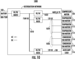
- FIG. 10 depicts an electrical architecture for a system 1000 using a high-voltage power source.
- the system 1000 includes the DC source 102 and similar loads (evaporator fan 112, condenser fan 114, auxiliary unit 116, compressor 120) as shown in FIG. 1 .
- the distribution network of FIG. 10 can include a distribution bus 1010.
- the distribution bus 1010 may be a high-voltage DC distribution bus that is coupled to the DC source 102 through a DC/DC boost converter.
- the distribution bus 1010 may be coupled to a compressor bus 1022, an evaporator bus 1024, and a condenser bus 1026.
- the evaporator bus 1024 and the condenser bus 1026 are coupled to a single DC/DC buck converter.
- the distribution bus may be further coupled to an auxiliary unit bus 130.
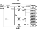
- FIG. 11 depicts an electrical architecture for a system 1100 using a high-voltage power source.
- the distribution network of FIG. 11 can include a DC/DC boost converter that is coupled to a DC source 102.
- the distribution bus 1110 may be a high-voltage DC distribution bus and may be coupled to a compressor bus 1122, an evaporator bus 1124, and a condenser bus 1126. In different embodiments, the distribution bus 1110 may further be coupled to an auxiliary unit bus 130.
- the compressor bus 1122 can include a DC/AC converter that is configured to convert the voltage of the distribution bus 1110 for the operation of the compressor 120.
- the DC/AC converter can be configured to convert the 750 VDC to 460 VAC to operate the compressor 120.
- the evaporator bus 1124 and the condenser bus 1126 can be coupled to the distribution bus 1110 through respective DC/DC buck converters.
- the evaporator bus 1124 and the condenser bus 1126 provide lower DC voltage for operation of the evaporator fan 112 and the condenser fan 114, respectively.
- the second distribution bus is further operable to provide power to an auxiliary unit 116.
- FIG. 12 depicts an electrical architecture for a system 1200 for a high-voltage power source.
- the distribution network of FIG. 12 can include a DC/DC boost converter that is coupled to a DC source 102.
- the distribution bus 1210 may be a high-voltage DC distribution bus, and may be coupled to a compressor bus 1222, an evaporator bus 1224, and a condenser bus 1226. In different embodiments, the distribution bus 1210 may further be coupled to an auxiliary unit bus 130.
- the compressor bus 1222 can include a DC/AC converter for the operation of the compressor 120.
- the DC/AC converter is configured to convert the voltage of the distribution bus 1210.
- the DC/AC converter can be configured to convert the 750 VDC to 460 VAC to operate the compressor 120.
- the evaporator bus 1224 can include a DC/AC converter to convert the voltage of the high-voltage DC distribution bus.
- the DC/AC converter can be configured to convert the 750 VDC to 460 VAC to operate the evaporator fan 112.
- the condenser bus 1226 can include a DC/AC converter to convert the voltage of the high-voltage DC distribution bus.
- the DC/AC converter can be configured to convert the 750 VDC to 460 VAC to operate the condenser fan 114.
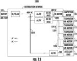
- FIG. 13 depicts an electrical architecture for a system 1300 using a high-voltage power source.
- the system 1300 includes the DC source 102 and similar loads (evaporator fan 112, condenser fan 114, auxiliary unit 116, compressor 120) as shown in FIG. 1 .
- the distribution network of FIG. 13 can include a distribution bus 1310.
- the distribution bus 1310 may be a high-voltage AC distribution bus that is coupled to the DC source 102 through the DC/DC/AC converter.
- the distribution bus 1310 may be coupled to a compressor bus 1322, an evaporator bus 1324, and a condenser bus 1326.
- the compressor bus 1322 may comprise an AC/DC converter that is coupled to a DC/DC buck converter that is further coupled to a motor.
- the AC/DC converter may be configured to convert the high-voltage AC from the distribution bus 1310 to DC voltage and the DC/DC buck converter may be operable to step-down the DC voltage, i.e., 48 VDC, to a voltage that is appropriate to operate the motor of the compressor.
- the evaporator bus 1324 and the condenser bus 1326 are coupled to high voltage AC distribution bus through the same AC/DC converter and DC/DC buck converter.
- FIG. 14 depicts an electrical architecture for a system 1400 using a high-voltage power source.
- the distribution network of FIG. 14 can include a converter that is coupled to a DC power source 102 and a distribution bus 1410.
- the converter may comprise a DC/DC/AC converter that is operable to convert the voltage from the DC power source 102 to high-voltage AC for distribution to various loads over a distribution bus 1410.
- the various loads may include loads such as the evaporator fan 112, the condenser fan 114, the auxiliary unit 116, and the compressor 120 shown in FIG. 1 .
- the distribution bus 1410 may be a high-voltage AC distribution bus, i.e., 480 VAC.
- the distribution bus 1410 may be coupled to a compressor bus 1422, an evaporator bus 1424, and a condenser bus 1426.
- the distribution bus 1410 may be coupled to an auxiliary unit bus 130 including, for example, a battery charger that is operable to charge a connected battery.
- the compressor bus 1422 may comprise an AC/DC converter that is coupled to a DC/DC buck converter that is further coupled to a motor.
- the AC/DC converter may be configured to convert the high-voltage AC from the distribution 1410 to DC voltage and the DC/DC buck converter may be operable to step-down the DC voltage, i.e., 48 VDC, to a voltage that is appropriate to operate the motor of the compressor.
- the evaporator bus 1424 and the condenser bus 1426 may each comprise an AC/DC converter that is coupled to a DC/DC buck converter to condition the power to operate the evaporator fan 112 and the condenser fan 114, respectively.
- FIG. 15 depicts an electrical architecture for a system 1500 using a high-voltage power source.
- the distribution network of FIG. 15 can include a converter that is coupled to a DC power source 102 and a distribution bus 1510.
- the converter may comprise a DC/DC/AC converter that is operable to convert the voltage from the DC power source 102 to high-voltage AC for distribution to various loads over the distribution bus 1510.
- the first stage of the DC/DC/AC converter can step-up the voltage of the DC source 102 to the appropriate level and then convert the DC to AC for the distribution bus 1510.
- the various loads may include such loads as the evaporator fan 112, the condenser fan 114, the auxiliary unit 116, and the compressor 120 shown in FIG. 1 .
- the distribution bus 1510 may be a high-voltage AC distribution bus, i.e., 480 VAC, and may be coupled to a compressor bus 1522, an evaporator bus 1524, and a condenser bus 1526. In a further embodiment, the distribution bus 1510 may be coupled to an auxiliary unit bus 130 including, for example, a battery charger that is operable to charge a connected battery.
- the compressor bus 1522 may comprise an AC/DC converter that is coupled to a DC/DC buck converter that is further coupled to a motor.
- the AC/DC converter may be configured to convert the high-voltage AC from the distribution 1510 to DC voltage and the DC/DC buck converter may be operable to step-down the DC voltage, i.e., 48 VDC, to a voltage that is appropriate to operate the motor of the compressor.
- the evaporator bus 1524 and condenser bus 1526 can each include an AC/DC converter that is coupled to a DC/AC converter.
- the AC/DC converter may convert the 480 VAC from the distribution bus to 750 VDC and the DC/AC converter may convert the 750 VDC to 460 VAC to provide power to operate the connected refrigerated equipment.
- FIG. 16 depicts an electrical architecture for a system 1600 using a high-voltage power source.
- the system 1600 includes the DC source 102 and similar loads (evaporator fan 112, condenser fan 114, auxiliary unit 116, compressor 120) as shown in FIG. 1 .
- the distribution network of FIG. 16 can include a distribution bus 1610.
- the distribution bus 1610 may be a low-voltage DC distribution bus that is coupled to the DC source 102 through a DC/DC buck converter.
- the distribution bus 1610 may be coupled to a compressor bus 1622, an evaporator bus 1624, and a condenser bus 1626.
- the evaporator bus and the condenser bus are coupled to the same DC/DC buck converter.
- the distribution bus may be further coupled to an auxiliary unit bus 130.
- FIG. 17 depicts an electrical architecture for a system 1700 using high-voltage power source.
- the distribution network of FIG. 17 can include a converter that is coupled to a DC power source 102 and a distribution bus 1710.
- the converter may comprise a DC/DC/AC converter that is operable to convert the power from the DC power source 102 to high-voltage AC for distribution to various loads over a distribution bus 1710.
- the various loads may include such loads as the evaporator fan 112, the condenser fan 114, the auxiliary unit 116, and the compressor 120 shown in FIG. 1 .
- the distribution bus 1710 may be a high-voltage AC distribution bus.
- the distribution bus 1710 of FIG. 12 may be coupled to a compressor bus 1722, an evaporator bus 1724, and a condenser bus 1726.
- the compressor bus 1722 can include an AC/DC converter that is coupled to a DC/AC converter.
- the AC/DC converter may convert the 480 VAC from the distribution bus to 750 VDC and the DC/AC converter may convert the 750 VDC to 460 VAC to provide power to operate the compressor 120.
- the evaporator bus 1724 and the condenser bus 1726 may each comprise an AC/DC converter that is coupled to a DC/DC buck converter to condition the power to operate the evaporator fan 112 and the condenser fan 114, respectively.
- FIG. 18 depicts an electrical architecture for a system 1800 having a high-voltage power source.
- the distribution network of FIG. 18 can include a converter that is coupled to a DC power source 102 and a distribution bus 1810.
- the converter may comprise a DC/DC/AC converter that is operable to convert the power from the DC power source 102 to high-voltage AC for distribution to various loads over a distribution bus 1810.
- the various loads may include such loads as the evaporator fan 112, the condenser fan 114, the auxiliary unit 116, and the compressor 120 shown in FIG. 1 .
- the distribution bus 1810 may be a high-voltage AC distribution bus, and may be coupled to a compressor bus 1822, an evaporator bus 1824, and a condenser bus 1826.
- the compressor bus can include an AC/DC converter that is coupled to a DC/AC converter.
- the AC/DC converter may convert the 480 VAC from the distribution bus to 750 VDC and the DC/AC converter may convert the 750 VDC to 460 VAC to provide power to operate the compressor 120.
- the evaporator bus 1824 and the condenser bus 1826 each comprise an AC/DC converter to convert the AC voltage from the distribution bus to a DC voltage and a DC/AC converter to convert the DC voltage from the AC/DC converter to operate the connected refrigeration equipment.
- FIG. 19 Shown in FIG. 19 is an embodiment of a tractor trailer system 100 for implementing one or more of the electrical architectures discussed with reference to FIGS. 1-18 .
- the tractor trailer system 1900 includes a tractor 1902 including an operator's compartment or cab 1904 and also including an engine, which acts as the drive system of the tractor trailer system 1900.
- a trailer 1906 is coupled to the tractor 1902.
- the trailer 1906 is a refrigerated trailer 1906 and includes a top wall 1908, a directly opposed bottom wall 1910, opposed side walls 1912, and a front wall 1914, with the front wall 1914 being closest to the tractor 1902.
- the trailer 1906 further includes a door or doors (not shown) at a rear wall 1916, opposite the front wall 1914.
- the walls of the trailer 1906 define a cargo compartment.
- the trailer 1906 is configured to maintain a cargo 1918 located inside the cargo compartment at a selected temperature through the use of a transport refrigeration unit 1920 located on the trailer 1906.
- the transport refrigeration unit 1920 is located at or attached to the front wall 1914.
Landscapes
- Engineering & Computer Science (AREA)
- Power Engineering (AREA)
- Physics & Mathematics (AREA)
- Thermal Sciences (AREA)
- Mechanical Engineering (AREA)
- General Engineering & Computer Science (AREA)
- Dc-Dc Converters (AREA)
- Inverter Devices (AREA)
Abstract
Description
- The present invention relates to transport refrigeration units, and more specifically, to medium-to-high voltage power systems for a transport refrigeration unit (TRU).
- Transport refrigeration units are used to cool cargo in a trailer or cargo container. Existing transport refrigeration units employ an engine and a generator to produce electrical power (e.g., AC power) to drive the compressor and fans (e.g., evaporator fans, condenser fans). Existing sources of AC power produce unregulated AC power that can vary in voltage and frequency. There may be a need for an all-electric solution for providing AC and DC power to the various loads for transport refrigeration units.
- According to a first aspect of the present invention, a high-voltage system of a transport refrigeration unit (TRU) is provided. The high-voltage system includes a high-voltage direct current (HVDC) source; and a first converter coupling the HVDC source to a distribution bus, wherein the distribution bus is coupled to a compressor, at least one condenser (e.g. at least one condenser fan), and an at least one evaporator (e.g. at least one evaporator fan).
- The distribution bus may be coupled to a compressor bus coupled to the compressor, a condenser bus coupled to the at least one condenser (e.g. at least one condenser fan), and an evaporator bus coupled to the at least one evaporator (e.g. at least one evaporator fan).
- The first converter may be a DC-DC buck converter configured to step down voltage from the HVDC source, and optionally the distribution bus is a low voltage DC bus.
- The compressor bus may comprise a DC motor that is mechanically coupled to an open drive compressor, wherein the evaporator bus and the condenser bus are coupled to at least one DC-DC buck converter that is used to convert voltage from the distribution bus for the at least one evaporator (e.g. at least one evaporator fan) and the at least one condenser (e.g. at least one condenser fan).
- Optionally, the system comprises: a compressor bus that comprises a DC motor that is mechanically coupled to an open drive compressor, an evaporator bus that comprises at least one first DC-DC buck converter to convert voltage from the distribution bus for the at least one evaporator (e.g. at least one evaporator fan), a condenser bus that comprises at least one second DC-DC buck converter to convert voltage from the distribution bus for the at least one condenser (e.g. at least one condenser fan), wherein the at least one first DC-DC buck converter and the at least one second DC-DC converter are different DC-DC converters.
- Optionally, the system comprises: a compressor bus that comprises a DC motor that is mechanically coupled to an open drive compressor, an evaporator bus that comprises a DC-DC boost converter coupled to a DC-AC converter to convert voltage from the distribution bus for the at least one evaporator (e.g. at least one evaporator fan), a condenser bus that comprises a DC-DC boost converter coupled to a DC-AC converter to convert voltage from the distribution bus for the at least one condenser (e.g. at least one condenser fan).
- Optionally, the system comprises: a compressor bus that comprises a DC-DC boost converter coupled to a DC-AC converter for the compressor, an evaporator bus and a condenser bus that are coupled to at least one DC-DC buck converter that is used to convert voltage from the distribution bus for the at least one evaporator (e.g. at least one evaporator fan) and the at least one condenser (e.g. at least one condenser fan).
- Optionally, the system comprises: a compressor bus that comprises a DC-DC boost converter coupled to a DC-AC converter for the compressor, an evaporator bus that comprises at least one first DC-DC buck converter to convert voltage from the distribution bus for the at least one evaporator (e.g. at least one evaporator fan), a condenser bus that comprises at least one second DC-DC buck converter to convert voltage from the distribution bus for the at least one condenser (e.g. at least one condenser fan), wherein the at least one first DC-DC buck converter and the at least one second DC-DC converter are different DC-DC converters.
- Optionally, the system comprises: a compressor bus that comprises a DC-DC boost converter coupled to a DC-AC converter, an evaporator bus that comprises a DC-DC boost converter coupled to a DC-AC converter, and a condenser bus that comprises a DC-DC boost converter coupled to a DC-AC converter.
- The first converter may be a DC-DC boost converter, and optionally wherein the distribution bus is a high-voltage DC distribution bus.
- Optionally, the system comprises: a compressor bus that comprises a DC-DC buck converter coupled to a DC motor that is further mechanically coupled to an open drive compressor, an evaporator bus and a condenser bus that are coupled to at least one DC-DC buck converter that is used to convert voltage from the distribution bus for the at least one evaporator (e.g. at least one evaporator fan) and the at least one condenser (e.g. at least one condenser fan).
- Optionally, the system comprises: a compressor bus that comprises a DC-DC buck converter coupled to a DC motor that is further mechanically coupled to an open drive compressor, an evaporator bus that comprises at least one first DC-DC buck converter to convert voltage from the distribution bus for the at least one evaporator (e.g. at least one evaporator fan), a condenser bus that comprises at least one second DC-DC buck converter to convert voltage from the distribution bus for the at least one condenser (e.g. at least one condenser fan), wherein the at least one first DC-DC buck converter and the at least one second DC-DC converter are different DC-DC converters.
- Optionally, the system comprises: a compressor bus that comprises a DC motor and a DC-DC buck converter to convert voltage from the distribution bus, wherein the DC motor is mechanically coupled to an open drive compressor, an evaporator bus that comprises a DC-AC converter to convert voltage from the distribution bus for the at least one evaporator (e.g. at least one evaporator fan), a condenser bus that comprises a DC-AC converter to convert voltage from the distribution bus for the at least one condenser (e.g. at least one condenser fan).
- Optionally the system comprises: a compressor bus that comprises a DC-AC converter to convert voltage from the distribution bus for the compressor, an evaporator bus and a condenser bus that are coupled to at least one DC-DC buck converter that is used to convert voltage from the distribution bus for the at least one evaporator (e.g. at least one evaporator fan) and the at least one condenser (e.g. at least one condenser fan).
- Optionally, the system comprises: a compressor bus that comprises a DC-AC converter to convert voltage from the distribution bus for the compressor, an evaporator bus that comprises at least one first DC-DC buck converter to convert voltage from the distribution bus for the at least one evaporator (e.g. at least one evaporator fan), a condenser bus that comprises at least one second DC-DC buck converter to convert voltage from the distribution bus for the at least one condenser (e.g. at least one condenser fan), wherein the at least one first DC-DC buck converter and the at least one second DC-DC converter are different DC-DC converters.
- Optionally, the system comprises: a compressor bus that comprises a DC-AC converter to convert voltage from the distribution bus for the compressor, an evaporator bus that comprises a DC-AC converter to convert voltage from the distribution bus for the at least one evaporator (e.g. at least one evaporator fan), a condenser bus that comprises a DC-AC converter to convert voltage from the distribution bus for the at least one condenser (e.g. at least one condenser fan).
- The first converter may be a DC-AC converter, and optionally wherein the distribution bus is an alternating current (AC) distribution bus.
- Optionally, the system comprises: a compressor bus that comprises a motor and an AC-DC converter coupled to a DC-DC buck converter, an evaporator bus and a condenser bus that are coupled to an AC-DC converter coupled to at least one DC-DC buck converter that is used to convert voltage from the distribution bus for the at least one evaporator (e.g. at least one evaporator fan) and the at least one condenser (e.g. at least one condenser fan).
- Optionally, the system comprises: a compressor bus that comprises a motor and an AC-DC converter coupled to a DC-DC buck converter, an evaporator bus that comprises at least one first AC-DC converter coupled to a first DC-DC buck converter to convert voltage from the distribution bus for the at least one evaporator (e.g. at least one evaporator fan), a condenser bus that comprises at least one second AC-DC converter coupled to a second DC-DC buck converter to convert voltage from the distribution bus for the at least one condenser (e.g. at least one condenser fan), wherein the at least one first AC-DC converter and the at least one second AC-DC converter are different AC-DC converters, and wherein the at least one first DC-DC buck converter and the at least one second DC-DC buck converter are different DC-DC buck converters.
- Optionally, the system comprises: a compressor bus that comprises an AC-DC converter coupled to a DC-AC converter, an evaporator bus that comprises an AC-DC converter coupled to a DC-AC converter, a condenser bus that comprises an AC-DC converter coupled to a DC-AC converter.
- Optionally, the system comprises a compressor bus that comprises an AC-DC converter coupled to a DC-AC converter, an evaporator bus and a condenser bus that are coupled to an AC-DC converter coupled to at least one DC-DC buck converter that is used to convert voltage from the distribution bus for the at least one evaporator (e.g. at least one evaporator fan) and the at least one condenser (e.g. at least one condenser fan).
- Optionally, the system comprises: a compressor bus that comprises an AC-DC converter coupled to a DC-AC converter, an evaporator bus that comprises at least one first AC-DC converter coupled to a first DC-DC buck converter to convert voltage from the distribution bus for the at least one evaporator (e.g. at least one evaporator fan), a condenser bus that comprises at least one second AC-DC converter coupled to a second DC-DC buck converter to convert voltage from the distribution bus for the at least one condenser (e.g. at least one condenser fan), wherein the at least one first AC-DC converter and the at least one second AC-DC converter are different AC-DC converters, and wherein the at least one first DC-DC buck converter and the at least one second DC-DC buck converter are different DC-DC buck converters.
- Optionally, the system comprises: a compressor bus that comprises an AC-DC converter coupled to a DC-AC converter, an evaporator bus that comprises an AC-DC converter coupled to a DC-AC converter, and a condenser bus that comprises an AC-DC converter coupled to a DC-AC converter.
- The high-voltage DC source may be between 100-750 volts.
- The foregoing features and elements may be combined in various combinations without exclusivity, unless expressly indicated otherwise. These features and elements as well as the operation thereof will become more apparent in light of the following description and the accompanying drawings. It should be understood, however, that the following description and drawings are intended to be illustrative and explanatory in nature and non-limiting.
- The following description of certain exemplary embodiments of the invention is provided by way of example only and should not be considered limiting. With reference to the accompanying drawings, like elements are numbered alike:
-
FIG. 1 depicts an exemplary electrical architecture for a transport refrigeration unit (TRU) configured to receive high-voltage power; -
FIG. 2 depicts an exemplary electrical architecture for a TRU configured to receive high-voltage power; -
FIG. 3 depicts an exemplary electrical architecture for a TRU configured to receive high-voltage power; -
FIG. 4 depicts an exemplary electrical architecture for a TRU configured to receive high-voltage power; -
FIG. 5 depicts an exemplary electrical architecture for a TRU configured to receive high-voltage power; -
FIG. 6 depicts an exemplary electrical architecture for a TRU configured to receive high-voltage power; -
FIG. 7 depicts an exemplary electrical architecture for a TRU configured to receive high-voltage power; -
FIG. 8 depicts an exemplary electrical architecture for a TRU configured to receive high-voltage power; -
FIG. 9 depicts an exemplary electrical architecture for a TRU configured to receive high-voltage power; -
FIG. 10 depicts an exemplary electrical architecture for a TRU configured to receive high-voltage power; -
FIG. 11 depicts an exemplary electrical architecture for a TRU configured to receive high-voltage power; -
FIG. 12 depicts an exemplary electrical architecture for a TRU configured to receive high-voltage power; -
FIG. 13 depicts an exemplary electrical architecture for a TRU configured to receive high-voltage power; -
FIG. 14 depicts an exemplary electrical architecture for a TRU configured to receive high-voltage power; -
FIG. 15 depicts an exemplary electrical architecture for a TRU configured to receive high-voltage power; -
FIG. 16 depicts an exemplary electrical architecture for a TRU configured to receive high-voltage power; -
FIG. 17 depicts an exemplary electrical architecture for a TRU configured to receive high-voltage power; -
FIG. 18 depicts an exemplary electrical architecture for a TRU configured to receive high-voltage power; and -
FIG. 19 depicts a tractor trailer system having a transport refrigeration unit and a cargo compartment for implementing an exemplary electrical architecture. -
FIG. 1 depicts an electrical architecture for asystem 100 using a high-voltage power source. As shown inFIG. 1 , thesystem 100 utilizes a direct current (DC) source as a source of power. In one or more embodiments of the disclosure, high-voltage can define a range of voltage between 100-750V. In a non-limiting example, the DC source is a high-voltage battery source, i.e., 350 VDC battery. - The distribution network of
FIG. 1 can include a DC/DC buck converter that is coupled to theDC source 102. The DC/DC buck converter can step-down the voltage of theDC source 102 for adistribution bus 104. As shown inFIG. 1 , thedistribution bus 104 is a low-voltage DC distribution bus, i.e., 48 VDC bus, that can be coupled to one or more loads such as a motor and/or a DC/DC buck converter. The motor may be mechanically coupled to acompressor 120, i.e., open drive compressor. The mechanical coupling of the motor to thecompressor 120 may comprise any known mechanical coupling. - The DC/DC buck converter is configured to reduce or step-down the voltage provided by the
distribution bus 104. Thedistribution bus 104 may be coupled to and operable to provide power to acompressor bus 122, an evaporator bus 124, and acondenser bus 126. In different embodiments, the distribution bus may be further coupled to anauxiliary unit bus 130. The voltage from thedistribution bus 104 is reduced when coupled to thecompressor bus 122, the evaporator bus 124, and thecondenser bus 126 using DC/DC buck converters. The evaporator bus 124 and thecondenser bus 126 may be coupled to a single DC/DC buck converter. Each of thecompressor bus 122, the evaporator bus 124, and thecondenser bus 126 may be a low voltage bus, i.e., 12 VDC bus, that is operable to provide power to one or more loads such asevaporator fans 112 and condenser fans 114. Theauxiliary unit bus 130 may be operable to provide power to anauxiliary unit 116 such as a battery. -
FIG. 2 depicts an electrical architecture for asystem 200 using a high-voltage power source. As shown inFIG. 2 , thesystem 200 includes theDC source 102 and similar loads (evaporator fan 112, condenser fan 114,auxiliary unit 116, compressor 120) as shown inFIG. 1 . The distribution network ofFIG. 2 can include adistribution bus 210. Thedistribution bus 210 may be a low-voltage DC distribution bus that is coupled to theDC source 102 through a DC/DC buck converter. Thedistribution bus 210 may be coupled to acompressor bus 222, anevaporator bus 224, and acondenser bus 226. As shown inFIG. 2 , theevaporator bus 224 and thecondenser bus 226 are coupled to respective DC/DC buck converters that are independent and different from one another. In different embodiments, the distribution bus may be further coupled to anauxiliary unit bus 130. -
FIG. 3 depicts an electrical architecture for asystem 300 using a high-voltage power source. As shown inFIG. 3 , thesystem 300 includes theDC source 102 and similar loads (evaporator fan 112, condenser fan 114,auxiliary unit 116, compressor 120) as shown inFIG. 1 . The distribution network ofFIG. 3 can include adistribution bus 310. Thedistribution bus 310 may be a low-voltage DC distribution bus that is coupled to theDC source 102 through a DC/DC buck converter. Thedistribution bus 310 may be coupled to acompressor bus 322, anevaporator bus 324, and acondenser bus 326. In different embodiments, the distribution bus may be further coupled to anauxiliary unit bus 130. - The
compressor bus 322 can include a motor, where the motor is operably coupled to thecompressor 120. Anevaporator bus 324 and acondenser bus 326 can each include a DC/DC boost converter that can be coupled to a DC/AC converter, where theevaporator bus 324 and thecondenser bus 326 can be further coupled to thedistribution bus 310 through respective DC/DC boost converters. DC/DC boost converters are configured to increase or step-up the 48 VDC to 750 VDC and DC/AC converters are configured to convert the 750 VDC to 460 VAC that is provided for the operation of theevaporator fan 112 and the condenser fan 114, respectively. Theauxiliary unit bus 130 may include a DC/DC buck converter to step-down the voltage of thedistribution bus 310 to an appropriate voltage for any connectedauxiliary units 116. -
FIG. 4 depicts an electrical architecture for asystem 400 using a high-voltage power source. As shown inFIG. 4 , thesystem 400 includes theDC source 102 and similar loads (evaporator fan 112, condenser fan 114,auxiliary unit 116, compressor 120) as shown inFIG. 1 . The distribution network ofFIG. 4 can include adistribution bus 410. Thedistribution bus 410 may be a low-voltage DC distribution bus that is coupled to theDC source 102 through a DC/DC buck converter. Thedistribution bus 410 may be coupled to acompressor bus 422, anevaporator bus 424, and acondenser bus 426. As shown inFIG. 4 , theevaporator bus 424 and thecondenser bus 426 are coupled to a single DC/DC buck converter. In different embodiments, the distribution bus may be further coupled to anauxiliary unit bus 130. -
FIG. 5 depicts an electrical architecture of asystem 500 for a high-voltage power source. As shown inFIG. 5 , thesystem 500 includes theDC source 102 and similar loads (evaporator fan 112, condenser fan 114,auxiliary load 116, compressor 120) as shown inFIG. 1 . Thedistribution bus 510 may be a low-voltage DC distribution bus that is coupled to theDC source 102 through a DC/DC buck converter. The distribution network ofFIG. 5 may include adistribution bus 510 that is coupled to acompressor bus 522, anevaporator bus 524, and acondenser bus 526. In different embodiments, thedistribution bus 510 may further be coupled to anauxiliary unit bus 130. - The
compressor bus 522 can include a DC/DC boost converter that is coupled to a DC/AC converter (inverter). In this non-limiting example, the DC/DC boost converter is configured to increase or step-up the 48 VDC to 750 VDC, and the DC/AC converter is configured to convert the 750 VDC to 460 VAC that is provided for the operation of thecompressor 120. - The
evaporator bus 524 can include a DC/DC buck converter that is configured to step-down the voltage of thedistribution bus 310 from 48 VDC to 12 VDC for the operation of theevaporator fan 112. Similarly, thecondenser bus 526 can include a DC/DC buck converter that is configured step-down the voltage of thedistribution bus 310 from 48 VDC to 12 VDC for the operation of the condenser fan 114. -
FIG. 6 depicts an electrical architecture for asystem 600 using a high-voltage power source. As shown inFIG. 6 , thesystem 600 includes theDC source 102 and similar loads (evaporator fan 112, condenser fan 114,auxiliary load 116, compressor 120) as shown inFIG. 1 . Thedistribution bus 610 may be a low-voltage DC distribution bus that is coupled to theDC source 102 through a DC/DC buck converter. The distribution network ofFIG. 6 may be adistribution bus 610 that is coupled to acompressor bus 622, anevaporator bus 624, and acondenser bus 626. In different embodiments, thedistribution bus 610 may further be coupled to anauxiliary unit bus 130. - The
compressor bus 622 can include a DC/DC boost converter that is coupled to a DC/AC converter. In this non-limiting example, the DC-DC boost converter is configured to increase the 48 VDC to 750 VDC and the DC/AC converter is configured to convert the 750 VDC to 460 VAC that is provided for the operation of thecompressor 120. - Similarly, the
evaporator bus 624 and thecondenser bus 626 each include a DC-DC boost converter that is coupled to a DC/AC converter. In this non-limiting example, each DC-DC boost converter is configured to increase or step-up the 48 VDC to 750 VDC and each DC/AC converter is configured to convert the 750 VDC to 460 VAC to operate theevaporator fan 112 and the condenser fan 114, respectively. -
FIG. 7 depicts an electrical architecture for asystem 700 using a high-voltage power source. As shown inFIG. 7 , thesystem 700 includes theDC source 102 and similar loads (evaporator fan 112, condenser fan 114,auxiliary unit 116, compressor 120) as shown inFIG. 1 . The distribution network ofFIG. 7 can include adistribution bus 710. Thedistribution bus 710 may be a high-voltage DC distribution bus that is coupled to theDC source 102 through a DC/DC boost converter. Thedistribution bus 710 may be coupled to acompressor bus 722, anevaporator bus 724, and acondenser bus 726. As shown inFIG. 7 , theevaporator bus 724 and thecondenser bus 726 are coupled to a single DC-DC buck converter. In different embodiments, the distribution bus may be further coupled to anauxiliary unit bus 130. -
FIG. 8 depicts an electrical architecture for asystem 800 using a high-voltage power source. The distribution network ofFIG. 8 can include a DC/DC boost converter that is coupled to aDC source 102. The DC/DC boost converter can step-up the voltage of theDC source 102 for adistribution bus 810. Thedistribution bus 810 may be a high-voltage DC distribution bus, and may be coupled to acompressor bus 822, anevaporator bus 824, and acondenser bus 826. In different embodiments, thedistribution bus 810 may further be coupled to anauxiliary unit bus 130. - The
compressor bus 822 can include a DC/DC buck converter coupled to a motor used to drive acompressor 120. The DC/DC buck converter can be configured to step-down the voltage of the high-voltage DC distribution bus. Theevaporator bus 824 can include a DC/DC buck converter to step-down the voltage of the high-voltage DC distribution bus to a lower DC voltage for operation of theevaporator fan 112. Similarly, thecondenser bus 826 may comprise a DC/DC buck converter to step-down the voltage of the high-voltage DC distribution bus to a lower DC voltage for operation of the condenser fan 114. -
FIG. 9 depicts an electrical architecture for asystem 900 using a high-voltage power source. The distribution network ofFIG. 9 can include a DC/DC boost converter that is coupled to aDC source 102. Thedistribution bus 910 may be a high-voltage DC distribution bus, and may be coupled to acompressor bus 922, anevaporator bus 924, and acondenser bus 926. In different embodiments, thedistribution bus 910 may further be coupled to anauxiliary unit bus 130. - The
compressor bus 922 may comprise a DC/DC buck converter coupled to a motor used to drive acompressor 120. The DC/DC buck converter can be configured to step-down the voltage of the high-voltage DC distribution bus. Theevaporator bus 924 can include a DC/AC converter to convert the voltage of the high-voltage DC distribution bus. For example, the DC/AC converter can be configured to convert the 750 VDC to 460 VAC to operate theevaporator fan 112. Similarly, thecondenser bus 926 can include a DC/AC converter to convert the power of the high-voltage DC distribution bus. For example, the DC/AC converter can be configured to convert the 750 VDC to 460 VAC to operate the condenser fan 114. -
FIG. 10 depicts an electrical architecture for asystem 1000 using a high-voltage power source. As shown inFIG. 10 , thesystem 1000 includes theDC source 102 and similar loads (evaporator fan 112, condenser fan 114,auxiliary unit 116, compressor 120) as shown inFIG. 1 . The distribution network ofFIG. 10 can include adistribution bus 1010. Thedistribution bus 1010 may be a high-voltage DC distribution bus that is coupled to theDC source 102 through a DC/DC boost converter. Thedistribution bus 1010 may be coupled to acompressor bus 1022, anevaporator bus 1024, and acondenser bus 1026. As shown inFIG. 10 , theevaporator bus 1024 and thecondenser bus 1026 are coupled to a single DC/DC buck converter. In different embodiments, the distribution bus may be further coupled to anauxiliary unit bus 130. -
FIG. 11 depicts an electrical architecture for asystem 1100 using a high-voltage power source. The distribution network ofFIG. 11 can include a DC/DC boost converter that is coupled to aDC source 102. Thedistribution bus 1110 may be a high-voltage DC distribution bus and may be coupled to acompressor bus 1122, anevaporator bus 1124, and acondenser bus 1126. In different embodiments, thedistribution bus 1110 may further be coupled to anauxiliary unit bus 130. - The
compressor bus 1122 can include a DC/AC converter that is configured to convert the voltage of thedistribution bus 1110 for the operation of thecompressor 120. For example, the DC/AC converter can be configured to convert the 750 VDC to 460 VAC to operate thecompressor 120. Theevaporator bus 1124 and thecondenser bus 1126 can be coupled to thedistribution bus 1110 through respective DC/DC buck converters. Theevaporator bus 1124 and thecondenser bus 1126 provide lower DC voltage for operation of theevaporator fan 112 and the condenser fan 114, respectively. In other embodiments, the second distribution bus is further operable to provide power to anauxiliary unit 116. -
FIG. 12 depicts an electrical architecture for asystem 1200 for a high-voltage power source. The distribution network ofFIG. 12 can include a DC/DC boost converter that is coupled to aDC source 102. Thedistribution bus 1210 may be a high-voltage DC distribution bus, and may be coupled to acompressor bus 1222, anevaporator bus 1224, and acondenser bus 1226. In different embodiments, thedistribution bus 1210 may further be coupled to anauxiliary unit bus 130. - The
compressor bus 1222 can include a DC/AC converter for the operation of thecompressor 120. The DC/AC converter is configured to convert the voltage of thedistribution bus 1210. For example, the DC/AC converter can be configured to convert the 750 VDC to 460 VAC to operate thecompressor 120. - The
evaporator bus 1224 can include a DC/AC converter to convert the voltage of the high-voltage DC distribution bus. For example, the DC/AC converter can be configured to convert the 750 VDC to 460 VAC to operate theevaporator fan 112. Similarly, thecondenser bus 1226 can include a DC/AC converter to convert the voltage of the high-voltage DC distribution bus. For example, the DC/AC converter can be configured to convert the 750 VDC to 460 VAC to operate the condenser fan 114. -
FIG. 13 depicts an electrical architecture for asystem 1300 using a high-voltage power source. As shown inFIG. 13 , thesystem 1300 includes theDC source 102 and similar loads (evaporator fan 112, condenser fan 114,auxiliary unit 116, compressor 120) as shown inFIG. 1 . The distribution network ofFIG. 13 can include adistribution bus 1310. Thedistribution bus 1310 may be a high-voltage AC distribution bus that is coupled to theDC source 102 through the DC/DC/AC converter. Thedistribution bus 1310 may be coupled to acompressor bus 1322, anevaporator bus 1324, and acondenser bus 1326. - The
compressor bus 1322 may comprise an AC/DC converter that is coupled to a DC/DC buck converter that is further coupled to a motor. The AC/DC converter may be configured to convert the high-voltage AC from thedistribution bus 1310 to DC voltage and the DC/DC buck converter may be operable to step-down the DC voltage, i.e., 48 VDC, to a voltage that is appropriate to operate the motor of the compressor. - The
evaporator bus 1324 and thecondenser bus 1326 are coupled to high voltage AC distribution bus through the same AC/DC converter and DC/DC buck converter. -
FIG. 14 depicts an electrical architecture for asystem 1400 using a high-voltage power source. The distribution network ofFIG. 14 can include a converter that is coupled to aDC power source 102 and adistribution bus 1410. The converter may comprise a DC/DC/AC converter that is operable to convert the voltage from theDC power source 102 to high-voltage AC for distribution to various loads over adistribution bus 1410. The various loads may include loads such as theevaporator fan 112, the condenser fan 114, theauxiliary unit 116, and thecompressor 120 shown inFIG. 1 . - The
distribution bus 1410 may be a high-voltage AC distribution bus, i.e., 480 VAC. Thedistribution bus 1410 may be coupled to acompressor bus 1422, anevaporator bus 1424, and acondenser bus 1426. In a further embodiment, thedistribution bus 1410 may be coupled to anauxiliary unit bus 130 including, for example, a battery charger that is operable to charge a connected battery. - The
compressor bus 1422 may comprise an AC/DC converter that is coupled to a DC/DC buck converter that is further coupled to a motor. The AC/DC converter may be configured to convert the high-voltage AC from thedistribution 1410 to DC voltage and the DC/DC buck converter may be operable to step-down the DC voltage, i.e., 48 VDC, to a voltage that is appropriate to operate the motor of the compressor. - The
evaporator bus 1424 and thecondenser bus 1426 may each comprise an AC/DC converter that is coupled to a DC/DC buck converter to condition the power to operate theevaporator fan 112 and the condenser fan 114, respectively. -
FIG. 15 depicts an electrical architecture for asystem 1500 using a high-voltage power source. The distribution network ofFIG. 15 can include a converter that is coupled to aDC power source 102 and adistribution bus 1510. The converter may comprise a DC/DC/AC converter that is operable to convert the voltage from theDC power source 102 to high-voltage AC for distribution to various loads over thedistribution bus 1510. The first stage of the DC/DC/AC converter can step-up the voltage of theDC source 102 to the appropriate level and then convert the DC to AC for thedistribution bus 1510. The various loads may include such loads as theevaporator fan 112, the condenser fan 114, theauxiliary unit 116, and thecompressor 120 shown inFIG. 1 . - The
distribution bus 1510 may be a high-voltage AC distribution bus, i.e., 480 VAC, and may be coupled to acompressor bus 1522, anevaporator bus 1524, and acondenser bus 1526. In a further embodiment, thedistribution bus 1510 may be coupled to anauxiliary unit bus 130 including, for example, a battery charger that is operable to charge a connected battery. - The
compressor bus 1522 may comprise an AC/DC converter that is coupled to a DC/DC buck converter that is further coupled to a motor. The AC/DC converter may be configured to convert the high-voltage AC from thedistribution 1510 to DC voltage and the DC/DC buck converter may be operable to step-down the DC voltage, i.e., 48 VDC, to a voltage that is appropriate to operate the motor of the compressor. Theevaporator bus 1524 andcondenser bus 1526 can each include an AC/DC converter that is coupled to a DC/AC converter. The AC/DC converter may convert the 480 VAC from the distribution bus to 750 VDC and the DC/AC converter may convert the 750 VDC to 460 VAC to provide power to operate the connected refrigerated equipment. -
FIG. 16 depicts an electrical architecture for asystem 1600 using a high-voltage power source. As shown inFIG. 16 , thesystem 1600 includes theDC source 102 and similar loads (evaporator fan 112, condenser fan 114,auxiliary unit 116, compressor 120) as shown inFIG. 1 . The distribution network ofFIG. 16 can include adistribution bus 1610. Thedistribution bus 1610 may be a low-voltage DC distribution bus that is coupled to theDC source 102 through a DC/DC buck converter. Thedistribution bus 1610 may be coupled to acompressor bus 1622, anevaporator bus 1624, and acondenser bus 1626. As shown inFIG. 16 , the evaporator bus and the condenser bus are coupled to the same DC/DC buck converter. In different embodiments, the distribution bus may be further coupled to anauxiliary unit bus 130. -
FIG. 17 depicts an electrical architecture for asystem 1700 using high-voltage power source. The distribution network ofFIG. 17 can include a converter that is coupled to aDC power source 102 and adistribution bus 1710. The converter may comprise a DC/DC/AC converter that is operable to convert the power from theDC power source 102 to high-voltage AC for distribution to various loads over adistribution bus 1710. The various loads may include such loads as theevaporator fan 112, the condenser fan 114, theauxiliary unit 116, and thecompressor 120 shown inFIG. 1 . - The
distribution bus 1710 may be a high-voltage AC distribution bus. Thedistribution bus 1710 ofFIG. 12 may be coupled to acompressor bus 1722, anevaporator bus 1724, and acondenser bus 1726. Thecompressor bus 1722 can include an AC/DC converter that is coupled to a DC/AC converter. The AC/DC converter may convert the 480 VAC from the distribution bus to 750 VDC and the DC/AC converter may convert the 750 VDC to 460 VAC to provide power to operate thecompressor 120. - The
evaporator bus 1724 and thecondenser bus 1726 may each comprise an AC/DC converter that is coupled to a DC/DC buck converter to condition the power to operate theevaporator fan 112 and the condenser fan 114, respectively. -
FIG. 18 depicts an electrical architecture for asystem 1800 having a high-voltage power source. The distribution network ofFIG. 18 can include a converter that is coupled to aDC power source 102 and adistribution bus 1810. The converter may comprise a DC/DC/AC converter that is operable to convert the power from theDC power source 102 to high-voltage AC for distribution to various loads over adistribution bus 1810. The various loads may include such loads as theevaporator fan 112, the condenser fan 114, theauxiliary unit 116, and thecompressor 120 shown inFIG. 1 . - The
distribution bus 1810 may be a high-voltage AC distribution bus, and may be coupled to acompressor bus 1822, anevaporator bus 1824, and acondenser bus 1826. The compressor bus can include an AC/DC converter that is coupled to a DC/AC converter. The AC/DC converter may convert the 480 VAC from the distribution bus to 750 VDC and the DC/AC converter may convert the 750 VDC to 460 VAC to provide power to operate thecompressor 120. Similarly, theevaporator bus 1824 and thecondenser bus 1826 each comprise an AC/DC converter to convert the AC voltage from the distribution bus to a DC voltage and a DC/AC converter to convert the DC voltage from the AC/DC converter to operate the connected refrigeration equipment. - Shown in
FIG. 19 is an embodiment of atractor trailer system 100 for implementing one or more of the electrical architectures discussed with reference toFIGS. 1-18 . Thetractor trailer system 1900 includes atractor 1902 including an operator's compartment orcab 1904 and also including an engine, which acts as the drive system of thetractor trailer system 1900. Atrailer 1906 is coupled to thetractor 1902. Thetrailer 1906 is arefrigerated trailer 1906 and includes atop wall 1908, a directly opposedbottom wall 1910, opposedside walls 1912, and afront wall 1914, with thefront wall 1914 being closest to thetractor 1902. Thetrailer 1906 further includes a door or doors (not shown) at arear wall 1916, opposite thefront wall 1914. The walls of thetrailer 1906 define a cargo compartment. Thetrailer 1906 is configured to maintain acargo 1918 located inside the cargo compartment at a selected temperature through the use of atransport refrigeration unit 1920 located on thetrailer 1906. Thetransport refrigeration unit 1920, as shown inFIG. 19 , is located at or attached to thefront wall 1914. - A detailed description of one or more embodiments of the disclosed apparatus and method are presented herein by way of exemplification and not limitation with reference to the Figures.
- The term "about" is intended to include the degree of error associated with measurement of the particular quantity based upon the equipment available at the time of filing the application.
- The terminology used herein is for the purpose of describing particular embodiments only and is not intended to be limiting of the present invention. As used herein, the singular forms "a", "an" and "the" are intended to include the plural forms as well, unless the context clearly indicates otherwise. It will be further understood that the terms "comprises" and/or "comprising," when used in this specification, specify the presence of stated features, integers, steps, operations, elements, and/or components, but do not preclude the presence or addition of one or more other features, integers, steps, operations, element components, and/or groups thereof.
- While the present invention has been described with reference to an exemplary embodiment or embodiments, it will be understood by those skilled in the art that various changes may be made and equivalents may be substituted for elements thereof without departing from the scope of the present invention, as defined in the appended claims. In addition, many modifications may be made to adapt a particular situation or material to the teachings of the present invention without departing from the scope thereof. Therefore, it is intended that the present invention not be limited to the particular embodiment described as a best mode contemplated for carrying out this present invention, but that the present invention will include all embodiments falling within the scope of the claims.
- The following clauses set out aspects of the invention which may or may not be currently claimed, but which may provide basis for future amendment(s) and/or a divisional application:
- 1. A high-voltage system of a transport refrigeration unit (TRU), the system comprising:
- a high-voltage direct current (HVDC) source;
- a first converter coupling the HVDC source to a distribution bus,
- wherein the distribution bus is coupled to a compressor, at least one condenser fan, and at least one evaporator fan.
- 2. The high-voltage system of
clause 1, wherein the distribution bus is coupled to a compressor bus coupled to the compressor, a condenser bus coupled to the at least one condenser fan, and an evaporator bus coupled to the at least one evaporator fan. - 3. The high-voltage system of clause 2, wherein the first converter is a DC-DC buck converter configured to step down voltage from the HVDC source, wherein the distribution bus is a low voltage DC bus.
- 4. The high-voltage system of
clause 3,- wherein the compressor bus comprises a DC motor that is mechanically coupled to an open drive compressor,
- wherein the evaporator bus and the condenser bus are coupled to at least one DC-DC buck converter that is used to convert voltage from the distribution bus for the at least one evaporator fan and the at least one condenser fan.
- 5. The high-voltage system of
clause 3,- wherein the compressor bus comprises a DC motor that is mechanically coupled to an open drive compressor,
- wherein the evaporator bus comprises at least one first DC-DC buck converter to convert voltage from the distribution bus for the at least one evaporator fan,
- wherein the condenser bus comprises at least one second DC-DC buck converter to convert voltage from the distribution bus for the at least one condenser fan, wherein the at least one first DC-DC buck converter and the at least one second DC-DC converter are different DC-DC converters.
- 6. The high-voltage system of
clause 3,- wherein the compressor bus comprises a DC motor that is mechanically coupled to an open drive compressor,
- wherein the evaporator bus comprises a DC-DC boost converter coupled to a DC-AC converter to convert voltage from the distribution bus for the at least one evaporator fan,
- wherein the condenser bus comprises a DC-DC boost converter coupled to a DC-AC converter to convert voltage from the distribution bus for the at least one condenser fan.
- 7. The high-voltage system of
clause 3,- wherein the compressor bus comprises a DC-DC boost converter coupled to a DC-AC converter for the compressor,
- wherein the evaporator bus and the condenser bus are coupled to at least one DC-DC buck converter that is used to convert voltage from the distribution bus for the at least one evaporator fan and the at least one condenser fan.
- 8. The high-voltage system of
clause 3,- wherein the compressor bus comprises a DC-DC boost converter coupled to a DC-AC converter for the compressor fan,
- wherein the evaporator bus comprises at least one first DC-DC buck converter to convert voltage from the distribution bus for the at least one evaporator fan,
- wherein the condenser bus comprises at least one second DC-DC buck converter to convert voltage from the distribution bus for the at least one condenser fan, wherein the at least one first DC-DC buck converter and the at least one second DC-DC converter are different DC-DC converters.
- 9. The high-voltage system of
clause 3,- wherein the compressor bus comprises a DC-DC boost converter coupled to a DC-AC converter,
- wherein the evaporator bus comprises a DC-DC boost converter coupled to a DC-AC converter, and
- wherein the condenser bus comprises a DC-DC boost converter coupled to a DC-AC converter.
- 10. The system of clause 2, wherein the first converter is a DC-DC boost converter, wherein the distribution bus is a high-voltage DC distribution bus.
- 11. The high-voltage system of clause 10,
- wherein the compressor bus comprises a DC-DC buck converter coupled to a DC motor that is further mechanically coupled to an open drive compressor,
- wherein the evaporator bus and the condenser bus are coupled to at least one DC-DC buck converter that is used to convert voltage from the distribution bus for the at least one evaporator fan and the at least one condenser fan.
- 12. The high-voltage system of clause 10,
- wherein the compressor bus comprises a DC-DC buck converter coupled to a DC motor that is further mechanically coupled to an open drive compressor,
- wherein the evaporator bus comprises at least one first DC-DC buck converter to convert voltage from the distribution bus for the at least one evaporator fan,
- wherein the condenser bus comprises at least one second DC-DC buck converter to convert voltage from the distribution bus for the at least one condenser fan, wherein the at least one first DC-DC buck converter and the at least one second DC-DC converter are different DC-DC converters.
- 13. The high-voltage system of clause 10,
- wherein the compressor bus comprises a DC motor and a DC-DC buck converter to convert voltage from the distribution bus, wherein the DC motor is mechanically coupled to an open drive compressor,
- wherein the evaporator bus comprises a DC-AC converter to convert voltage from the distribution bus for the at least one evaporator fan,
- wherein condenser bus comprises a DC-AC converter to convert voltage from the distribution bus for the at least one condenser fan.
- 14. The high-voltage system of clause 10,
- wherein the compressor bus comprises a DC-AC converter to convert voltage from the distribution bus for the compressor,
- wherein the evaporator bus and the condenser bus are coupled to at least one DC-DC buck converter that is used to convert voltage from the distribution bus for the at least one evaporator fan and the at least one condenser fan.
- 15. The high-voltage system of clause 10,
- wherein the compressor bus comprises a DC-AC converter to convert voltage from the distribution bus for the compressor,
- wherein the evaporator bus comprises at least one first DC-DC buck converter to convert voltage from the distribution bus for the at least one evaporator fan,
- wherein the condenser bus comprises at least one second DC-DC buck converter to convert voltage from the distribution bus for the at least one condenser fan, wherein the at least one first DC-DC buck converter and the at least one second DC-DC converter are different DC-DC converters.
- 16. The high-voltage system of clause 10,
- wherein the compressor bus comprises a DC-AC converter to convert voltage from the distribution bus for the compressor,
- wherein the evaporator bus comprises a DC-AC converter to convert voltage from the distribution bus for the at least one evaporator fan,
- wherein the condenser bus comprises a DC-AC converter to convert voltage from the distribution bus for the at least one condenser fan.
- 17. The high-voltage system of clause 2, wherein the first converter is a DC-AC converter, wherein the distribution bus is an alternating current (AC) distribution bus.
- 18. The high-voltage system of clause 17,
- wherein the compressor bus comprises a motor and an AC-DC converter coupled to a DC-DC buck converter,
- wherein the evaporator bus and the condenser bus are coupled to an AC-DC converter coupled to at least one DC-DC buck converter that is used to convert voltage from the distribution bus for the at least one evaporator fan and the at least one condenser fan.
- 19. The high-voltage system of clause 17,
- wherein the compressor bus comprises a motor and an AC-DC converter coupled to a DC-DC buck converter,
- wherein the evaporator bus comprises at least one first AC-DC converter coupled to a first DC-DC buck converter to convert voltage from the distribution bus for the at least one evaporator fan,
- wherein the condenser bus comprises at least one second AC-DC converter coupled to a second DC-DC buck converter to convert voltage from the distribution bus for the at least one condenser fan, wherein the at least one first AC-DC converter and the at least one second AC-DC converter are different AC-DC converters wherein the at least one first DC-DC buck converter and the at least one second DC-DC buck converter are different DC-DC buck converters.
- 20. The high-voltage system of clause 17,
- wherein the compressor bus comprises an AC-DC converter coupled to a DC-AC converter,
- wherein the evaporator bus comprises an AC-DC converter coupled to a DC-AC converter,
- wherein the condenser bus comprises an AC-DC converter coupled to a DC-AC converter.
- 21. The high-voltage system of clause 17,
- wherein the compressor bus comprises an AC-DC converter coupled to a DC-AC converter,
- wherein the evaporator bus and the condenser bus are coupled to an AC-DC converter coupled to at least one DC-DC buck converter that is used to convert voltage from the distribution bus for the at least one evaporator fan and the at least one condenser fan.
- 22. The high-voltage system of clause 17,
- wherein the compressor bus comprises an AC-DC converter coupled to a DC-AC converter,
- wherein the evaporator bus comprises at least one first AC-DC converter coupled to a first DC-DC buck converter to convert voltage from the distribution bus for the at least one evaporator fan,
- wherein the condenser bus comprises at least one second AC-DC converter coupled to a second DC-DC buck converter to convert voltage from the distribution bus for the at least one condenser fan, wherein the at least one first AC-DC converter and the at least one second AC-DC converter are different AC-DC converters wherein the at least one first DC-DC buck converter and the at least one second DC-DC buck converter are different DC-DC buck converters.
- 23. The high-voltage system of clause 17,
- wherein the compressor bus comprises an AC-DC converter coupled to a DC-AC converter,
- wherein the evaporator bus comprises an AC-DC converter coupled to a DC-AC converter,
- wherein the condenser bus comprises an AC-DC converter coupled to a DC-AC converter. (
FIG. 18 )
- 24. The high-voltage system of
clause 1, wherein the high-voltage DC source is between 100-750 volts.
Claims (15)
- A high-voltage system (100-1800) of a transport refrigeration unit (TRU) (1920), the system (100-1800) comprising:a high-voltage direct current (HVDC) source (102);a first converter coupling the HVDC source (102) to a distribution bus (104; 210-1810),wherein the distribution bus (104; 210-1810) is coupled to a compressor (120), at least one condenser fan (114), and at least one evaporator fan (112).
- The high-voltage system (100-1800) of claim 1, wherein the distribution bus (104; 210-1810) is coupled to a compressor bus (122-1822) coupled to the compressor (120), a condenser bus (126-1826) coupled to the at least one condenser fan (114), and an evaporator bus (124-1824) coupled to the at least one evaporator fan (112).
- The high-voltage system (100-600) of claim 2, wherein the first converter is a DC-DC buck converter configured to step down voltage from the HVDC source (102), and wherein the distribution bus (104; 210-610) is a low voltage DC bus.
- The high-voltage system (100; 200) of claim 3,wherein the compressor bus (122; 222) comprises a DC motor that is mechanically coupled to an open drive compressor (120), andwherein the evaporator bus (124; 224) and the condenser bus (126; 226) are coupled to at least one DC-DC buck converter that is used to convert voltage from the distribution bus (104; 210) for the at least one evaporator fan (112) and the at least one condenser fan (114); orwherein the compressor bus (222) comprises a DC motor that is mechanically coupled to an open drive compressor (120),wherein the evaporator bus (224) comprises at least one first DC-DC buck converter to convert voltage from the distribution bus (210) for the at least one evaporator fan (112), andwherein the condenser bus (226) comprises at least one second DC-DC buck converter to convert voltage from the distribution bus (210) for the at least one condenser fan (114), wherein the at least one first DC-DC buck converter and the at least one second DC-DC converter are different DC-DC converters.
- The high-voltage system (300; 600) of claim 3,wherein the compressor bus (322) comprises: a DC motor that is mechanically coupled to an open drive compressor (120); or a DC-DC boost converter coupled to a DC-AC converter; andwherein the evaporator bus (324; 624) comprises a DC-DC boost converter coupled to a DC-AC converter to convert voltage from the distribution bus (310; 610) for the at least one evaporator fan (112), andwherein the condenser bus (326; 626) comprises a DC-DC boost converter coupled to a DC-AC converter to convert voltage from the distribution bus (310; 610) for the at least one condenser fan (114).
- The high-voltage system (400; 500) of claim 3,wherein the compressor bus (422; 522) comprises a DC-DC boost converter coupled to a DC-AC converter for the compressor (120), andwherein the evaporator bus (424; 524) and the condenser bus (426; 526) are coupled to at least one DC-DC buck converter that is used to convert voltage from the distribution bus (410; 510) for the at least one evaporator fan (112) and the at least one condenser fan (114); orwherein the compressor bus (522) comprises a DC-DC boost converter coupled to a DC-AC converter for the compressor (120),wherein the evaporator bus (524) comprises at least one first DC-DC buck converter to convert voltage from the distribution bus (510) for the at least one evaporator fan (112), andwherein the condenser bus (526) comprises at least one second DC-DC buck converter to convert voltage from the distribution bus (510) for the at least one condenser fan (114), wherein the at least one first DC-DC buck converter and the at least one second DC-DC converter are different DC-DC converters.
- The system (700- 1200) of claim 2, wherein the first converter is a DC-DC boost converter, and wherein the distribution bus (710-1210) is a high-voltage DC distribution bus.
- The high-voltage system (700; 800) of claim 7,wherein the compressor bus (722; 822) comprises a DC-DC buck converter coupled to a DC motor that is further mechanically coupled to an open drive compressor (120), andwherein the evaporator bus (724; 824) and the condenser bus (726; 826) are coupled to at least one DC-DC buck converter that is used to convert voltage from the distribution bus (710; 810) for the at least one evaporator fan (112) and the at least one condenser fan (114); orwherein the compressor bus (822) comprises a DC-DC buck converter coupled to a DC motor that is further mechanically coupled to an open drive compressor (120),wherein the evaporator bus (824) comprises at least one first DC-DC buck converter to convert voltage from the distribution bus (810) for the at least one evaporator fan (112), andwherein the condenser bus (826) comprises at least one second DC-DC buck converter to convert voltage from the distribution bus (810) for the at least one condenser fan (114), wherein the at least one first DC-DC buck converter and the at least one second DC-DC converter are different DC-DC converters.
- The high-voltage system (900; 1200) of claim 7,wherein the compressor bus (922) comprises: a DC motor and a DC-DC buck converter to convert voltage from the distribution bus (910), wherein the DC motor is mechanically coupled to an open drive compressor (120); or a DC-AC converter to convert voltage from the distribution bus (1210) for the compressor (120),wherein the evaporator bus (924; 1224) comprises a DC-AC converter to convert voltage from the distribution bus (910; 1210) for the at least one evaporator fan (112), andwherein the condenser bus (926; 1226) comprises a DC-AC converter to convert voltage from the distribution bus (910; 1210) for the at least one condenser fan (114).
- The high-voltage system (1000; 1100) of claim 7,wherein the compressor bus (1022; 1122) comprises a DC-AC converter to convert voltage from the distribution bus (1010; 1110) for the compressor (120), andwherein the evaporator bus (1024; 1124) and the condenser bus (1026; 1126) are coupled to at least one DC-DC buck converter that is used to convert voltage from the distribution bus (1010; 1110) for the at least one evaporator fan (112) and the at least one condenser fan (114); orwherein the compressor bus (1122) comprises a DC-AC converter to convert voltage from the distribution bus (1110) for the compressor (120),wherein the evaporator bus (1124) comprises at least one first DC-DC buck converter to convert voltage from the distribution bus (1110) for the at least one evaporator fan (112), andwherein the condenser bus (1126) comprises at least one second DC-DC buck converter to convert voltage from the distribution bus (1110) for the at least one condenser fan (114), wherein the at least one first DC-DC buck converter and the at least one second DC-DC converter are different DC-DC converters.
- The high-voltage system (1300-1800) of claim 2, wherein the first converter is a DC-AC converter, and wherein the distribution bus (1310-1810) is an alternating current (AC) distribution bus.
- The high-voltage system (1310; 1410) of claim 11,wherein the compressor bus (1322; 1422) comprises a motor and an AC-DC converter coupled to a DC-DC buck converter, andwherein the evaporator bus (1324; 1424) and the condenser bus (1326; 1426) are coupled to an AC-DC converter coupled to at least one DC-DC buck converter that is used to convert voltage from the distribution bus (1310; 1410) for the at least one evaporator fan (112) and the at least one condenser fan (114); orwherein the compressor bus (1422) comprises a motor and an AC-DC converter coupled to a DC-DC buck converter,wherein the evaporator bus (1424) comprises at least one first AC-DC converter coupled to a first DC-DC buck converter to convert voltage from the distribution bus for the at least one evaporator fan (112), andwherein the condenser bus (1426) comprises at least one second AC-DC converter coupled to a second DC-DC buck converter to convert voltage from the distribution bus for the at least one condenser fan (114), wherein the at least one first AC-DC converter and the at least one second AC-DC converter are different AC-DC converters, and wherein the at least one first DC-DC buck converter and the at least one second DC-DC buck converter are different DC-DC buck converters.
- The high-voltage system (1500; 1800) of claim 11,wherein the compressor bus (1522) comprises a motor and an AC-DC converter coupled to a DC-DC buck converter, or wherein the compressor bus (1822) comprises an AC-DC converter coupled to a DC-AC converter;wherein the evaporator bus (1524; 1824) comprises an AC-DC converter coupled to a DC-AC converter,wherein the condenser bus (1526; 1826) comprises an AC-DC converter coupled to a DC-AC converter.
- The high-voltage system (1600; 1700) of claim 11,wherein the compressor bus (1622; 1722) comprises an AC-DC converter coupled to a DC-AC converter, andwherein the evaporator bus (1624; 1724) and the condenser bus (1626; 1726) are coupled to an AC-DC converter coupled to at least one DC-DC buck converter that is used to convert voltage from the distribution bus (1610; 1710) for the at least one evaporator fan (112) and the at least one condenser fan (114); orwherein the compressor bus (1722) comprises an AC-DC converter coupled to a DC-AC converter,wherein the evaporator bus (1724) comprises at least one first AC-DC converter coupled to a first DC-DC buck converter to convert voltage from the distribution bus (1710) for the at least one evaporator fan (112), andwherein the condenser bus (1726) comprises at least one second AC-DC converter coupled to a second DC-DC buck converter to convert voltage from the distribution bus (1710) for the at least one condenser fan (114), wherein the at least one first AC-DC converter and the at least one second AC-DC converter are different AC-DC converters, and wherein the at least one first DC-DC buck converter and the at least one second DC-DC buck converter are different DC-DC buck converters.
- The high-voltage system (100-1800) of any preceding claim, wherein the HVDC source (102) is between 100-750 volts.
Applications Claiming Priority (1)
| Application Number | Priority Date | Filing Date | Title |
|---|---|---|---|
| US202263296335P | 2022-01-04 | 2022-01-04 |
Publications (2)
| Publication Number | Publication Date |
|---|---|
| EP4216390A2 true EP4216390A2 (en) | 2023-07-26 |
| EP4216390A3 EP4216390A3 (en) | 2023-08-02 |
Family
ID=84820133
Family Applications (1)
| Application Number | Title | Priority Date | Filing Date |
|---|---|---|---|
| EP23150312.9A Pending EP4216390A3 (en) | 2022-01-04 | 2023-01-04 | Medium-to-high voltage power system for a transport refrigeration unit |
Country Status (3)
| Country | Link |
|---|---|
| US (2) | US12409709B2 (en) |
| EP (1) | EP4216390A3 (en) |
| CN (1) | CN116404623A (en) |
Families Citing this family (1)
| Publication number | Priority date | Publication date | Assignee | Title |
|---|---|---|---|---|
| EP4206007A1 (en) | 2022-01-04 | 2023-07-05 | Carrier Corporation | Low voltage power system for a transport refrigeration unit |
Family Cites Families (33)
| Publication number | Priority date | Publication date | Assignee | Title |
|---|---|---|---|---|
| WO2008074135A1 (en) | 2006-12-21 | 2008-06-26 | Rodney Foreman | System and method for powering the cabin of a truck |
| BRPI0721710A2 (en) * | 2007-06-07 | 2013-01-22 | Carrier Corp | Method and system for electric power supply for auxiliary electric loads |
| US8295950B1 (en) | 2008-07-02 | 2012-10-23 | Jerry Lee Wordsworth | Intelligent power management system |
| US8193660B2 (en) | 2009-07-27 | 2012-06-05 | Rocky Research | HVAC/R system having power back-up system with a DC-DC converter |
| DK2528759T3 (en) * | 2010-01-29 | 2014-12-15 | Carrier Corp | Solar assisted transport cooling system, transport refrigeration units and methods thereof |
| JP5786809B2 (en) * | 2012-06-29 | 2015-09-30 | 株式会社デンソー | Electric vehicle air conditioner |
| US11872867B2 (en) | 2014-02-28 | 2024-01-16 | Enow Systems Llc | Tractor trailer refrigeration unit |
| US9586458B2 (en) | 2014-02-28 | 2017-03-07 | Enow, Inc. | Tractor trailer refrigeration unit |
| CN205344439U (en) | 2016-02-19 | 2016-06-29 | 成都雅骏新能源汽车科技股份有限公司 | Refrigerator car electric control system |
| CN105751851B (en) | 2016-02-19 | 2018-11-30 | 成都雅骏新能源汽车科技股份有限公司 | A kind of refrigerator car electric control system |
| US10312798B2 (en) | 2016-04-15 | 2019-06-04 | Emerson Electric Co. | Power factor correction circuits and methods including partial power factor correction operation for boost and buck power converters |
| US10300831B2 (en) | 2016-06-01 | 2019-05-28 | Cummins Inc. | Hybrid reefer systems |
| WO2018009798A1 (en) | 2016-07-08 | 2018-01-11 | Carrier Corporation | High voltage system for a transport refrigeration unit |
| US10220830B2 (en) | 2016-12-14 | 2019-03-05 | Bendix Commercial Vehicle Systems | Front end motor-generator system and hybrid electric vehicle operating method |
| CN108202575A (en) | 2016-12-16 | 2018-06-26 | 比亚迪股份有限公司 | A kind of electronic refrigerator car electric power system and its control method, electronic refrigerator car |
| WO2018134634A1 (en) | 2017-01-20 | 2018-07-26 | Carrier Corporation | Transport refrigeration unit comprising a module for energy management |
| WO2018136738A2 (en) | 2017-01-20 | 2018-07-26 | Carrier Corporation | Transport refrigeration unit (tru) direct current (dc) architecture |
| US20200189361A1 (en) | 2017-05-05 | 2020-06-18 | Carrier Corporation | Hybrid-power transport refrigeration systems |
| EP3634792B1 (en) | 2017-06-07 | 2024-10-23 | Carrier Corporation | Hybrid power conversion system for a refrigerated transport vehicle and method |
| WO2019071109A1 (en) | 2017-10-06 | 2019-04-11 | Carrier Corporation | Transportation refrigeration system with energy storage device |
| CN108923522B (en) | 2018-06-01 | 2020-11-27 | 陕西致道农业科技发展有限公司 | Intelligent power supply switching device for refrigerated container and control method |
| CN209381738U (en) | 2018-09-18 | 2019-09-13 | 广州万宝集团有限公司 | A driving device for a refrigerating unit of a refrigerated vehicle |
| EP3626489A1 (en) | 2018-09-19 | 2020-03-25 | Thermo King Corporation | Methods and systems for energy management of a transport climate control system |
| US11884335B2 (en) | 2018-09-28 | 2024-01-30 | Carrier Corporation | Transportation refrigeration unit with energy storage system and external DC power source |
| EP3856545B1 (en) | 2018-09-28 | 2024-08-28 | Carrier Corporation | Transportation refrigeration unit with dc generator charging of prime mover energy storage device |
| CN112334341B (en) | 2018-09-28 | 2025-02-28 | 开利公司 | Electrical architecture for powering transport refrigeration units |
| CN111509695B (en) | 2019-01-31 | 2025-09-02 | 开利公司 | Power module units and transport refrigeration systems |
| US20210083335A1 (en) | 2019-09-13 | 2021-03-18 | Transchill, LLC | Battery-based system for powering refrigerated transport and other industrial applications |
| US11772508B2 (en) | 2019-11-05 | 2023-10-03 | Carrier Corporation | Intelligent charging connector for transport refrigeration system |
| EP3901542B1 (en) | 2020-04-22 | 2026-04-01 | Carrier Corporation | Voltage conversion system for transport refrigeration system |
| CN214564491U (en) | 2021-03-23 | 2021-11-02 | 超酷(上海)制冷设备有限公司 | Electric refrigerating unit for refrigerator car and refrigerator car |
| EP4206007A1 (en) | 2022-01-04 | 2023-07-05 | Carrier Corporation | Low voltage power system for a transport refrigeration unit |
| US12330528B2 (en) * | 2022-03-02 | 2025-06-17 | Rivian Ip Holdings, Llc | Control units, systems, and vehicles for controlling operations of on-board equipment |
-
2022
- 2022-12-30 US US18/148,513 patent/US12409709B2/en active Active
-
2023
- 2023-01-03 CN CN202310005971.4A patent/CN116404623A/en active Pending
- 2023-01-04 EP EP23150312.9A patent/EP4216390A3/en active Pending
-
2025
- 2025-08-11 US US19/296,235 patent/US20250360777A1/en active Pending
Also Published As
| Publication number | Publication date |
|---|---|
| US20250360777A1 (en) | 2025-11-27 |
| US20230211648A1 (en) | 2023-07-06 |
| CN116404623A (en) | 2023-07-07 |
| EP4216390A3 (en) | 2023-08-02 |
| US12409709B2 (en) | 2025-09-09 |
Similar Documents
| Publication | Publication Date | Title |
|---|---|---|
| US20260084489A1 (en) | Low voltage power system for a transport refrigeration unit | |
| EP3647089B1 (en) | Method and system for controlling a mild hybrid system that powers a transport climate system | |
| KR101684064B1 (en) | Charging system of electric vehicle | |
| US10480840B2 (en) | Systems and methods of powering a refrigeration unit of a hybrid vehicle | |
| US9610824B2 (en) | Power supply system for a vehicle climate control unit | |
| KR101509709B1 (en) | Charging system for electric vehicle | |
| US20250360777A1 (en) | Medium-to-high voltage power system for a transport refrigeration unit | |
| US12334835B2 (en) | Transport climate control system with a self-configuring matrix power converter | |
| EP3571074B1 (en) | Transport refrigeration unit (tru) direct current (dc) architecture | |
| US11458802B2 (en) | Optimized power management for a transport climate control energy source | |
| JP7311279B2 (en) | transportation refrigeration machinery | |
| US11667213B2 (en) | Electromobility system for a vehicle | |
| WO2022127109A1 (en) | Voltage conversion device, electric drive system, and vehicle | |
| US12528331B2 (en) | Electrically isolating hazardous voltage from vehicle powered transport climate control system | |
| US20260138415A1 (en) | Electrically isolating hazardous voltage from vehicle powered transport climate control system | |
| CN223672295U (en) | Voltage conversion circuit and electric automobile | |
| WO2025181360A1 (en) | Power supply circuit |
Legal Events
| Date | Code | Title | Description |
|---|---|---|---|
| PUAI | Public reference made under article 153(3) epc to a published international application that has entered the european phase |
Free format text: ORIGINAL CODE: 0009012 |
|
| STAA | Information on the status of an ep patent application or granted ep patent |
Free format text: STATUS: THE APPLICATION HAS BEEN PUBLISHED |
|
| PUAL | Search report despatched |
Free format text: ORIGINAL CODE: 0009013 |
|
| AK | Designated contracting states |
Kind code of ref document: A2 Designated state(s): AL AT BE BG CH CY CZ DE DK EE ES FI FR GB GR HR HU IE IS IT LI LT LU LV MC ME MK MT NL NO PL PT RO RS SE SI SK SM TR |
|
| AK | Designated contracting states |
Kind code of ref document: A3 Designated state(s): AL AT BE BG CH CY CZ DE DK EE ES FI FR GB GR HR HU IE IS IT LI LT LU LV MC ME MK MT NL NO PL PT RO RS SE SI SK SM TR |
|
| RIC1 | Information provided on ipc code assigned before grant |
Ipc: B60H 1/00 20060101ALI20230629BHEP Ipc: H02J 1/10 20060101ALI20230629BHEP Ipc: H02J 1/08 20060101AFI20230629BHEP |
|
| STAA | Information on the status of an ep patent application or granted ep patent |
Free format text: STATUS: REQUEST FOR EXAMINATION WAS MADE |
|
| 17P | Request for examination filed |
Effective date: 20240202 |
|
| RBV | Designated contracting states (corrected) |
Designated state(s): AL AT BE BG CH CY CZ DE DK EE ES FI FR GB GR HR HU IE IS IT LI LT LU LV MC ME MK MT NL NO PL PT RO RS SE SI SK SM TR |