EP4216365A1 - Battery - Google Patents
Battery Download PDFInfo
- Publication number
- EP4216365A1 EP4216365A1 EP23152391.1A EP23152391A EP4216365A1 EP 4216365 A1 EP4216365 A1 EP 4216365A1 EP 23152391 A EP23152391 A EP 23152391A EP 4216365 A1 EP4216365 A1 EP 4216365A1
- Authority
- EP
- European Patent Office
- Prior art keywords
- electrode
- battery
- cell
- generating material
- gas generating
- Prior art date
- Legal status (The legal status is an assumption and is not a legal conclusion. Google has not performed a legal analysis and makes no representation as to the accuracy of the status listed.)
- Granted
Links
Images



Classifications
-
- H—ELECTRICITY
- H01—ELECTRIC ELEMENTS
- H01M—PROCESSES OR MEANS, e.g. BATTERIES, FOR THE DIRECT CONVERSION OF CHEMICAL ENERGY INTO ELECTRICAL ENERGY
- H01M10/00—Secondary cells; Manufacture thereof
- H01M10/05—Accumulators with non-aqueous electrolyte
- H01M10/052—Li-accumulators
- H01M10/0525—Rocking-chair batteries, i.e. batteries with lithium insertion or intercalation in both electrodes; Lithium-ion batteries
-
- H—ELECTRICITY
- H01—ELECTRIC ELEMENTS
- H01M—PROCESSES OR MEANS, e.g. BATTERIES, FOR THE DIRECT CONVERSION OF CHEMICAL ENERGY INTO ELECTRICAL ENERGY
- H01M50/00—Constructional details or processes of manufacture of the non-active parts of electrochemical cells other than fuel cells, e.g. hybrid cells
- H01M50/50—Current conducting connections for cells or batteries
- H01M50/572—Means for preventing undesired use or discharge
- H01M50/574—Devices or arrangements for the interruption of current
- H01M50/583—Devices or arrangements for the interruption of current in response to current, e.g. fuses
-
- H—ELECTRICITY
- H01—ELECTRIC ELEMENTS
- H01M—PROCESSES OR MEANS, e.g. BATTERIES, FOR THE DIRECT CONVERSION OF CHEMICAL ENERGY INTO ELECTRICAL ENERGY
- H01M50/00—Constructional details or processes of manufacture of the non-active parts of electrochemical cells other than fuel cells, e.g. hybrid cells
- H01M50/50—Current conducting connections for cells or batteries
- H01M50/572—Means for preventing undesired use or discharge
- H01M50/574—Devices or arrangements for the interruption of current
- H01M50/578—Devices or arrangements for the interruption of current in response to pressure
-
- H—ELECTRICITY
- H01—ELECTRIC ELEMENTS
- H01M—PROCESSES OR MEANS, e.g. BATTERIES, FOR THE DIRECT CONVERSION OF CHEMICAL ENERGY INTO ELECTRICAL ENERGY
- H01M10/00—Secondary cells; Manufacture thereof
- H01M10/05—Accumulators with non-aqueous electrolyte
- H01M10/052—Li-accumulators
-
- H—ELECTRICITY
- H01—ELECTRIC ELEMENTS
- H01M—PROCESSES OR MEANS, e.g. BATTERIES, FOR THE DIRECT CONVERSION OF CHEMICAL ENERGY INTO ELECTRICAL ENERGY
- H01M10/00—Secondary cells; Manufacture thereof
- H01M10/05—Accumulators with non-aqueous electrolyte
- H01M10/058—Construction or manufacture
-
- H—ELECTRICITY
- H01—ELECTRIC ELEMENTS
- H01M—PROCESSES OR MEANS, e.g. BATTERIES, FOR THE DIRECT CONVERSION OF CHEMICAL ENERGY INTO ELECTRICAL ENERGY
- H01M10/00—Secondary cells; Manufacture thereof
- H01M10/05—Accumulators with non-aqueous electrolyte
- H01M10/058—Construction or manufacture
- H01M10/0587—Construction or manufacture of accumulators having only wound construction elements, i.e. wound positive electrodes, wound negative electrodes and wound separators
-
- H—ELECTRICITY
- H01—ELECTRIC ELEMENTS
- H01M—PROCESSES OR MEANS, e.g. BATTERIES, FOR THE DIRECT CONVERSION OF CHEMICAL ENERGY INTO ELECTRICAL ENERGY
- H01M10/00—Secondary cells; Manufacture thereof
- H01M10/42—Methods or arrangements for servicing or maintenance of secondary cells or secondary half-cells
- H01M10/44—Methods for charging or discharging
-
- H—ELECTRICITY
- H01—ELECTRIC ELEMENTS
- H01M—PROCESSES OR MEANS, e.g. BATTERIES, FOR THE DIRECT CONVERSION OF CHEMICAL ENERGY INTO ELECTRICAL ENERGY
- H01M50/00—Constructional details or processes of manufacture of the non-active parts of electrochemical cells other than fuel cells, e.g. hybrid cells
- H01M50/10—Primary casings; Jackets or wrappings
-
- H—ELECTRICITY
- H01—ELECTRIC ELEMENTS
- H01M—PROCESSES OR MEANS, e.g. BATTERIES, FOR THE DIRECT CONVERSION OF CHEMICAL ENERGY INTO ELECTRICAL ENERGY
- H01M50/00—Constructional details or processes of manufacture of the non-active parts of electrochemical cells other than fuel cells, e.g. hybrid cells
- H01M50/10—Primary casings; Jackets or wrappings
- H01M50/172—Arrangements of electric connectors penetrating the casing
-
- H—ELECTRICITY
- H01—ELECTRIC ELEMENTS
- H01M—PROCESSES OR MEANS, e.g. BATTERIES, FOR THE DIRECT CONVERSION OF CHEMICAL ENERGY INTO ELECTRICAL ENERGY
- H01M50/00—Constructional details or processes of manufacture of the non-active parts of electrochemical cells other than fuel cells, e.g. hybrid cells
- H01M50/50—Current conducting connections for cells or batteries
- H01M50/502—Interconnectors for connecting terminals of adjacent batteries; Interconnectors for connecting cells outside a battery casing
-
- H—ELECTRICITY
- H01—ELECTRIC ELEMENTS
- H01M—PROCESSES OR MEANS, e.g. BATTERIES, FOR THE DIRECT CONVERSION OF CHEMICAL ENERGY INTO ELECTRICAL ENERGY
- H01M50/00—Constructional details or processes of manufacture of the non-active parts of electrochemical cells other than fuel cells, e.g. hybrid cells
- H01M50/50—Current conducting connections for cells or batteries
- H01M50/571—Methods or arrangements for affording protection against corrosion; Selection of materials therefor
-
- H—ELECTRICITY
- H01—ELECTRIC ELEMENTS
- H01M—PROCESSES OR MEANS, e.g. BATTERIES, FOR THE DIRECT CONVERSION OF CHEMICAL ENERGY INTO ELECTRICAL ENERGY
- H01M50/00—Constructional details or processes of manufacture of the non-active parts of electrochemical cells other than fuel cells, e.g. hybrid cells
- H01M50/50—Current conducting connections for cells or batteries
- H01M50/572—Means for preventing undesired use or discharge
-
- H—ELECTRICITY
- H01—ELECTRIC ELEMENTS
- H01M—PROCESSES OR MEANS, e.g. BATTERIES, FOR THE DIRECT CONVERSION OF CHEMICAL ENERGY INTO ELECTRICAL ENERGY
- H01M2200/00—Safety devices for primary or secondary batteries
- H01M2200/20—Pressure-sensitive devices
-
- H—ELECTRICITY
- H01—ELECTRIC ELEMENTS
- H01M—PROCESSES OR MEANS, e.g. BATTERIES, FOR THE DIRECT CONVERSION OF CHEMICAL ENERGY INTO ELECTRICAL ENERGY
- H01M50/00—Constructional details or processes of manufacture of the non-active parts of electrochemical cells other than fuel cells, e.g. hybrid cells
- H01M50/50—Current conducting connections for cells or batteries
- H01M50/572—Means for preventing undesired use or discharge
- H01M50/574—Devices or arrangements for the interruption of current
- H01M50/581—Devices or arrangements for the interruption of current in response to temperature
-
- Y—GENERAL TAGGING OF NEW TECHNOLOGICAL DEVELOPMENTS; GENERAL TAGGING OF CROSS-SECTIONAL TECHNOLOGIES SPANNING OVER SEVERAL SECTIONS OF THE IPC; TECHNICAL SUBJECTS COVERED BY FORMER USPC CROSS-REFERENCE ART COLLECTIONS [XRACs] AND DIGESTS
- Y02—TECHNOLOGIES OR APPLICATIONS FOR MITIGATION OR ADAPTATION AGAINST CLIMATE CHANGE
- Y02E—REDUCTION OF GREENHOUSE GAS [GHG] EMISSIONS, RELATED TO ENERGY GENERATION, TRANSMISSION OR DISTRIBUTION
- Y02E60/00—Enabling technologies; Technologies with a potential or indirect contribution to GHG emissions mitigation
- Y02E60/10—Energy storage using batteries
-
- Y—GENERAL TAGGING OF NEW TECHNOLOGICAL DEVELOPMENTS; GENERAL TAGGING OF CROSS-SECTIONAL TECHNOLOGIES SPANNING OVER SEVERAL SECTIONS OF THE IPC; TECHNICAL SUBJECTS COVERED BY FORMER USPC CROSS-REFERENCE ART COLLECTIONS [XRACs] AND DIGESTS
- Y02—TECHNOLOGIES OR APPLICATIONS FOR MITIGATION OR ADAPTATION AGAINST CLIMATE CHANGE
- Y02P—CLIMATE CHANGE MITIGATION TECHNOLOGIES IN THE PRODUCTION OR PROCESSING OF GOODS
- Y02P70/00—Climate change mitigation technologies in the production process for final industrial or consumer products
- Y02P70/50—Manufacturing or production processes characterised by the final manufactured product
Definitions
- the present invention relates to a battery, and in particular, to a lithium-ion battery having a safety device, which can improve the overcharge safety performance.
- Lithium-ion batteries are particularly popular with users due to their high energy density and long service life.
- the temperature of the battery will rise.
- there is a temperature imbalance inside the battery The closer to the centre, the higher the temperature.
- the voltage of the battery exceeds the allowable voltage value, making the temperature imbalance more prominent, and leading to safety hazards such as burning and explosion of the battery.
- the current solution to battery overcharging is to provide a current cut-off device therein and to dope an additive such as lithium carbonate in electrode plates of the lithium-ion battery.
- an additive such as lithium carbonate in electrode plates of the lithium-ion battery.
- the lithium carbonate is decomposed to generate gas, increasing the internal gas pressure of the lithium-ion battery.
- the current cut-off device is structurally broken under the high gas pressure to form a break of circuit in the lithium-ion battery, thereby preventing the temperature from continuing to rise and providing protection.
- the lithium carbonate itself is not conductive and, when being doped in the electrode plates, will have a negative impact on the energy density and the internal resistance of the battery, and there is a risk of introducing metal foreign bodies.
- the lithium carbonate is dispersed in the electrode plates and has a high melting point, it is difficult to respond to overcharging and overheating of the lithium-ion battery in a timely manner, resulting in low operation efficiency.
- An objective of the present invention is to provide a battery, which can eliminate safety hazards in overcharging or overheating and reduce negative impacts on current lithium-ion batteries such as reduced energy density, increased internal resistance, low operation efficiency, and the risk of introducing metallic foreign bodies caused by the doping of lithium carbonate.
- the battery comprises:
- the battery is a lithium-ion battery
- the cell is composed of a positive electrode plate, a separator and a negative electrode plate that are stacked and wound, and has an internal winding cavity
- the safety device is configured to have an elongated shape and arranged in the winding cavity.
- one of the first electrode and the second electrode is configured as a cylinder in which the gas generating material is filled, and the other one is configured as a needle-like structure which extends at least partially into the cylinder in an axial direction of the cylinder and is buried in the gas generating material.
- the positive electrode plate is not doped with lithium carbonate.
- the gas generating material is doped with conductive particles, and at least a part of the needle-like structure that is in contact with the gas generating material is provided with an insulating layer.
- the conductive particles are carbon black.
- the cylinder is provided with at least one opening through which an internal space of the cylinder is capable of communicating with the winding cavity.
- At least one of the at least one opening is provided at an end portion of the cylinder that faces towards the needle-like structure.
- the first electrode and the second electrode are made of a corrosion-resistant metal material, and preferably of stainless steel.
- the gas generating material comprises particles of an inorganic material that have a micron-order size
- the inorganic material preferably comprises lithium carbonate
- the size is preferably 10 ⁇ m to 20 ⁇ m.
- the gas generating material has a mass of 10 mg to 200 mg.
- the battery of the present invention can achieve the following technical effects.
- the battery may be a lithium-ion battery.
- the battery 10 is configured to have a generally cylindrical shape and comprises a case 11, an electrical terminal 12, a cell 13, an insulating layer 14, a positive electrode current collector 15, a negative electrode current collector 18, a current cut-off device 16, and other structures.
- the cell 13 is a cylindrical structure composed of a positive electrode plate 131, a negative electrode plate 132 and an interposed separator 133 that are stacked and wound in an arrangement manner shown in Fig. 3 , and is filled with an electrolyte solution (not shown).
- a device such as a winding needle is used as an axis of winding. After the winding is completed, the winding needle is withdrawn from the cell 13. Thus, a winding cavity 134 is formed in the cell 13.
- the cell 13 is arranged in the case 11.
- the case 11 may be made of a conductive material such as steel, and aluminium.
- the case 11 may also be electrically connected to the negative electrode plate 132 of the cell 13 by means of the negative electrode current collector 18 arranged at a lower end of the cell 13, thereby forming a negative terminal of the battery 10 to be electrically connected to an external device.
- the positive electrode current collector 15 is mounted at an upper end of the cell 13 and is electrically connected to the positive electrode plate 131.
- the electrical terminal 12 is electrically connected to the positive electrode current collector 15, forming a positive terminal of the battery 10.
- the insulating layer 14 is also arranged between the case 11 and the cell 13 and between the case 11 and the electrical terminal 12 for insulating and isolating.
- the current cut-off device 16 is connected between the electrical terminal 12 and the positive electrode current collector 15.
- the current cut-off device 16 may be kept in close contact with the electrical terminal 12 through clamping and squeezing by the case 11 to form an electrical connection, and may be connected to the positive electrode current collector 15 by welding.
- the current cut-off device 16 isolates an internal space of the battery 10 from an external environment, and the inner side of the current cut-off device is subject to an internal gas pressure of the battery and the outer side to an external ambient pressure.
- the current cut-off device 16 is provided with a weakened portion between the part connected to the positive electrode current collector 15 and the part connected to the electrical terminal 12.
- a voltage and/or internal temperature of the battery 10 rises to or even exceeds a safety threshold value due to, for example, overcharging, an increased gas pressure may be produced inside the battery, forming a great pressure difference between the inner and outer sides of the current cut-off device 16.
- the pressure difference exceeds a structural strength of the weakened portion, the weakened portion is broken to cut off the electrical connection between the electrical terminal 12 and the positive electrode current collector 15, forming a break of circuit to prevent the temperature of the battery 10 from continuing to rise.
- the battery 10 further comprises a safety device 17 having a first electrode 171 and a second electrode 173.
- the first electrode 171 is electrically connected to one of the positive electrode and the negative electrode of the battery 10
- the second electrode 173 is electrically connected to the other one
- the first electrode and the second electrode are arranged spaced apart from each other. In this way, an electric field may be generated between the first electrode 171 and the second electrode 173.
- the first electrode 171 and the second electrode 173 form a structure similar to a capacitor.
- the safety device 17 also comprises a gas generating material 172 arranged in the electric field formed between the first electrode 171 and the second electrode 173 and capable of generating an inert gas in response to that the voltage in the electric field rises to or exceeds a predetermined value.
- the overcharging of the battery 10 may be understood as the battery 10 being charged at a constant current to the extent that its voltage exceeds a predetermined voltage value for a predetermined duration.
- a test standard for a battery used in a power tool is taken as an example: the battery is generally charged to 6 V to 7.5 V using a constant current of 2C and is kept at that voltage for 30 min after the voltage reaches a cut-off voltage. The battery is then in an overcharged state.
- the voltage of the electric field between the two is the voltage of the battery 10.
- the gas generating material 172 of the safety device 17 is also in an electric field environment with an excessive voltage, and generates an inert gas in response to this excessive voltage, resulting in an increase in the internal gas pressure of the battery 10, leading to an increase in the pressure difference between the inner and outer sides of the current cut-off device 16. Further, when the pressure difference is increased beyond the structural strength of the weakened portion of the current cut-off device 16, its structure is destroyed, eventually leading to an internal break of circuit of the battery 10.
- the safety device 17 is configured as an elongated structure and accordingly may be arranged in the winding cavity 134 of the cell 13, so that the internal space of the battery 10 can be used fully, making the battery compact in structure and avoiding an increase in size.
- the first electrode 171 is configured as a cylindrical structure, the bottom of which is electrically connected to the negative electrode current collector 18 at the lower end of the cell 13.
- the two may be directly and fixedly connected together by welding.
- the gas generating material 172 is filled inside the cylindrical structure.
- the second electrode 173 is configured as a needle-like structure such as an elongated rod or needle, which may be fixedly connected to the positive electrode current collector 15 by welding, so as to be electrically connected to the positive electrode of the battery 10.
- the cylindrical structure is open towards an end portion of the second electrode 173.
- the second electrode 173 is inserted into the cylindrical structure in an axial direction of the cylindrical structure and is partially buried in the gas generating material 172.
- the first electrode 171 and the second electrode 173 form a structure similar to a cylindrical capacitor, and the gas generating material 172 is arranged in the electric field between the first electrode and the second electrode.
- the first electrode 171 and the second electrode 173 are coaxially arranged such that the voltage in the electric field is evenly distributed, and the voltage of the battery 10 can thus be reflected more accurately.
- the first electrode 171 and the second electrode 173 may be made of a corrosion-resistant metal material such as stainless steel.
- the cylindrical structure for forming the first electrode 171 may have a diameter of 2 mm to 3 mm, a length of 5 mm or more, preferably greater than 8 mm, and a thickness of about 300 ⁇ m to 500 ⁇ m.
- the diameter and the length of the needle-like structure for forming the second electrode 173 may be designed to be suitable for being connected to the positive electrode current collector 15 while being arranged in the cylindrical structure.
- the end portion of the cylindrical structure facing towards the second electrode 173 is provided with an opening, which, in addition to facilitating the insertion of the second electrode 173 and facilitating filling the cylindrical structure with the gas generating material 172, may facilitate the escape of the gas generated by the gas generating material 172.
- the opening of the cylindrical structure may also be provided in another position, for example on the side, and that more than one opening may be provided.
- the gas generating material 172 may comprise particles of an inorganic material, and the gas produced may be an inert gas that does not participate in combustion itself and cannot support combustion.
- the inert gas is inherently present in nature, which is non-toxic, non-hazardous, and safer.
- the inert gas can use the pressure difference with the external environment to destroy the structure of the current cut-off device 16 to form a break of circuit, and can also reduce a concentration of oxygen inside the battery 10 and a rate of oxidation reaction, to alleviate the problem of heat accumulation and thermal runaway caused by the oxidation reaction still existing in the cell 13 after the battery 10 is subjected to a break of circuit, thereby inhibiting further temperature rise of the cell 13, and reducing the risk of combustion or explosion of the battery 10.
- the particles of the inorganic material may be, for example, lithium carbonate particles, which can be decomposed in response to a high voltage and/or high temperature to produce carbon dioxide.
- the particle size of the particles may be set to the micron level, for example, 10 ⁇ m to 20 ⁇ m.
- the gas generating material 172 may have a mass of 10 mg to 200 mg depending on the different size of space in the cell 13.
- particles of a material capable of conducting electricity and heat such as carbon black
- particles of a material capable of conducting electricity and heat such as carbon black
- the part of the second electrode 173 in contact with the gas generating material 172 is provided with an insulating layer 174.
- the safety device is not necessarily an elongated structure, but may be configured as a plate-shaped structure similar to a plate capacitor, and may be arranged at other locations in the internal space of the battery outside the winding cavity of the cell, as long as the internal space of the battery is allowable.
- the overcharge additive is concentrated in the safety device, the amount of overcharge additive that reacts when the battery is overcharged can be increased, the gas generation rate can be increased, and the gas may escape directly into an internal space of the battery, thereby saving time for migration from the cell and increasing the reaction rate.
- the overcharge additive in the electrode plates of the cell by means of doping, the energy density and the power density of electrode plates are increased, while the risk of introducing metallic foreign bodies can be reduced, with less negative impact on the design and the electrochemical performance of the cell.
- the positive electrode plate of the cell is not doped with lithium carbonate.
Landscapes
- Chemical & Material Sciences (AREA)
- Chemical Kinetics & Catalysis (AREA)
- Electrochemistry (AREA)
- General Chemical & Material Sciences (AREA)
- Engineering & Computer Science (AREA)
- Manufacturing & Machinery (AREA)
- Materials Engineering (AREA)
- Connection Of Batteries Or Terminals (AREA)
- Secondary Cells (AREA)
Abstract
Description
- The present invention relates to a battery, and in particular, to a lithium-ion battery having a safety device, which can improve the overcharge safety performance.
- In recent years, rechargeable batteries have been used in a wide range of applications, from electronic products to new energy vehicles. Lithium-ion batteries are particularly popular with users due to their high energy density and long service life. During charging, the temperature of the battery will rise. In the case of poor heat dissipation, there is a temperature imbalance inside the battery. The closer to the centre, the higher the temperature. Especially when overcharging occurs, the voltage of the battery exceeds the allowable voltage value, making the temperature imbalance more prominent, and leading to safety hazards such as burning and explosion of the battery.
- Taking a lithium-ion battery as an example, the current solution to battery overcharging is to provide a current cut-off device therein and to dope an additive such as lithium carbonate in electrode plates of the lithium-ion battery. When an internal pressure or temperature of the lithium-ion battery rises to a safety threshold value, the lithium carbonate is decomposed to generate gas, increasing the internal gas pressure of the lithium-ion battery. The current cut-off device is structurally broken under the high gas pressure to form a break of circuit in the lithium-ion battery, thereby preventing the temperature from continuing to rise and providing protection. However, the lithium carbonate itself is not conductive and, when being doped in the electrode plates, will have a negative impact on the energy density and the internal resistance of the battery, and there is a risk of introducing metal foreign bodies. In addition, as the lithium carbonate is dispersed in the electrode plates and has a high melting point, it is difficult to respond to overcharging and overheating of the lithium-ion battery in a timely manner, resulting in low operation efficiency.
- Therefore, there is a need to provide a battery to at least partially solve the above problems.
- An objective of the present invention is to provide a battery, which can eliminate safety hazards in overcharging or overheating and reduce negative impacts on current lithium-ion batteries such as reduced energy density, increased internal resistance, low operation efficiency, and the risk of introducing metallic foreign bodies caused by the doping of lithium carbonate.
- According to an aspect of the present invention, the battery comprises:
- a case;
- a cell packaged in the case;
- an electrical terminal located at one end of the case and electrically connected to the cell;
- a safety device comprising:
- a first electrode, wherein the first electrode is electrically connected to one of a positive electrode and a negative electrode of the cell;
- a second electrode, wherein the second electrode is electrically connected to the other one of the positive electrode and the negative electrode, the first electrode and the second electrode are arranged spaced apart from each other, and an electric field is formed between the first electrode and the second electrode; and
- a gas generating material, wherein the gas generating material is provided in the electric field and capable of generating an inert gas when a voltage in the electric field reaches or exceeds a predetermined threshold value; and
- a current cut-off device electrically connected between the cell and the electrical terminal and capable of causing a brake of circuit in response to a pressure difference between the inside of the battery and an external environment caused by the inert gas generated by the safety device.
- In some embodiments, the battery is a lithium-ion battery, the cell is composed of a positive electrode plate, a separator and a negative electrode plate that are stacked and wound, and has an internal winding cavity, and the safety device is configured to have an elongated shape and arranged in the winding cavity.
- In some embodiments, one of the first electrode and the second electrode is configured as a cylinder in which the gas generating material is filled, and the other one is configured as a needle-like structure which extends at least partially into the cylinder in an axial direction of the cylinder and is buried in the gas generating material. Preferably, the positive electrode plate is not doped with lithium carbonate.
- In some embodiments, the gas generating material is doped with conductive particles, and at least a part of the needle-like structure that is in contact with the gas generating material is provided with an insulating layer.
- In some embodiments, the conductive particles are carbon black.
- In some embodiments, the cylinder is provided with at least one opening through which an internal space of the cylinder is capable of communicating with the winding cavity.
- In some embodiments, at least one of the at least one opening is provided at an end portion of the cylinder that faces towards the needle-like structure.
- In some embodiments, the first electrode and the second electrode are made of a corrosion-resistant metal material, and preferably of stainless steel.
- In some embodiments, the gas generating material comprises particles of an inorganic material that have a micron-order size, the inorganic material preferably comprises lithium carbonate, and the size is preferably 10 µm to 20 µm.
- In some embodiments, the gas generating material has a mass of 10 mg to 200 mg.
- The battery of the present invention can achieve the following technical effects.
- 1. As an overcharge additive is concentrated in the safety device, the amount of overcharge additive that reacts when the battery is overcharged can be increased, the gas generation rate can be increased, and the gas may escape directly into an internal space of the battery, thereby saving time for migration from the cell and increasing the reaction rate.
- 2. As there is no need to disperse the overcharge additive in the electrode plates of the cell by means of doping, the energy density and the power density of electrode plates are increased, while the risk of introducing metallic foreign bodies can be reduced, with less negative impact on the design and the electrochemical performance of the cell.
- For a better understanding of the above and other objectives, features, advantages and functions of the present invention, reference may be made to the preferred embodiments shown in the accompanying drawings. In the accompanying drawings, the same reference numerals refer to the same components. It should be understood by those skilled in the art that the accompanying drawings are intended to illustrate schematically preferred embodiments of the present invention and do not impose any limitation to the scope of the present invention, and that the individual components in the figures are not drawn to scale.
-
Fig. 1 is a perspective view of a battery according to a preferred embodiment of the present invention; -
Fig. 2 is a sectional view taken along line A-A inFig. 1 , where a safety device is omitted; -
Fig. 3 is a schematic diagram of stacked layers of a cell of the battery shown inFig. 1 before winding; -
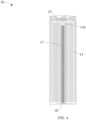
Fig. 4 is a sectional view taken along line A-A inFig. 1 , where a safety device is shown; and -
Fig. 5 is a vertical sectional view of the safety device of the battery shown inFig. 1 . -
- 10
- Battery
- 11
- Case
- 12
- Electrical terminal
- 13
- Cell
- 131
- Positive electrode plate
- 132
- Negative electrode plate
- 133
- Separator
- 134
- Winding cavity
- 14
- Insulating layer
- 15
- Positive electrode current collector
- 16
- Current cut-off device
- 17
- Safety device
- 171
- First electrode
- 172
- Gas generating material
- 173
- Second electrode
- 174
- Insulating layer
- 18
- Negative electrode current collector
- Specific embodiments of the present invention are now described in detail with reference to the accompanying drawings. Only preferred embodiments according to the present invention are described here, and those skilled in the art would conceive of other ways of implementation of the present invention on the basis of the preferred embodiments, which also fall within the scope of the present invention.
- The present invention provides a battery. In a preferred embodiment, the battery may be a lithium-ion battery. As shown in
Figs. 1 and2 , thebattery 10 is configured to have a generally cylindrical shape and comprises acase 11, anelectrical terminal 12, acell 13, an insulatinglayer 14, a positive electrodecurrent collector 15, a negative electrodecurrent collector 18, a current cut-offdevice 16, and other structures. Here, thecell 13 is a cylindrical structure composed of apositive electrode plate 131, anegative electrode plate 132 and an interposedseparator 133 that are stacked and wound in an arrangement manner shown inFig. 3 , and is filled with an electrolyte solution (not shown). It is to be understood that during preparation of thecell 13, a device such as a winding needle is used as an axis of winding. After the winding is completed, the winding needle is withdrawn from thecell 13. Thus, a windingcavity 134 is formed in thecell 13. - After preparation and forming, the
cell 13 is arranged in thecase 11. Thecase 11 may be made of a conductive material such as steel, and aluminium. In addition to providing supporting and accommodating functions, thecase 11 may also be electrically connected to thenegative electrode plate 132 of thecell 13 by means of the negative electrodecurrent collector 18 arranged at a lower end of thecell 13, thereby forming a negative terminal of thebattery 10 to be electrically connected to an external device. The positive electrodecurrent collector 15 is mounted at an upper end of thecell 13 and is electrically connected to thepositive electrode plate 131. Theelectrical terminal 12 is electrically connected to the positive electrodecurrent collector 15, forming a positive terminal of thebattery 10. In order to avoid an internal short-circuit, the insulatinglayer 14 is also arranged between thecase 11 and thecell 13 and between thecase 11 and theelectrical terminal 12 for insulating and isolating. - The current cut-off
device 16 is connected between theelectrical terminal 12 and the positive electrodecurrent collector 15. For example, the current cut-offdevice 16 may be kept in close contact with theelectrical terminal 12 through clamping and squeezing by thecase 11 to form an electrical connection, and may be connected to the positive electrodecurrent collector 15 by welding. The current cut-offdevice 16 isolates an internal space of thebattery 10 from an external environment, and the inner side of the current cut-off device is subject to an internal gas pressure of the battery and the outer side to an external ambient pressure. The current cut-offdevice 16 is provided with a weakened portion between the part connected to the positive electrodecurrent collector 15 and the part connected to theelectrical terminal 12. When a voltage and/or internal temperature of thebattery 10 rises to or even exceeds a safety threshold value due to, for example, overcharging, an increased gas pressure may be produced inside the battery, forming a great pressure difference between the inner and outer sides of the current cut-offdevice 16. When the pressure difference exceeds a structural strength of the weakened portion, the weakened portion is broken to cut off the electrical connection between theelectrical terminal 12 and the positive electrodecurrent collector 15, forming a break of circuit to prevent the temperature of thebattery 10 from continuing to rise. - In response to the increased gas pressure produced in the
battery 10 due to overcharging thereof, as shown inFigs. 4 and5 , thebattery 10 further comprises asafety device 17 having afirst electrode 171 and asecond electrode 173. Thefirst electrode 171 is electrically connected to one of the positive electrode and the negative electrode of thebattery 10, thesecond electrode 173 is electrically connected to the other one, and the first electrode and the second electrode are arranged spaced apart from each other. In this way, an electric field may be generated between thefirst electrode 171 and thesecond electrode 173. In other words, thefirst electrode 171 and thesecond electrode 173 form a structure similar to a capacitor. Further, thesafety device 17 also comprises agas generating material 172 arranged in the electric field formed between thefirst electrode 171 and thesecond electrode 173 and capable of generating an inert gas in response to that the voltage in the electric field rises to or exceeds a predetermined value. - Herein, the overcharging of the
battery 10 may be understood as thebattery 10 being charged at a constant current to the extent that its voltage exceeds a predetermined voltage value for a predetermined duration. A test standard for a battery used in a power tool is taken as an example: the battery is generally charged to 6 V to 7.5 V using a constant current of 2C and is kept at that voltage for 30 min after the voltage reaches a cut-off voltage. The battery is then in an overcharged state. - It is to be understood that as the
first electrode 171 and thesecond electrode 173 are respectively electrically connected to the positive electrode or the negative electrode of thebattery 10, the voltage of the electric field between the two is the voltage of thebattery 10. When thebattery 10 is overcharged, thegas generating material 172 of thesafety device 17 is also in an electric field environment with an excessive voltage, and generates an inert gas in response to this excessive voltage, resulting in an increase in the internal gas pressure of thebattery 10, leading to an increase in the pressure difference between the inner and outer sides of the current cut-offdevice 16. Further, when the pressure difference is increased beyond the structural strength of the weakened portion of the current cut-offdevice 16, its structure is destroyed, eventually leading to an internal break of circuit of thebattery 10. - Preferably, the
safety device 17 is configured as an elongated structure and accordingly may be arranged in the windingcavity 134 of thecell 13, so that the internal space of thebattery 10 can be used fully, making the battery compact in structure and avoiding an increase in size. Referring toFigs. 4 and5 , thefirst electrode 171 is configured as a cylindrical structure, the bottom of which is electrically connected to the negative electrodecurrent collector 18 at the lower end of thecell 13. For example, the two may be directly and fixedly connected together by welding. Thegas generating material 172 is filled inside the cylindrical structure. Thesecond electrode 173 is configured as a needle-like structure such as an elongated rod or needle, which may be fixedly connected to the positive electrodecurrent collector 15 by welding, so as to be electrically connected to the positive electrode of thebattery 10. The cylindrical structure is open towards an end portion of thesecond electrode 173. Thesecond electrode 173 is inserted into the cylindrical structure in an axial direction of the cylindrical structure and is partially buried in thegas generating material 172. In this way, thefirst electrode 171 and thesecond electrode 173 form a structure similar to a cylindrical capacitor, and thegas generating material 172 is arranged in the electric field between the first electrode and the second electrode. Preferably, thefirst electrode 171 and thesecond electrode 173 are coaxially arranged such that the voltage in the electric field is evenly distributed, and the voltage of thebattery 10 can thus be reflected more accurately. - The
first electrode 171 and thesecond electrode 173 may be made of a corrosion-resistant metal material such as stainless steel. The cylindrical structure for forming thefirst electrode 171 may have a diameter of 2 mm to 3 mm, a length of 5 mm or more, preferably greater than 8 mm, and a thickness of about 300 µm to 500 µm. The diameter and the length of the needle-like structure for forming thesecond electrode 173 may be designed to be suitable for being connected to the positive electrodecurrent collector 15 while being arranged in the cylindrical structure. As described above, in the illustrated embodiment, the end portion of the cylindrical structure facing towards thesecond electrode 173 is provided with an opening, which, in addition to facilitating the insertion of thesecond electrode 173 and facilitating filling the cylindrical structure with thegas generating material 172, may facilitate the escape of the gas generated by thegas generating material 172. It is to be understood that in other embodiments, the opening of the cylindrical structure may also be provided in another position, for example on the side, and that more than one opening may be provided. - Preferably, the
gas generating material 172 may comprise particles of an inorganic material, and the gas produced may be an inert gas that does not participate in combustion itself and cannot support combustion. The inert gas is inherently present in nature, which is non-toxic, non-hazardous, and safer. Moreover, the inert gas can use the pressure difference with the external environment to destroy the structure of the current cut-offdevice 16 to form a break of circuit, and can also reduce a concentration of oxygen inside thebattery 10 and a rate of oxidation reaction, to alleviate the problem of heat accumulation and thermal runaway caused by the oxidation reaction still existing in thecell 13 after thebattery 10 is subjected to a break of circuit, thereby inhibiting further temperature rise of thecell 13, and reducing the risk of combustion or explosion of thebattery 10. The particles of the inorganic material may be, for example, lithium carbonate particles, which can be decomposed in response to a high voltage and/or high temperature to produce carbon dioxide. Preferably, in order to increase the response speed and gas generation rate of the particles of the inorganic material, the particle size of the particles may be set to the micron level, for example, 10 µm to 20 µm. Thegas generating material 172 may have a mass of 10 mg to 200 mg depending on the different size of space in thecell 13. - Further, in order to enable the particles of the inorganic material in the
gas generating material 172 to react simultaneously to produce an inert gas, particles of a material capable of conducting electricity and heat, such as carbon black, may be doped therein to improve the electrical conductivity and thermal conductivity within the particles of the inorganic material, so that the voltage and the temperature can be uniformly distributed in thegas generating material 172. Preferably, in order to avoid a short circuit, at least the part of thesecond electrode 173 in contact with thegas generating material 172 is provided with an insulatinglayer 174. - The embodiments illustrated in the accompanying drawings have been described above. It is to be understood that in some further alternative embodiments, the specific structure and the arrangement of the safety device may be varied without departing from the inventive concept of the present application. For example, the safety device is not necessarily an elongated structure, but may be configured as a plate-shaped structure similar to a plate capacitor, and may be arranged at other locations in the internal space of the battery outside the winding cavity of the cell, as long as the internal space of the battery is allowable.
- According to the technical solution of the present invention, as the overcharge additive is concentrated in the safety device, the amount of overcharge additive that reacts when the battery is overcharged can be increased, the gas generation rate can be increased, and the gas may escape directly into an internal space of the battery, thereby saving time for migration from the cell and increasing the reaction rate. In addition, as there is no need to disperse the overcharge additive in the electrode plates of the cell by means of doping, the energy density and the power density of electrode plates are increased, while the risk of introducing metallic foreign bodies can be reduced, with less negative impact on the design and the electrochemical performance of the cell. In one embodiment, the positive electrode plate of the cell is not doped with lithium carbonate.
- The foregoing description of the multiple embodiments of the present invention is provided for descriptive purposes to a person of ordinary skill in the related art. It is not intended to exclude or limit the present invention to a single disclosed embodiment. As described above, various substitutions and variations of the present invention will be apparent to those of ordinary skill in the art. Therefore, while some alternative embodiments are specifically described, other embodiments will be apparent or relatively readily developed by those of ordinary skill in the art. The present invention is intended to include all substitutions, modifications and variations of the present invention as described herein, and the other embodiments that fall within the spirit and scope of the present invention as described above.
Claims (10)
- A battery, characterized by comprising:a case (11);a cell (13), the cell (13) being packaged in the case (11);an electrical terminal (12), the electrical terminal (12) being located at one end of the case (11) and electrically connected to the cell (13);a safety device (17), the safety device (17) comprising:a first electrode (171), wherein the first electrode (171) is electrically connected to one of a positive electrode and a negative electrode of the cell;a second electrode (173), wherein the second electrode (173) is electrically connected to the other one of the positive electrode and the negative electrode, the first electrode (171) and the second electrode (173) are arranged spaced apart from each other, and an electric field is formed between the first electrode and the second electrode; anda gas generating material (172), wherein the gas generating material (172) is provided in the electric field and capable of generating an inert gas when a voltage in the electric field reaches or exceeds a predetermined threshold value; anda current cut-off device (16), the current cut-off device (16) being electrically connected between the cell (13) and the electrical terminal (12) and capable of causing a brake of circuit in response to a pressure difference between the inside of the battery and an external environment caused by the inert gas generated by the safety device (17).
- The battery according to claim 1, characterized in that the battery is a lithium-ion battery, the cell (13) is composed of a positive electrode plate (131), a separator (133) and a negative electrode plate (132) that are stacked and wound, and has an internal winding cavity (134), the safety device (17) is configured to have an elongated shape and arranged in the winding cavity (134), and preferably, the positive electrode plate (131) is not doped with lithium carbonate.
- The battery according to claim 2, characterized in that one of the first electrode (171) and the second electrode (173) is configured as a cylinder in which the gas generating material (172) is filled, and the other one is configured as a needle-like structure which extends at least partially into the cylinder in an axial direction of the cylinder and is buried in the gas generating material (172).
- The battery according to claim 3, characterized in that the gas generating material (172) is doped with conductive particles, and at least a part of the needle-like structure that is in contact with the gas generating material (172) is provided with an insulating layer (174).
- The battery according to claim 4, characterized in that the conductive particles are carbon black.
- The battery according to any one of claims 3 to 5, characterized in that the cylinder is provided with at least one opening through which an internal space of the cylinder is capable of communicating with the winding cavity (134).
- The battery according to claim 6, characterized in that at least one of the at least one opening is provided at an end portion of the cylinder that faces towards the needle-like structure.
- The battery according to any one of claims 1 to 7, characterized in that the first electrode (171) and the second electrode (173) are made of a corrosion-resistant metal material, and preferably of stainless steel.
- The battery according to any one of claims 1 to 8, characterized in that the gas generating material (172) comprises particles of an inorganic material that have a micron-order size, the inorganic material preferably comprises lithium carbonate, and the size is preferably 10 µm to 20 µm.
- The battery according to claim 9, characterized in that the gas generating material (172) has a mass of 10 mg to 200 mg.
Applications Claiming Priority (1)
| Application Number | Priority Date | Filing Date | Title |
|---|---|---|---|
| CN202210062284.1A CN116505055A (en) | 2022-01-19 | 2022-01-19 | a battery |
Publications (3)
| Publication Number | Publication Date |
|---|---|
| EP4216365A1 true EP4216365A1 (en) | 2023-07-26 |
| EP4216365C0 EP4216365C0 (en) | 2025-05-14 |
| EP4216365B1 EP4216365B1 (en) | 2025-05-14 |
Family
ID=85017685
Family Applications (1)
| Application Number | Title | Priority Date | Filing Date |
|---|---|---|---|
| EP23152391.1A Active EP4216365B1 (en) | 2022-01-19 | 2023-01-19 | Battery |
Country Status (4)
| Country | Link |
|---|---|
| US (1) | US12700651B2 (en) |
| EP (1) | EP4216365B1 (en) |
| CN (1) | CN116505055A (en) |
| AU (1) | AU2023200246A1 (en) |
Citations (3)
| Publication number | Priority date | Publication date | Assignee | Title |
|---|---|---|---|---|
| EP1710858A1 (en) * | 2005-03-30 | 2006-10-11 | Samsung SDI Co., Ltd. | Cylindrical lithium ion secondary battery |
| US20180159109A1 (en) * | 2016-12-07 | 2018-06-07 | Toyota Jidosha Kabushiki Kaisha | Lithium ion secondary battery |
| EP3544085A1 (en) * | 2018-01-30 | 2019-09-25 | Wang Guocheng | Battery connecting device and battery pack having same |
Family Cites Families (2)
| Publication number | Priority date | Publication date | Assignee | Title |
|---|---|---|---|---|
| KR102264906B1 (en) * | 2017-11-23 | 2021-06-14 | 주식회사 엘지에너지솔루션 | Battery module with improved safety, battery pack comprising the battery module and vehicle comprising the same |
| KR102565019B1 (en) * | 2018-06-04 | 2023-08-08 | 주식회사 엘지에너지솔루션 | Cylindrical Secondary Battery Having Adhesive Part comprising Gas Generation Material |
-
2022
- 2022-01-19 CN CN202210062284.1A patent/CN116505055A/en active Pending
-
2023
- 2023-01-16 US US18/154,992 patent/US12700651B2/en active Active
- 2023-01-18 AU AU2023200246A patent/AU2023200246A1/en active Pending
- 2023-01-19 EP EP23152391.1A patent/EP4216365B1/en active Active
Patent Citations (3)
| Publication number | Priority date | Publication date | Assignee | Title |
|---|---|---|---|---|
| EP1710858A1 (en) * | 2005-03-30 | 2006-10-11 | Samsung SDI Co., Ltd. | Cylindrical lithium ion secondary battery |
| US20180159109A1 (en) * | 2016-12-07 | 2018-06-07 | Toyota Jidosha Kabushiki Kaisha | Lithium ion secondary battery |
| EP3544085A1 (en) * | 2018-01-30 | 2019-09-25 | Wang Guocheng | Battery connecting device and battery pack having same |
Also Published As
| Publication number | Publication date |
|---|---|
| AU2023200246A1 (en) | 2023-08-03 |
| EP4216365C0 (en) | 2025-05-14 |
| US20230231291A1 (en) | 2023-07-20 |
| CN116505055A (en) | 2023-07-28 |
| US12700651B2 (en) | 2026-08-04 |
| EP4216365B1 (en) | 2025-05-14 |
Similar Documents
| Publication | Publication Date | Title |
|---|---|---|
| KR100477750B1 (en) | Electorde assembly for lithium ion cell and lithium ion cell using the same | |
| CN115693047B (en) | End cover components, battery cells, batteries and electrical devices | |
| KR20120039181A (en) | Cap assembly of novel structure and cylindrical battery employed with the same | |
| CN1964126A (en) | Lithium ion secondary battery | |
| EP4383434A1 (en) | Battery and electric apparatus | |
| US20250210762A1 (en) | Battery cell, battery, and electrical apparatus | |
| US5747188A (en) | Battery with improved safety during mechanical abuse | |
| JP4515405B2 (en) | Cylindrical lithium secondary battery and manufacturing method thereof | |
| CN103392257A (en) | Lithium-ion battery | |
| JP7830617B2 (en) | Jig for safety evaluation of secondary batteries | |
| KR101608694B1 (en) | A Safeguard Apparatus Preventing Overcharge for A Secondary Battery | |
| CN107482140B (en) | Battery cover plate of external double-insurance protection device | |
| JPH10255757A (en) | Lithium secondary battery | |
| EP4216365B1 (en) | Battery | |
| CN212412135U (en) | Battery cover plate assembly and single battery | |
| CN218769788U (en) | Cylindrical battery and cylindrical battery module | |
| JP4826245B2 (en) | Winding type secondary battery | |
| CN110690404B (en) | Heavy-current power-off device and lithium ion battery | |
| JPH10321260A (en) | Lithium ion secondary battery | |
| CN116505213A (en) | A high-safety lithium power battery with CID and external PTC | |
| CN203119024U (en) | External overcurrent protection device for lithium battery | |
| CN201038223Y (en) | Secondary battery tab and secondary battery comprising same | |
| CN217823186U (en) | Battery with improved battery capacity | |
| CN219393322U (en) | Fusing device with arc extinguishing device | |
| JP3250530U (en) | Safe cylindrical battery |
Legal Events
| Date | Code | Title | Description |
|---|---|---|---|
| PUAI | Public reference made under article 153(3) epc to a published international application that has entered the european phase |
Free format text: ORIGINAL CODE: 0009012 |
|
| STAA | Information on the status of an ep patent application or granted ep patent |
Free format text: STATUS: THE APPLICATION HAS BEEN PUBLISHED |
|
| AK | Designated contracting states |
Kind code of ref document: A1 Designated state(s): AL AT BE BG CH CY CZ DE DK EE ES FI FR GB GR HR HU IE IS IT LI LT LU LV MC ME MK MT NL NO PL PT RO RS SE SI SK SM TR |
|
| STAA | Information on the status of an ep patent application or granted ep patent |
Free format text: STATUS: REQUEST FOR EXAMINATION WAS MADE |
|
| 17P | Request for examination filed |
Effective date: 20240123 |
|
| RBV | Designated contracting states (corrected) |
Designated state(s): AL AT BE BG CH CY CZ DE DK EE ES FI FR GB GR HR HU IE IS IT LI LT LU LV MC ME MK MT NL NO PL PT RO RS SE SI SK SM TR |
|
| GRAP | Despatch of communication of intention to grant a patent |
Free format text: ORIGINAL CODE: EPIDOSNIGR1 |
|
| STAA | Information on the status of an ep patent application or granted ep patent |
Free format text: STATUS: GRANT OF PATENT IS INTENDED |
|
| INTG | Intention to grant announced |
Effective date: 20250217 |
|
| GRAS | Grant fee paid |
Free format text: ORIGINAL CODE: EPIDOSNIGR3 |
|
| GRAA | (expected) grant |
Free format text: ORIGINAL CODE: 0009210 |
|
| STAA | Information on the status of an ep patent application or granted ep patent |
Free format text: STATUS: THE PATENT HAS BEEN GRANTED |
|
| AK | Designated contracting states |
Kind code of ref document: B1 Designated state(s): AL AT BE BG CH CY CZ DE DK EE ES FI FR GB GR HR HU IE IS IT LI LT LU LV MC ME MK MT NL NO PL PT RO RS SE SI SK SM TR |
|
| REG | Reference to a national code |
Ref country code: GB Ref legal event code: FG4D |
|
| REG | Reference to a national code |
Ref country code: CH Ref legal event code: EP |
|
| REG | Reference to a national code |
Ref country code: DE Ref legal event code: R096 Ref document number: 602023003401 Country of ref document: DE |
|
| REG | Reference to a national code |
Ref country code: IE Ref legal event code: FG4D |
|
| U01 | Request for unitary effect filed |
Effective date: 20250604 |
|
| U07 | Unitary effect registered |
Designated state(s): AT BE BG DE DK EE FI FR IT LT LU LV MT NL PT RO SE SI Effective date: 20250613 |
|
| PG25 | Lapsed in a contracting state [announced via postgrant information from national office to epo] |
Ref country code: ES Free format text: LAPSE BECAUSE OF FAILURE TO SUBMIT A TRANSLATION OF THE DESCRIPTION OR TO PAY THE FEE WITHIN THE PRESCRIBED TIME-LIMIT Effective date: 20250514 |
|
| PG25 | Lapsed in a contracting state [announced via postgrant information from national office to epo] |
Ref country code: NO Free format text: LAPSE BECAUSE OF FAILURE TO SUBMIT A TRANSLATION OF THE DESCRIPTION OR TO PAY THE FEE WITHIN THE PRESCRIBED TIME-LIMIT Effective date: 20250814 Ref country code: GR Free format text: LAPSE BECAUSE OF FAILURE TO SUBMIT A TRANSLATION OF THE DESCRIPTION OR TO PAY THE FEE WITHIN THE PRESCRIBED TIME-LIMIT Effective date: 20250815 |
|
| PG25 | Lapsed in a contracting state [announced via postgrant information from national office to epo] |
Ref country code: PL Free format text: LAPSE BECAUSE OF FAILURE TO SUBMIT A TRANSLATION OF THE DESCRIPTION OR TO PAY THE FEE WITHIN THE PRESCRIBED TIME-LIMIT Effective date: 20250514 |
|
| PG25 | Lapsed in a contracting state [announced via postgrant information from national office to epo] |
Ref country code: HR Free format text: LAPSE BECAUSE OF FAILURE TO SUBMIT A TRANSLATION OF THE DESCRIPTION OR TO PAY THE FEE WITHIN THE PRESCRIBED TIME-LIMIT Effective date: 20250514 |
|
| PG25 | Lapsed in a contracting state [announced via postgrant information from national office to epo] |
Ref country code: RS Free format text: LAPSE BECAUSE OF FAILURE TO SUBMIT A TRANSLATION OF THE DESCRIPTION OR TO PAY THE FEE WITHIN THE PRESCRIBED TIME-LIMIT Effective date: 20250814 |
|
| PG25 | Lapsed in a contracting state [announced via postgrant information from national office to epo] |
Ref country code: IS Free format text: LAPSE BECAUSE OF FAILURE TO SUBMIT A TRANSLATION OF THE DESCRIPTION OR TO PAY THE FEE WITHIN THE PRESCRIBED TIME-LIMIT Effective date: 20250914 |
|
| PG25 | Lapsed in a contracting state [announced via postgrant information from national office to epo] |
Ref country code: SM Free format text: LAPSE BECAUSE OF FAILURE TO SUBMIT A TRANSLATION OF THE DESCRIPTION OR TO PAY THE FEE WITHIN THE PRESCRIBED TIME-LIMIT Effective date: 20250514 |
|
| PG25 | Lapsed in a contracting state [announced via postgrant information from national office to epo] |
Ref country code: CZ Free format text: LAPSE BECAUSE OF FAILURE TO SUBMIT A TRANSLATION OF THE DESCRIPTION OR TO PAY THE FEE WITHIN THE PRESCRIBED TIME-LIMIT Effective date: 20250514 |
|
| PG25 | Lapsed in a contracting state [announced via postgrant information from national office to epo] |
Ref country code: SK Free format text: LAPSE BECAUSE OF FAILURE TO SUBMIT A TRANSLATION OF THE DESCRIPTION OR TO PAY THE FEE WITHIN THE PRESCRIBED TIME-LIMIT Effective date: 20250514 |
|
| U20 | Renewal fee for the european patent with unitary effect paid |
Year of fee payment: 4 Effective date: 20260127 |
|
| PLBE | No opposition filed within time limit |
Free format text: ORIGINAL CODE: 0009261 |
|
| STAA | Information on the status of an ep patent application or granted ep patent |
Free format text: STATUS: NO OPPOSITION FILED WITHIN TIME LIMIT |
|
| REG | Reference to a national code |
Ref country code: CH Ref legal event code: L10 Free format text: ST27 STATUS EVENT CODE: U-0-0-L10-L00 (AS PROVIDED BY THE NATIONAL OFFICE) Effective date: 20260325 |
|
| 26N | No opposition filed |
Effective date: 20260217 |