EP4216329A1 - Method for manufacturing electrode assembly and apparatus for manufacturing same - Google Patents
Method for manufacturing electrode assembly and apparatus for manufacturing same Download PDFInfo
- Publication number
- EP4216329A1 EP4216329A1 EP22876866.9A EP22876866A EP4216329A1 EP 4216329 A1 EP4216329 A1 EP 4216329A1 EP 22876866 A EP22876866 A EP 22876866A EP 4216329 A1 EP4216329 A1 EP 4216329A1
- Authority
- EP
- European Patent Office
- Prior art keywords
- unit cells
- electrode assembly
- separation film
- manufacturing
- assembly according
- Prior art date
- Legal status (The legal status is an assumption and is not a legal conclusion. Google has not performed a legal analysis and makes no representation as to the accuracy of the status listed.)
- Pending
Links
Images
Classifications
-
- H—ELECTRICITY
- H01—ELECTRIC ELEMENTS
- H01M—PROCESSES OR MEANS, e.g. BATTERIES, FOR THE DIRECT CONVERSION OF CHEMICAL ENERGY INTO ELECTRICAL ENERGY
- H01M10/00—Secondary cells; Manufacture thereof
- H01M10/04—Construction or manufacture in general
- H01M10/0431—Cells with wound or folded electrodes
-
- H—ELECTRICITY
- H01—ELECTRIC ELEMENTS
- H01M—PROCESSES OR MEANS, e.g. BATTERIES, FOR THE DIRECT CONVERSION OF CHEMICAL ENERGY INTO ELECTRICAL ENERGY
- H01M10/00—Secondary cells; Manufacture thereof
- H01M10/04—Construction or manufacture in general
- H01M10/0459—Cells or batteries with folded separator between plate-like electrodes
-
- H—ELECTRICITY
- H01—ELECTRIC ELEMENTS
- H01M—PROCESSES OR MEANS, e.g. BATTERIES, FOR THE DIRECT CONVERSION OF CHEMICAL ENERGY INTO ELECTRICAL ENERGY
- H01M10/00—Secondary cells; Manufacture thereof
- H01M10/04—Construction or manufacture in general
- H01M10/0404—Machines for assembling batteries
-
- H—ELECTRICITY
- H01—ELECTRIC ELEMENTS
- H01M—PROCESSES OR MEANS, e.g. BATTERIES, FOR THE DIRECT CONVERSION OF CHEMICAL ENERGY INTO ELECTRICAL ENERGY
- H01M10/00—Secondary cells; Manufacture thereof
- H01M10/04—Construction or manufacture in general
- H01M10/0404—Machines for assembling batteries
- H01M10/0409—Machines for assembling batteries for cells with wound electrodes
-
- H—ELECTRICITY
- H01—ELECTRIC ELEMENTS
- H01M—PROCESSES OR MEANS, e.g. BATTERIES, FOR THE DIRECT CONVERSION OF CHEMICAL ENERGY INTO ELECTRICAL ENERGY
- H01M10/00—Secondary cells; Manufacture thereof
- H01M10/04—Construction or manufacture in general
- H01M10/0413—Large-sized flat cells or batteries for motive or stationary systems with plate-like electrodes
-
- H—ELECTRICITY
- H01—ELECTRIC ELEMENTS
- H01M—PROCESSES OR MEANS, e.g. BATTERIES, FOR THE DIRECT CONVERSION OF CHEMICAL ENERGY INTO ELECTRICAL ENERGY
- H01M10/00—Secondary cells; Manufacture thereof
- H01M10/04—Construction or manufacture in general
- H01M10/0436—Small-sized flat cells or batteries for portable equipment
-
- H—ELECTRICITY
- H01—ELECTRIC ELEMENTS
- H01M—PROCESSES OR MEANS, e.g. BATTERIES, FOR THE DIRECT CONVERSION OF CHEMICAL ENERGY INTO ELECTRICAL ENERGY
- H01M10/00—Secondary cells; Manufacture thereof
- H01M10/05—Accumulators with non-aqueous electrolyte
- H01M10/052—Li-accumulators
-
- H—ELECTRICITY
- H01—ELECTRIC ELEMENTS
- H01M—PROCESSES OR MEANS, e.g. BATTERIES, FOR THE DIRECT CONVERSION OF CHEMICAL ENERGY INTO ELECTRICAL ENERGY
- H01M10/00—Secondary cells; Manufacture thereof
- H01M10/05—Accumulators with non-aqueous electrolyte
- H01M10/052—Li-accumulators
- H01M10/0525—Rocking-chair batteries, i.e. batteries with lithium insertion or intercalation in both electrodes; Lithium-ion batteries
-
- H—ELECTRICITY
- H01—ELECTRIC ELEMENTS
- H01M—PROCESSES OR MEANS, e.g. BATTERIES, FOR THE DIRECT CONVERSION OF CHEMICAL ENERGY INTO ELECTRICAL ENERGY
- H01M10/00—Secondary cells; Manufacture thereof
- H01M10/05—Accumulators with non-aqueous electrolyte
- H01M10/058—Construction or manufacture
- H01M10/0587—Construction or manufacture of accumulators having only wound construction elements, i.e. wound positive electrodes, wound negative electrodes and wound separators
-
- H—ELECTRICITY
- H01—ELECTRIC ELEMENTS
- H01M—PROCESSES OR MEANS, e.g. BATTERIES, FOR THE DIRECT CONVERSION OF CHEMICAL ENERGY INTO ELECTRICAL ENERGY
- H01M10/00—Secondary cells; Manufacture thereof
- H01M10/05—Accumulators with non-aqueous electrolyte
- H01M10/058—Construction or manufacture
- H01M10/0583—Construction or manufacture of accumulators with folded construction elements except wound ones, i.e. folded positive or negative electrodes or separators, e.g. with "Z"-shaped electrodes or separators
-
- Y—GENERAL TAGGING OF NEW TECHNOLOGICAL DEVELOPMENTS; GENERAL TAGGING OF CROSS-SECTIONAL TECHNOLOGIES SPANNING OVER SEVERAL SECTIONS OF THE IPC; TECHNICAL SUBJECTS COVERED BY FORMER USPC CROSS-REFERENCE ART COLLECTIONS [XRACs] AND DIGESTS
- Y02—TECHNOLOGIES OR APPLICATIONS FOR MITIGATION OR ADAPTATION AGAINST CLIMATE CHANGE
- Y02E—REDUCTION OF GREENHOUSE GAS [GHG] EMISSIONS, RELATED TO ENERGY GENERATION, TRANSMISSION OR DISTRIBUTION
- Y02E60/00—Enabling technologies; Technologies with a potential or indirect contribution to GHG emissions mitigation
- Y02E60/10—Energy storage using batteries
-
- Y—GENERAL TAGGING OF NEW TECHNOLOGICAL DEVELOPMENTS; GENERAL TAGGING OF CROSS-SECTIONAL TECHNOLOGIES SPANNING OVER SEVERAL SECTIONS OF THE IPC; TECHNICAL SUBJECTS COVERED BY FORMER USPC CROSS-REFERENCE ART COLLECTIONS [XRACs] AND DIGESTS
- Y02—TECHNOLOGIES OR APPLICATIONS FOR MITIGATION OR ADAPTATION AGAINST CLIMATE CHANGE
- Y02P—CLIMATE CHANGE MITIGATION TECHNOLOGIES IN THE PRODUCTION OR PROCESSING OF GOODS
- Y02P70/00—Climate change mitigation technologies in the production process for final industrial or consumer products
- Y02P70/50—Manufacturing or production processes characterised by the final manufactured product
Definitions
- the present disclosure relates to a method of manufacturing an electrode assembly and a manufacturing apparatus thereof.
- a secondary battery is a representative example of an electrochemical device that utilizes such electrochemical energy, and the range of use thereof tends to be gradually expanding.
- secondary batteries In recent years, as mobile devices, such as portable computers, portable phones, and cameras, have been increasingly developed, the demand for secondary batteries has also sharply increased as an energy source for the mobile devices.
- secondary batteries is a lithium secondary battery exhibiting a high energy density and a high voltage, a long cycle lifespan, and a low self-discharge rate, in which much research has been carried out and which is now commercialized and widely used.
- This lithium secondary battery has a structure in which an electrode assembly is built into a secondary battery case, and the electrode assembly is structurally classified into a jelly roll-type electrode assembly manufactured by winding a cathode sheet, an anode sheet, and a separation film, a stacked electrode assembly that stacks a unit cathode, a unit anode, and a separator, a stack/folding type electrode assembly that winds unit cells such as bi-cells, full-cells or mono-cell with a separator film, and a stacked/laminated type electrode assembly that laminates the unit cells.
- a jelly roll-type electrode assembly manufactured by winding a cathode sheet, an anode sheet, and a separation film
- a stacked electrode assembly that stacks a unit cathode, a unit anode, and a separator
- a stack/folding type electrode assembly that winds unit cells such as bi-cells, full-cells or mono-cell with a separator film
- the stack/folding type electrode assembly has a problem that as the unit cell is mounted on the separation film and then simply wound, a non-bonded region between the folding surface and the unit cell is increased, the interfacial resistance in the non-bonded region is increased, and thus lithium is deposited.
- the electrode included in the unit cells has a flat portion in which the thickness of the active material layer is constant and an inclined portion whose thickness gradually decreases from both ends thereof, wherein the non-bonded region is more pronounced at the inclined portion.
- the lithium deposited therefrom threatens the safety of the secondary battery, which causes a problem that cycle characteristics are remarkably deteriorated.
- the present disclosure is designed to solve the above-mentioned problems, and an object of the present disclosure is to provide a method of manufacturing an electrode assembly and a manufacturing apparatus thereof that can suppress lithium deposition at both ends where the electrode assembly tabs are formed, thus improving the safety and cycle characteristics of a secondary battery
- a method of manufacturing an electrode assembly in which unit cells are wound with a separation film comprising the steps of:
- the unit cells may be mounted on the upper surface of the separation film, so that the electrode tabs having the same polarity are located upward and downward at the same position after winding.
- step (b) may be performed by heating or hot air, and the heat treatment of step (b) may be performed at 50°C to 200°C.
- the electrode included in the unit cells has a flat portion where the thickness of the active material layer is constant and an inclined portion where the thickness of the active material layer decreases from both ends of the flat portion, and one end and the other end where tabs of the unit cells are formed may include a region corresponding to the inclined portion.
- the winding speed of step (c) may be 5 ppm to 30 ppm.
- the heat treatment in step (b) and the winding in step (c) may be performed continuously, and thus, the heat treatment time is affected by the winding speed.
- the electrode assembly may include a single-sided electrode in which an active material layer is formed only on the inner side of the electrode located at the outermost portion in a wound state.
- Each of the unit cells may be a bi-cell, a full-cell, or a mono-cell.
- an apparatus of manufacturing an electrode assembly in which unit cells are wound with a separation film comprising:
- the heater may be of a heating type or a hot air type.
- the heater may be formed in a portion wholly covered the unit cells which are mounted on the upper surface of the separation film.
- the winder may be located on one side of the heater.
- a method of manufacturing an electrode assembly in which unit cells are wound with a separation film comprising the steps of:
- an apparatus of manufacturing an electrode assembly in which unit cells are wound with a separation film comprising:
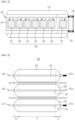
- Fig. 1 schematically shows an electrode manufacturing apparatus for a secondary battery according to an embodiment of the present disclosure.
- an electrode assembly manufacturing apparatus 100 for a secondary battery includes a winder 130 that winds an array body 120 in which unit cells 108: 101, 102, 103, 104, 105, 106 and 107 are mounted on the upper surface of a separation film 110, and heater 140 that are located at the upper and lower portions in the longitudinal direction of the separation film 110 parallel to the winding direction of the array body 120 and heat-treats one end and the other end where tabs of the unit cells are formed, and the separation film 110 corresponding thereto.
- the electrode assembly of the present disclosure is manufactured by arranging a plurality of unit cells 108 on the separation film 110 to prepare the array body 120.
- the unit cells 108 are wound and then arranged so that the electrode tabs having the same polarity are located upward and downward at the same position.
- Each of the unit cells 108 may be a bi-cell in which electrodes having the same polarity are located at both ends, a full-cell in which electrodes having different polarity are located at both ends, or a mono-cell including one electrode.
- the bi-cell may have a structure of anode/separator/cathode/separator/anode
- the full-cell may have a structure of anode/separator/cathode
- the mono-cell may have a structure in which any one electrode of a cathode or an anode and a separator are stacked.
- the unit cells 108 are wound and then should be arranged so as to have a stacked structure in which cathode and anode are alternately arranged.
- the electrodes included in the unit cells 108 are configured such that an inclination is generated at one end and the other end where tabs are formed due to application of the electrode active material slurry during the manufacturing process of the electrode.
- FIG. 2 schematically shows a side view of the unit cell of the present disclosure.
- the unit cell 200 is composed of a plurality of electrodes 210, 220 and 230.
- Fig. 2 shows a bi-cell consisting of three electrodes 210, 220 and 230, but is not so limited thereto.
- the electrodes 210, 220 and 230 have a structure in which active material layers 212, 222 and 232 are formed on current collectors 211, 221 and 231, respectively, and electrode tabs 211a, 221a and 231a are formed on one side of the current collectors 211, 221 and 231, respectively.
- the active material layers 212, 222 and 232 have a flat portion P where the thickness of active material layers 212, 222 and 232 are constant, and inclined portions L 1 and L 2 where the thickness of the active material layers 212, 222 and 232 decreases from both ends of the flat portion P.
- the active material layer has an inclined portion L 1 on one end side of the tab in the direction in which the tab is formed and an inclined portion L 2 on the other end side corresponding thereto.
- the active material layers of the electrodes 210, 220 and 230 forming the unit cell 200 have the inclined portions L 1 and L 2 , so that when the unit cell 200 is wound with a separation film, the inclined portion L 1 of one end where a tab is formed and the inclined portion L 2 of the other end corresponding thereto are spaced apart from the separation film to generate a space and not bonded, and thus, the deposition of lithium often occurs in the region.
- a process is performed in which the array body 120 in which the unit cells 108 are mounted on the separation film 110 is heat-treated together with one end and the other end in which the tabs are formed in the unit cells 108, and the separation film 110 corresponding thereto.
- one end and the other end where tabs of the unit cells 108 subjected to heat treatment are formed may be regions S 1 and S 2 including regions corresponding to the inclined portions of the electrodes.
- the heat treatment is performed by heaters 140 located at the upper and lower portions in the longitudinal direction of the separation film 110, wherein the heat treatment may be performed by heating or hot air, and therefore, the heater 140 may be a heating type or hot air type device.
- the heat treatment may be performed at 50°C to 200°C.
- the bonding effect intended by the present disclosure cannot be sufficiently obtained, and if the heat treatment is performed at too high a temperature, deformation of the active material layer and deformation of the separation film may be occurred, which is not preferable.
- the unit cells 108 are wound with the separation film 110.
- the heat treatment time may be affected by the winding speed performed after the heat treatment.
- the winder 130 for winding the array body 120 may be located on one side of the heater 140, whereby the heat treatment of step (b) and the winding of step (c) may be performed continuously. Therefore, the heat treatment time can be affected by the winding speed.
- the winding speed of step (c) may be 5ppm to 30ppm.
- the heater 140 for performing the heat treatment is not limited in size, and the unit cells 108 may be formed in a portion mounted on the upper surface of the separation film 110, so that the unit cells 108 can be sufficiently heat-treated.
- the heat treatment time of the unit cell may be 3 seconds to 20 seconds.
- the electrode assembly manufactured in this way may be a single-sided electrode in which an active material layer is formed only on the inner side of the electrode located at the outermost portion in a wound state.
- the electrode facing the separation film 110 in the two unit cells 106 and 107 at the winding end point of Fig. 1 may be a single-sided electrode.
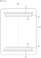
- FIG. 3 a cross-sectional view of the electrode assembly in a wound state is shown in Fig. 3 .
- the electrode assembly 300 has a structure in which unit cells are wound with a separation film 310.
- respective electrodes 320 and 330 included in the unit cells 106 and 107 present at the outermost portion is a single-sided electrode in which active material layers 322 and 332 are respectively formed only on the inner side of an electrode assembly 300 on current collectors 321 and 331.
- the electrode 320 located on the upper portions is formed with the active material layer 321 only on the lower surface of the current collector 321, and the electrode 330 located at the lower portion is formed with an active material layer 332 only on the upper surface of the current collector 331.
- the electrodes located at the outermost portion are single-sided electrodes, there is no waste of the active material layer, and the overall thickness of the electrode assembly is reduced, which is thus more preferable.
- a non-bonded region between the separation film and the unit cells can be minimized and thus, the deposition of lithium can be minimized, thereby improving the safety and cycle characteristics of a secondary battery including the same.
Landscapes
- Engineering & Computer Science (AREA)
- Chemical & Material Sciences (AREA)
- Manufacturing & Machinery (AREA)
- Chemical Kinetics & Catalysis (AREA)
- Electrochemistry (AREA)
- General Chemical & Material Sciences (AREA)
- Materials Engineering (AREA)
- Secondary Cells (AREA)
- Battery Electrode And Active Subsutance (AREA)
- Connection Of Batteries Or Terminals (AREA)
Abstract
Description
- This application claims the benefit of
Korean Patent Application No. 10-2021-0128689 filed on September 29, 2021 - The present disclosure relates to a method of manufacturing an electrode assembly and a manufacturing apparatus thereof.
- Due to the rapid increase in the use of fossil fuels, the demand for the use of alternative energy or clean energy is increasing, and as part thereof, the fields that are being studied most actively are the fields of power generation and power storage using electrochemistry.
- At present, a secondary battery is a representative example of an electrochemical device that utilizes such electrochemical energy, and the range of use thereof tends to be gradually expanding.
- In recent years, as mobile devices, such as portable computers, portable phones, and cameras, have been increasingly developed, the demand for secondary batteries has also sharply increased as an energy source for the mobile devices. Among such secondary batteries is a lithium secondary battery exhibiting a high energy density and a high voltage, a long cycle lifespan, and a low self-discharge rate, in which much research has been carried out and which is now commercialized and widely used.
- In addition, as interest in environmental issues grows, studies are frequently conducted on an electric vehicle, a hybrid electric vehicle, etc. which can replace a vehicle using fossil fuels such as a gasoline vehicle and a diesel vehicle, which are one of the main causes of air pollution. Although a nickel metal hydride secondary battery is mainly used as a power source for the electric vehicle and the hybrid electric vehicle, research on the use of a lithium secondary battery having high energy density and discharge voltage is actively being conducted, a part of which are in the commercialization stage.
- This lithium secondary battery has a structure in which an electrode assembly is built into a secondary battery case, and the electrode assembly is structurally classified into a jelly roll-type electrode assembly manufactured by winding a cathode sheet, an anode sheet, and a separation film, a stacked electrode assembly that stacks a unit cathode, a unit anode, and a separator, a stack/folding type electrode assembly that winds unit cells such as bi-cells, full-cells or mono-cell with a separator film, and a stacked/laminated type electrode assembly that laminates the unit cells.
- At this time, during the folding process of winding the unit cells with a separation film, the stack/folding type electrode assembly has a problem that as the unit cell is mounted on the separation film and then simply wound, a non-bonded region between the folding surface and the unit cell is increased, the interfacial resistance in the non-bonded region is increased, and thus lithium is deposited.
- Particularly, the electrode included in the unit cells has a flat portion in which the thickness of the active material layer is constant and an inclined portion whose thickness gradually decreases from both ends thereof, wherein the non-bonded region is more pronounced at the inclined portion.
- Therefore, the lithium deposited therefrom threatens the safety of the secondary battery, which causes a problem that cycle characteristics are remarkably deteriorated.
- Therefore, there is an urgent need to develop a technique for manufacturing an electrode assembly for a secondary battery that can solve these problems.
- The present disclosure is designed to solve the above-mentioned problems, and an object of the present disclosure is to provide a method of manufacturing an electrode assembly and a manufacturing apparatus thereof that can suppress lithium deposition at both ends where the electrode assembly tabs are formed, thus improving the safety and cycle characteristics of a secondary battery
- Terms or words used in the present specification and claims should not be construed as limited to ordinary or dictionary terms, and the present disclosure should be construed with meanings and concepts that are consistent with the technical idea of the present disclosure based on the principle that the inventors may appropriately define concepts of the terms to appropriately describe their own disclosure in the best way.
- Hereinafter, according to one embodiment of the present disclosure, there is provided a method of manufacturing an electrode assembly in which unit cells are wound with a separation film, the method comprising the steps of:
- (a) mounting unit cells on the upper surface of the separation film to prepare an array body;
- (b) heat-treating one end of each of the unit cells where tabs of the unit cells are formed, another end of each of the unit cells, and the separation film positioned at a corresponding thereto, which are positioned in the upper and lower portions of a direction parallel to a longitudinal direction of the separation film and parallel to a winding direction of the array body; and
- (c) winding the heat-treated unit cells with the separation film.
- In step (a), the unit cells may be mounted on the upper surface of the separation film, so that the electrode tabs having the same polarity are located upward and downward at the same position after winding.
- Further, the heat treatment of step (b) may be performed by heating or hot air, and the heat treatment of step (b) may be performed at 50°C to 200°C.
- When specifically considering the region where the heat treatment is performed, the electrode included in the unit cells has a flat portion where the thickness of the active material layer is constant and an inclined portion where the thickness of the active material layer decreases from both ends of the flat portion, and
one end and the other end where tabs of the unit cells are formed may include a region corresponding to the inclined portion. - In one specific embodiment, the winding speed of step (c) may be 5 ppm to 30 ppm.
- The heat treatment in step (b) and the winding in step (c) may be performed continuously, and thus, the heat treatment time is affected by the winding speed.
- Meanwhile, the electrode assembly may include a single-sided electrode in which an active material layer is formed only on the inner side of the electrode located at the outermost portion in a wound state.
- Each of the unit cells may be a bi-cell, a full-cell, or a mono-cell.
- According to another embodiment of the present disclosure, there is provided an apparatus of manufacturing an electrode assembly in which unit cells are wound with a separation film, the apparatus comprising:
- a winder that winds an array body in which the unit cells are mounted on the upper surface of the separation film, and
- heaters being configured for heat-treating one end of each of the unit cells where tabs of the unit cells are formed, another end of each of the unit cells, and the separation film positioned at a corresponding thereto, which are positioned in the upper and lower portions of a direction parallel to a longitudinal direction of the separation film and parallel to a winding direction of the array body.
- Wherein, the heater may be of a heating type or a hot air type.
- The heater may be formed in a portion wholly covered the unit cells which are mounted on the upper surface of the separation film.
- The winder may be located on one side of the heater.
-
-
Fig. 1 is a schematic diagram of the electrode assembly manufacturing apparatus according to an embodiment of the present disclosure; -
Fig. 2 is a schematic side view of the unit cell of the present disclosure; and -
Fig. 3 is a schematic cross-sectional diagram of the electrode assembly of the present disclosure. - Hereinafter, preferred embodiments of the present disclosure will be described in detail with reference to the accompanying drawings.
- The terms and words used in the present specification and claims should not be interpreted as being limited to typical meanings or dictionary definitions, but should be interpreted as having meanings and concepts relevant to the technical scope of the present disclosure based on the rule according to which an inventor can appropriately define the terms and words as terms for describing most appropriately the best method he or she knows for carrying out the invention. Accordingly, the embodiments described herein and the configurations shown in the drawings are only most preferable embodiments of the present disclosure and do not represent the technical idea of the present disclosure, so it should be appreciated that there may be various equivalents and modifications that can replace the embodiments and the configurations at the time at which the present application is filed, and the scope of the present invention is not limited to the embodiments described below.
- According to one embodiment of the present disclosure, there is provided a method of manufacturing an electrode assembly in which unit cells are wound with a separation film, the method comprising the steps of:
- (a) mounting unit cells on the upper surface of the separation film to prepare an array body;
- (b) heat-treating one end of each of the unit cells where tabs of the unit cells are formed, another end of each of the unit cells, and the separation film positioned at a corresponding thereto, which are positioned in the upper and lower portions of a direction parallel to a longitudinal direction of the separation film and parallel to a winding direction of the array body; and
- (c) winding the heat-treated unit cells with the separation film.
- According to another embodiment of the present disclosure, there is provided an apparatus of manufacturing an electrode assembly in which unit cells are wound with a separation film, the apparatus comprising:
- a winder that winds an array body in which the unit cells are mounted on the upper surface of the separation film, so that the electrode tabs having the same polarity are located upward and downward at the same position, after winding, and
- heaters being configured for heat-treating one end of each of the unit cells where tabs of the unit cells are formed, another end of each of the unit cells, and the separation film positioned at a corresponding thereto, which are positioned in the upper and lower portions of a direction parallel to a longitudinal direction of the separation film and parallel to a winding direction of the array body.
- Now, an electrode assembly manufacturing method and a manufacturing apparatus thereof according to the present disclosure will be described together based on the schematic diagram of the electrode assembly manufacturing apparatus.
- Specifically,
Fig. 1 schematically shows an electrode manufacturing apparatus for a secondary battery according to an embodiment of the present disclosure. - Referring to
Fig. 1 , an electrode assembly manufacturing apparatus 100 for a secondary battery according to the present disclosure includes awinder 130 that winds anarray body 120 in which unit cells 108: 101, 102, 103, 104, 105, 106 and 107 are mounted on the upper surface of aseparation film 110, andheater 140 that are located at the upper and lower portions in the longitudinal direction of theseparation film 110 parallel to the winding direction of thearray body 120 and heat-treats one end and the other end where tabs of the unit cells are formed, and theseparation film 110 corresponding thereto. - First, according to an embodiment of the present disclosure, the electrode assembly of the present disclosure is manufactured by arranging a plurality of
unit cells 108 on theseparation film 110 to prepare thearray body 120. - At this time, the
unit cells 108 are wound and then arranged so that the electrode tabs having the same polarity are located upward and downward at the same position. - Each of the
unit cells 108 may be a bi-cell in which electrodes having the same polarity are located at both ends, a full-cell in which electrodes having different polarity are located at both ends, or a mono-cell including one electrode. - For example, the bi-cell may have a structure of anode/separator/cathode/separator/anode, the full-cell may have a structure of anode/separator/cathode, and the mono-cell may have a structure in which any one electrode of a cathode or an anode and a separator are stacked.
- However, it is needless to say that the
unit cells 108 are wound and then should be arranged so as to have a stacked structure in which cathode and anode are alternately arranged. - Meanwhile, the electrodes included in the
unit cells 108 are configured such that an inclination is generated at one end and the other end where tabs are formed due to application of the electrode active material slurry during the manufacturing process of the electrode. - In order to specifically explain this,
Fig. 2 schematically shows a side view of the unit cell of the present disclosure. - Referring to
Fig. 2 , theunit cell 200 is composed of a plurality ofelectrodes Fig. 2 shows a bi-cell consisting of threeelectrodes - The
electrodes active material layers current collectors electrode tabs current collectors - Here, considering the active material layers 212, 222 and 232, the active material layers 212, 222 and 232 have a flat portion P where the thickness of active material layers 212, 222 and 232 are constant, and inclined portions L1 and L2 where the thickness of the active material layers 212, 222 and 232 decreases from both ends of the flat portion P. Specifically, the active material layer has an inclined portion L1 on one end side of the tab in the direction in which the tab is formed and an inclined portion L2 on the other end side corresponding thereto.
- Thus, the active material layers of the
electrodes unit cell 200 have the inclined portions L1 and L2, so that when theunit cell 200 is wound with a separation film, the inclined portion L1 of one end where a tab is formed and the inclined portion L2 of the other end corresponding thereto are spaced apart from the separation film to generate a space and not bonded, and thus, the deposition of lithium often occurs in the region. - However, referring to
Fig. 1 again, in the present disclosure, a process is performed in which thearray body 120 in which theunit cells 108 are mounted on theseparation film 110 is heat-treated together with one end and the other end in which the tabs are formed in theunit cells 108, and theseparation film 110 corresponding thereto. - At this time, one end and the other end where tabs of the
unit cells 108 subjected to heat treatment are formed may be regions S1 and S2 including regions corresponding to the inclined portions of the electrodes. - The heat treatment is performed by
heaters 140 located at the upper and lower portions in the longitudinal direction of theseparation film 110, wherein the heat treatment may be performed by heating or hot air, and therefore, theheater 140 may be a heating type or hot air type device. - Moreover, the heat treatment may be performed at 50°C to 200°C.
- If the heat treatment is performed at too low a temperature outside the above range, the bonding effect intended by the present disclosure cannot be sufficiently obtained, and if the heat treatment is performed at too high a temperature, deformation of the active material layer and deformation of the separation film may be occurred, which is not preferable.
- Meanwhile, after the heat treatment, the
unit cells 108 are wound with theseparation film 110. - At this time, the heat treatment time may be affected by the winding speed performed after the heat treatment.
- Specifically, the
winder 130 for winding thearray body 120 may be located on one side of theheater 140, whereby the heat treatment of step (b) and the winding of step (c) may be performed continuously. Therefore, the heat treatment time can be affected by the winding speed. - At this time, the winding speed of step (c) may be 5ppm to 30ppm.
- If the winding speed is too fast outside the above range, a sufficient heat treatment effect cannot be obtained, and if the winding speed is too slow, overheating may occur, which is not preferable.
- Further, the
heater 140 for performing the heat treatment is not limited in size, and theunit cells 108 may be formed in a portion mounted on the upper surface of theseparation film 110, so that theunit cells 108 can be sufficiently heat-treated. - Specifically, when the heat treatment is performed in this way, the heat treatment time of the unit cell may be 3 seconds to 20 seconds.
- If the heat treatment time is outside the above range, a sufficient heat treatment effect cannot be obtained or, conversely, overheating may occur, which is not preferable.
- Meanwhile, the electrode assembly manufactured in this way may be a single-sided electrode in which an active material layer is formed only on the inner side of the electrode located at the outermost portion in a wound state.
- Therefore, the electrode facing the
separation film 110 in the twounit cells Fig. 1 may be a single-sided electrode. - In order to explain this more clearly, a cross-sectional view of the electrode assembly in a wound state is shown in
Fig. 3 . - Referring to
Fig. 3 , theelectrode assembly 300 has a structure in which unit cells are wound with a separation film 310. At this time,respective electrodes unit cells electrode assembly 300 oncurrent collectors - Specifically, the
electrode 320 located on the upper portions is formed with theactive material layer 321 only on the lower surface of thecurrent collector 321, and theelectrode 330 located at the lower portion is formed with anactive material layer 332 only on the upper surface of thecurrent collector 331. - When the electrodes located at the outermost portion are single-sided electrodes, there is no waste of the active material layer, and the overall thickness of the electrode assembly is reduced, which is thus more preferable.
- A person having ordinary knowledge in the field to which the present disclosure belongs can make various applications and modifications departing the sprit and scope of the present disclosure based on the above contents.
-
- 100: electrode assembly manufacturing apparatus
- 110: separation film
- 101, 102, 103, 104, 105, 106, 107: unit cell
- 120: array body
- 130: winder
- 140: heater
- 200: unit cell
- 300: electrode assembly.
- According to the present disclosure, when one end formed with tabs that do not adhere well to the electrode assembly, and the other end corresponding thereto are heat-treated before winding in a state in which the unit cells are arranged on the separation film, a non-bonded region between the separation film and the unit cells can be minimized and thus, the deposition of lithium can be minimized, thereby improving the safety and cycle characteristics of a secondary battery including the same.
Claims (13)
- A method of manufacturing an electrode assembly in which unit cells are wound with a separation film, the method comprising the steps of:(a) mounting unit cells on the upper surface of the separation film to prepare an array body;(b) heat-treating one end of each of the unit cells where tabs of the unit cells are formed, another end of each of the unit cells, and the separation film positioned at a corresponding thereto, which are positioned in the upper and lower portions of a direction parallel to a longitudinal direction of the separation film and parallel to a winding direction of the array body; and(c) winding the heat-treated unit cells with the separation film.
- The method of manufacturing an electrode assembly according to claim 1 wherein:
in step (a), the unit cells are mounted on the upper surface of the separation film, so that the electrode tabs having the same polarity are located upward and downward at the same position after winding. - The method of manufacturing an electrode assembly according to claim 1 wherein:
the heat treating of step (b) is performed by heating or hot air. - The method of manufacturing an electrode assembly according to claim 1 wherein:
the heat treating of step (b) is performed at 50°C to 200°C. - The method of manufacturing an electrode assembly according to claim 1 wherein:the electrode included in the unit cells has a flat portion where the thickness of the active material layer is constant and an inclined portion where the thickness of the active material layer decreases from both ends of the flat portion, andone end and the other end where tabs of the unit cells are formed include a region corresponding to the inclined portion.
- The method of manufacturing an electrode assembly according to claim 1 wherein:
the winding speed of step (c) is 5 ppm to 30 ppm. - The method of manufacturing an electrode assembly according to claim 1 wherein:
the heat treating in step (b) and the winding in step (c) are performed continuously. - The method of manufacturing an electrode assembly according to claim 1 wherein:
the electrode assembly includes a single-sided electrode in which an active material layer is formed only on the inner side of the electrode located at the outermost portion in a wound state. - The method of manufacturing an electrode assembly according to claim 1 wherein:
each of the unit cells is a bi-cell, a full-cell, or a mono-cell. - An apparatus of manufacturing an electrode assembly in which unit cells are wound with a separation film, the apparatus comprising:a winder that winds an array body in which the unit cells are mounted on the upper surface of the separation film, andheaters being configured for heat-treating one end of each of the unit cells where tabs of the unit cells are formed, another end of each of the unit cells, and the separation film positioned at a corresponding thereto, which are positioned in the upper and lower portions of a direction parallel to a longitudinal direction of the separation film and parallel to a winding direction of the array body.
- The apparatus of manufacturing an electrode assembly according to claim 10 wherein:
the heater is of a heating type or a hot air type. - The apparatus of manufacturing an electrode assembly according to claim 10 wherein:
the heater is formed in a portion wholly covered the unit cells which are mounted on the upper surface of the separation film. - The apparatus of manufacturing an electrode assembly according to claim 10 wherein:
the winder is located on one side of the heater.
Applications Claiming Priority (2)
| Application Number | Priority Date | Filing Date | Title |
|---|---|---|---|
| KR1020210128689A KR102851359B1 (en) | 2021-09-29 | 2021-09-29 | Manufacturing Method of Electrode Assembly and Manufacturing Apparatus thereof |
| PCT/KR2022/014599 WO2023055094A1 (en) | 2021-09-29 | 2022-09-28 | Method for manufacturing electrode assembly and apparatus for manufacturing same |
Publications (2)
| Publication Number | Publication Date |
|---|---|
| EP4216329A1 true EP4216329A1 (en) | 2023-07-26 |
| EP4216329A4 EP4216329A4 (en) | 2024-05-22 |
Family
ID=85783188
Family Applications (1)
| Application Number | Title | Priority Date | Filing Date |
|---|---|---|---|
| EP22876866.9A Pending EP4216329A4 (en) | 2021-09-29 | 2022-09-28 | METHOD FOR MANUFACTURING AN ELECTRODE ASSEMBLY AND CORRESPONDING MANUFACTURING APPARATUS |
Country Status (6)
| Country | Link |
|---|---|
| US (1) | US20240014433A1 (en) |
| EP (1) | EP4216329A4 (en) |
| JP (1) | JP7662230B2 (en) |
| KR (1) | KR102851359B1 (en) |
| CN (1) | CN116349051A (en) |
| WO (1) | WO2023055094A1 (en) |
Families Citing this family (1)
| Publication number | Priority date | Publication date | Assignee | Title |
|---|---|---|---|---|
| KR20250147081A (en) | 2024-04-03 | 2025-10-13 | 주식회사 엘지에너지솔루션 | Secondary battery |
Family Cites Families (23)
| Publication number | Priority date | Publication date | Assignee | Title |
|---|---|---|---|---|
| KR100515572B1 (en) * | 2000-02-08 | 2005-09-20 | 주식회사 엘지화학 | Stacked electrochemical cell and method for preparing the same |
| JP2003059525A (en) | 2001-08-09 | 2003-02-28 | Toray Eng Co Ltd | Manufacturing method of secondary battery and manufacturing device of secondary battery |
| KR100987300B1 (en) * | 2007-07-04 | 2010-10-12 | 주식회사 엘지화학 | Stack-Folded Electrode Assembly and Method of Manufacturing the Same |
| KR101156377B1 (en) * | 2009-11-30 | 2012-06-13 | 삼성에스디아이 주식회사 | Secondary battery |
| US9455467B2 (en) * | 2010-07-14 | 2016-09-27 | Lg Chem, Ltd. | Device for folding electrode assembly |
| KR101269943B1 (en) * | 2010-12-02 | 2013-05-31 | 주식회사 엘지화학 | Manufacture Device of Battery Cell |
| JP6247232B2 (en) | 2012-05-23 | 2017-12-13 | エルジー・ケム・リミテッド | Method for manufacturing electrode assembly and electrochemical device including electrode assembly manufactured thereby |
| KR20130132231A (en) | 2012-05-25 | 2013-12-04 | 주식회사 엘지화학 | A stepwise electrode assembly, and a battery cell, battery pack and device comprising the same |
| KR20130135017A (en) | 2012-05-31 | 2013-12-10 | 주식회사 엘지화학 | A stepwise electrode assembly, and battery cell, battery pack and device comprising the same |
| CN103474703B (en) * | 2013-09-12 | 2016-01-06 | 东莞新能源科技有限公司 | Electrochemical appliance |
| KR101603074B1 (en) * | 2013-09-27 | 2016-03-14 | 주식회사 엘지화학 | Folding Device for Battery Cell having Heating Member |
| KR101775230B1 (en) | 2014-10-02 | 2017-09-05 | 주식회사 엘지화학 | Laminating apparatus and method for secondary battery |
| KR101749148B1 (en) * | 2014-10-23 | 2017-06-20 | 주식회사 엘지화학 | Lamination Device Using High-frequency Induction Heating and Secondary Battery Manufactured Using the Same |
| CN106784985A (en) * | 2015-11-20 | 2017-05-31 | 唐忠相 | Electrode assembly |
| KR102164576B1 (en) * | 2016-02-12 | 2020-10-12 | 주식회사 엘지화학 | Method Preparing Electrode Assembly And Electrode Assembly Prepared Using the Same |
| KR102124105B1 (en) * | 2016-03-29 | 2020-06-17 | 주식회사 엘지화학 | Electrode assembly and secondary battery comprising the same |
| KR101835372B1 (en) * | 2016-08-25 | 2018-03-09 | 김태완 | Laminating device for secondary cell |
| KR20180044769A (en) * | 2016-10-24 | 2018-05-03 | 주식회사 엘지화학 | A method of making stacked and folded cells |
| KR102065338B1 (en) * | 2016-12-07 | 2020-02-11 | 주식회사 엘지화학 | Folding Apparatus for Preparing Electrode Assembly and Manufacturing Method of Stack/Folding-type Electrode Assembly |
| JP2021036484A (en) | 2017-10-11 | 2021-03-04 | 株式会社村田製作所 | Secondary battery and manufacturing method of the secondary battery |
| WO2019239988A1 (en) | 2018-06-11 | 2019-12-19 | 株式会社村田製作所 | Battery electrode and manufacturing method therefor |
| KR102857598B1 (en) * | 2019-06-11 | 2025-09-09 | 주식회사 엘지에너지솔루션 | Electrode-assembly and manufacturing method thereof |
| KR102788387B1 (en) * | 2019-11-04 | 2025-03-31 | 주식회사 엘지에너지솔루션 | Electrode-assembly |
-
2021
- 2021-09-29 KR KR1020210128689A patent/KR102851359B1/en active Active
-
2022
- 2022-09-28 US US18/036,562 patent/US20240014433A1/en active Pending
- 2022-09-28 JP JP2023522535A patent/JP7662230B2/en active Active
- 2022-09-28 CN CN202280007100.XA patent/CN116349051A/en active Pending
- 2022-09-28 WO PCT/KR2022/014599 patent/WO2023055094A1/en not_active Ceased
- 2022-09-28 EP EP22876866.9A patent/EP4216329A4/en active Pending
Also Published As
| Publication number | Publication date |
|---|---|
| US20240014433A1 (en) | 2024-01-11 |
| JP7662230B2 (en) | 2025-04-15 |
| CN116349051A (en) | 2023-06-27 |
| KR20230045867A (en) | 2023-04-05 |
| KR102851359B1 (en) | 2025-08-26 |
| JP2023547799A (en) | 2023-11-14 |
| WO2023055094A1 (en) | 2023-04-06 |
| EP4216329A4 (en) | 2024-05-22 |
Similar Documents
| Publication | Publication Date | Title |
|---|---|---|
| KR101395017B1 (en) | A Stepwise Electrode Assembly, and Battery Cell, Battery Pack and Device Comprising the Same | |
| EP2750239B1 (en) | Stepped electrode assembly and battery cell comprising same | |
| CN103620852B (en) | Electrode assembly, and battery cell and device including same | |
| EP3285327B1 (en) | Battery module | |
| CN209312928U (en) | Electrode assembly | |
| JP2019530176A (en) | Method for manufacturing electrode unit for battery cell and electrode unit | |
| JP6374599B2 (en) | Electrode assembly wound in both directions and lithium secondary battery including the same | |
| EP3614477A1 (en) | Electrode assembly and battery comprising same | |
| KR20170025772A (en) | Electrode Assembly Comprising Separator Having Folded Edge | |
| JP2002270242A (en) | Non-aqueous secondary battery and method of manufacturing the same | |
| KR20140022531A (en) | Electrode assembly and fabricating method of electrochemical cell containing the electrode assembly, electrochemical cell | |
| US20240014433A1 (en) | Method of Manufacturing an Electrode Assembly and Manufacturing Apparatus Thereof | |
| JP2023541349A (en) | Electrode assembly with coating to prevent short circuits | |
| US11450906B2 (en) | Secondary cylindrical battery having piezoelectric element and thermoelectric element | |
| CN110313096A (en) | Electrode, electrode assembly and method for manufacturing the same | |
| KR101754132B1 (en) | Method of Preparing Unit Electrodes | |
| JP4439870B2 (en) | Nonaqueous electrolyte secondary battery | |
| CN108370057A (en) | Electrode assembly manufacturing method and electrochemical device using the electrode assembly manufactured by the manufacturing method | |
| KR102886515B1 (en) | Electrode assembly, method for manufacturing thereof, and electrochemical device comprising the same | |
| EP4668380A1 (en) | Electrode assembly comprising tape for fixing exterior of stack and secondary battery comprising same | |
| EP4708419A1 (en) | Device for manufacturing secondary battery, and method of manufacturing secondary battery | |
| KR20200102167A (en) | Electrode assembly |
Legal Events
| Date | Code | Title | Description |
|---|---|---|---|
| STAA | Information on the status of an ep patent application or granted ep patent |
Free format text: STATUS: THE INTERNATIONAL PUBLICATION HAS BEEN MADE |
|
| PUAI | Public reference made under article 153(3) epc to a published international application that has entered the european phase |
Free format text: ORIGINAL CODE: 0009012 |
|
| STAA | Information on the status of an ep patent application or granted ep patent |
Free format text: STATUS: REQUEST FOR EXAMINATION WAS MADE |
|
| 17P | Request for examination filed |
Effective date: 20230420 |
|
| AK | Designated contracting states |
Kind code of ref document: A1 Designated state(s): AL AT BE BG CH CY CZ DE DK EE ES FI FR GB GR HR HU IE IS IT LI LT LU LV MC MK MT NL NO PL PT RO RS SE SI SK SM TR |
|
| A4 | Supplementary search report drawn up and despatched |
Effective date: 20240423 |
|
| RIC1 | Information provided on ipc code assigned before grant |
Ipc: H01M 10/0587 20100101ALI20240417BHEP Ipc: H01M 10/0525 20100101ALI20240417BHEP Ipc: H01M 10/052 20100101ALI20240417BHEP Ipc: H01M 10/0583 20100101ALI20240417BHEP Ipc: H01M 10/04 20060101AFI20240417BHEP |
|
| DAV | Request for validation of the european patent (deleted) | ||
| DAX | Request for extension of the european patent (deleted) | ||
| STAA | Information on the status of an ep patent application or granted ep patent |
Free format text: STATUS: EXAMINATION IS IN PROGRESS |
|
| 17Q | First examination report despatched |
Effective date: 20250806 |
|
| GRAP | Despatch of communication of intention to grant a patent |
Free format text: ORIGINAL CODE: EPIDOSNIGR1 |
|
| STAA | Information on the status of an ep patent application or granted ep patent |
Free format text: STATUS: GRANT OF PATENT IS INTENDED |