EP4215978A2 - Head-mounted display assemblies and related methods for interpupillary distance adjustments - Google Patents
Head-mounted display assemblies and related methods for interpupillary distance adjustments Download PDFInfo
- Publication number
- EP4215978A2 EP4215978A2 EP22209723.0A EP22209723A EP4215978A2 EP 4215978 A2 EP4215978 A2 EP 4215978A2 EP 22209723 A EP22209723 A EP 22209723A EP 4215978 A2 EP4215978 A2 EP 4215978A2
- Authority
- EP
- European Patent Office
- Prior art keywords
- eyecup
- ipd
- head
- mounted display
- display assembly
- Prior art date
- Legal status (The legal status is an assumption and is not a legal conclusion. Google has not performed a legal analysis and makes no representation as to the accuracy of the status listed.)
- Pending
Links
- 238000000034 method Methods 0.000 title claims abstract description 17
- 230000000712 assembly Effects 0.000 title abstract description 16
- 238000000429 assembly Methods 0.000 title abstract description 16
- 230000007246 mechanism Effects 0.000 claims description 40
- 230000000007 visual effect Effects 0.000 claims description 16
- 239000000523 sample Substances 0.000 claims description 9
- 238000004519 manufacturing process Methods 0.000 claims description 5
- 238000009877 rendering Methods 0.000 claims description 4
- 208000024875 Infantile dystonia-parkinsonism Diseases 0.000 description 87
- 208000001543 infantile parkinsonism-dystonia Diseases 0.000 description 87
- 208000013057 hereditary mucoepithelial dysplasia Diseases 0.000 description 72
- 238000007789 sealing Methods 0.000 description 52
- 230000003287 optical effect Effects 0.000 description 32
- 238000011109 contamination Methods 0.000 description 13
- 239000000463 material Substances 0.000 description 10
- 230000000875 corresponding effect Effects 0.000 description 6
- 238000010586 diagram Methods 0.000 description 5
- 239000002245 particle Substances 0.000 description 5
- 239000000356 contaminant Substances 0.000 description 4
- 239000006260 foam Substances 0.000 description 4
- 210000003128 head Anatomy 0.000 description 4
- 230000003993 interaction Effects 0.000 description 4
- 239000002861 polymer material Substances 0.000 description 4
- 230000005355 Hall effect Effects 0.000 description 3
- 230000009471 action Effects 0.000 description 3
- 239000002178 crystalline material Substances 0.000 description 3
- 239000000428 dust Substances 0.000 description 3
- 239000013536 elastomeric material Substances 0.000 description 3
- 230000008713 feedback mechanism Effects 0.000 description 3
- 239000006261 foam material Substances 0.000 description 3
- 239000011521 glass Substances 0.000 description 3
- 230000004048 modification Effects 0.000 description 3
- 238000012986 modification Methods 0.000 description 3
- 230000008447 perception Effects 0.000 description 3
- -1 polyethylene terephthalate Polymers 0.000 description 3
- 230000008901 benefit Effects 0.000 description 2
- 230000008859 change Effects 0.000 description 2
- 230000008878 coupling Effects 0.000 description 2
- 238000010168 coupling process Methods 0.000 description 2
- 238000005859 coupling reaction Methods 0.000 description 2
- 230000000694 effects Effects 0.000 description 2
- 230000003155 kinesthetic effect Effects 0.000 description 2
- 239000004973 liquid crystal related substance Substances 0.000 description 2
- 229920000139 polyethylene terephthalate Polymers 0.000 description 2
- 239000005020 polyethylene terephthalate Substances 0.000 description 2
- 230000008569 process Effects 0.000 description 2
- 210000001747 pupil Anatomy 0.000 description 2
- 239000004753 textile Substances 0.000 description 2
- 229920000089 Cyclic olefin copolymer Polymers 0.000 description 1
- 239000004713 Cyclic olefin copolymer Substances 0.000 description 1
- 239000004743 Polypropylene Substances 0.000 description 1
- 239000004793 Polystyrene Substances 0.000 description 1
- 229920007962 Styrene Methyl Methacrylate Polymers 0.000 description 1
- 230000004075 alteration Effects 0.000 description 1
- 239000006117 anti-reflective coating Substances 0.000 description 1
- 210000000988 bone and bone Anatomy 0.000 description 1
- 210000000845 cartilage Anatomy 0.000 description 1
- 230000019771 cognition Effects 0.000 description 1
- 239000003086 colorant Substances 0.000 description 1
- 239000002131 composite material Substances 0.000 description 1
- 238000012937 correction Methods 0.000 description 1
- 230000002596 correlated effect Effects 0.000 description 1
- 230000003467 diminishing effect Effects 0.000 description 1
- 229920001971 elastomer Polymers 0.000 description 1
- 239000000806 elastomer Substances 0.000 description 1
- 230000007613 environmental effect Effects 0.000 description 1
- 239000004744 fabric Substances 0.000 description 1
- 229920005570 flexible polymer Polymers 0.000 description 1
- 239000012530 fluid Substances 0.000 description 1
- 230000006870 function Effects 0.000 description 1
- 239000010985 leather Substances 0.000 description 1
- 239000007788 liquid Substances 0.000 description 1
- 238000005259 measurement Methods 0.000 description 1
- 230000015654 memory Effects 0.000 description 1
- ADFPJHOAARPYLP-UHFFFAOYSA-N methyl 2-methylprop-2-enoate;styrene Chemical compound COC(=O)C(C)=C.C=CC1=CC=CC=C1 ADFPJHOAARPYLP-UHFFFAOYSA-N 0.000 description 1
- 210000003205 muscle Anatomy 0.000 description 1
- 210000005036 nerve Anatomy 0.000 description 1
- 239000004745 nonwoven fabric Substances 0.000 description 1
- 230000002093 peripheral effect Effects 0.000 description 1
- 229920003229 poly(methyl methacrylate) Polymers 0.000 description 1
- 229920000515 polycarbonate Polymers 0.000 description 1
- 239000004417 polycarbonate Substances 0.000 description 1
- 239000004926 polymethyl methacrylate Substances 0.000 description 1
- 229920001155 polypropylene Polymers 0.000 description 1
- 229920002223 polystyrene Polymers 0.000 description 1
- 238000005086 pumping Methods 0.000 description 1
- 230000000284 resting effect Effects 0.000 description 1
- 230000035807 sensation Effects 0.000 description 1
- 230000021317 sensory perception Effects 0.000 description 1
- 239000011145 styrene acrylonitrile resin Substances 0.000 description 1
- 238000010408 sweeping Methods 0.000 description 1
- 210000002435 tendon Anatomy 0.000 description 1
- 238000012549 training Methods 0.000 description 1
- 239000002759 woven fabric Substances 0.000 description 1
- 210000000707 wrist Anatomy 0.000 description 1
Images


Classifications
-
- G—PHYSICS
- G02—OPTICS
- G02B—OPTICAL ELEMENTS, SYSTEMS OR APPARATUS
- G02B27/00—Optical systems or apparatus not provided for by any of the groups G02B1/00 - G02B26/00, G02B30/00
- G02B27/01—Head-up displays
- G02B27/017—Head mounted
- G02B27/0176—Head mounted characterised by mechanical features
-
- G—PHYSICS
- G02—OPTICS
- G02B—OPTICAL ELEMENTS, SYSTEMS OR APPARATUS
- G02B27/00—Optical systems or apparatus not provided for by any of the groups G02B1/00 - G02B26/00, G02B30/00
- G02B27/01—Head-up displays
- G02B27/017—Head mounted
- G02B27/0172—Head mounted characterised by optical features
-
- G—PHYSICS
- G02—OPTICS
- G02B—OPTICAL ELEMENTS, SYSTEMS OR APPARATUS
- G02B27/00—Optical systems or apparatus not provided for by any of the groups G02B1/00 - G02B26/00, G02B30/00
- G02B27/0093—Optical systems or apparatus not provided for by any of the groups G02B1/00 - G02B26/00, G02B30/00 with means for monitoring data relating to the user, e.g. head-tracking, eye-tracking
-
- G—PHYSICS
- G02—OPTICS
- G02B—OPTICAL ELEMENTS, SYSTEMS OR APPARATUS
- G02B27/00—Optical systems or apparatus not provided for by any of the groups G02B1/00 - G02B26/00, G02B30/00
- G02B27/01—Head-up displays
- G02B27/0101—Head-up displays characterised by optical features
- G02B2027/0132—Head-up displays characterised by optical features comprising binocular systems
- G02B2027/0134—Head-up displays characterised by optical features comprising binocular systems of stereoscopic type
-
- G—PHYSICS
- G02—OPTICS
- G02B—OPTICAL ELEMENTS, SYSTEMS OR APPARATUS
- G02B27/00—Optical systems or apparatus not provided for by any of the groups G02B1/00 - G02B26/00, G02B30/00
- G02B27/01—Head-up displays
- G02B27/0179—Display position adjusting means not related to the information to be displayed
- G02B2027/0181—Adaptation to the pilot/driver
-
- G—PHYSICS
- G02—OPTICS
- G02B—OPTICAL ELEMENTS, SYSTEMS OR APPARATUS
- G02B27/00—Optical systems or apparatus not provided for by any of the groups G02B1/00 - G02B26/00, G02B30/00
- G02B27/01—Head-up displays
- G02B27/0179—Display position adjusting means not related to the information to be displayed
- G02B2027/0187—Display position adjusting means not related to the information to be displayed slaved to motion of at least a part of the body of the user, e.g. head, eye
Definitions
- HMD systems typically display computer-generated content to users in order to create immersive experiences.
- the content may be displayed on a head-mounted display ("HMD") screen.
- a virtual-reality system may create three-dimensional renderings to simulate an environment or a virtual space.
- augmented-reality systems may merge computer-generated content with a user's view of a real-world environment to enhance interactions with the real-world environment.
- HMD systems may provide users with the ability to navigate and alter digital content that may provide helpful information about real-world objects.
- HMD systems sometimes include two optical lenses-one for each eye-positioned in front of the screen. The lenses may magnify and/or provide an appropriate focus to images displayed on the screen. Contamination (e.g., dust particles, fingerprints, etc.) on the lenses or the screen can undesirably block or otherwise obscure portions of a displayed image.
- Moving parts in HMD systems can sometimes produce or move contamination in front of the displayed image.
- IPD interpupillary distance
- Some HMDs include a mechanism to adjust an IPD setting and, therefore, a relative position between the optical lenses.
- Some HMDs include two separate screens coupled to the two respective lenses. Each lens and screen pair may be movable relative to the other lens and screen pair to adjust for IPD.
- Each lens and screen pair may include a sealed interior to inhibit the introduction of contamination, to improve or maintain picture quality.
- the present disclosure is generally directed to HMD assemblies that may include a single near-eye display (“NED”) screen and two eyecups that are movable relative to each other to adjust for IPDs of different users.
- An enclosure may be disposed over the single NED screen.
- the enclosure may include a first transparent component positioned between the first lens and the single NED screen and a second transparent component positioned between the second lens and the single NED screen.
- the enclosure including the first and second transparent components, may provide a clean volume over the single NED screen to reduce contamination on the screen while also allowing for interpupillary adjustments.
- embodiments of the present disclosure may enable IPD adjustments over a single, sealed display screen.
- the single display screen may reduce a cost of HMD assemblies with IPD adjustability, compared to conventional HMD assemblies with two separate display screens.
- the enclosure over the single NED screen may facilitate keeping the screen clean and substantially free from contamination, which might otherwise obstruct a user's view of blocked pixels of the display screen.
- Contamination e.g., dust, particles, other debris
- the out-of-focus contamination if sufficiently small, may be essentially invisible to the user. Even larger contamination may be less visible than if the contamination were positioned at the NED screen surface.
- the term "substantially" in reference to a given parameter, property, or condition may mean and include to a degree that one of ordinary skill in the art would understand that the given parameter, property, or condition is met with a small degree of variance, such as within acceptable manufacturing tolerances.
- the parameter, property, or condition may be at least 90% met, at least 95% met, or even at least 99% met.
- FIGS. 1A-3 detailed descriptions of various example HMD assemblies according to the present disclosure.
- FIGS. 4A and 4B the following will provide detailed descriptions of example sliding interfaces for IPD adjustability of HMD assemblies of the present disclosure.
- FIG. 5 the following will provide detailed descriptions of example HMD assemblies according to additional embodiments of the present disclosure.
- FIGS. 10 and 11 the following will provide detailed descriptions of example methods of fabricating HMD assemblies and of adjusting an IPD of HMD assemblies, respectively.
- FIGS. 8 and 9 the following will provide detailed descriptions of example artificial-reality systems and environments that may be used in conjunction with HMD assemblies of the present disclosure.
- FIGS. 1A and 1B illustrate an HMD assembly 100 that may include a first eyecup 102 and a second eyecup 104 positioned over a single NED screen 106, with an enclosure 108 positioned between the eyecups 102, 104 and the single NED screen 106.
- FIG. 2 illustrates a detailed view of certain components of the HMD assembly 100.
- the eyecups 102, 104, single NED screen 106, and enclosure 108 may be mounted on an HMD support frame 110, which may also support an eye bracket 112 that may be shaped and positioned for resting against the user's face when the HMD assembly 100 is donned by the user.
- a flexible shroud 109 may be positioned over at least portions (e.g., peripheral portions) of the eyecups 102, 104, such as to provide an aesthetic cover and/or a dust cover over underlying components of the HMD assembly 100.
- relational terms such as “first,” “second,” “upper,” “lower,” “over,” “underlying,” etc., may be used for clarity and convenience in understanding the disclosure and accompanying drawings and may not necessarily connote or depend on any specific preference, orientation, or order, except where the context clearly indicates otherwise.
- the eyecups 102, 104 may be configured for positioning in front of intended locations of a user's eyes when the HMD assembly 100 is donned by the user.
- the first eyecup 102 may be configured for viewing the single NED screen 106 with the user's left eye and the second eyecup 104 may be configured for viewing the single NED screen 106 with the user's right eye.
- the first eyecup 102 may support a first optical lens 114 and the second eyecup 104 may support a second optical lens 116.
- each of the optical lenses 114, 116 may be a corrective ophthalmic lens (e.g., a positive-optical power (i.e., magnifying) lens, a negative-optical power (i.e., diminishing) lens, a lens for correction of an aberration, etc.), a zero-power optical lens, an adjustable (e.g., deformable) optical lens, a Fresnel lens, or another optical lens element.
- an anti-reflective coating may be applied to the optical lenses 114, 116.
- the first eyecup 102 may include a first rigid housing 118 at least partially defining a first interior volume 120.
- the second eyecup 104 may include a second rigid housing 122 at least partially defining a second interior volume 124.
- a base of the first rigid housing 118 may include a first flange 126, which may extend radially outward from a sidewall of the first rigid housing 118.
- a base of the second rigid housing 122 may include a second flange 128, which may extend radially outward from a sidewall of the second rigid housing 122.
- the optical lenses 114, 116 may be sealed (e.g., hermetically sealed) against and supported by the rigid housings 118, 122.
- the optical lenses 114, 116 may be positioned to focus images displayed by the single NED screen 106 to the user's eyes when the HMD assembly 100 is donned by the user.
- the enclosure 108 may include a first transparent component 130 positioned between the first optical lens 114 and the single NED screen 106 and a second transparent component 132 positioned between the second optical lens 116 and the single NED screen 106.
- An outer region of the first and second transparent components 130, 132 may be coupled to the eye-facing surface of the single NED screen 106 via a sealing structure 134 of the HMD support frame 110.
- the enclosure 108 may be defined by the first and second transparent components 130, 132, the single NED screen 106, and the sealing structure 134.
- the enclosure 108 may be a hermetically sealed enclosure to inhibit the introduction of contaminants (e.g., particles) on the eye-facing surface of the single NED screen 106. Contamination that may be present over the first and second transparent components 130 (e.g., outside of the enclosure 108) may be substantially out-of-focus to a user viewing the single NED screen 106 through the optical lenses 114, 116.
- the first and second transparent components 130, 132 may be or include the same material or two respective different materials.
- the first and second transparent components 130, 132 may include a glass material, a transparent polymeric material (e.g., polycarbonate, polymethylmethacrylate, polyethylene terephthalate, cyclic olefin copolymer, polypropylene, styrene methyl methacrylate, styrene acrylonitrile resin, polystyrene, etc.), and/or a crystalline material, etc.
- the first and second transparent components 130, 132 may be substantially planar and may exhibit substantially zero optical power.
- the first and second transparent components 130, 132 may be stationary relative to the single NED screen 106, the eye bracket 112, and the sealing structure 134. By configuring the first and second transparent components 130, 132 as stationary relative to the single NED screen 106, the number of moving parts adjacent to the single NED screen 106 that might otherwise generate or move contaminants (e.g., particles) may be reduced.
- a first sealing element 136 may be disposed between the first flange 126 and the first transparent component 130.
- a second sealing element 138 may be disposed between the second flange 128 and the second transparent component 130.
- the first and second sealing elements 136, 138 may be configured for allowing the first eyecup 102 and the second eyecup 104 to move (e.g., slide) relative to the first and second transparent components 130, 132, such as to adjust an IPD setting of the HMD assembly 100.
- the first and second sealing elements 136, 138 may be configured to inhibit particles from entering the first and second interior volumes 120, 124.
- the first and second sealing elements 136,138 may each be an O-ring, a foam (e.g., closed-cell foam) ring, a foam ring bonded to a structural base (e.g., a foam ring bonded to a polyethylene terephthalate base), a V-ring, an X-ring, a gasket, etc.
- the material of the first and second sealing elements 136, 138 may be or include a polymer material, such as an elastomeric material, a foam material, a combination thereof, etc.
- the first eyecup 102 and the second eyecup 104 may be movable (e.g., in a direction that is parallel to a surface of the single NED screen 106, such as in a left-and-right direction from the perspective of FIGS. 1A and 1B ) relative to each other to adjust for an IPD of the user's eyes. At least one of the eyecups 102, 104 may also be movable relative to the single NED screen 106. In some embodiments, the first eyecup 102 and the second eyecup 104 may be movable relative to each other over a distance of up to about 10 mm.
- the eyecups 102, 104 may be independently movable relative to the HMD support frame 110, or the eyecups 102, 104 may be configured to simultaneously move inward (e.g., toward each other) or outward (e.g., away from each other) at substantially equal distances and rates relative to the single NED screen 106.
- one or more IPD input mechanisms 140 may be integrated into the HMD support frame 110 and configured to allow the user of the HMD assembly 100 to adjust the IPD of the eyecups 102, 104 according to preference.
- IPD adjustments may be made by one or more electromechanical actuators (e.g., linear actuators, rotational motors, etc.), which may be controlled by a computing system associated with the HMD assembly 100 or by the user's manipulation of the IPD input mechanism(s) 140.
- electromechanical actuators e.g., linear actuators, rotational motors, etc.
- a first IPD setting IPD 1 may correspond to a distance between a first optical axis A 1 of the first optical lens 114 and a second optical axis A 2 of the second optical lens 116 when the first and second optical lenses 114 are in a first position, as shown in FIG. 2 .
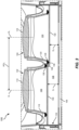
- a second IPD setting IPD 2 may correspond to the distance between the first and second optical axes A 1 , A 2 when the first and second optical lenses 114 are in a second position, as shown in FIG. 3 .
- the first eyecup 102 and the second eyecup 104 are closer to each other at the second IPD setting IPD 2 comparted to the first IPD setting IPD 1 .
- the first IPD setting IPD 1 may be useful for a user that has a generally wide IPD
- the second IPD setting IPD 2 may be useful for a different user that has a generally narrow IPD.
- the first transparent component 130 may be positioned a first distance D 1 from the single NED screen 106 and the second transparent component 132 may be positioned a second distance D 2 from the single NED screen 106.
- each of the first distance D 1 and the second distance D 2 may be in the range of about 10 mm to about 20 mm.
- the first distance D 1 may be different from the second distance D 2 .
- the first distance D 1 may be at least about 2 mm greater than the second distance D 2 .
- This difference between the first and second distances D 1 , D 2 may enable a portion of the first and second flanges 126, 128 between the first and second eyecups 102, 104 to overlap when the first and second eyecups 102, 104 are close together (e.g., at the second IPD setting IPD 2 ), as shown in FIG. 3 .
- the difference between the first and second distances D 1 , D 2 may facilitate the positioning of the first and second eyecups 102, 104 closer together than would otherwise be possible without the difference, since the first and second flanges 126, 128 are at different levels and thus do not physically interfere with each other at the second IPD setting IPD 2 .
- the single NED screen 106 may include an electronic display screen for presenting visual content to the user.
- the single NED screen 106 may include a liquid crystal display (LCD), light-emitting diode (LED) display, organic LED (OLED) display, a waveguide for directing light from a projector to the user, and/or any other suitable type of display screen.
- the single NED screen 106 may be configured for displaying respective stereoscopic images to the user through the first eyecup 102 and the second eyecup 104 to create an impression of a three-dimensional image.
- FIG. 4A illustrates a detailed cross-sectional view of a portion of an HMD assembly 400A.
- the HMD assembly 400A of FIG. 4A may include a first eyecup 402 and a second eyecup 404 respectively disposed over a first transparent component 420 and a second transparent component 432.
- the first eyecup 402 may include a first rigid housing 418 and the second eyecup 404 may include a second rigid housing 422.
- a first flange 426 may extend radially outward from a sidewall of the first rigid housing 418, and a second flange 428 may extend radially outward from a sidewall of the second rigid housing 422.
- a first sealing element 436 may be positioned between the first flange 426 and the first transparent component 430 to form a seal (e.g., a hermetic seal) between the first eyecup 402 and the first transparent component 430.
- a second sealing element 438 may be positioned between the second flange 428 and the second transparent component 432 to form a seal (e.g., a hermetic seal) between the second eyecup 404 and the second transparent component 432.
- the first flange 426 may include a first groove 442 in which a portion of the first sealing element 436 may be positioned.
- the first sealing element 436 may be coupled to the first flange 426 and may be movable along with the first flange 426 relative to the first transparent component 430.
- a first sliding interface 444 may be between the first sealing element 436 and the first transparent component 430.
- the second flange 428 may include a second groove 446 in which a portion of the second sealing element 438 may be positioned.
- the second sealing element 438 may be coupled to the second flange 428 and may be movable along with the second flange 428 relative to the second transparent component 432.
- a second sliding interface 448 may be between the second sealing element 438 and the second transparent component 432.
- the first and second eyecups 402, 404 and the first and second sealing elements 436, 438 may be movable relative to the first and second transparent components 430, 432.
- FIG. 4B illustrates a detailed cross-sectional view of a portion of an HMD assembly 400B having a different configuration than the HMD assembly 400A of FIG. 4A .
- the first groove 442 may be located in the first transparent component 430 and a portion of the first sealing element 436 may be positioned in the first groove 442.
- the first sliding interface 444 may be between the first sealing element 436 and the first flange 426.
- the second groove 446 may be located in the second transparent component 432 and a portion of the second sealing element 438 may be positioned in the second groove 446.
- the second sliding interface 448 may be between the second sealing element 438 and the second flange 428.
- the first and second eyecups 402, 404 may be movable relative to the first and second transparent components 430, 432 and relative to the first and second sealing elements 436, 438.
- FIG. 5 is a perspective view of a portion of an HMD assembly 500, according to additional embodiments of the present disclosure. Some components of the HMD assembly 500 are removed in FIG. 5 to better view underlying portions of the HMD assembly 500.
- the HMD assembly 500 of FIG. 5 may be similar to the HMD assembly 100 described above with reference to FIGS. 1A-3 .
- the HMD assembly 500 may include a first eyecup 502 and a second eyecup 504 positioned over a single NED screen 506.
- the eyecups 502, 504 and the single NED screen 506 may be coupled to and supported by an HMD support frame 510.
- the first eyecup 502 may include a first rigid housing 518 to which a first optical lens 514 may be coupled.
- the second eyecup 504 may include a second rigid housing 522 to which a second optical lens (not shown in the view of FIG. 5 for clarity) may be coupled.
- the first rigid housing 518 may at least partially define a first interior volume 520 of the first eyecup 502.
- the second rigid housing 522 may at least partially define a second interior volume 524 of the second eyecup 504.
- the first and second eyecups 502, 504 may be positioned over and movable relative to an enclosure 508 (shown in dashed lines in FIG. 5 ) that may be positioned over the single NED screen 506.
- the enclosure 508 may be hermetically sealed to inhibit the introduction of contamination on a user-facing surface of the single NED screen 506.
- the eyecups 502, 504 may be movable relative to each other and/or relative to the single NED screen 506, such as to adjust for the user's IPD.
- the HMD assembly 500 of FIG. 5 may also include an IPD adjustment mechanism 550, which may include a track 552 (e.g., a rod, a slide, etc.), a first IPD adjustment bracket 554 slidably coupling the first rigid housing 518 to the track 552, and a second IPD adjustment bracket 556 slidably coupling the second rigid housing 522 to the track 552.
- the IPD adjustment mechanism 550 may, in some examples, also include one or more IPD input mechanisms (not shown in the view of FIG.
- a cam, pusher, electromechanical actuator e.g., a motor, a linear actuator, etc.
- electromechanical actuator e.g., a motor, a linear actuator, etc.
- the IPD adjustment brackets 554, 556 may, in some embodiments, each include two spaced apart slider elements 558 engaged with and movable along the track 552, such as to provide sufficient stability to the respective eyecups 502, 504.
- the slider elements 558 may be engaged with the track 552 in a manner that maintains the eyecups 502, 504 in position after an IPD adjustment is made.
- a detent mechanism 560 (shown in FIG. 5 in dashed lines) may be employed to maintain the eyecups 502, 504 in their relative position after an IPD adjustment is made.
- the detent mechanism 560 may include a ratchet, a frictional interface, a pin and rack, or another suitable mechanism for maintaining the relative positions of the eyecups 502, 504.
- the HMD assembly 500 may optionally include another set of a track and IPD adjustment brackets positioned on an opposite side of the eyecups 502, 504 from the track 552 and IPD adjustment brackets 554, 556 shown in FIG. 5 , such as for additional mechanical stability.
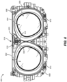
- FIG. 6 is a front view of an HMD assembly 600 that may include a first eyecup 602 (e.g., a left eyecup for positioning a first optical lens over a left eye of an intended user) and a second eyecup 604 (e.g., a right eyecup for positioning a second optical lens over a right eye of the intended user) positioned over a single NED screen 605.
- a first eyecup 602 e.g., a left eyecup for positioning a first optical lens over a left eye of an intended user
- a second eyecup 604 e.g., a right eyecup for positioning a second optical lens over a right eye of the intended user
- an enclosure may be positioned between the eyecups 602, 604 and the single NED screen 605.
- the eyecups 602, 604, and single NED screen may be mounted on an HMD support frame 608.
- the eyecups 602, 604 may be movable relative to the HMD support frame 608 and/or relative to each other to adjust for a user's IPD.
- each of the eyecups 602, 604 may be slidably coupled to and movable along an upper track 606 (e.g., a rod, a slide, etc.) that may be mounted on the HMD support frame 608.
- the eyecups 602, 604 may also be respectively slidably coupled to and movable along a first lower track 610 and a second lower track 612 that may be mounted on the HMD support frame 608.
- the first lower track 610 and second lower track 612 may be positioned on opposite sides of the eyecups 602, 604 from the upper track 606. As illustrated in FIG.
- first lower track 610 and second lower track 612 may be separated from each other, such as to accommodate an intended user's nose.
- first lower track 610 and second lower track 612 may be portions of a single, integral, unitary track.
- the HMD assembly 600 may also include a detent mechanism 614 to maintain the eyecups 602, 604 in position relative to each other and relative to the HMD support frame 608.
- the detent mechanism 614 may also be configured to keep each of the eyecups 602, 604 substantially equidistant from a lateral centerline of the HMD assembly 600.
- the detent mechanism 614 may include a first rack 616 extending inward from the first eyecup 602, a second rack 618 extending inward from the second eyecup 604, and a pinion 620 engaged with the first rack 616 and second rack 618.
- the pinion 620 may be rotatably coupled to the HMD support frame 608.
- Teeth of the pinion 620 may be engaged with teeth of the first rack 616 on a first side of the pinion 620 and with teeth of the second rack 618 on a second, opposite side of the pinion 620.
- the second eyecup 604 may also move inward (e.g., to the left from the perspective of FIG. 6 ) due to rotation of the pinion 620.
- the first eyecup 602 moves outward (e.g., to the left from the perspective of FIG. 6 )
- the second eyecup 604 may also move outward (e.g., to the right from the perspective of FIG. 6 ) due to rotation of the pinion 620 in an opposite direction.
- the detent mechanism 614 may include a feature that enables the eyecups 602, 604 to be maintained in position once moved.
- the eyecups 602, 604 may be maintained in two, three, four, or five distinct positions by the detent mechanism 614.
- An example embodiment of the detent mechanism 614 capable of maintaining the eyecups 602, 604 in position is illustrated in FIGS. 7 and 8 .
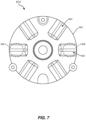
- FIG. 7 is a back view of the detent mechanism 614
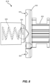
- FIG. 8 is a side view of the detent mechanism 614.
- the pinion 620 may be mounted on a detent base 622.
- the detent base 622 may include grooves 624 in a back face thereof that is opposite the pinion 620.
- One or more detent extensions 626 may be mounted to the HMD support frame 608 ( FIG. 6 ). In the embodiment shown, there are two detent extensions 626, although a single detent extensions 626 or more than two detent extensions 626 may be used in additional embodiments.
- the detent extensions 626 may be biased (e.g., spring-loaded) toward the detent base 622 and positioned relative to at least one of the grooves 624 to protrude into the respective grooves 624 when the detent extensions 626 and the grooves 624 are aligned with each other.
- the detent extensions 626 may include a ball that is biased toward the detent base 622 by a coil spring 628.
- the detent extensions 626 of the present disclosure are not limited to this configuration.
- the detent extensions 626 may have a cylindrical shape, a hemispherical shape, a pin shape, a shaft with a rounded end, a shaft with an angled end (e.g., having a triangular or trapezoidal longitudinal cross section), or any other suitable shape.
- the detent extension 626 may be biased toward the detent base 622 with a biasing element that is not a coil spring, such as a leaf spring, an elastomer, or another suitable biasing element.
- the detent mechanism 614 may be configured to position the eyecups 602 at predetermined IPD settings.
- the eyecups 602, 604 may be moved inward or outward by a user applying an inward or outward physical force directly on one or both of the eyecups 602, 604.
- an IPD adjustment mechanism may be used, such as the IPD adjustment mechanism 140 described above with reference to FIG. 1A or an electromechanical actuator.
- the first rack 616 and/or the second rack 618 may interact with the pinion 620 to rotate the pinion 620. Rotation of the pinion 620 may in turn rotate the detent base 622.
- the detent extensions 626 may be forced out of the respective grooves 624 against the biasing force applied by the coil spring 628. As the detent base 622 continues to rotate, the detent extensions 626 may be biased into other adjacent grooves 624, providing a tactile indication (e.g., a snap or click) to the user that the eyecups 602, 604 are at a predetermined IPD setting.
- the grooves 624 may be sized and spaced to correspond to a certain number of predetermined IPD settings, such as two (e.g., large and small), three (e.g., large, medium, and small), four, or five predetermined IPD settings.
- the grooves 624 may be sized and spaced to correspond to a first small IPD setting of about 58 mm measured between optical axes of the eyecups 602, 604, a second medium IPD setting of about 63 mm, and a third large IPD setting of about 68 mm.
- the HMD assembly 600 may also include an IPD indicator 630 to provide an indication of the current IPD setting.
- the IPD indicator 630 may include an aperture through a structure coupled to either the first eyecup 602 or the second eyecup 604. Beneath the aperture, there may be a visual indication of the IPD setting.
- the visual indication may include the letters S, M, and L corresponding to a small, medium, and large IPD setting.
- Other example visual indications may include numbers (e.g., 1 through 5 corresponding to five IPD settings, or 58, 63, and 68 corresponding to the IPD setting in millimeters, etc.), other letters (e.g., A through D corresponding to four IPD settings, "min,” “med,” and “max” corresponding to minimum, medium, and maximum IPD settings, etc.), colors (e.g., green, yellow, and red corresponding to three IPD settings, etc.), a diagram (e.g., showing eyes at different distances from each other, etc.), or combinations thereof.
- numbers e.g., 1 through 5 corresponding to five IPD settings, or 58, 63, and 68 corresponding to the IPD setting in millimeters, etc.
- other letters e.g., A through D corresponding to four IPD settings, "min,” “med,” and “max” corresponding to minimum, medium, and maximum IPD settings, etc.
- colors e.g., green, yellow, and red corresponding
- the aperture of the IPD indicator 630 may be aligned with one of the visual indications of the IPD settings, such that a user can view the visual indication through the aperture to determine the current IPD setting.
- FIG. 9 illustrates a portion of an HMD assembly 900 with an IPD position sensor 942.
- the HMD assembly 900 may be similar to the HMD assembly 600 of FIG. 6 .
- the HMD assembly 900 may include a first eyecup 902, a second eyecup 904, a single NED screen 905, a track 906 along which the eyecups 902, 904 may be movable for adjusting an IPD setting, an HMD support frame 908, a detent mechanism 914, and an IPD indicator 930.
- the IPD position sensor 942 may be configured to sense a lateral position of one or both of the eyecups 902, 904 relative to each other and/or relative to the HMD support frame 908.
- the IPD position sensor 942 may include a Hall effect sensor, a rotary encoder, a linear encoder, or another suitable position sensor.
- the IPD position sensor 942 is illustrated as a Hall effect sensor configured to sense a magnitude of a magnetic field of a moving magnet.
- the IPD position sensor 942 may include a probe 944 mounted to the HMD support frame 908 and a permanent magnet 946 mounted to one of the eyecups 902, 904.
- the permanent magnet 946 may move relative to the probe 944.
- the movement of the permanent magnet 946 may result in a change in magnitude of a magnetic field sensed by the probe 944.
- This change in magnitude sensed by the probe 944 may be correlated to a relative position between the probe 944 and the permanent magnet 946, and ultimately to a relative position between the eyecups 902, 904.
- the data from the IPD position sensor 942 may be used to determine the actual IPD setting of the eyecups 902, 904, such as for use by software to adjust an image displayed on the single NED screen 905, to provide an indication to the user of the IPD setting, etc.
- the probe 944 is mounted on the HMD support frame 908 and the permanent magnet 946 is mounted on one of the eyecups 902, 904.
- the probe 944 may be mounted on one of the eyecups 902, 904 and the permanent magnet 946 may be mounted on the HMD support frame 908, or the probe may be mounted on one of the eyecups 902, 904 and the permanent magnet 946 may be mounted on the other of the eyecups 902, 904.
- the permanent magnet 946 may be replaced by a non-permanent magnet, such as an electromagnet.
- the IPD position sensor 942 may be another type of position sensor other than a Hall effect sensor.
- FIG. 10 is a flow diagram illustrating a method 1000 of fabricating an HMD assembly, according to at least one embodiment of the present disclosure.
- a first transparent component and a second transparent component may be positioned and hermetically sealed over a single NED screen to form an enclosure.
- Operation 1010 may be performed in a variety of ways.
- the first transparent component may be positioned a first distance from the single NED screen and the second transparent component may be positioned a second, different distance from the single NED screen.
- the hermetic seal may be accomplished with sealing structure that may couple the transparent components to the single NED screen.
- a first eyecup supporting a first lens may be slidably positioned over the first transparent component.
- Operation 1020 may be performed in a variety of ways.
- a first sealing element may be positioned between the first eyecup and the first transparent component.
- a first sliding interface may be between the first eyecup and the first sealing element or, alternatively, may be between the first transparent component and the first sealing element.
- a second eyecup supporting a second lens may be slidably positioned over the second transparent component.
- Operation 1030 may be performed in a variety of ways.
- a second sealing element may be positioned between the second eyecup and the second transparent component.
- a second sliding interface may be between the second eyecup and the second sealing element or, alternatively, may be between the second transparent component and the second sealing element.
- the first eyecup and the second eyecup may be movable relative to each other, such as to adjust for an IPD of a user of the HMD assembly.
- the respective distances between the single NED screen and the first and second transparent components may be different, such as to allow flanges extending radially outward from the eyecups to at least partially overlap each other when an IPD setting of the eyecups is at its minimum operating position.
- the method 1000 may also include additional operations.
- an IPD adjustment mechanism may be assembled to the first eyecup and to the second eyecup in a position to move the first eyecup and the second eyecup relative to each other, such as to adjust for an IPD.
- FIG. 11 is a flow diagram illustrating a method 1100 of adjusting an interpupillary distance of an HMD assembly, according to at least one embodiment of the present disclosure.
- a first eyecup may be moved over a fist transparent component that is positioned over a single NED screen.
- a second may be moved over a second transparent component that is positioned over the single NED screen.
- Operations 1110 and 1120 may be performed in a variety of ways. For example, the eyecups may be moved toward or away from each other to adjust for a user's IPD.
- the single NED screen, the first transparent component, and the second transparent component may define a hermetically sealed enclosure.
- the present disclosure includes HMD assemblies and related methods that may enable IPD adjustments that inhibit (e.g., reduce or eliminate) the introduction of contamination onto a display screen.
- the disclosed HMD assemblies may include a single NED screen, which may reduce a cost of fabricating and operating the HMD assemblies.
- Various configurations and materials are disclosed, each of which may be advantageously employed for a variety of uses and applications.
- embodiments of the present disclosure may include or be implemented in conjunction with various types of artificial-reality systems.
- Artificial-reality content may include video, audio, haptic feedback, or some combination thereof, any of which may be presented in a single channel or in multiple channels (such as stereo video that produces a three-dimensional (3D) effect to the viewer).
- artificial reality may also be associated with applications, products, accessories, services, or some combination thereof, that are used to, e.g., create content in an artificial reality and/or are otherwise used in (e.g., to perform activities in) an artificial reality.
- Artificial-reality systems may be implemented in a variety of different form factors and configurations. Artificial-reality systems may include an NED that provides visibility into the real world (e.g., an augmented-reality system) or that visually immerses a user in an artificial reality (e.g., virtual-reality system 1200 in FIG. 12 ). While some artificial-reality devices may be self-contained systems, other artificial-reality devices may communicate and/or coordinate with external devices to provide an artificial-reality experience to a user. Examples of such external devices include handheld controllers, mobile devices, desktop computers, devices worn by a user, devices worn by one or more other users, and/or any other suitable external system.
- some artificial-reality systems may substantially replace one or more of a user's sensory perceptions of the real world with a virtual experience.
- a head-worn display system such as the virtual-reality system 1200 in FIG. 12 , that mostly or completely covers a user's field of view.
- the virtual-reality system 1200 may include a front rigid body 1202 and a band 1204 shaped to fit around a user's head.
- the virtual-reality system 1200 may also include output audio transducers 1206(A) and 1206(B).
- the front rigid body 1202 may include one or more electronic elements, including one or more electronic displays, one or more inertial measurement units (IMUs), one or more tracking emitters or detectors, and/or any other suitable device or system for creating an artificial reality experience.
- IMUs inertial measurement units
- Artificial-reality systems may include a variety of types of visual feedback mechanisms.
- display devices in the virtual-reality system 1200 may include one or more liquid crystal displays (LCDs), light-emitting diode (LED) displays, organic LED (OLED) displays, and/or any other suitable type of display screen.
- LCDs liquid crystal displays
- LED light-emitting diode
- OLED organic LED
- artificial-reality systems may include a single display screen for both eyes.
- Some artificial-reality systems may also include optical subsystems having one or more lenses (e.g., conventional concave or convex lenses, Fresnel lenses, adjustable liquid lenses, etc.) through which a user may view a display screen.
- lenses e.g., conventional concave or convex lenses, Fresnel lenses, adjustable liquid lenses, etc.
- some artificial-reality systems may include one or more projection systems.
- display devices in the virtual-reality system 1200 may include micro-LED projectors that project light (using, e.g., a waveguide) into display devices, such as clear combiner lenses that allow ambient light to pass through.
- the display devices may refract the projected light toward a user's pupil and may enable a user to simultaneously view both artificial-reality content and the real world.
- Artificial-reality systems may also be configured with any other suitable type or form of image projection system.
- Artificial-reality systems may also include various types of computer vision components and subsystems.
- the virtual-reality system 1200 may include one or more optical sensors, such as two-dimensional (2D) or 3D cameras, time-of-flight depth sensors, single-beam or sweeping laser rangefinders, 3D LiDAR sensors, and/or any other suitable type or form of optical sensor.
- An artificial-reality system may process data from one or more of these sensors to identify a location of a user, to map the real world, to provide a user with context about real-world surroundings, and/or to perform a variety of other functions.
- Artificial-reality systems may also include one or more input and/or output audio transducers.
- the output audio transducers 1206(A), and 1206(B) may include voice coil speakers, ribbon speakers, electrostatic speakers, piezoelectric speakers, bone conduction transducers, cartilage conduction transducers, and/or any other suitable type or form of audio transducer.
- input audio transducers may include condenser microphones, dynamic microphones, ribbon microphones, and/or any other type or form of input transducer.
- a single transducer may be used for both audio input and audio output.
- artificial-reality systems may include tactile (i.e., haptic) feedback systems, which may be incorporated into headwear, gloves, body suits, handheld controllers, environmental devices (e.g., chairs, floormats, etc.), and/or any other type of device or system.
- Haptic feedback systems may provide various types of cutaneous feedback, including vibration, force, traction, texture, and/or temperature.
- Haptic feedback systems may also provide various types of kinesthetic feedback, such as motion and compliance.
- Haptic feedback may be implemented using motors, piezoelectric actuators, fluidic systems, and/or a variety of other types of feedback mechanisms.
- Haptic feedback systems may be implemented independent of other artificial-reality devices, within other artificial-reality devices, and/or in conjunction with other artificial-reality devices.
- artificial-reality systems may create an entire virtual experience or enhance a user's real-world experience in a variety of contexts and environments. For instance, artificial-reality systems may assist or extend a user's perception, memory, or cognition within a particular environment. Some systems may enhance a user's interactions with other people in the real world or may enable more immersive interactions with other people in a virtual world.
- Artificial-reality systems may also be used for educational purposes (e.g., for teaching or training in schools, hospitals, government organizations, military organizations, business enterprises, etc.), entertainment purposes (e.g., for playing video games, listening to music, watching video content, etc.), and/or for accessibility purposes (e.g., as hearing aids, visuals aids, etc.).
- the embodiments disclosed herein may enable or enhance a user's artificial-reality experience in one or more of these contexts and environments and/or in other contexts and environments.
- the artificial-reality system 1200 may be used with a variety of other types of devices to provide a more compelling artificial-reality experience.
- These devices may include haptic interfaces with transducers that provide haptic feedback and/or that collect haptic information about a user's interaction with an environment.
- the artificial-reality systems disclosed herein may include various types of haptic interfaces that detect or convey various types of haptic information, including tactile feedback (e.g., feedback that a user detects via nerves in the skin, which may also be referred to as cutaneous feedback) and/or kinesthetic feedback (e.g., feedback that a user detects via receptors located in muscles, joints, and/or tendons).
- tactile feedback e.g., feedback that a user detects via nerves in the skin, which may also be referred to as cutaneous feedback
- kinesthetic feedback e.g., feedback that a user detects via receptors located in muscles, joints, and/or tendons.
- Haptic feedback may be provided by interfaces positioned within a user's environment (e.g., chairs, tables, floors, etc.) and/or interfaces on articles that may be worn or carried by a user (e.g., gloves, wristbands, etc.).
- a vibrotactile system may be in the form of a wearable glove and/or wristband.
- the haptic device may include a flexible, wearable textile material that is shaped and configured for positioning against a user's hand and wrist, respectively.
- This disclosure also includes vibrotactile systems that may be shaped and configured for positioning against other human body parts, such as a finger, an arm, a head, a torso, a foot, or a leg.
- vibrotactile systems may also be in the form of a glove, a headband, an armband, a sleeve, a head covering, a sock, a shirt, or pants, among other possibilities.
- the term "textile” may include any flexible, wearable material, including woven fabric, non-woven fabric, leather, cloth, a flexible polymer material, composite materials, etc.
- Haptic wearables may be implemented in a variety of types of artificial-reality systems and environments.
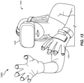
- FIG. 13 shows an example artificial-reality environment 1300 including one head-mounted virtual-reality display and two haptic devices (i.e., gloves), and in other embodiments any number and/or combination of these components and other components may be included in an artificial-reality system.
- Head-mounted display 1302 generally represents any type or form of virtual-reality system, such as the virtual-reality system 1200 in FIG. 12 .
- Haptic device 1304 generally represents any type or form of wearable device, worn by a use of an artificial-reality system, that provides haptic feedback to the user to give the user the perception that he or she is physically engaging with a virtual object.
- the haptic device 1304 may provide haptic feedback by applying vibration, motion, and/or force to the user.
- the haptic device 1304 may limit or augment a user's movement.
- the haptic device 1304 may limit a user's hand from moving forward so that the user has the perception that his or her hand has come in physical contact with a virtual wall.
- one or more actuators within the haptic advice may achieve the physical-movement restriction by pumping fluid into an inflatable bladder of the haptic device.
- a user may also use the haptic device 1304 to send action requests to a console. Examples of action requests include, without limitation, requests to start an application and/or end the application and/or requests to perform a particular action within the application.
- the haptic devices 1304 may include any suitable number and/or type of haptic transducer, sensor, and/or feedback mechanism.
- the haptic devices 1304 may include one or more mechanical transducers, piezoelectric transducers, and/or fluidic transducers.
- the haptic devices 1304 may also include various combinations of different types and forms of transducers that work together or independently to enhance a user's artificial-reality experience.
- a head-mounted display assembly which may include: a first eyecup and a second eyecup configured for respectively positioning a first lens and a second lens in front of intended locations of a user's eyes when the head-mounted display assembly is donned by the user; a single near-eye display screen configured for displaying an image to the user through the first eyecup and the second eyecup; and an enclosure over the single near-eye display screen, the enclosure including: a first transparent component positioned between the first lens and the single near-eye display screen; and a second transparent component positioned between the second lens and the single near-eye display screen, wherein the first eyecup and the second eyecup are movable relative to each other and relative to the first transparent component and the second transparent component to adjust for an interpupillary distance of the user's eyes.
- Example 2 The head-mounted display assembly of Example 1, wherein at least one of the first eyecup or the second eyecup is movable relative to the single near-eye display screen.
- Example 3 The head-mounted display assembly of Example 1 or Example 2, wherein the first transparent component is positioned a first distance from the single near-eye display screen and the second transparent component is positioned a second distance from the single near-eye display screen, wherein the second distance is less than the first distance.
- Example 4 The head-mounted display assembly of Example 3, wherein each of the first distance and the second distance is in a range of about 10 mm to about 20 mm.
- Example 5 The head-mounted display assembly of Example 3 or 4, wherein a difference between the first distance and the second distance is at least about 2 mm.
- Example 6 The head-mounted display assembly of any of Examples 1 through 5, wherein the first transparent component and the second transparent component may include at least one of: a polymer material; a glass material; or a crystalline material.
- Example 7 The head-mounted display assembly of any of Examples 1 through 6, wherein the enclosure may include a hermetically sealed enclosure defined over the single near-eye display screen and under the first transparent component and the second transparent component.
- Example 8 The head-mounted display assembly of any of Examples 1 through 7, wherein the first transparent component and the second transparent component are positioned a distance from the single near-eye display screen such that contaminants disposed on the first transparent component and the second transparent component are substantially out-of-focus to a user viewing the single near-eye display screen through the first lens and the second lens.
- Example 9 The head-mounted display assembly of any of Examples 1 through 8, which may further include a first sealing element positioned between the first eyecup and the first transparent component and a second sealing element positioned between the second eyecup and the second transparent component.
- Example 10 The head-mounted display assembly of Example 9, wherein a first sliding interface is between the first sealing element and the first transparent component and a second sliding interface is between the second sealing element and the second transparent component.
- Example 11 The head-mounted display assembly of Example 9, wherein a first sliding interface is between the first sealing element and the first eyecup and a second sliding interface is between the second sealing element and the second eyecup.
- Example 12 The head-mounted display assembly of any of Examples 9 through 11, wherein each of the first sealing element and the second sealing element may include at least one of: an elastomeric material; or a closed-cell foam material.
- Example 13 The head-mounted display assembly of any of Examples 1 through 12, wherein: the first eyecup may include a first sidewall and a first flange extending radially outward from the first sidewall adjacent to the first transparent component; and the second eyecup may include a second sidewall and a second flange extending radially outward from the second sidewall adjacent to the second transparent component.
- Example 14 The head-mounted display assembly of any of Examples 1 through 13, which may further include an interpupillary distance adjustment mechanism coupled to the first eyecup and to the second eyecup for adjusting a distance between the first eyecup and the second eyecup.
- Example 15 The head-mounted display assembly of Example 14, which may further include a detent mechanism configured to maintain a relative position of the first eyecup and the second eyecup after an adjustment is made for the interpupillary distance of the user's eyes.
- Example 16 The head-mounted display assembly of any of Examples 1 through 15, wherein the first eyecup and the second eyecup are movable relative to each other over a distance of up to about 10 mm.
- Example 17 A method of fabricating a head-mounted display assembly, which may include: hermetically sealing a first transparent component and a second transparent component over a single near-eye display screen to form an enclosure; slidably positioning a first eyecup supporting a first lens over the first transparent component; and slidably positioning a second eyecup supporting a second lens over the second transparent component, wherein the first eyecup and the second eyecup are positioned to move relative to each other and relative to the first transparent component and the second transparent component to adjust for an interpupillary distance of a user's eyes when the head-mounted display assembly is donned by the user.
- Example 18 The method of Example 17, which may further include: positioning a first sealing element between the first eyecup and the first transparent component; and positioning a second sealing element between the second eyecup and the second transparent component.
- Example 19 The method of Example 17 or 18, which may further include positioning the first transparent component at a first distance from the single near-eye display screen and positioning the second transparent component at a second distance from the single near-eye display screen, wherein the second distance is less than the first distance.
- Example 20 An artificial-reality device, which may include: a first eyecup including a first lens; a second eyecup including a second lens, wherein the first eyecup and the second eyecup are movable relative to each other to adjust for an interpupillary distance of a user's eyes; a single near-eye display screen configured for displaying an image to the user through the first eyecup and the second eyecup; at least one processor configured for rendering the image for display on the single near-eye display screen; and an enclosure over the single near-eye display screen, the enclosure including: a first transparent component positioned between the first lens and the single near-eye display screen; and a second transparent component positioned between the second lens and the single near-eye display screen, wherein the first transparent component and the second transparent component are stationary relative to the single near-eye display screen.
- Example 21 A method of adjusting an interpupillary distance of a head-mounted display assembly, which may include: moving a first eyecup over a first transparent component that is positioned over a single near-eye display screen; and moving a second eyecup over a second transparent component that is positioned over the single near-eye display screen, wherein the single near-eye display screen, the first transparent component, and the second transparent component define a hermetically sealed enclosure.
Landscapes
- Physics & Mathematics (AREA)
- General Physics & Mathematics (AREA)
- Optics & Photonics (AREA)
- Stereoscopic And Panoramic Photography (AREA)
- User Interface Of Digital Computer (AREA)
Abstract
Description
- The accompanying drawings illustrate a number of example embodiments and are a part of the specification. Together with the following description, these drawings demonstrate and explain various principles of the present disclosure.
-
FIG. 1A is a perspective view andFIG. 1B is a cross-sectional side view of a head-mounted display assembly, according to at least one embodiment of the present disclosure. -
FIG. 2 is a detailed cross-sectional side view of the head-mounted display assembly ofFIG. 1 with optical lenses at a first IPD setting, according to at least one additional embodiment of the present disclosure. -
FIG. 3 is a detailed cross-sectional side view of the head-mounted display assembly ofFIG. 1 with the optical lenses at a second IPD setting, according to at least one embodiment of the present disclosure. -
FIGS. 4A and 4B are detailed cross-sectional views of portions of head-mounted display assemblies, according to at least some embodiments of the present disclosure. -
FIG. 5 is a perspective view of a head-mounted display assembly, according to at least one embodiment of the present disclosure. -
FIG. 6 is a front view of a head-mounted display assembly, according to at least one additional embodiment of the present disclosure. -
FIG. 7 is a back view of a detent mechanism of the head-mounted display assembly ofFIG. 6 , according to at least one embodiment of the present disclosure. -
FIG. 8 is a side view of the detent mechanism ofFIG. 7 . -
FIG. 9 is a perspective view of a portion of a head-mounted display assembly including a position sensor, according to at least one embodiment of the present disclosure. -
FIG. 10 is a flow diagram illustrating a method of fabricating a head-mounted display assembly, according to at least one embodiment of the present disclosure. -
FIG. 11 is a flow diagram illustrating a method of adjusting an interpupillary distance of a head-mounted display assembly, according to at least one embodiment of the present disclosure. -
FIG. 12 is an illustration of an example virtual-reality headset that may be used in connection with embodiments of this disclosure. -
FIG. 13 is an illustration of an example virtual-reality environment according to embodiments of this disclosure. - Throughout the drawings, identical reference characters and descriptions indicate similar, but not necessarily identical, elements. While the example embodiments described herein are susceptible to various modifications and alternative forms, specific embodiments have been shown by way of example in the drawings and will be described in detail herein. However, the example embodiments described herein are not intended to be limited to the particular forms disclosed. Rather, the present disclosure covers all modifications, equivalents, and alternatives falling within the scope of the appended claims.
- Artificial-reality systems, such as virtual-reality systems or augmented-reality systems, typically display computer-generated content to users in order to create immersive experiences. The content may be displayed on a head-mounted display ("HMD") screen. For example, a virtual-reality system may create three-dimensional renderings to simulate an environment or a virtual space. Alternatively, augmented-reality systems may merge computer-generated content with a user's view of a real-world environment to enhance interactions with the real-world environment. These systems may provide users with the ability to navigate and alter digital content that may provide helpful information about real-world objects. HMD systems sometimes include two optical lenses-one for each eye-positioned in front of the screen. The lenses may magnify and/or provide an appropriate focus to images displayed on the screen. Contamination (e.g., dust particles, fingerprints, etc.) on the lenses or the screen can undesirably block or otherwise obscure portions of a displayed image. Moving parts in HMD systems can sometimes produce or move contamination in front of the displayed image.
- Different users have different head and face shapes and sizes. For example, a particular user's eyes may be located closer or farther apart from each other, compared to other users. The distance between the center of an HMD user's pupils is commonly referred to as "interpupillary distance" or "IPD." Positioning the lenses to match a particular user's IPD improves picture quality for that user. To accommodate different IPDs, some HMDs include a mechanism to adjust an IPD setting and, therefore, a relative position between the optical lenses. Some HMDs include two separate screens coupled to the two respective lenses. Each lens and screen pair may be movable relative to the other lens and screen pair to adjust for IPD. Each lens and screen pair may include a sealed interior to inhibit the introduction of contamination, to improve or maintain picture quality. However, two such screens are generally more expensive to integrate into HMDs compared to a single screen. However, conventional HMD systems with one screen and IPD adjustment capability generally have a configuration that may allow contamination to be introduced onto the screen and/or onto a screen side of the lenses.
- The present disclosure is generally directed to HMD assemblies that may include a single near-eye display ("NED") screen and two eyecups that are movable relative to each other to adjust for IPDs of different users. An enclosure may be disposed over the single NED screen. The enclosure may include a first transparent component positioned between the first lens and the single NED screen and a second transparent component positioned between the second lens and the single NED screen.
- The enclosure, including the first and second transparent components, may provide a clean volume over the single NED screen to reduce contamination on the screen while also allowing for interpupillary adjustments. As will be explained in greater detail below, embodiments of the present disclosure may enable IPD adjustments over a single, sealed display screen. The single display screen may reduce a cost of HMD assemblies with IPD adjustability, compared to conventional HMD assemblies with two separate display screens. Additionally, the enclosure over the single NED screen may facilitate keeping the screen clean and substantially free from contamination, which might otherwise obstruct a user's view of blocked pixels of the display screen. Contamination (e.g., dust, particles, other debris) that may be present between the first and second lenses and the respective first and second transparent components may be substantially out-of-focus. The out-of-focus contamination, if sufficiently small, may be essentially invisible to the user. Even larger contamination may be less visible than if the contamination were positioned at the NED screen surface.
- In some examples, the term "substantially" in reference to a given parameter, property, or condition may mean and include to a degree that one of ordinary skill in the art would understand that the given parameter, property, or condition is met with a small degree of variance, such as within acceptable manufacturing tolerances. By way of example, depending on the particular parameter, property, or condition that is substantially met, the parameter, property, or condition may be at least 90% met, at least 95% met, or even at least 99% met.
- Features from any of the embodiments described herein may be used in combination with one another in accordance with the general principles described herein. These and other embodiments, features, and advantages will be more fully understood upon reading the following detailed description in conjunction with the accompanying drawings and claims.
- The following will provide, with reference to
FIGS. 1A-3 , detailed descriptions of various example HMD assemblies according to the present disclosure. With reference toFIGS. 4A and 4B , the following will provide detailed descriptions of example sliding interfaces for IPD adjustability of HMD assemblies of the present disclosure. With reference toFIG. 5 , the following will provide detailed descriptions of example HMD assemblies according to additional embodiments of the present disclosure. With reference toFIGS. 10 and11 , the following will provide detailed descriptions of example methods of fabricating HMD assemblies and of adjusting an IPD of HMD assemblies, respectively. With reference toFIGS. 8 and9 , the following will provide detailed descriptions of example artificial-reality systems and environments that may be used in conjunction with HMD assemblies of the present disclosure. -
FIGS. 1A and 1B illustrate anHMD assembly 100 that may include afirst eyecup 102 and asecond eyecup 104 positioned over asingle NED screen 106, with anenclosure 108 positioned between theeyecups single NED screen 106.FIG. 2 illustrates a detailed view of certain components of theHMD assembly 100. Referring toFIGS. 1A-2 , theeyecups single NED screen 106, andenclosure 108 may be mounted on anHMD support frame 110, which may also support aneye bracket 112 that may be shaped and positioned for resting against the user's face when theHMD assembly 100 is donned by the user. In some examples, aflexible shroud 109 may be positioned over at least portions (e.g., peripheral portions) of theeyecups HMD assembly 100. - In some examples, relational terms, such as "first," "second," "upper," "lower," "over," "underlying," etc., may be used for clarity and convenience in understanding the disclosure and accompanying drawings and may not necessarily connote or depend on any specific preference, orientation, or order, except where the context clearly indicates otherwise.
- The
eyecups HMD assembly 100 is donned by the user. For example, thefirst eyecup 102 may be configured for viewing thesingle NED screen 106 with the user's left eye and thesecond eyecup 104 may be configured for viewing thesingle NED screen 106 with the user's right eye. Thefirst eyecup 102 may support a firstoptical lens 114 and thesecond eyecup 104 may support a secondoptical lens 116. For example, each of theoptical lenses optical lenses - The
first eyecup 102 may include a firstrigid housing 118 at least partially defining a firstinterior volume 120. Similarly, thesecond eyecup 104 may include a secondrigid housing 122 at least partially defining a secondinterior volume 124. A base of the firstrigid housing 118 may include afirst flange 126, which may extend radially outward from a sidewall of the firstrigid housing 118. Similarly, a base of the secondrigid housing 122 may include asecond flange 128, which may extend radially outward from a sidewall of the secondrigid housing 122. - The
optical lenses rigid housings optical lenses single NED screen 106 to the user's eyes when theHMD assembly 100 is donned by the user. - The
enclosure 108 may include a firsttransparent component 130 positioned between the firstoptical lens 114 and thesingle NED screen 106 and a secondtransparent component 132 positioned between the secondoptical lens 116 and thesingle NED screen 106. An outer region of the first and secondtransparent components single NED screen 106 via a sealingstructure 134 of theHMD support frame 110. Thus, theenclosure 108 may be defined by the first and secondtransparent components single NED screen 106, and the sealingstructure 134. In some examples, theenclosure 108 may be a hermetically sealed enclosure to inhibit the introduction of contaminants (e.g., particles) on the eye-facing surface of thesingle NED screen 106. Contamination that may be present over the first and second transparent components 130 (e.g., outside of the enclosure 108) may be substantially out-of-focus to a user viewing thesingle NED screen 106 through theoptical lenses - By way of example and not limitation, the first and second
transparent components transparent components transparent components transparent components single NED screen 106, theeye bracket 112, and the sealingstructure 134. By configuring the first and secondtransparent components single NED screen 106, the number of moving parts adjacent to thesingle NED screen 106 that might otherwise generate or move contaminants (e.g., particles) may be reduced. - A
first sealing element 136 may be disposed between thefirst flange 126 and the firsttransparent component 130. Asecond sealing element 138 may be disposed between thesecond flange 128 and the secondtransparent component 130. The first andsecond sealing elements first eyecup 102 and thesecond eyecup 104 to move (e.g., slide) relative to the first and secondtransparent components HMD assembly 100. The first andsecond sealing elements interior volumes - By way of example and not limitation, the first and second sealing elements 136,138 may each be an O-ring, a foam (e.g., closed-cell foam) ring, a foam ring bonded to a structural base (e.g., a foam ring bonded to a polyethylene terephthalate base), a V-ring, an X-ring, a gasket, etc. The material of the first and
second sealing elements - As noted above, the
first eyecup 102 and thesecond eyecup 104 may be movable (e.g., in a direction that is parallel to a surface of thesingle NED screen 106, such as in a left-and-right direction from the perspective ofFIGS. 1A and 1B ) relative to each other to adjust for an IPD of the user's eyes. At least one of theeyecups single NED screen 106. In some embodiments, thefirst eyecup 102 and thesecond eyecup 104 may be movable relative to each other over a distance of up to about 10 mm. Theeyecups HMD support frame 110, or theeyecups single NED screen 106. - As shown in
FIG. 1 by way of example, one or more IPD input mechanisms 140 (e.g., switches, sliders, knobs, buttons, etc.) may be integrated into theHMD support frame 110 and configured to allow the user of theHMD assembly 100 to adjust the IPD of theeyecups HMD assembly 100 or by the user's manipulation of the IPD input mechanism(s) 140. - A first IPD setting IPD1 may correspond to a distance between a first optical axis A1 of the first
optical lens 114 and a second optical axis A2 of the secondoptical lens 116 when the first and secondoptical lenses 114 are in a first position, as shown inFIG. 2 . A second IPD setting IPD2 may correspond to the distance between the first and second optical axes A1, A2 when the first and secondoptical lenses 114 are in a second position, as shown inFIG. 3 . In the example shown, thefirst eyecup 102 and thesecond eyecup 104 are closer to each other at the second IPD setting IPD2 comparted to the first IPD setting IPD1. Thus, the first IPD setting IPD1 may be useful for a user that has a generally wide IPD, and the second IPD setting IPD2 may be useful for a different user that has a generally narrow IPD. - Referring
FIGS. 2 and3 , the firsttransparent component 130 may be positioned a first distance D1 from thesingle NED screen 106 and the secondtransparent component 132 may be positioned a second distance D2 from thesingle NED screen 106. By way of example and not limitation, each of the first distance D1 and the second distance D2 may be in the range of about 10 mm to about 20 mm. - In some embodiments, the first distance D1 may be different from the second distance D2. For example, the first distance D1 may be at least about 2 mm greater than the second distance D2. This difference between the first and second distances D1, D2 may enable a portion of the first and
second flanges second eyecups second eyecups FIG. 3 . Thus, the difference between the first and second distances D1, D2 may facilitate the positioning of the first andsecond eyecups second flanges - The
single NED screen 106 may include an electronic display screen for presenting visual content to the user. For example, thesingle NED screen 106 may include a liquid crystal display (LCD), light-emitting diode (LED) display, organic LED (OLED) display, a waveguide for directing light from a projector to the user, and/or any other suitable type of display screen. In some embodiments, thesingle NED screen 106 may be configured for displaying respective stereoscopic images to the user through thefirst eyecup 102 and thesecond eyecup 104 to create an impression of a three-dimensional image. -
FIG. 4A illustrates a detailed cross-sectional view of a portion of anHMD assembly 400A. Like theHMD assembly 100 described above with reference toFIGS. 1A-3 , theHMD assembly 400A ofFIG. 4A may include afirst eyecup 402 and asecond eyecup 404 respectively disposed over a first transparent component 420 and a secondtransparent component 432. Thefirst eyecup 402 may include a firstrigid housing 418 and thesecond eyecup 404 may include a secondrigid housing 422. Afirst flange 426 may extend radially outward from a sidewall of the firstrigid housing 418, and asecond flange 428 may extend radially outward from a sidewall of the secondrigid housing 422. Afirst sealing element 436 may be positioned between thefirst flange 426 and the firsttransparent component 430 to form a seal (e.g., a hermetic seal) between thefirst eyecup 402 and the firsttransparent component 430. Likewise, asecond sealing element 438 may be positioned between thesecond flange 428 and the secondtransparent component 432 to form a seal (e.g., a hermetic seal) between thesecond eyecup 404 and the secondtransparent component 432. - By way of example and not limitation, the
first flange 426 may include afirst groove 442 in which a portion of thefirst sealing element 436 may be positioned. Thus, thefirst sealing element 436 may be coupled to thefirst flange 426 and may be movable along with thefirst flange 426 relative to the firsttransparent component 430. A first slidinginterface 444 may be between thefirst sealing element 436 and the firsttransparent component 430. Similarly, thesecond flange 428 may include asecond groove 446 in which a portion of thesecond sealing element 438 may be positioned. Thesecond sealing element 438 may be coupled to thesecond flange 428 and may be movable along with thesecond flange 428 relative to the secondtransparent component 432. A second slidinginterface 448 may be between thesecond sealing element 438 and the secondtransparent component 432. In this case, to adjust for a user's IPD, the first andsecond eyecups second sealing elements transparent components -
FIG. 4B illustrates a detailed cross-sectional view of a portion of anHMD assembly 400B having a different configuration than theHMD assembly 400A ofFIG. 4A . In this example, thefirst groove 442 may be located in the firsttransparent component 430 and a portion of thefirst sealing element 436 may be positioned in thefirst groove 442. Thus, the first slidinginterface 444 may be between thefirst sealing element 436 and thefirst flange 426. Similarly, thesecond groove 446 may be located in the secondtransparent component 432 and a portion of thesecond sealing element 438 may be positioned in thesecond groove 446. Thus, the second slidinginterface 448 may be between thesecond sealing element 438 and thesecond flange 428. In this case, to adjust for a user's IPD, the first andsecond eyecups transparent components second sealing elements -
FIG. 5 is a perspective view of a portion of anHMD assembly 500, according to additional embodiments of the present disclosure. Some components of theHMD assembly 500 are removed inFIG. 5 to better view underlying portions of theHMD assembly 500. TheHMD assembly 500 ofFIG. 5 may be similar to theHMD assembly 100 described above with reference toFIGS. 1A-3 . For example, theHMD assembly 500 may include afirst eyecup 502 and asecond eyecup 504 positioned over asingle NED screen 506. Theeyecups single NED screen 506 may be coupled to and supported by anHMD support frame 510. Thefirst eyecup 502 may include a firstrigid housing 518 to which a firstoptical lens 514 may be coupled. Thesecond eyecup 504 may include a secondrigid housing 522 to which a second optical lens (not shown in the view ofFIG. 5 for clarity) may be coupled. The firstrigid housing 518 may at least partially define a firstinterior volume 520 of thefirst eyecup 502. Similarly, the secondrigid housing 522 may at least partially define a secondinterior volume 524 of thesecond eyecup 504. - The first and
second eyecups FIG. 5 ) that may be positioned over thesingle NED screen 506. Theenclosure 508 may be hermetically sealed to inhibit the introduction of contamination on a user-facing surface of thesingle NED screen 506. - The
eyecups single NED screen 506, such as to adjust for the user's IPD. TheHMD assembly 500 ofFIG. 5 may also include anIPD adjustment mechanism 550, which may include a track 552 (e.g., a rod, a slide, etc.), a firstIPD adjustment bracket 554 slidably coupling the firstrigid housing 518 to thetrack 552, and a secondIPD adjustment bracket 556 slidably coupling the secondrigid housing 522 to thetrack 552. TheIPD adjustment mechanism 550 may, in some examples, also include one or more IPD input mechanisms (not shown in the view ofFIG. 5 , but similar to theIPD input mechanism 140 described above) with which the user may interact to control the movement of theeyecups IPD adjustment brackets eyecups track 552. - As illustrated in
FIG. 5 , theIPD adjustment brackets slider elements 558 engaged with and movable along thetrack 552, such as to provide sufficient stability to therespective eyecups slider elements 558 may be engaged with thetrack 552 in a manner that maintains theeyecups FIG. 5 in dashed lines) may be employed to maintain theeyecups detent mechanism 560 may include a ratchet, a frictional interface, a pin and rack, or another suitable mechanism for maintaining the relative positions of theeyecups HMD assembly 500 may optionally include another set of a track and IPD adjustment brackets positioned on an opposite side of theeyecups track 552 andIPD adjustment brackets FIG. 5 , such as for additional mechanical stability. -
FIG. 6 is a front view of anHMD assembly 600 that may include a first eyecup 602 (e.g., a left eyecup for positioning a first optical lens over a left eye of an intended user) and a second eyecup 604 (e.g., a right eyecup for positioning a second optical lens over a right eye of the intended user) positioned over asingle NED screen 605. As discussed above, an enclosure may be positioned between theeyecups single NED screen 605. Theeyecups HMD support frame 608. - The
eyecups HMD support frame 608 and/or relative to each other to adjust for a user's IPD. For example, each of theeyecups HMD support frame 608. Theeyecups lower track 610 and a secondlower track 612 that may be mounted on theHMD support frame 608. The firstlower track 610 and secondlower track 612 may be positioned on opposite sides of theeyecups upper track 606. As illustrated inFIG. 6 , in some examples the firstlower track 610 and secondlower track 612 may be separated from each other, such as to accommodate an intended user's nose. In additional examples, the firstlower track 610 and secondlower track 612 may be portions of a single, integral, unitary track. - The
HMD assembly 600 may also include adetent mechanism 614 to maintain theeyecups HMD support frame 608. In some embodiments, thedetent mechanism 614 may also be configured to keep each of theeyecups HMD assembly 600. As illustrated inFIG. 6 , thedetent mechanism 614 may include afirst rack 616 extending inward from thefirst eyecup 602, asecond rack 618 extending inward from thesecond eyecup 604, and apinion 620 engaged with thefirst rack 616 andsecond rack 618. Thepinion 620 may be rotatably coupled to theHMD support frame 608. Teeth of thepinion 620 may be engaged with teeth of thefirst rack 616 on a first side of thepinion 620 and with teeth of thesecond rack 618 on a second, opposite side of thepinion 620. Thus, when thefirst eyecup 602 moves inward (e.g., to the right from the perspective ofFIG. 6 ), thesecond eyecup 604 may also move inward (e.g., to the left from the perspective ofFIG. 6 ) due to rotation of thepinion 620. Similarly, when thefirst eyecup 602 moves outward (e.g., to the left from the perspective ofFIG. 6 ), thesecond eyecup 604 may also move outward (e.g., to the right from the perspective ofFIG. 6 ) due to rotation of thepinion 620 in an opposite direction. - The
detent mechanism 614 may include a feature that enables theeyecups eyecups detent mechanism 614. An example embodiment of thedetent mechanism 614 capable of maintaining theeyecups FIGS. 7 and8 . -
FIG. 7 is a back view of thedetent mechanism 614, andFIG. 8 is a side view of thedetent mechanism 614. As shown inFIG. 8 , thepinion 620 may be mounted on adetent base 622. As shown inFIGS. 7 and8 , thedetent base 622 may includegrooves 624 in a back face thereof that is opposite thepinion 620. One ormore detent extensions 626 may be mounted to the HMD support frame 608 (FIG. 6 ). In the embodiment shown, there are twodetent extensions 626, although asingle detent extensions 626 or more than twodetent extensions 626 may be used in additional embodiments. Thedetent extensions 626 may be biased (e.g., spring-loaded) toward thedetent base 622 and positioned relative to at least one of thegrooves 624 to protrude into therespective grooves 624 when thedetent extensions 626 and thegrooves 624 are aligned with each other. - For example, as shown in
FIGS. 7 and8 , thedetent extensions 626 may include a ball that is biased toward thedetent base 622 by acoil spring 628. However, thedetent extensions 626 of the present disclosure are not limited to this configuration. In additional embodiments, thedetent extensions 626 may have a cylindrical shape, a hemispherical shape, a pin shape, a shaft with a rounded end, a shaft with an angled end (e.g., having a triangular or trapezoidal longitudinal cross section), or any other suitable shape. In addition, thedetent extension 626 may be biased toward thedetent base 622 with a biasing element that is not a coil spring, such as a leaf spring, an elastomer, or another suitable biasing element. - The
detent mechanism 614 may be configured to position theeyecups 602 at predetermined IPD settings. For example, theeyecups eyecups IPD adjustment mechanism 140 described above with reference toFIG. 1A or an electromechanical actuator. When theeyecups 602, 604 (FIG. 6 ) are moved inward or outward, thefirst rack 616 and/or thesecond rack 618 may interact with thepinion 620 to rotate thepinion 620. Rotation of thepinion 620 may in turn rotate thedetent base 622. As thedetent base 622 rotates, thedetent extensions 626 may be forced out of therespective grooves 624 against the biasing force applied by thecoil spring 628. As thedetent base 622 continues to rotate, thedetent extensions 626 may be biased into otheradjacent grooves 624, providing a tactile indication (e.g., a snap or click) to the user that theeyecups grooves 624 may be sized and spaced to correspond to a certain number of predetermined IPD settings, such as two (e.g., large and small), three (e.g., large, medium, and small), four, or five predetermined IPD settings. In one example, thegrooves 624 may be sized and spaced to correspond to a first small IPD setting of about 58 mm measured between optical axes of theeyecups - Referring again to
FIG. 6 , in some examples, theHMD assembly 600 may also include anIPD indicator 630 to provide an indication of the current IPD setting. For example, theIPD indicator 630 may include an aperture through a structure coupled to either thefirst eyecup 602 or thesecond eyecup 604. Beneath the aperture, there may be a visual indication of the IPD setting. For example, the visual indication may include the letters S, M, and L corresponding to a small, medium, and large IPD setting. Other example visual indications may include numbers (e.g., 1 through 5 corresponding to five IPD settings, or 58, 63, and 68 corresponding to the IPD setting in millimeters, etc.), other letters (e.g., A through D corresponding to four IPD settings, "min," "med," and "max" corresponding to minimum, medium, and maximum IPD settings, etc.), colors (e.g., green, yellow, and red corresponding to three IPD settings, etc.), a diagram (e.g., showing eyes at different distances from each other, etc.), or combinations thereof. When thedetent mechanism 614 is used to set theeyecups IPD indicator 630 may be aligned with one of the visual indications of the IPD settings, such that a user can view the visual indication through the aperture to determine the current IPD setting. - Even with the
detent mechanism 614, theHMD assembly 600 may benefit from a position sensor to accurately measure and/or verify the current IPD setting of theHMD assembly 600.FIG. 9 illustrates a portion of anHMD assembly 900 with anIPD position sensor 942. In some respects, theHMD assembly 900 may be similar to theHMD assembly 600 ofFIG. 6 . For example, theHMD assembly 900 may include afirst eyecup 902, asecond eyecup 904, asingle NED screen 905, atrack 906 along which theeyecups HMD support frame 908, a detent mechanism 914, and anIPD indicator 930. - The
IPD position sensor 942 may be configured to sense a lateral position of one or both of theeyecups HMD support frame 908. For example, theIPD position sensor 942 may include a Hall effect sensor, a rotary encoder, a linear encoder, or another suitable position sensor. In the example shown inFIG. 9 , theIPD position sensor 942 is illustrated as a Hall effect sensor configured to sense a magnitude of a magnetic field of a moving magnet. TheIPD position sensor 942 may include aprobe 944 mounted to theHMD support frame 908 and apermanent magnet 946 mounted to one of theeyecups eyecups permanent magnet 946 may move relative to theprobe 944. The movement of thepermanent magnet 946 may result in a change in magnitude of a magnetic field sensed by theprobe 944. This change in magnitude sensed by theprobe 944 may be correlated to a relative position between theprobe 944 and thepermanent magnet 946, and ultimately to a relative position between theeyecups IPD position sensor 942 may be used to determine the actual IPD setting of theeyecups single NED screen 905, to provide an indication to the user of the IPD setting, etc. - In the embodiment illustrated in
FIG. 9 , theprobe 944 is mounted on theHMD support frame 908 and thepermanent magnet 946 is mounted on one of theeyecups probe 944 may be mounted on one of theeyecups permanent magnet 946 may be mounted on theHMD support frame 908, or the probe may be mounted on one of theeyecups permanent magnet 946 may be mounted on the other of theeyecups permanent magnet 946 may be replaced by a non-permanent magnet, such as an electromagnet. In additional embodiments, as noted above, theIPD position sensor 942 may be another type of position sensor other than a Hall effect sensor. -
FIG. 10 is a flow diagram illustrating amethod 1000 of fabricating an HMD assembly, according to at least one embodiment of the present disclosure. Atoperation 1010, a first transparent component and a second transparent component may be positioned and hermetically sealed over a single NED screen to form an enclosure.Operation 1010 may be performed in a variety of ways. For example, the first transparent component may be positioned a first distance from the single NED screen and the second transparent component may be positioned a second, different distance from the single NED screen. In some embodiments, the hermetic seal may be accomplished with sealing structure that may couple the transparent components to the single NED screen. - At
operation 1020, a first eyecup supporting a first lens may be slidably positioned over the first transparent component.Operation 1020 may be performed in a variety of ways. For example, a first sealing element may be positioned between the first eyecup and the first transparent component. A first sliding interface may be between the first eyecup and the first sealing element or, alternatively, may be between the first transparent component and the first sealing element. - At
operation 1030, a second eyecup supporting a second lens may be slidably positioned over the second transparent component.Operation 1030 may be performed in a variety of ways. For example, a second sealing element may be positioned between the second eyecup and the second transparent component. A second sliding interface may be between the second eyecup and the second sealing element or, alternatively, may be between the second transparent component and the second sealing element. The first eyecup and the second eyecup may be movable relative to each other, such as to adjust for an IPD of a user of the HMD assembly. In some embodiments, the respective distances between the single NED screen and the first and second transparent components may be different, such as to allow flanges extending radially outward from the eyecups to at least partially overlap each other when an IPD setting of the eyecups is at its minimum operating position. - In some examples, the
method 1000 may also include additional operations. For example, an IPD adjustment mechanism may be assembled to the first eyecup and to the second eyecup in a position to move the first eyecup and the second eyecup relative to each other, such as to adjust for an IPD. -
FIG. 11 is a flow diagram illustrating amethod 1100 of adjusting an interpupillary distance of an HMD assembly, according to at least one embodiment of the present disclosure. Atoperation 1110, a first eyecup may be moved over a fist transparent component that is positioned over a single NED screen. Atoperation 1120, a second may be moved over a second transparent component that is positioned over the single NED screen.Operations - Accordingly, the present disclosure includes HMD assemblies and related methods that may enable IPD adjustments that inhibit (e.g., reduce or eliminate) the introduction of contamination onto a display screen. At the same time, the disclosed HMD assemblies may include a single NED screen, which may reduce a cost of fabricating and operating the HMD assemblies. Various configurations and materials are disclosed, each of which may be advantageously employed for a variety of uses and applications.
- As noted above, embodiments of the present disclosure may include or be implemented in conjunction with various types of artificial-reality systems. Artificial-reality content may include video, audio, haptic feedback, or some combination thereof, any of which may be presented in a single channel or in multiple channels (such as stereo video that produces a three-dimensional (3D) effect to the viewer). Additionally, in some embodiments, artificial reality may also be associated with applications, products, accessories, services, or some combination thereof, that are used to, e.g., create content in an artificial reality and/or are otherwise used in (e.g., to perform activities in) an artificial reality.
- Artificial-reality systems may be implemented in a variety of different form factors and configurations. Artificial-reality systems may include an NED that provides visibility into the real world (e.g., an augmented-reality system) or that visually immerses a user in an artificial reality (e.g., virtual-
reality system 1200 inFIG. 12 ). While some artificial-reality devices may be self-contained systems, other artificial-reality devices may communicate and/or coordinate with external devices to provide an artificial-reality experience to a user. Examples of such external devices include handheld controllers, mobile devices, desktop computers, devices worn by a user, devices worn by one or more other users, and/or any other suitable external system. - As noted, some artificial-reality systems may substantially replace one or more of a user's sensory perceptions of the real world with a virtual experience. One example of this type of system is a head-worn display system, such as the virtual-
reality system 1200 inFIG. 12 , that mostly or completely covers a user's field of view. The virtual-reality system 1200 may include a frontrigid body 1202 and aband 1204 shaped to fit around a user's head. The virtual-reality system 1200 may also include output audio transducers 1206(A) and 1206(B). Furthermore, while not shown inFIG. 12 , the frontrigid body 1202 may include one or more electronic elements, including one or more electronic displays, one or more inertial measurement units (IMUs), one or more tracking emitters or detectors, and/or any other suitable device or system for creating an artificial reality experience. - Artificial-reality systems may include a variety of types of visual feedback mechanisms. For example, display devices in the virtual-
reality system 1200 may include one or more liquid crystal displays (LCDs), light-emitting diode (LED) displays, organic LED (OLED) displays, and/or any other suitable type of display screen. As discussed above artificial-reality systems may include a single display screen for both eyes. Some artificial-reality systems may also include optical subsystems having one or more lenses (e.g., conventional concave or convex lenses, Fresnel lenses, adjustable liquid lenses, etc.) through which a user may view a display screen. - In addition to or instead of using display screens, some artificial-reality systems may include one or more projection systems. For example, display devices in the virtual-
reality system 1200 may include micro-LED projectors that project light (using, e.g., a waveguide) into display devices, such as clear combiner lenses that allow ambient light to pass through. The display devices may refract the projected light toward a user's pupil and may enable a user to simultaneously view both artificial-reality content and the real world. Artificial-reality systems may also be configured with any other suitable type or form of image projection system. - Artificial-reality systems may also include various types of computer vision components and subsystems. For example, the virtual-
reality system 1200 may include one or more optical sensors, such as two-dimensional (2D) or 3D cameras, time-of-flight depth sensors, single-beam or sweeping laser rangefinders, 3D LiDAR sensors, and/or any other suitable type or form of optical sensor. An artificial-reality system may process data from one or more of these sensors to identify a location of a user, to map the real world, to provide a user with context about real-world surroundings, and/or to perform a variety of other functions. - Artificial-reality systems may also include one or more input and/or output audio transducers. In the example shown in
FIG. 12 , the output audio transducers 1206(A), and 1206(B) may include voice coil speakers, ribbon speakers, electrostatic speakers, piezoelectric speakers, bone conduction transducers, cartilage conduction transducers, and/or any other suitable type or form of audio transducer. Similarly, input audio transducers may include condenser microphones, dynamic microphones, ribbon microphones, and/or any other type or form of input transducer. In some embodiments, a single transducer may be used for both audio input and audio output. - While not shown in
FIG. 12 , artificial-reality systems may include tactile (i.e., haptic) feedback systems, which may be incorporated into headwear, gloves, body suits, handheld controllers, environmental devices (e.g., chairs, floormats, etc.), and/or any other type of device or system. Haptic feedback systems may provide various types of cutaneous feedback, including vibration, force, traction, texture, and/or temperature. Haptic feedback systems may also provide various types of kinesthetic feedback, such as motion and compliance. Haptic feedback may be implemented using motors, piezoelectric actuators, fluidic systems, and/or a variety of other types of feedback mechanisms. Haptic feedback systems may be implemented independent of other artificial-reality devices, within other artificial-reality devices, and/or in conjunction with other artificial-reality devices. - By providing haptic sensations, audible content, and/or visual content, artificial-reality systems may create an entire virtual experience or enhance a user's real-world experience in a variety of contexts and environments. For instance, artificial-reality systems may assist or extend a user's perception, memory, or cognition within a particular environment. Some systems may enhance a user's interactions with other people in the real world or may enable more immersive interactions with other people in a virtual world. Artificial-reality systems may also be used for educational purposes (e.g., for teaching or training in schools, hospitals, government organizations, military organizations, business enterprises, etc.), entertainment purposes (e.g., for playing video games, listening to music, watching video content, etc.), and/or for accessibility purposes (e.g., as hearing aids, visuals aids, etc.). The embodiments disclosed herein may enable or enhance a user's artificial-reality experience in one or more of these contexts and environments and/or in other contexts and environments.
- As noted, the artificial-
reality system 1200 may be used with a variety of other types of devices to provide a more compelling artificial-reality experience. These devices may include haptic interfaces with transducers that provide haptic feedback and/or that collect haptic information about a user's interaction with an environment. The artificial-reality systems disclosed herein may include various types of haptic interfaces that detect or convey various types of haptic information, including tactile feedback (e.g., feedback that a user detects via nerves in the skin, which may also be referred to as cutaneous feedback) and/or kinesthetic feedback (e.g., feedback that a user detects via receptors located in muscles, joints, and/or tendons). - Haptic feedback may be provided by interfaces positioned within a user's environment (e.g., chairs, tables, floors, etc.) and/or interfaces on articles that may be worn or carried by a user (e.g., gloves, wristbands, etc.). As an example, a vibrotactile system may be in the form of a wearable glove and/or wristband. The haptic device may include a flexible, wearable textile material that is shaped and configured for positioning against a user's hand and wrist, respectively. This disclosure also includes vibrotactile systems that may be shaped and configured for positioning against other human body parts, such as a finger, an arm, a head, a torso, a foot, or a leg. By way of example and not limitation, vibrotactile systems according to various embodiments of the present disclosure may also be in the form of a glove, a headband, an armband, a sleeve, a head covering, a sock, a shirt, or pants, among other possibilities. In some examples, the term "textile" may include any flexible, wearable material, including woven fabric, non-woven fabric, leather, cloth, a flexible polymer material, composite materials, etc.
- Haptic wearables may be implemented in a variety of types of artificial-reality systems and environments.
FIG. 13 shows an example artificial-reality environment 1300 including one head-mounted virtual-reality display and two haptic devices (i.e., gloves), and in other embodiments any number and/or combination of these components and other components may be included in an artificial-reality system. For example, in some embodiments there may be multiple head-mounted displays each having an associated haptic device, with each head-mounted display and each haptic device communicating with the same console, portable computing device, or other computing system. - Head-mounted
display 1302 generally represents any type or form of virtual-reality system, such as the virtual-reality system 1200 inFIG. 12 .Haptic device 1304 generally represents any type or form of wearable device, worn by a use of an artificial-reality system, that provides haptic feedback to the user to give the user the perception that he or she is physically engaging with a virtual object. In some embodiments, thehaptic device 1304 may provide haptic feedback by applying vibration, motion, and/or force to the user. For example, thehaptic device 1304 may limit or augment a user's movement. To give a specific example, thehaptic device 1304 may limit a user's hand from moving forward so that the user has the perception that his or her hand has come in physical contact with a virtual wall. In this specific example, one or more actuators within the haptic advice may achieve the physical-movement restriction by pumping fluid into an inflatable bladder of the haptic device. In some examples, a user may also use thehaptic device 1304 to send action requests to a console. Examples of action requests include, without limitation, requests to start an application and/or end the application and/or requests to perform a particular action within the application. - The
haptic devices 1304 may include any suitable number and/or type of haptic transducer, sensor, and/or feedback mechanism. For example, thehaptic devices 1304 may include one or more mechanical transducers, piezoelectric transducers, and/or fluidic transducers. Thehaptic devices 1304 may also include various combinations of different types and forms of transducers that work together or independently to enhance a user's artificial-reality experience. - By way of non-limiting examples, the following embodiments are included in the present disclosure.
- Example 1: A head-mounted display assembly, which may include: a first eyecup and a second eyecup configured for respectively positioning a first lens and a second lens in front of intended locations of a user's eyes when the head-mounted display assembly is donned by the user; a single near-eye display screen configured for displaying an image to the user through the first eyecup and the second eyecup; and an enclosure over the single near-eye display screen, the enclosure including: a first transparent component positioned between the first lens and the single near-eye display screen; and a second transparent component positioned between the second lens and the single near-eye display screen, wherein the first eyecup and the second eyecup are movable relative to each other and relative to the first transparent component and the second transparent component to adjust for an interpupillary distance of the user's eyes.
- Example 2: The head-mounted display assembly of Example 1, wherein at least one of the first eyecup or the second eyecup is movable relative to the single near-eye display screen.
- Example 3: The head-mounted display assembly of Example 1 or Example 2, wherein the first transparent component is positioned a first distance from the single near-eye display screen and the second transparent component is positioned a second distance from the single near-eye display screen, wherein the second distance is less than the first distance.
- Example 4: The head-mounted display assembly of Example 3, wherein each of the first distance and the second distance is in a range of about 10 mm to about 20 mm.
- Example 5: The head-mounted display assembly of Example 3 or 4, wherein a difference between the first distance and the second distance is at least about 2 mm.
- Example 6: The head-mounted display assembly of any of Examples 1 through 5, wherein the first transparent component and the second transparent component may include at least one of: a polymer material; a glass material; or a crystalline material.
- Example 7: The head-mounted display assembly of any of Examples 1 through 6, wherein the enclosure may include a hermetically sealed enclosure defined over the single near-eye display screen and under the first transparent component and the second transparent component.
- Example 8: The head-mounted display assembly of any of Examples 1 through 7, wherein the first transparent component and the second transparent component are positioned a distance from the single near-eye display screen such that contaminants disposed on the first transparent component and the second transparent component are substantially out-of-focus to a user viewing the single near-eye display screen through the first lens and the second lens.
- Example 9: The head-mounted display assembly of any of Examples 1 through 8, which may further include a first sealing element positioned between the first eyecup and the first transparent component and a second sealing element positioned between the second eyecup and the second transparent component.
- Example 10: The head-mounted display assembly of Example 9, wherein a first sliding interface is between the first sealing element and the first transparent component and a second sliding interface is between the second sealing element and the second transparent component.
- Example 11: The head-mounted display assembly of Example 9, wherein a first sliding interface is between the first sealing element and the first eyecup and a second sliding interface is between the second sealing element and the second eyecup.
- Example 12: The head-mounted display assembly of any of Examples 9 through 11, wherein each of the first sealing element and the second sealing element may include at least one of: an elastomeric material; or a closed-cell foam material.
- Example 13: The head-mounted display assembly of any of Examples 1 through 12, wherein: the first eyecup may include a first sidewall and a first flange extending radially outward from the first sidewall adjacent to the first transparent component; and the second eyecup may include a second sidewall and a second flange extending radially outward from the second sidewall adjacent to the second transparent component.
- Example 14: The head-mounted display assembly of any of Examples 1 through 13, which may further include an interpupillary distance adjustment mechanism coupled to the first eyecup and to the second eyecup for adjusting a distance between the first eyecup and the second eyecup.
- Example 15: The head-mounted display assembly of Example 14, which may further include a detent mechanism configured to maintain a relative position of the first eyecup and the second eyecup after an adjustment is made for the interpupillary distance of the user's eyes.
- Example 16: The head-mounted display assembly of any of Examples 1 through 15, wherein the first eyecup and the second eyecup are movable relative to each other over a distance of up to about 10 mm.
- Example 17: A method of fabricating a head-mounted display assembly, which may include: hermetically sealing a first transparent component and a second transparent component over a single near-eye display screen to form an enclosure; slidably positioning a first eyecup supporting a first lens over the first transparent component; and slidably positioning a second eyecup supporting a second lens over the second transparent component, wherein the first eyecup and the second eyecup are positioned to move relative to each other and relative to the first transparent component and the second transparent component to adjust for an interpupillary distance of a user's eyes when the head-mounted display assembly is donned by the user.
- Example 18: The method of Example 17, which may further include: positioning a first sealing element between the first eyecup and the first transparent component; and positioning a second sealing element between the second eyecup and the second transparent component.
- Example 19: The method of Example 17 or 18, which may further include positioning the first transparent component at a first distance from the single near-eye display screen and positioning the second transparent component at a second distance from the single near-eye display screen, wherein the second distance is less than the first distance.
- Example 20: An artificial-reality device, which may include: a first eyecup including a first lens; a second eyecup including a second lens, wherein the first eyecup and the second eyecup are movable relative to each other to adjust for an interpupillary distance of a user's eyes; a single near-eye display screen configured for displaying an image to the user through the first eyecup and the second eyecup; at least one processor configured for rendering the image for display on the single near-eye display screen; and an enclosure over the single near-eye display screen, the enclosure including: a first transparent component positioned between the first lens and the single near-eye display screen; and a second transparent component positioned between the second lens and the single near-eye display screen, wherein the first transparent component and the second transparent component are stationary relative to the single near-eye display screen.
- Example 21: A method of adjusting an interpupillary distance of a head-mounted display assembly, which may include: moving a first eyecup over a first transparent component that is positioned over a single near-eye display screen; and moving a second eyecup over a second transparent component that is positioned over the single near-eye display screen, wherein the single near-eye display screen, the first transparent component, and the second transparent component define a hermetically sealed enclosure.
- The process parameters and sequence of the steps described and/or illustrated herein are given by way of example only and can be varied as desired. For example, while the steps illustrated and/or described herein may be shown or discussed in a particular order, these steps do not necessarily need to be performed in the order illustrated or discussed. The various example methods described and/or illustrated herein may also omit one or more of the steps described or illustrated herein or include additional steps in addition to those disclosed.
-
- 1. A head-mounted display assembly, comprising: a first eyecup and a second eyecup configured for respectively positioning a first lens and a second lens in front of intended locations of a user's eyes when the head-mounted display assembly is donned by the user; a single near-eye display screen configured for displaying an image to the user through the first eyecup and the second eyecup; and an enclosure over the single near-eye display screen, the enclosure comprising: a first transparent component positioned between the first lens and the single near-eye display screen; and a second transparent component positioned between the second lens and the single near-eye display screen, wherein the first eyecup and the second eyecup are movable relative to each other and relative to the first transparent component and the second transparent component to adjust for an interpupillary distance of the user's eyes.
- 2. The head-mounted display assembly of
clause 1, wherein the first transparent component is positioned a first distance from the single near-eye display screen and the second transparent component is positioned a second distance from the single near-eye display screen, wherein the second distance is less than the first distance. - 3. The head-mounted display assembly of clause 2, wherein each of the first distance and the second distance is in a range of about 10 mm to about 20 mm and/or a difference between the first distance and the second distance is at least about 2 mm.
- 4. The head-mounted display assembly of
clause 1, wherein at least one of the first eyecup or the second eyecup is movable relative to the single near-eye display screen. - 5. The head-mounted display assembly of
clause 1, wherein the first transparent component and the second transparent component comprise at least one of: a polymer material; a glass material; or a crystalline material. - 6. The head-mounted display assembly of
clause 1, wherein the enclosure comprises a hermetically sealed enclosure defined over the single near-eye display screen and under the first transparent component and the second transparent component. - 7. The head-mounted display assembly of
clause 1, wherein the first transparent component and the second transparent component are positioned a distance from the single near-eye display screen such that contaminants disposed on the first transparent component and the second transparent component are substantially out-of-focus to a user viewing the single near-eye display screen through the first lens and the second lens. - 8. The head-mounted display assembly of
clause 1, further comprising a first sealing element positioned between the first eyecup and the first transparent component and a second sealing element positioned between the second eyecup and the second transparent component, and, optionally, wherein a first sliding interface is between the first sealing element and the first transparent component and a second sliding interface is between the second sealing element and the second transparent component, or a first sliding interface is between the first sealing element and the first eyecup and a second sliding interface is between the second sealing element and the second eyecup, and, further optionally, wherein each of the first sealing element and the second sealing element comprises at least one of: an elastomeric material; and a closed-cell foam material. - 9. The head-mounted display assembly of
clause 1, wherein: the first eyecup comprises a first sidewall and a first flange extending radially outward from the first sidewall adjacent to the first transparent component; and the second eyecup comprises a second sidewall and a second flange extending radially outward from the second sidewall adjacent to the second transparent component. - 10. The head-mounted display assembly of
clause 1, further comprising an interpupillary distance adjustment mechanism coupled to the first eyecup and to the second eyecup for adjusting a distance between the first eyecup and the second eyecup, and, optionally, further comprising a detent mechanism configured to maintain a relative position of the first eyecup and the second eyecup after an adjustment is made for the interpupillary distance of the user's eyes. - 11. The head-mounted display assembly of
clause 1, wherein the first eyecup and the second eyecup are movable relative to each other over a distance of up to about 10 mm. - 12. A method of fabricating a head-mounted display assembly, comprising: hermetically sealing a first transparent component and a second transparent component over a single near-eye display screen to form an enclosure; slidably positioning a first eyecup supporting a first lens over the first transparent component; and slidably positioning a second eyecup supporting a second lens over the second transparent component, wherein the first eyecup and the second eyecup are positioned to move relative to each other and relative to the first transparent component and the second transparent component to adjust for an interpupillary distance of a user's eyes when the head-mounted display assembly is donned by the user.
- 13. The method of clause 12, further comprising: positioning a first sealing element between the first eyecup and the first transparent component; and positioning a second sealing element between the second eyecup and the second transparent component.
- 14. The method of clause 12, further comprising positioning the first transparent component at a first distance from the single near-eye display screen and positioning the second transparent component at a second distance from the single near-eye display screen, wherein the second distance is less than the first distance.
- 15. An artificial-reality device, comprising: a first eyecup comprising a first lens; a second eyecup comprising a second lens, wherein the first eyecup and the second eyecup are movable relative to each other to adjust for an interpupillary distance of a user's eyes; a single near-eye display screen configured for displaying an image to the user through the first eyecup and the second eyecup; at least one processor configured for rendering the image for display on the single near-eye display screen; and an enclosure over the single near-eye display screen, the enclosure comprising: a first transparent component positioned between the first lens and the single near-eye display screen; and a second transparent component positioned between the second lens and the single near-eye display screen, wherein the first transparent component and the second transparent component are stationary relative to the single near-eye display screen.
- The preceding description has been provided to enable others skilled in the art to best utilize various aspects of the example embodiments disclosed herein. This example description is not intended to be exhaustive or to be limited to any precise form disclosed. Many modifications and variations are possible without departing from the spirit and scope of the present disclosure. The embodiments disclosed herein should be considered in all respects illustrative and not restrictive. Reference should be made to the appended claims and their equivalents in determining the scope of the present disclosure.
- Unless otherwise noted, the terms "connected to" and "coupled to" (and their derivatives), as used in the specification and claims, are to be construed as permitting both direct and indirect (i.e., via other elements or components) connection. In addition, the terms "a" or "an," as used in the specification and claims, are to be construed as meaning "at least one of." Finally, for ease of use, the terms "including" and "having" (and their derivatives), as used in the specification and claims, are interchangeable with and have the same meaning as the word "comprising."
Claims (23)
- A head-mounted display assembly, comprising:a first eyecup and a second eyecup configured for respectively positioning a first lens and a second lens in front of intended locations of a user's eyes when the head-mounted display assembly is donned by the user, wherein the first eyecup and the second eyecup are movable relative to each other to adjust for the user's interpupillary distance (IPD);a detent mechanism configured to hold the first eyecup and the second eyecup in at least two distinct distances from each other corresponding to at least two IPD settings of the first eyecup and second eyecup; andan IPD indicator configured to indicate a current IPD setting of the at least two IPD settings of the first eyecup and second eyecup.
- The head-mounted display assembly of claim 1, wherein the detent mechanism comprises at least one of:a ratchet;a frictional interface; ora pin and rack.
- The head-mounted display assembly of claim 1, further comprising a track along which the first eyecup and second eyecup are movable to adjust for the user's IPD, wherein:the first eyecup comprises a first IPD adjustment bracket engaged with the track; andthe second eyecup comprises a second IPD adjustment bracket engaged with the track.
- The head-mounted display assembly of claim 3, wherein the first IPD adjustment bracket includes at least one first slider element engaged with the track and the second IPD adjustment bracket includes at least one second slider element engaged with the track.
- The head-mounted display assembly of claim 4, wherein the at least one first slider element comprises two first slider elements and the at least one second slider element comprises two second slider elements.
- The head-mounted display assembly of claim 3, wherein the track comprises at least one of a rod or a slide.
- The head-mounted display assembly of claim 1, further comprising an IPD input mechanism for controlling movement of the first eyecup and second eyecup relative to each other.
- The head-mounted display assembly of claim 7, wherein the IPD input mechanism comprises an actuator configured to move the first eyecup and second eyecup relative to each other.
- The head-mounted display assembly of claim 1, wherein the detent mechanism comprises:a first rack extending inward from the first eyecup;a second rack extending inward from the second eyecup; anda pinion engaged with the first rack and the second rack.
- The head-mounted display assembly of claim 9, wherein the pinion is positioned between the first rack and the second rack.
- The head-mounted display assembly of claim 9, wherein the IPD indicator comprises an aperture and a visual indication of the IPD setting that is aligned with and visible through the aperture.
- The head-mounted display assembly of claim 9, wherein the detent mechanism further comprises:a detent base coupled to the pinion, the detent base including a plurality of grooves in a face thereof; andat least one detent extension biased toward the detent base to be positioned within a groove of the plurality of grooves to hold the pinion at an IPD setting of the at least two IPD settings.
- The head-mounted display assembly of claim 12, wherein the at least one detent extension comprises two detent extensions.
- The head-mounted display assembly of claim 12, wherein the at least one detent extension comprises a ball that is spring-biased toward the detent base.
- The head-mounted display assembly of claim 1, further comprising an IPD position sensor configured to sense the current IPD setting of the first eyecup and second eyecup.
- The head-mounted display assembly of claim 15, wherein the IPD position senor comprises a probe configured to sense a magnetic field and a permanent magnet coupled to at least one of the first eyecup or the second eyecup.
- The head-mounted display assembly of claim 1, wherein the first eyecup and the second eyecup are movable relative to each other over a distance of up to about 10 mm.
- An artificial-reality device, comprising:a first eyecup comprising a first lens;a second eyecup comprising a second lens, wherein the first eyecup and the second eyecup are movable relative to each other to adjust for an interpupillary distance (IPD) of a user's eyes;a near-eye display screen configured for displaying an image to the user through the first eyecup and the second eyecup;at least one processor configured for rendering the image for display on the near-eye display screen;a detent mechanism configured to hold the first eyecup and the second eyecup in at least two distinct distances from each other corresponding to at least two IPD settings of the first eyecup and second eyecup; andan IPD indicator configured to indicate a current IPD setting of at least two IPD settings of the first eyecup and second eyecup.
- The artificial-reality device of claim 18, wherein the detent mechanism comprises:a first rack extending inward from the first eyecup;a second rack extending inward from the second eyecup; anda pinion engaged with the first rack and the second rack.
- A method of fabricating a head-mounted display assembly, comprising:slidably positioning a first eyecup supporting a first lens to a frame;slidably positioning a second eyecup supporting a second lens to the frame, such that the first eyecup and the second eyecup are positioned to move relative to each other and relative to the frame to adjust for an interpupillary distance (IPD) of a user's eyes when the head-mounted display assembly is donned by the user;retaining the first eyecup and second eyecup in an IPD setting of multiple IPD settings with a detent mechanism; andaligning an IPD setting visual indication with an aperture such that the IPD setting visual indication can be viewed through the aperture.
- The method of claim 20, wherein aligning the IPD setting visual indication with the aperture comprises aligning a numerical visual indication with the aperture such that the numerical visual indication can be viewed through the aperture.
- The head-mounted display assembly of claim 11, wherein the visual indication of the IPD setting comprises at least one of numbers or letters.
- The artificial-reality device of claim 18, wherein the IPD indicator comprises an aperture and numbers corresponding to the at least two IPD settings, wherein the aperture is aligned with one of the numbers at each of the at least two IPD settings.
Applications Claiming Priority (5)
| Application Number | Priority Date | Filing Date | Title |
|---|---|---|---|
| US201962929932P | 2019-11-03 | 2019-11-03 | |
| US202063007586P | 2020-04-09 | 2020-04-09 | |
| US17/075,028 US11402642B2 (en) | 2019-11-03 | 2020-10-20 | Head-mounted display assemblies and related methods for interpupillary distance adjustments |
| EP20808251.1A EP4052085A1 (en) | 2019-11-03 | 2020-10-28 | Head-mounted display assemblies and related methods for interpupillary distance adjustments |
| PCT/US2020/057800 WO2021087009A1 (en) | 2019-11-03 | 2020-10-28 | Head-mounted display assemblies and related methods for interpupillary distance adjustments |
Related Parent Applications (1)
| Application Number | Title | Priority Date | Filing Date |
|---|---|---|---|
| EP20808251.1A Division EP4052085A1 (en) | 2019-11-03 | 2020-10-28 | Head-mounted display assemblies and related methods for interpupillary distance adjustments |
Publications (2)
| Publication Number | Publication Date |
|---|---|
| EP4215978A2 true EP4215978A2 (en) | 2023-07-26 |
| EP4215978A3 EP4215978A3 (en) | 2023-11-01 |
Family
ID=75687465
Family Applications (3)
| Application Number | Title | Priority Date | Filing Date |
|---|---|---|---|
| EP20808251.1A Pending EP4052085A1 (en) | 2019-11-03 | 2020-10-28 | Head-mounted display assemblies and related methods for interpupillary distance adjustments |
| EP22209723.0A Pending EP4215978A3 (en) | 2019-11-03 | 2020-10-28 | Head-mounted display assemblies and related methods for interpupillary distance adjustments |
| EP23169412.6A Pending EP4235262A3 (en) | 2019-11-03 | 2020-10-28 | Head-mounted display assemblies and related methods for interpupillary distance adjustments |
Family Applications Before (1)
| Application Number | Title | Priority Date | Filing Date |
|---|---|---|---|
| EP20808251.1A Pending EP4052085A1 (en) | 2019-11-03 | 2020-10-28 | Head-mounted display assemblies and related methods for interpupillary distance adjustments |
Family Applications After (1)
| Application Number | Title | Priority Date | Filing Date |
|---|---|---|---|
| EP23169412.6A Pending EP4235262A3 (en) | 2019-11-03 | 2020-10-28 | Head-mounted display assemblies and related methods for interpupillary distance adjustments |
Country Status (6)
| Country | Link |
|---|---|
| US (3) | US11402642B2 (en) |
| EP (3) | EP4052085A1 (en) |
| JP (1) | JP2023500561A (en) |
| KR (1) | KR20220093332A (en) |
| CN (2) | CN115728953A (en) |
| WO (1) | WO2021087009A1 (en) |
Families Citing this family (7)
| Publication number | Priority date | Publication date | Assignee | Title |
|---|---|---|---|---|
| US11054659B2 (en) * | 2019-11-07 | 2021-07-06 | Htc Corporation | Head mounted display apparatus and distance measurement device thereof |
| CN114167607A (en) * | 2020-09-11 | 2022-03-11 | 华为技术有限公司 | Optical imaging system and head-mounted display device |
| CN113489966B (en) * | 2021-05-17 | 2022-07-26 | 青岛小鸟看看科技有限公司 | System and method for detecting pupil distance adjusting position of VR device |
| TWM619524U (en) * | 2021-06-29 | 2021-11-11 | 廣達電腦股份有限公司 | Head-mounted display |
| WO2023048960A1 (en) * | 2021-09-23 | 2023-03-30 | Callisto Design Solutions Llc | Optical assembly tracking |
| CN116560082A (en) * | 2022-01-30 | 2023-08-08 | 北京字跳网络技术有限公司 | Pupil distance adjusting device, pupil distance adjusting method, pupil distance adjusting equipment and computer medium |
| US11846752B1 (en) | 2022-11-11 | 2023-12-19 | Htc Corporation | Head-mounted display device with adjustable interpupillary distance |
Family Cites Families (13)
| Publication number | Priority date | Publication date | Assignee | Title |
|---|---|---|---|---|
| ATE552478T1 (en) * | 2004-06-03 | 2012-04-15 | Making Virtual Solid L L C | NAVIGATIONAL DISPLAY METHOD AND APPARATUS FOR ON-GOING USING A HEAD-UP DISPLAY |
| US20090303315A1 (en) | 2006-02-23 | 2009-12-10 | Stereonics Limited | Binocular device using beam splitter (bino-view) |
| US20140375542A1 (en) * | 2013-06-25 | 2014-12-25 | Steve Robbins | Adjusting a near-eye display device |
| JP2017511041A (en) | 2014-02-18 | 2017-04-13 | マージ ラブス インコーポレイテッド | Head mounted display goggles for use with mobile computing devices |
| JP6218649B2 (en) * | 2014-03-11 | 2017-10-25 | オリンパス株式会社 | Virtual image observation optical system and light guide prism |
| US20160195723A1 (en) * | 2015-01-05 | 2016-07-07 | Seebright Inc. | Methods and apparatus for reflected display of images |
| US9472025B2 (en) * | 2015-01-21 | 2016-10-18 | Oculus Vr, Llc | Compressible eyecup assemblies in a virtual reality headset |
| KR102568772B1 (en) * | 2015-09-25 | 2023-08-22 | 삼성전자주식회사 | Connection Device for Display device and Head-mounted Display Device |
| US10725305B2 (en) * | 2015-10-07 | 2020-07-28 | Facebook Technologies, Llc | Lens movement assemblies for use with head mounted displays |
| US10175423B2 (en) * | 2017-05-31 | 2019-01-08 | Microsoft Technology Licensing, Llc | Optical waveguide using overlapping optical elements |
| US10798370B2 (en) * | 2017-08-30 | 2020-10-06 | Facebook Technologies, Llc | Apparatus, system, and method for interpupillary-distance-adjustable head-mounted displays |
| CN107783299A (en) * | 2017-12-02 | 2018-03-09 | 四川省汇泉罐头食品有限公司 | A kind of VR glasses of adjustable interpupillary distance |
| CN108803042B (en) * | 2018-07-06 | 2022-02-25 | 歌尔股份有限公司 | Head-mounted device |
-
2020
- 2020-10-20 US US17/075,028 patent/US11402642B2/en active Active
- 2020-10-28 CN CN202211560651.7A patent/CN115728953A/en active Pending
- 2020-10-28 EP EP20808251.1A patent/EP4052085A1/en active Pending
- 2020-10-28 JP JP2022517807A patent/JP2023500561A/en active Pending
- 2020-10-28 EP EP22209723.0A patent/EP4215978A3/en active Pending
- 2020-10-28 KR KR1020227017855A patent/KR20220093332A/en unknown
- 2020-10-28 WO PCT/US2020/057800 patent/WO2021087009A1/en unknown
- 2020-10-28 CN CN202080074498.XA patent/CN114600033A/en active Pending
- 2020-10-28 EP EP23169412.6A patent/EP4235262A3/en active Pending
-
2022
- 2022-07-29 US US17/876,924 patent/US11662594B2/en active Active
-
2023
- 2023-04-17 US US18/301,630 patent/US20230251498A1/en active Pending
Also Published As
| Publication number | Publication date |
|---|---|
| EP4052085A1 (en) | 2022-09-07 |
| CN115728953A (en) | 2023-03-03 |
| US20230251498A1 (en) | 2023-08-10 |
| EP4215978A3 (en) | 2023-11-01 |
| JP2023500561A (en) | 2023-01-10 |
| CN114600033A (en) | 2022-06-07 |
| WO2021087009A1 (en) | 2021-05-06 |
| US20220365356A1 (en) | 2022-11-17 |
| US11662594B2 (en) | 2023-05-30 |
| EP4235262A3 (en) | 2023-09-13 |
| US20210132397A1 (en) | 2021-05-06 |
| US11402642B2 (en) | 2022-08-02 |
| KR20220093332A (en) | 2022-07-05 |
| EP4235262A2 (en) | 2023-08-30 |
Similar Documents
| Publication | Publication Date | Title |
|---|---|---|
| US11662594B2 (en) | Head-mounted display assemblies and related methods for interpupillary distance adjustments | |
| EP1276333A2 (en) | Adaptive autostereoscopic display system | |
| US10901225B1 (en) | Systems and methods for positioning a head-mounted display | |
| US11720175B1 (en) | Spatially offset haptic feedback | |
| US20160358380A1 (en) | Head-Mounted Device and Method of Enabling Non-Stationary User to Perform 3D Drawing Interaction in Mixed-Reality Space | |
| US11397467B1 (en) | Tactile simulation of initial contact with virtual objects | |
| US11086392B1 (en) | Devices, systems, and methods for virtual representation of user interface devices | |
| US11231791B1 (en) | Handheld controllers for artificial reality and related methods | |
| US11125255B1 (en) | Complementary fluidic valves, logic gates, and latches | |
| US10819898B1 (en) | Imaging device with field-of-view shift control | |
| US11662812B2 (en) | Systems and methods for using a display as an illumination source for eye tracking | |
| US11480262B1 (en) | Complementary fluidic valves and systems | |
| US10962124B1 (en) | Fluidic latches, systems, and methods | |
| US11435593B1 (en) | Systems and methods for selectively augmenting artificial-reality experiences with views of real-world environments | |
| US11467411B1 (en) | Head-mounted display assemblies and related methods for interpupillary distance adjustments | |
| CN113685577A (en) | Microfluidic device and fluidic logic device | |
| US11143218B1 (en) | Complementary fluidic valves and logic gates | |
| US20230046155A1 (en) | Dynamic widget placement within an artificial reality display | |
| US11168768B1 (en) | Collaborative shear display | |
| US11467669B2 (en) | Operational feedback using capacitive sensing | |
| US11298623B1 (en) | Battery retention methods and mechanisms for handheld controllers | |
| US20200159027A1 (en) | Head-mounted display with unobstructed peripheral viewing | |
| US11474609B1 (en) | Systems and methods for haptic equalization | |
| US11519517B1 (en) | Fluidic devices with piezoelectric actuators and related methods | |
| US11662550B1 (en) | Systems and methods for varifocal adjustments |
Legal Events
| Date | Code | Title | Description |
|---|---|---|---|
| PUAI | Public reference made under article 153(3) epc to a published international application that has entered the european phase |
Free format text: ORIGINAL CODE: 0009012 |
|
| STAA | Information on the status of an ep patent application or granted ep patent |
Free format text: STATUS: THE APPLICATION HAS BEEN PUBLISHED |
|
| AC | Divisional application: reference to earlier application |
Ref document number: 4052085 Country of ref document: EP Kind code of ref document: P |
|
| AK | Designated contracting states |
Kind code of ref document: A2 Designated state(s): AL AT BE BG CH CY CZ DE DK EE ES FI FR GB GR HR HU IE IS IT LI LT LU LV MC MK MT NL NO PL PT RO RS SE SI SK SM TR |
|
| PUAL | Search report despatched |
Free format text: ORIGINAL CODE: 0009013 |
|
| AK | Designated contracting states |
Kind code of ref document: A3 Designated state(s): AL AT BE BG CH CY CZ DE DK EE ES FI FR GB GR HR HU IE IS IT LI LT LU LV MC MK MT NL NO PL PT RO RS SE SI SK SM TR |
|
| RIC1 | Information provided on ipc code assigned before grant |
Ipc: G02B 27/01 20060101AFI20230925BHEP |
|
| RAP3 | Party data changed (applicant data changed or rights of an application transferred) |
Owner name: META PLATFORMS TECHNOLOGIES, LLC |
|
| STAA | Information on the status of an ep patent application or granted ep patent |
Free format text: STATUS: REQUEST FOR EXAMINATION WAS MADE |
|
| 17P | Request for examination filed |
Effective date: 20240229 |
|
| RBV | Designated contracting states (corrected) |
Designated state(s): AL AT BE BG CH CY CZ DE DK EE ES FI FR GB GR HR HU IE IS IT LI LT LU LV MC MK MT NL NO PL PT RO RS SE SI SK SM TR |