EP4215859A1 - Wärmerohr-wärmetauscher - Google Patents
Wärmerohr-wärmetauscher Download PDFInfo
- Publication number
- EP4215859A1 EP4215859A1 EP22877346.1A EP22877346A EP4215859A1 EP 4215859 A1 EP4215859 A1 EP 4215859A1 EP 22877346 A EP22877346 A EP 22877346A EP 4215859 A1 EP4215859 A1 EP 4215859A1
- Authority
- EP
- European Patent Office
- Prior art keywords
- separation
- heat
- heat pipe
- high temperature
- low temperature
- Prior art date
- Legal status (The legal status is an assumption and is not a legal conclusion. Google has not performed a legal analysis and makes no representation as to the accuracy of the status listed.)
- Pending
Links
Images


Classifications
-
- F—MECHANICAL ENGINEERING; LIGHTING; HEATING; WEAPONS; BLASTING
- F28—HEAT EXCHANGE IN GENERAL
- F28D—HEAT-EXCHANGE APPARATUS, NOT PROVIDED FOR IN ANOTHER SUBCLASS, IN WHICH THE HEAT-EXCHANGE MEDIA DO NOT COME INTO DIRECT CONTACT
- F28D7/00—Heat-exchange apparatus having stationary tubular conduit assemblies for both heat-exchange media, the media being in contact with different sides of a conduit wall
- F28D7/0008—Heat-exchange apparatus having stationary tubular conduit assemblies for both heat-exchange media, the media being in contact with different sides of a conduit wall the conduits for one medium being in heat conductive contact with the conduits for the other medium
-
- F—MECHANICAL ENGINEERING; LIGHTING; HEATING; WEAPONS; BLASTING
- F28—HEAT EXCHANGE IN GENERAL
- F28D—HEAT-EXCHANGE APPARATUS, NOT PROVIDED FOR IN ANOTHER SUBCLASS, IN WHICH THE HEAT-EXCHANGE MEDIA DO NOT COME INTO DIRECT CONTACT
- F28D15/00—Heat-exchange apparatus with the intermediate heat-transfer medium in closed tubes passing into or through the conduit walls ; Heat-exchange apparatus employing intermediate heat-transfer medium or bodies
- F28D15/02—Heat-exchange apparatus with the intermediate heat-transfer medium in closed tubes passing into or through the conduit walls ; Heat-exchange apparatus employing intermediate heat-transfer medium or bodies in which the medium condenses and evaporates, e.g. heat pipes
- F28D15/025—Heat-exchange apparatus with the intermediate heat-transfer medium in closed tubes passing into or through the conduit walls ; Heat-exchange apparatus employing intermediate heat-transfer medium or bodies in which the medium condenses and evaporates, e.g. heat pipes having non-capillary condensate return means
-
- F—MECHANICAL ENGINEERING; LIGHTING; HEATING; WEAPONS; BLASTING
- F28—HEAT EXCHANGE IN GENERAL
- F28D—HEAT-EXCHANGE APPARATUS, NOT PROVIDED FOR IN ANOTHER SUBCLASS, IN WHICH THE HEAT-EXCHANGE MEDIA DO NOT COME INTO DIRECT CONTACT
- F28D15/00—Heat-exchange apparatus with the intermediate heat-transfer medium in closed tubes passing into or through the conduit walls ; Heat-exchange apparatus employing intermediate heat-transfer medium or bodies
- F28D15/02—Heat-exchange apparatus with the intermediate heat-transfer medium in closed tubes passing into or through the conduit walls ; Heat-exchange apparatus employing intermediate heat-transfer medium or bodies in which the medium condenses and evaporates, e.g. heat pipes
- F28D15/0275—Arrangements for coupling heat-pipes together or with other structures, e.g. with base blocks; Heat pipe cores
-
- F—MECHANICAL ENGINEERING; LIGHTING; HEATING; WEAPONS; BLASTING
- F28—HEAT EXCHANGE IN GENERAL
- F28F—DETAILS OF HEAT-EXCHANGE AND HEAT-TRANSFER APPARATUS, OF GENERAL APPLICATION
- F28F1/00—Tubular elements; Assemblies of tubular elements
- F28F1/10—Tubular elements and assemblies thereof with means for increasing heat-transfer area, e.g. with fins, with projections, with recesses
- F28F1/12—Tubular elements and assemblies thereof with means for increasing heat-transfer area, e.g. with fins, with projections, with recesses the means being only outside the tubular element
- F28F1/24—Tubular elements and assemblies thereof with means for increasing heat-transfer area, e.g. with fins, with projections, with recesses the means being only outside the tubular element and extending transversely
- F28F1/26—Tubular elements and assemblies thereof with means for increasing heat-transfer area, e.g. with fins, with projections, with recesses the means being only outside the tubular element and extending transversely the means being integral with the element
- F28F1/28—Tubular elements and assemblies thereof with means for increasing heat-transfer area, e.g. with fins, with projections, with recesses the means being only outside the tubular element and extending transversely the means being integral with the element the element being built-up from finned sections
-
- F—MECHANICAL ENGINEERING; LIGHTING; HEATING; WEAPONS; BLASTING
- F28—HEAT EXCHANGE IN GENERAL
- F28F—DETAILS OF HEAT-EXCHANGE AND HEAT-TRANSFER APPARATUS, OF GENERAL APPLICATION
- F28F13/00—Arrangements for modifying heat-transfer, e.g. increasing, decreasing
- F28F2013/005—Thermal joints
Definitions
- the present invention relates to a heat pipe heat exchanger, and more particularly, to a heat pipe heat exchanger for exchanging heat between a high temperature portion and a low temperature portion using a heat pipe.
- a heat exchanger is a device for exchanging heat by directly or indirectly contacting two fluids having different temperatures.
- a heat exchanger is classified into various types according to an energy transfer method between the two fluids.
- heat exchangers there are a plate type heat exchanger, a radiation fin tube heat exchanger, and a tube heat exchanger as a method for exchanging only energy by separating heat exchange fluids so as not to mix them.
- the heat pipe heat exchanger is used in various types of heat transfer devices.
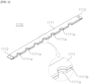
- FIG 1 shows an example of a conventional heat pipe heat exchanger 1.
- a high temperature gas HT is flowed into a high temperature chamber 4a of a high temperature portion 4 to heat a heat pipe 2, and then discharged to the outside.
- a low temperature fluid LT passing through a low temperature chamber 3a of a low temperature portion 3 installed above the high temperature portion 4 exchanges heat with the heat pipe 2 and is then discharged to the outside of the low temperature chamber 3a.
- a separation plate 5 is installed between the high temperature portion 4 and the low temperature portion 3.
- a coupling portion 2b is formed in the middle of the heat pipe 2 and is screwed to the separation plate 5.
- the heat pipe 2 couples heat radiation fins 2a to expand a heat exchange area.
- the heat pipe 2 has to be inserted into the separation plate 5 from the high temperature part 4 side to the low temperature part 3 side or from the low temperature part 3 side to the high temperature part 4 side. For this reason, the heat radiation fins 2a cannot be coupled to a portion of the heat pipe 2 which is inserted and the heat radiation fins 2a can be coupled to only a portion thereof which is not inserted.
- the heat radiation fins 2a for expanding the heat exchange area can be formed on only one selected side of the low temperature portion side and the high temperature portion side, and consequently, there is a problem that the heat exchange efficiency is reduced.
- Korean Patent Laid-Open Publication No. 10-2016-0138720 (title of the invention: modular heat exchanger) can be exemplified.
- the present invention has been created to solve the above problems, and an object of the present invention is to provide a heat pipe heat exchanger implemented to improve heat exchange performance by coupling heat radiation fins for expanding a heat exchange area of a heat pipe to both sides of a high temperature portion and a low temperature portion.
- a heat pipe heat exchanger of the present invention includes a high temperature portion formed with a high temperature chamber through which a high temperature fluid flows in and out; a low temperature portion formed with a low temperature chamber through which a low temperature fluid flows in and out; a separation plate installed between the high temperature portion and the low temperature portion to partition the high temperature portion and the low temperature portion; and a plurality of heat exchange units installed to pass through the separation plate and transferring heat from the high temperature portion to the low temperature portion for heat exchange, in which the separating plate includes a pair of first separation portions spaced apart from each other, a plurality of second separation portions disposed between the pair of first separation plates, and a pair of guide rails that slidably support both ends of the first and second separation portions, and are spaced apart from each other, and the plurality of heat exchange portions are inserted and fixed between the first separation portion and the second separation portion, and between the second separation portions adjacent to each other.
- the heat exchange unit may include a heat pipe, a high temperature radiation fin disposed in the high temperature portion and coupled to an outer circumferential surface of the heat pipe to expand a heat exchange area, and a low temperature radiation fin disposed in the low temperature portion and coupled to the outer circumferential surface of the heat pipe to expand a heat exchange area.
- the pair of first separation portions may be formed with a plurality of semicircular first insertion grooves into which the heat pipes are inserted
- the plurality of second separation portions may be formed with a plurality of semicircular second insertion grooves into which the heat pipes are inserted, side by side on both sides in a width direction
- the heat pipe may be inserted and fixed between the first insertion groove and the second insertion groove, and between the second insertion grooves adjacent to each other.
- the second insertion grooves are disposed to be staggered from each other rather than side by side along the width direction.
- a portion exposed between the high temperature radiation fin and the low temperature radiation fin may be inserted and fixed between the first insertion groove and the second insertion groove, and between the second insertion grooves adjacent to each other.
- a guide groove may be formed for guiding ends of the first separation portion and the second separation portion to slide.
- the first separation portion may include a first plate in which the plurality of first insertion grooves are formed, and a pair of first slide portions respectively protruding from both ends of the first plate and slidably installed in the guide groove.
- the first slide portion and the guide rail may be coupled by bolt.
- the second separation portion may include a second plate on which the plurality of second insertion grooves are formed, and a pair of second slide portions respectively protruding from both ends of the second plate and slidably installed in the guide groove.
- the second slide portion and the guide rail may be coupled by bolt.
- the heat pipe heat exchanger of the present invention described above may further include a plurality of sealing members interposed between the first and second separation portions, and the heat exchange unit to maintain airtightness between the low temperature portion and the high temperature portion, in which in the first and second separation portions, sealing grooves into which the sealing member is inserted may be respectively formed on an insertion surface of the heat exchange unit.
- the sealing member may be a line O-ring.
- the separation plate and the heat pipe can be easily coupled. In this way, the heat exchange efficiency can be improved by expanding the heat exchange area to both the high temperature portion and the low temperature portion of the heat pipe.
- FIG 3 is a perspective view of coupling of a heat pipe heat exchanger according to an example of the present invention
- FIG 4 is a plan view of FIG 3 .
- a heat pipe heat exchanger 1000 of the present invention includes a high temperature portion H, a low temperature portion L, a separation plate 1100, and a heat exchange portion 1200.
- a high temperature chamber HR is formed in the high temperature portion H, and a high temperature fluid HT such as hot gas flows in and out of the high temperature chamber HR.
- a low temperature chamber LR is formed in the low temperature portion L, and a low temperature fluid LT such as water flows in and out of the low temperature chamber LR.
- the separation plate 1100 is installed between the high temperature portion H and the low temperature portion L to separate and partition the high temperature portion H and the low temperature portion L.
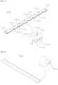
- FIG 5 is a perspective view showing such a heat exchange unit 1200.
- the heat exchange unit 1200 includes a heat pipe 1210, high temperature radiation fins 1230 disposed in the high temperature portion H, and low temperature radiation fins 1220 disposed in the low temperature portion L.
- the heat pipe 1210 is generally made by vacuuming an inside of a metal pipe and adding a small amount of refrigerant.
- the refrigerant typically water
- the refrigerant is determined according to a temperature to be used, and the refrigerant.
- a metal usually copper
- the refrigerant in the heat pipe 1210 convects both ends of the heat pipe 1210 while holding the heat, thereby transferring heat.
- the high temperature radiation fins 1230 and the low temperature radiation fins 1220 are coupled to an outer circumferential surface of the heat pipe 1210 to expand a heat exchange area.
- the high temperature radiation fins 1230 and the low temperature radiation fins 1220 may be made into an annular shape as shown, but this is exemplary and does not limit the shape thereof.
- the separation plate 1100 partitioning the high temperature portion H and the low temperature portion L will be described in detail with reference to the drawings, and an assembling process of the separation plate 1100 and the heat exchange portion 1200 will be described.
- FIG 6 is a perspective view showing a first separation portion 1110 of the separation plate 1100 shown in FIG 3
- FIG 7 is a perspective view showing a second separation portion 1120 of the separation plate 1100 shown in FIG 3
- FIG 8 is a perspective view showing a guide rail 1130 of the separation plate 1100 shown in FIG 3
- FIGS. 9 to 13 are perspective views sequentially explaining for the assembling process of the heat exchange unit 1200 and the separation plate 1100 in the heat pipe heat exchanger 1000 shown in FIG 3 .
- the separation plate 1100 includes a pair of first separation portions 1110, a plurality of second separation portions 1120, and a pair of guide rails 1130.
- the pair of first separation plates 1110 are spaced apart from each other.
- Each of the first separation plates 1110 may include a first plate 1111 on which a plurality of first insertion grooves 1111a are formed, and a pair of first slide portions 1112 protruding from both ends of the first plate 1111, respectively.
- the first insertion grooves 1111a have a semicircular shape and one side of the heat pipe 1210 is inserted thereto.
- each of the second separation plates 1120 may include a second plate 1121 having a plurality of second insertion grooves 1121a formed thereon, and a pair of second slide portions 1121a protruding from both ends of the second plate 1121, respectively.
- the second insertion grooves 1121a have a semicircular shape and the other side of the heat pipe 1210 is inserted thereto.
- these second insertion grooves 1121a are formed side by side on both sides in a width direction.
- the pair of guide rails 1130 are spaced apart from each other to slidably support both ends of the first and second separation plates 1110 and 1120.
- guide grooves 1130a are formed to slidably guide both ends of the first and second separation plates 1110 and 1120. That is, the first slide portion 1112 of the first separation portion 1110 and the second slide portion 1122 of the second separation portion 1120 slide along the guide groove 1130a.
- the heat exchange unit 1200 is inserted and fixed between the first insertion groove 1111a and the second insertion groove 1121a, and between the second insertion grooves 1121a adjacent to each other. More specifically, an exposed portion of the heat pipe 1210 is inserted and fixed between the high temperature radiation fin 1230 and the low temperature radiation fin 1220 in the heat exchange unit 1200.
- the first insertion groove 1111a and the second insertion groove 1121a have to be formed at positions corresponding to each other.
- the second insertion grooves 1121a are not parallel to each other in the width direction, but are staggered from each other. Accordingly, the heat exchange unit 1200 is evenly distributed throughout the high temperature chamber HR and the low temperature chamber LR, so that overall heat exchange efficiency can be improved.
- a sealing member 1300 may be intervened between the first separation portion 1110, the second separation portion 1120, and the heat exchange unit 1200.
- sealing grooves 1111b and 1121b into which the sealing members 1300 are inserted may be respectively formed on an insertion surface of the heat exchange unit 1200.
- a line O-ring may be used as the sealing member 1300, but its structure or material is not limited.
- the first separation portion 1110 is fixedly installed to the pair of guide rails 1130.
- the first slide portion 1112 of the first separation portion 1110 is slid along the guide groove 1130a of the guide rail 1130.
- the first slide portion 1112 and the guide rail 1130 are fixed.
- the first slide portion 1112 and the guide rail 1130 may be fixed by bolt coupling, but this is exemplary and may be fixed through other fastening methods.
- the sealing member 1300 such as a line O-ring is inserted into the sealing groove 1111b of the first separation portion 1110.
- one side surface of a portion of the heat pipe 1210 exposed between the high temperature radiation fin 1230 and the low temperature radiation fin 1220 is inserted into the first insertion groove 1111a of the first separation portion 1110.
- the second slide portion 1122 of the second separation portion 1120 in which the sealing member 1300 is inserted into the sealing groove 1121b is slid into the guide groove 1130a of the guide rail 1130. Accordingly, the other surface of the heat pipe 1210, one side of which is inserted into the first insertion groove 1111a of the first separation portion 1110, is inserted into the second insertion groove 1121a formed on one side of the second separation portion 1120.
- the second slide portion 1122 and the guide rail 1130 are fixed.
- the second slide portion 1122 and the guide rail 1130 may be fixed by bolt coupling, but the fixing method is not limited.
- the sealing member 1300 is inserted into the sealing groove 1121b of the second separation portion 1120. Then, one side of other heat pipes 1210 is inserted into the second insertion groove 1121a formed on the other side of the second separation portion 1120.
- the second slide portion 1122 of the second separation portion 1120 in which the sealing member 1300 is inserted into the sealing groove 1121b is slid into the guide groove 1130a of the guide rail 1130. Accordingly, the other side of the heat pipe 1210 inserted into the second insertion groove 1121a of the second separation portion 1120 adjacent to one side thereof is inserted. In a state where the heat pipes 1210 are inserted into the second insertion grooves 1121a of the adjacent second separation plates 1120 as described above, they are fixed to the guide rails 1130 using bolts or the like.
- the heat pipe heat exchanger 1000 of the present invention since the first and second separation portions 1110 and 1120 that can be separated and coupled to each other in order to separate the high temperature portion H and the low temperature portion L, even if the heat radiation fins 1220 and 1230 for expanding the heat exchange area are coupled to both the high temperature portion H and the low temperature portion L of the heat pipe 1210, the separation plate 1100 and the heat pipe 1210 can be easily coupled. In this way, the heat exchange efficiency can be improved by expanding the heat exchange area to both the high temperature portion and the low temperature portion of the heat pipe 1210.
Applications Claiming Priority (2)
| Application Number | Priority Date | Filing Date | Title |
|---|---|---|---|
| KR1020210174762A KR20230086286A (ko) | 2021-12-08 | 2021-12-08 | 히트파이프 열교환기 |
| PCT/KR2022/017312 WO2023106647A1 (ko) | 2021-12-08 | 2022-11-07 | 히트파이프 열교환기 |
Publications (1)
| Publication Number | Publication Date |
|---|---|
| EP4215859A1 true EP4215859A1 (de) | 2023-07-26 |
Family
ID=86730653
Family Applications (1)
| Application Number | Title | Priority Date | Filing Date |
|---|---|---|---|
| EP22877346.1A Pending EP4215859A1 (de) | 2021-12-08 | 2022-11-07 | Wärmerohr-wärmetauscher |
Country Status (3)
| Country | Link |
|---|---|
| EP (1) | EP4215859A1 (de) |
| KR (1) | KR20230086286A (de) |
| WO (1) | WO2023106647A1 (de) |
Family Cites Families (6)
| Publication number | Priority date | Publication date | Assignee | Title |
|---|---|---|---|---|
| US4098326A (en) * | 1976-09-30 | 1978-07-04 | Mcdonnell Douglas Corporation | Heat exchanger gas separator |
| JP3919998B2 (ja) * | 2000-02-21 | 2007-05-30 | 東芝三菱電機産業システム株式会社 | 熱交換装置の製造方法 |
| JP2002188894A (ja) * | 2000-12-19 | 2002-07-05 | Fujine Sangyo:Kk | ヒートパイプ式熱交換器およびその製造方法 |
| JP2006308111A (ja) * | 2005-04-26 | 2006-11-09 | Showa Denko Kk | ヒートパイプ式熱交換器の製造方法 |
| KR20150080255A (ko) * | 2013-12-31 | 2015-07-09 | 갑을오토텍(주) | 열전소자를 이용한 열교환기 |
| KR20160138720A (ko) | 2015-05-26 | 2016-12-06 | 고범진 | 모듈형 열교환기 |
-
2021
- 2021-12-08 KR KR1020210174762A patent/KR20230086286A/ko not_active IP Right Cessation
-
2022
- 2022-11-07 EP EP22877346.1A patent/EP4215859A1/de active Pending
- 2022-11-07 WO PCT/KR2022/017312 patent/WO2023106647A1/ko unknown
Also Published As
| Publication number | Publication date |
|---|---|
| WO2023106647A1 (ko) | 2023-06-15 |
| KR20230086286A (ko) | 2023-06-15 |
Similar Documents
| Publication | Publication Date | Title |
|---|---|---|
| JP2007515613A (ja) | 複合流体熱交換器及びそれの製造方法 | |
| EP2896923B1 (de) | Wärmetauscher | |
| CN103221773B (zh) | 热交换器组件和方法 | |
| MX2007009246A (es) | Insercion de tubo y disposicion de doble flujo para un colector de una bomba de calor. | |
| EP2767788A1 (de) | Multi-Fluid Wärmetauscher | |
| CA2469733C (en) | Heat exchanger having non-perpendicularly aligned heat transfer elements | |
| EP3458789A1 (de) | Doppelrohr für einen wärmetauscher | |
| US20100294460A1 (en) | Device for cooling a coolant | |
| EP4215859A1 (de) | Wärmerohr-wärmetauscher | |
| CN113383205B (zh) | 换热器 | |
| KR20050061454A (ko) | 편평관 및 편평관을 이용하여 열 교환기를 제조하기 위한프로세스 | |
| EP3572743B1 (de) | Wärmetauscherbaugruppe | |
| EP2515064B1 (de) | Wärmetauscher | |
| KR100740698B1 (ko) | 열교환기용 헤더파이프 | |
| KR20190075679A (ko) | 쉘앤플레이트 열교환기용 쉘 및 이를 구비한 쉘앤플레이트 열교환기 | |
| KR102533346B1 (ko) | 일체형 열교환기 | |
| KR102123760B1 (ko) | 구획 관체가 구비되어 열교환 성능이 개선된 열교환기 | |
| KR102350040B1 (ko) | 열교환기용 튜브 및 이를 포함하는 열교환기 | |
| KR102222507B1 (ko) | 열교환기 | |
| CN219776416U (zh) | 一种多通道换热装置 | |
| CN219677372U (zh) | 一种换热装置及电池换热系统 | |
| JP2003302190A (ja) | コルゲートフィン型熱交換器 | |
| KR102158387B1 (ko) | 헤더탱크의 결합력을 높인 열교환기 | |
| US20230243593A1 (en) | Heat exchanger | |
| EP4317898A1 (de) | Verteiler |
Legal Events
| Date | Code | Title | Description |
|---|---|---|---|
| STAA | Information on the status of an ep patent application or granted ep patent |
Free format text: STATUS: UNKNOWN |
|
| STAA | Information on the status of an ep patent application or granted ep patent |
Free format text: STATUS: THE INTERNATIONAL PUBLICATION HAS BEEN MADE |
|
| PUAI | Public reference made under article 153(3) epc to a published international application that has entered the european phase |
Free format text: ORIGINAL CODE: 0009012 |
|
| STAA | Information on the status of an ep patent application or granted ep patent |
Free format text: STATUS: REQUEST FOR EXAMINATION WAS MADE |
|
| 17P | Request for examination filed |
Effective date: 20230407 |
|
| AK | Designated contracting states |
Kind code of ref document: A1 Designated state(s): AL AT BE BG CH CY CZ DE DK EE ES FI FR GB GR HR HU IE IS IT LI LT LU LV MC ME MK MT NL NO PL PT RO RS SE SI SK SM TR |