EP4215771A1 - Vehicle wheel bearing device - Google Patents
Vehicle wheel bearing device Download PDFInfo
- Publication number
- EP4215771A1 EP4215771A1 EP21869371.1A EP21869371A EP4215771A1 EP 4215771 A1 EP4215771 A1 EP 4215771A1 EP 21869371 A EP21869371 A EP 21869371A EP 4215771 A1 EP4215771 A1 EP 4215771A1
- Authority
- EP
- European Patent Office
- Prior art keywords
- vehicle wheel
- ring
- bearing device
- seal member
- annular space
- Prior art date
- Legal status (The legal status is an assumption and is not a legal conclusion. Google has not performed a legal analysis and makes no representation as to the accuracy of the status listed.)
- Granted
Links
Images


Classifications
-
- F—MECHANICAL ENGINEERING; LIGHTING; HEATING; WEAPONS; BLASTING
- F16—ENGINEERING ELEMENTS AND UNITS; GENERAL MEASURES FOR PRODUCING AND MAINTAINING EFFECTIVE FUNCTIONING OF MACHINES OR INSTALLATIONS; THERMAL INSULATION IN GENERAL
- F16J—PISTONS; CYLINDERS; SEALINGS
- F16J15/00—Sealings
- F16J15/16—Sealings between relatively-moving surfaces
- F16J15/32—Sealings between relatively-moving surfaces with elastic sealings, e.g. O-rings
- F16J15/3248—Sealings between relatively-moving surfaces with elastic sealings, e.g. O-rings provided with casings or supports
- F16J15/3252—Sealings between relatively-moving surfaces with elastic sealings, e.g. O-rings provided with casings or supports with rigid casings or supports
- F16J15/3256—Sealings between relatively-moving surfaces with elastic sealings, e.g. O-rings provided with casings or supports with rigid casings or supports comprising two casing or support elements, one attached to each surface, e.g. cartridge or cassette seals
-
- B—PERFORMING OPERATIONS; TRANSPORTING
- B60—VEHICLES IN GENERAL
- B60B—VEHICLE WHEELS; CASTORS; AXLES FOR WHEELS OR CASTORS; INCREASING WHEEL ADHESION
- B60B27/00—Hubs
- B60B27/0073—Hubs characterised by sealing means
-
- F—MECHANICAL ENGINEERING; LIGHTING; HEATING; WEAPONS; BLASTING
- F16—ENGINEERING ELEMENTS AND UNITS; GENERAL MEASURES FOR PRODUCING AND MAINTAINING EFFECTIVE FUNCTIONING OF MACHINES OR INSTALLATIONS; THERMAL INSULATION IN GENERAL
- F16C—SHAFTS; FLEXIBLE SHAFTS; ELEMENTS OR CRANKSHAFT MECHANISMS; ROTARY BODIES OTHER THAN GEARING ELEMENTS; BEARINGS
- F16C19/00—Bearings with rolling contact, for exclusively rotary movement
- F16C19/02—Bearings with rolling contact, for exclusively rotary movement with bearing balls essentially of the same size in one or more circular rows
- F16C19/14—Bearings with rolling contact, for exclusively rotary movement with bearing balls essentially of the same size in one or more circular rows for both radial and axial load
- F16C19/18—Bearings with rolling contact, for exclusively rotary movement with bearing balls essentially of the same size in one or more circular rows for both radial and axial load with two or more rows of balls
- F16C19/181—Bearings with rolling contact, for exclusively rotary movement with bearing balls essentially of the same size in one or more circular rows for both radial and axial load with two or more rows of balls with angular contact
- F16C19/182—Bearings with rolling contact, for exclusively rotary movement with bearing balls essentially of the same size in one or more circular rows for both radial and axial load with two or more rows of balls with angular contact in tandem arrangement
-
- F—MECHANICAL ENGINEERING; LIGHTING; HEATING; WEAPONS; BLASTING
- F16—ENGINEERING ELEMENTS AND UNITS; GENERAL MEASURES FOR PRODUCING AND MAINTAINING EFFECTIVE FUNCTIONING OF MACHINES OR INSTALLATIONS; THERMAL INSULATION IN GENERAL
- F16C—SHAFTS; FLEXIBLE SHAFTS; ELEMENTS OR CRANKSHAFT MECHANISMS; ROTARY BODIES OTHER THAN GEARING ELEMENTS; BEARINGS
- F16C19/00—Bearings with rolling contact, for exclusively rotary movement
- F16C19/02—Bearings with rolling contact, for exclusively rotary movement with bearing balls essentially of the same size in one or more circular rows
- F16C19/14—Bearings with rolling contact, for exclusively rotary movement with bearing balls essentially of the same size in one or more circular rows for both radial and axial load
- F16C19/18—Bearings with rolling contact, for exclusively rotary movement with bearing balls essentially of the same size in one or more circular rows for both radial and axial load with two or more rows of balls
- F16C19/181—Bearings with rolling contact, for exclusively rotary movement with bearing balls essentially of the same size in one or more circular rows for both radial and axial load with two or more rows of balls with angular contact
- F16C19/183—Bearings with rolling contact, for exclusively rotary movement with bearing balls essentially of the same size in one or more circular rows for both radial and axial load with two or more rows of balls with angular contact with two rows at opposite angles
- F16C19/184—Bearings with rolling contact, for exclusively rotary movement with bearing balls essentially of the same size in one or more circular rows for both radial and axial load with two or more rows of balls with angular contact with two rows at opposite angles in O-arrangement
- F16C19/186—Bearings with rolling contact, for exclusively rotary movement with bearing balls essentially of the same size in one or more circular rows for both radial and axial load with two or more rows of balls with angular contact with two rows at opposite angles in O-arrangement with three raceways provided integrally on parts other than race rings, e.g. third generation hubs
-
- F—MECHANICAL ENGINEERING; LIGHTING; HEATING; WEAPONS; BLASTING
- F16—ENGINEERING ELEMENTS AND UNITS; GENERAL MEASURES FOR PRODUCING AND MAINTAINING EFFECTIVE FUNCTIONING OF MACHINES OR INSTALLATIONS; THERMAL INSULATION IN GENERAL
- F16C—SHAFTS; FLEXIBLE SHAFTS; ELEMENTS OR CRANKSHAFT MECHANISMS; ROTARY BODIES OTHER THAN GEARING ELEMENTS; BEARINGS
- F16C33/00—Parts of bearings; Special methods for making bearings or parts thereof
- F16C33/72—Sealings
- F16C33/76—Sealings of ball or roller bearings
- F16C33/768—Sealings of ball or roller bearings between relatively stationary parts, i.e. static seals
-
- F—MECHANICAL ENGINEERING; LIGHTING; HEATING; WEAPONS; BLASTING
- F16—ENGINEERING ELEMENTS AND UNITS; GENERAL MEASURES FOR PRODUCING AND MAINTAINING EFFECTIVE FUNCTIONING OF MACHINES OR INSTALLATIONS; THERMAL INSULATION IN GENERAL
- F16C—SHAFTS; FLEXIBLE SHAFTS; ELEMENTS OR CRANKSHAFT MECHANISMS; ROTARY BODIES OTHER THAN GEARING ELEMENTS; BEARINGS
- F16C33/00—Parts of bearings; Special methods for making bearings or parts thereof
- F16C33/72—Sealings
- F16C33/76—Sealings of ball or roller bearings
- F16C33/78—Sealings of ball or roller bearings with a diaphragm, disc, or ring, with or without resilient members
-
- F—MECHANICAL ENGINEERING; LIGHTING; HEATING; WEAPONS; BLASTING
- F16—ENGINEERING ELEMENTS AND UNITS; GENERAL MEASURES FOR PRODUCING AND MAINTAINING EFFECTIVE FUNCTIONING OF MACHINES OR INSTALLATIONS; THERMAL INSULATION IN GENERAL
- F16C—SHAFTS; FLEXIBLE SHAFTS; ELEMENTS OR CRANKSHAFT MECHANISMS; ROTARY BODIES OTHER THAN GEARING ELEMENTS; BEARINGS
- F16C33/00—Parts of bearings; Special methods for making bearings or parts thereof
- F16C33/72—Sealings
- F16C33/76—Sealings of ball or roller bearings
- F16C33/78—Sealings of ball or roller bearings with a diaphragm, disc, or ring, with or without resilient members
- F16C33/7816—Details of the sealing or parts thereof, e.g. geometry, material
- F16C33/783—Details of the sealing or parts thereof, e.g. geometry, material of the mounting region
-
- F—MECHANICAL ENGINEERING; LIGHTING; HEATING; WEAPONS; BLASTING
- F16—ENGINEERING ELEMENTS AND UNITS; GENERAL MEASURES FOR PRODUCING AND MAINTAINING EFFECTIVE FUNCTIONING OF MACHINES OR INSTALLATIONS; THERMAL INSULATION IN GENERAL
- F16C—SHAFTS; FLEXIBLE SHAFTS; ELEMENTS OR CRANKSHAFT MECHANISMS; ROTARY BODIES OTHER THAN GEARING ELEMENTS; BEARINGS
- F16C33/00—Parts of bearings; Special methods for making bearings or parts thereof
- F16C33/72—Sealings
- F16C33/76—Sealings of ball or roller bearings
- F16C33/78—Sealings of ball or roller bearings with a diaphragm, disc, or ring, with or without resilient members
- F16C33/7816—Details of the sealing or parts thereof, e.g. geometry, material
- F16C33/7833—Special methods of manufacture
-
- F—MECHANICAL ENGINEERING; LIGHTING; HEATING; WEAPONS; BLASTING
- F16—ENGINEERING ELEMENTS AND UNITS; GENERAL MEASURES FOR PRODUCING AND MAINTAINING EFFECTIVE FUNCTIONING OF MACHINES OR INSTALLATIONS; THERMAL INSULATION IN GENERAL
- F16C—SHAFTS; FLEXIBLE SHAFTS; ELEMENTS OR CRANKSHAFT MECHANISMS; ROTARY BODIES OTHER THAN GEARING ELEMENTS; BEARINGS
- F16C33/00—Parts of bearings; Special methods for making bearings or parts thereof
- F16C33/72—Sealings
- F16C33/76—Sealings of ball or roller bearings
- F16C33/78—Sealings of ball or roller bearings with a diaphragm, disc, or ring, with or without resilient members
- F16C33/7869—Sealings of ball or roller bearings with a diaphragm, disc, or ring, with or without resilient members mounted with a cylindrical portion to the inner surface of the outer race and having a radial portion extending inward
- F16C33/7873—Sealings of ball or roller bearings with a diaphragm, disc, or ring, with or without resilient members mounted with a cylindrical portion to the inner surface of the outer race and having a radial portion extending inward with a single sealing ring of generally L-shaped cross-section
- F16C33/7876—Sealings of ball or roller bearings with a diaphragm, disc, or ring, with or without resilient members mounted with a cylindrical portion to the inner surface of the outer race and having a radial portion extending inward with a single sealing ring of generally L-shaped cross-section with sealing lips
-
- F—MECHANICAL ENGINEERING; LIGHTING; HEATING; WEAPONS; BLASTING
- F16—ENGINEERING ELEMENTS AND UNITS; GENERAL MEASURES FOR PRODUCING AND MAINTAINING EFFECTIVE FUNCTIONING OF MACHINES OR INSTALLATIONS; THERMAL INSULATION IN GENERAL
- F16C—SHAFTS; FLEXIBLE SHAFTS; ELEMENTS OR CRANKSHAFT MECHANISMS; ROTARY BODIES OTHER THAN GEARING ELEMENTS; BEARINGS
- F16C33/00—Parts of bearings; Special methods for making bearings or parts thereof
- F16C33/72—Sealings
- F16C33/76—Sealings of ball or roller bearings
- F16C33/78—Sealings of ball or roller bearings with a diaphragm, disc, or ring, with or without resilient members
- F16C33/7869—Sealings of ball or roller bearings with a diaphragm, disc, or ring, with or without resilient members mounted with a cylindrical portion to the inner surface of the outer race and having a radial portion extending inward
- F16C33/7879—Sealings of ball or roller bearings with a diaphragm, disc, or ring, with or without resilient members mounted with a cylindrical portion to the inner surface of the outer race and having a radial portion extending inward with a further sealing ring
- F16C33/7883—Sealings of ball or roller bearings with a diaphragm, disc, or ring, with or without resilient members mounted with a cylindrical portion to the inner surface of the outer race and having a radial portion extending inward with a further sealing ring mounted to the inner race and of generally L-shape, the two sealing rings defining a sealing with box-shaped cross-section
-
- F—MECHANICAL ENGINEERING; LIGHTING; HEATING; WEAPONS; BLASTING
- F16—ENGINEERING ELEMENTS AND UNITS; GENERAL MEASURES FOR PRODUCING AND MAINTAINING EFFECTIVE FUNCTIONING OF MACHINES OR INSTALLATIONS; THERMAL INSULATION IN GENERAL
- F16J—PISTONS; CYLINDERS; SEALINGS
- F16J15/00—Sealings
- F16J15/02—Sealings between relatively-stationary surfaces
- F16J15/14—Sealings between relatively-stationary surfaces by means of granular or plastic material, or fluid
-
- F—MECHANICAL ENGINEERING; LIGHTING; HEATING; WEAPONS; BLASTING
- F16—ENGINEERING ELEMENTS AND UNITS; GENERAL MEASURES FOR PRODUCING AND MAINTAINING EFFECTIVE FUNCTIONING OF MACHINES OR INSTALLATIONS; THERMAL INSULATION IN GENERAL
- F16J—PISTONS; CYLINDERS; SEALINGS
- F16J15/00—Sealings
- F16J15/16—Sealings between relatively-moving surfaces
- F16J15/32—Sealings between relatively-moving surfaces with elastic sealings, e.g. O-rings
- F16J15/3204—Sealings between relatively-moving surfaces with elastic sealings, e.g. O-rings with at least one lip
- F16J15/3232—Sealings between relatively-moving surfaces with elastic sealings, e.g. O-rings with at least one lip having two or more lips
-
- F—MECHANICAL ENGINEERING; LIGHTING; HEATING; WEAPONS; BLASTING
- F16—ENGINEERING ELEMENTS AND UNITS; GENERAL MEASURES FOR PRODUCING AND MAINTAINING EFFECTIVE FUNCTIONING OF MACHINES OR INSTALLATIONS; THERMAL INSULATION IN GENERAL
- F16J—PISTONS; CYLINDERS; SEALINGS
- F16J15/00—Sealings
- F16J15/16—Sealings between relatively-moving surfaces
- F16J15/32—Sealings between relatively-moving surfaces with elastic sealings, e.g. O-rings
- F16J15/3268—Mounting of sealing rings
- F16J15/3276—Mounting of sealing rings with additional static sealing between the sealing, or its casing or support, and the surface on which it is mounted
-
- F—MECHANICAL ENGINEERING; LIGHTING; HEATING; WEAPONS; BLASTING
- F16—ENGINEERING ELEMENTS AND UNITS; GENERAL MEASURES FOR PRODUCING AND MAINTAINING EFFECTIVE FUNCTIONING OF MACHINES OR INSTALLATIONS; THERMAL INSULATION IN GENERAL
- F16J—PISTONS; CYLINDERS; SEALINGS
- F16J15/00—Sealings
- F16J15/16—Sealings between relatively-moving surfaces
- F16J15/40—Sealings between relatively-moving surfaces by means of fluid
-
- B—PERFORMING OPERATIONS; TRANSPORTING
- B60—VEHICLES IN GENERAL
- B60B—VEHICLE WHEELS; CASTORS; AXLES FOR WHEELS OR CASTORS; INCREASING WHEEL ADHESION
- B60B27/00—Hubs
- B60B27/0078—Hubs characterised by the fixation of bearings
-
- F—MECHANICAL ENGINEERING; LIGHTING; HEATING; WEAPONS; BLASTING
- F16—ENGINEERING ELEMENTS AND UNITS; GENERAL MEASURES FOR PRODUCING AND MAINTAINING EFFECTIVE FUNCTIONING OF MACHINES OR INSTALLATIONS; THERMAL INSULATION IN GENERAL
- F16C—SHAFTS; FLEXIBLE SHAFTS; ELEMENTS OR CRANKSHAFT MECHANISMS; ROTARY BODIES OTHER THAN GEARING ELEMENTS; BEARINGS
- F16C2326/00—Articles relating to transporting
- F16C2326/01—Parts of vehicles in general
- F16C2326/02—Wheel hubs or castors
Definitions
- the present invention relates to a bearing device for a vehicle wheel.
- a seal member for preventing entry of foreign matter such as muddy water is provided between an outer member and an inner member.
- An outer-side seal member of the bearing device for a vehicle wheel is fitted to an outer-side end portion of the outer member, and closes an outer-side opening end of an annular space formed by the outer member and the inner member.
- Patent Literature 1 JP-B2 4893648 Gazette
- the present invention has been made in view of the above circumstances, and an object of the present invention is to provide a bearing device for a vehicle wheel including an outer-side seal that is resistant to deterioration over time and can prevent foreign matter such as muddy water from penetrating into the interior of a bearing.
- a first invention includes: an outer member which has a plurality of rows of outer raceway surfaces provided on an inner periphery; an inner member which includes a hub ring and at least one inner ring, the hub ring having a small-diameter step portion that is provided on an outer periphery and axially extends and a vehicle wheel mounting flange that is disposed on an outer side with respect to the small-diameter step portion, the at least one inner ring being press-fitted to the small-diameter step portion of the hub ring, the inner member having a plurality of rows of inner raceway surfaces that are provided on an outer periphery and face the plurality of rows of outer raceway surfaces; a plurality of rows of rolling elements that are rollably accommodated between the plurality of rows of inner raceway surfaces of the inner member and the plurality of rows of outer raceway surfaces of the outer member; and an outer-side seal member that closes an outer-side opening end of an annular space formed by the outer member and the inner member, the outer
- the bearing device for a vehicle wheel including the outer-side seal member can be provided in which by filling the annular space between the metal ring and the hub ring with the filler, it is possible to prevent foreign matter such as muddy water from penetrating into the interior of a bearing through the annular space and muddy water resistance is improved.
- an inner side represents the vehicle body side of the bearing device for a vehicle wheel 1 when attached to the vehicle body
- an outer side represents the vehicle wheel side of the bearing device for a vehicle wheel 1 when attached to the vehicle body.
- the bearing device for a vehicle wheel 1 rotatably supports a vehicle wheel in a suspension device of a vehicle such as an automobile.
- the bearing device for a vehicle wheel 1 includes an outer ring 2, a hub ring 3, an inner ring 4, rolling elements 5, an inner-side seal member 6, and an outer-side seal member 7.
- the outer ring 2 which is an outer member, supports the hub ring 3 and the inner ring 4.
- An inner-side opening 2b into which the inner-side seal member 6 can be fitted is formed in an inner-side end portion of the outer ring 2.
- An outer-side opening 2c into which the outer-side seal member 7 can be fitted is formed in an outer-side end portion 2f of the outer ring 2.
- a vehicle body mounting flange 2d for being mounted to a knuckle of the suspension device, not illustrated, is integrally provided on an outer peripheral surface 2e of the outer ring 2.
- On the inner side and the outer side of the inner peripheral surface of the outer ring 2 a plurality of rows of inner raceway surfaces 2a, 2a are provided in the circumferential direction.
- the inner member includes the hub ring 3 and the inner ring 4.
- the hub ring 3 rotatably supports the vehicle wheel of the vehicle, not illustrated.
- a small-diameter step portion 3a whose diameter is reduced is provided on the outer peripheral surface of an inner-side end portion of the hub ring 3.
- a vehicle wheel mounting flange 3b for mounting the vehicle wheel is integrally provided at an outer-side end portion of the hub ring 3.
- a hub bolt 3c for fastening the hub ring 3 and a vehicle wheel or a brake device is press-fitted into the vehicle wheel mounting flange 3b.
- An inner raceway surface 3d is provided on the outer side on the outer peripheral surface of the hub ring 3.
- the flat surface portion 3g is located at the base end portion of the vehicle wheel mounting flange 3b.
- the inner ring 4 is press-fitted to the small-diameter step portion 3a of the hub ring 3.
- An inner raceway surface 4a is provided on the outer peripheral surface of the inner ring 4. That is, the inner ring 4 forms the inner raceway surface 4a on the inner side of the hub ring 3.
- the rolling elements 5 include a plurality of balls and cages that hold the balls, respectively.
- the inner-side seal member 6 includes a substantially cylindrical seal plate 6a and a substantially cylindrical slinger 6b.
- the seal plate 6a is fitted to the inner-side opening 2b of the outer ring 2, and the slinger 6b is fitted to the inner ring 4.
- the outer-side seal member 7 closes the outer-side opening end of the annular space formed by the outer ring 2 and the hub ring 3.
- the outer-side seal member 7 includes a core metal 8, a metal ring 9, a seal member 10, and a sealing material 20.
- the core metal 8 is formed by, for example, pressing a steel plate. As illustrated in FIG. 2 , the core metal 8 includes a cylindrical portion 8a and a bent portion 8b.
- the cylindrical portion 8a is fitted into the outer-side opening 2c of the outer ring 2 (the inner peripheral surface of the outer-side end portion 2f of the outer ring 2).
- the bent portion 8b is bent from the outer-side end portion of the cylindrical portion 8a and extends radially inward.
- the seal member 10 made of, for example, synthetic rubber is joined (here, vulcanized-bonded) to the core metal 8.
- a radial lip 10a, an inner axial lip 10b, and an outer axial lip 10c of the seal member 10 are joined to the bent portion 8b.
- the radial lip 10a is provided on the radially innermost side of the bent portion 8b.
- the radial lip 10a prevents grease inside the bearing device for a vehicle wheel 1 from leaking to the outside.
- the inner axial lip 10b is provided radially outside the radial lip 10a.
- the outer axial lip 10c is provided radially outside the inner axial lip 10b.
- the metal ring 9 is formed by, for example, pressing a steel plate.
- the metal ring 9 includes a cylindrical portion 9a, a curved portion 9b, a disk portion 9c, a tapered portion 9d, and a flange portion 9e.
- the cylindrical portion 9a is fitted to the shoulder portion 3e (portion adjacent to the inner peripheral raceway surface 3d on the outer side) of the hub ring 3.
- the radial lip 10a is in sliding contact with the cylindrical portion 9a via a grease oil film.
- the curved portion 9b has a substantially arc shape in a cross-sectional view, and increases in diameter radially outward from the outer-side end portion of the cylindrical portion 9a toward the outer side.
- the inner axial lip 10b is in sliding contact with the curved portion 9b via the grease oil film.
- the disk portion 9c extends radially outward from a front end portion of the curved portion 9b.
- the outer axial lip 10c is in sliding contact with the disk portion 9c via the grease oil film.
- the disk portion 9c faces the flat surface portion 3g of the hub ring 3.
- the curved portion 9b is a portion between a portion of the metal ring 9 fitted to the hub ring 3 and a portion of the metal ring 9 facing the vehicle wheel mounting flange 3b.
- the curved portion 9b of the metal ring 9 is provided to improve rigidity of the metal ring 9.
- rigidity of the metal ring 9 can be improved, and movement of the metal ring 9 when a turning load of the vehicle is applied can be suppressed.
- the tapered portion 9d increases in diameter from the outer peripheral edge of the disk portion 9c toward the inner side.
- the flange portion 9e extends radially outward from the front end portion of the tapered portion 9d.
- the hub ring 3 has the curved surface portion 3f which faces the curved portion 9b of the metal ring 9 and is an outer peripheral surface having a substantially arc shape in a cross-sectional view.
- the curved surface portion 3f is formed over the entire circumference of the hub ring 3.
- the curved surface portion 3f increases in diameter radially outward from the outer-side end of the shoulder portion 3e of the hub ring 3 toward the outer side.
- An annular space S having a substantially crescent shape in a cross-sectional view is provided between the curved portion 9b and the curved surface portion 3f.
- the annular space S is filled with the sealing material 20, which is an example of a filler.
- the sealing material 20 is a material that is applied to a space (gap) portion of a structure to exhibit functions such as waterproofness and airtightness.
- the sealing material 20 of the present embodiment is held in a gel state (paste state). That is, the sealing material 20 of the present embodiment is not cured.
- the sealing material 20 has predetermined viscosity.
- the sealing material 20 is applied annularly along the circumferential direction of the annular curved surface portion 3f of the hub ring 3 by using a coating device, and the outer-side seal member 7 is assembled to the hub ring 3 to which the sealing material 20 is applied, and therefore the applied sealing material 20 spreads and is filled in the annular space S.
- the annular space S is sealed by the sealing material 20.
- the upper limit value is an amount of filling 100% of the volume of the annular space S, that is, the space volume between the hub ring 3 (curved surface portion 3f) and the metal ring 9 (curved portion 9b) with the sealing material 20 (amount that does not protrude to the outside of the annular space S), and the lower limit value is an amount by which the sealing material 20 is uniformly applied at least to the fitting portion between the hub ring 3 and the metal ring 9 without any gap.
- the sealing material 20 can exhibit functions such as waterproofness and airtightness.
- the annular space S is provided between the curved portion 9b of the metal ring 9 and the curved surface portion 3f of the hub ring 3, and the sealing material 20 is filled in the annular space S.
- the annular space S As a result, it is possible to prevent foreign matter such as muddy water from penetrating into the interior of the bearing through the annular space S and to improve muddy water resistance. That is, since a conventional bearing device for a vehicle wheel has an annular space S as illustrated in FIG. 5 , there is a possibility that foreign matter such as muddy water accumulates in the annular space S and the foreign matter such as muddy water intrudes into the interior of a bearing.
- the sealing material 20 since the annular space S is sealed by the sealing material 20, it is possible to suppress accumulation of foreign matter such as muddy water in the annular space S and to prevent the foreign matter such as muddy water from penetrating into the interior of the bearing. That is, the sealing material 20 functions to close the annular space S, which is one of the paths through which foreign matter such as muddy water enters. In addition, since the sealing material 20 of the present embodiment is held in a gel state (paste state) without being cured, degradation over time such as cracking due to curing is suppressed.
- the outer-side seal member 7 of the bearing device for a vehicle wheel 1 is not provided with a rubber member unlike the conventional bearing device for a vehicle wheel illustrated in FIG. 5 . Therefore, in the bearing device for a vehicle wheel 1, it is not necessary to provide a region for arranging a rubber member in the flat surface portion 3g that is the surface in contact with the metal ring 9 (disk portion 9c) in the hub ring 3, and the outer-side seal member can be downsized.
- the outer-side seal member 7 of the bearing device for a vehicle wheel 1 is not provided with a rubber member, there is an advantage that no design restriction is imposed even in a case where the outer-side seal member and a peripheral component such as a head portion of a hub bolt are close to each other. Furthermore, since the outer-side seal member 7 of the bearing device for a vehicle wheel 1 is not provided with a rubber member, the cost can be reduced.
- the bearing device for a vehicle wheel 1A is a modification of the first embodiment, and a rubber member 11 is added to the outer-side seal member 7 of the bearing device for a vehicle wheel 1 according to the first embodiment.
- the rubber member 11 is joined (here, vulcanized-bonded) to surfaces of a disk portion 9c, a tapered portion 9d, and a flange portion 9e which face a flat surface portion 3g of a hub ring 3 in the axial direction.
- the rubber member 11 is, for example, synthetic rubber.
- the rubber member 11 is provided radially outside a metal ring 9 and is in contact with the flat surface portion 3g of the hub ring 3.
- the bearing device for a vehicle wheel 1A has the effect similar to that of the bearing device for a vehicle wheel 1 of the first embodiment, and since the rubber member 11 is provided, it is possible to further suppress foreign matter such as muddy water from penetrating into the interior of a bearing.
- the bearing device for a vehicle wheel 1B is a modification of the first embodiment, and includes a folded portion 9b1 in lieu of the curved portion 9b in the bearing device for a vehicle wheel 1 according to the first embodiment.
- the folded portion 9b1 has a linear shape in a cross-sectional view, and increases in diameter radially outward from the outer-side end portion of a cylindrical portion 9a toward the outer side.
- the folded portion 9b1 is a portion between a portion of a metal ring 9 fitted to a hub ring 3 and a portion of the metal ring 9 facing a vehicle wheel mounting flange 3b.
- An annular space S1 having a substantially semi-elliptical shape in a cross-sectional view is provided between the folded portion 9b1 and a curved surface portion 3f.
- the annular space S1 is filled with a sealing material 20.
- the bearing device for a vehicle wheel 1B has the effect similar to that of the bearing device for a vehicle wheel 1 of the first embodiment.
- the annular space S1 becomes larger; however, the annular space S1 can be easily sealed by filling the annular space S1 with the sealing material 20, which is a filler. As a result, muddy water resistance is further improved.
- a rubber member 11 may be added to the bearing device for a vehicle wheel 1B as in the bearing device for a vehicle wheel 1A of the second embodiment.
- each of the bearing devices for a vehicle wheel 1, 1A, and 1B according to the present embodiments has been described as a bearing device for a vehicle wheel having a third-generation structure in which the inner raceway surface 3d of the rolling elements 5 is directly formed on the outer periphery of the hub ring 3.
- each of the bearing devices for a vehicle wheel 1, 1A, and 1B is not limited to this, and for example, may have a second-generation structure of inner ring rotation in which a pair of inner rings 4 is press-fitted and fixed to the hub ring 3.
- the above-described embodiments are merely representative forms of the present invention, and various modifications can be made without departing from the gist of the present invention.
- the present invention is applicable to a bearing device for a vehicle wheel.
Landscapes
- Engineering & Computer Science (AREA)
- General Engineering & Computer Science (AREA)
- Mechanical Engineering (AREA)
- Rolling Contact Bearings (AREA)
- Sealing Using Fluids, Sealing Without Contact, And Removal Of Oil (AREA)
- Sealing Devices (AREA)
- Sealing Of Bearings (AREA)
- Sealing With Elastic Sealing Lips (AREA)
Abstract
Description
- The present invention relates to a bearing device for a vehicle wheel.
- In a bearing device for a vehicle wheel, a seal member for preventing entry of foreign matter such as muddy water is provided between an outer member and an inner member. An outer-side seal member of the bearing device for a vehicle wheel is fitted to an outer-side end portion of the outer member, and closes an outer-side opening end of an annular space formed by the outer member and the inner member.
- There is a bearing device for a vehicle wheel in which a seal structure of a seal member is devised to ensure sealability (See, for example, Patent Literature 1).
- In the bearing device for a vehicle wheel disclosed in
Patent Literature 1, a gap existing between a curved surface portion of a slinger and a peripheral surface of a rotating-side bearing ring is filled with an adhesive having oil surface adhesiveness over the entire circumference. Thus, sealability of the fitting portion between the slinger and the rotating-side bearing ring is secured. - However, in such a conventional seal structure, in a case where the adhesive cured due to degradation over time or the like is cracked, sealability may be deteriorated. Therefore, there is a demand for a seal member that is resistant to deterioration over time and is capable of preventing entry of foreign matter such as muddy water.
- Patent Literature 1:
JP-B2 4893648 - The present invention has been made in view of the above circumstances, and an object of the present invention is to provide a bearing device for a vehicle wheel including an outer-side seal that is resistant to deterioration over time and can prevent foreign matter such as muddy water from penetrating into the interior of a bearing.
- A first invention includes: an outer member which has a plurality of rows of outer raceway surfaces provided on an inner periphery; an inner member which includes a hub ring and at least one inner ring, the hub ring having a small-diameter step portion that is provided on an outer periphery and axially extends and a vehicle wheel mounting flange that is disposed on an outer side with respect to the small-diameter step portion, the at least one inner ring being press-fitted to the small-diameter step portion of the hub ring, the inner member having a plurality of rows of inner raceway surfaces that are provided on an outer periphery and face the plurality of rows of outer raceway surfaces; a plurality of rows of rolling elements that are rollably accommodated between the plurality of rows of inner raceway surfaces of the inner member and the plurality of rows of outer raceway surfaces of the outer member; and an outer-side seal member that closes an outer-side opening end of an annular space formed by the outer member and the inner member, the outer-side seal member including a core metal which is fitted to the outer member, a seal member which is joined to the core metal, and a metal ring which is fitted to the hub ring of the inner member and with which the seal member is in sliding contact, and an annular space being provided between the metal ring and the hub ring, and the annular space being filled with a filler.
- According to the present invention, the bearing device for a vehicle wheel including the outer-side seal member can be provided in which by filling the annular space between the metal ring and the hub ring with the filler, it is possible to prevent foreign matter such as muddy water from penetrating into the interior of a bearing through the annular space and muddy water resistance is improved.
-
-
FIG. 1 is a cross-sectional view illustrating an overall configuration of a bearing device for a vehicle wheel according to a first embodiment. -
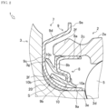
FIG. 2 is an enlarged cross-sectional view illustrating an outer-side seal member of the bearing device for a vehicle wheel according to the first embodiment. -
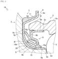
FIG. 3 is an enlarged cross-sectional view illustrating an outer-side seal member of a bearing device for a vehicle wheel according to a second embodiment. -
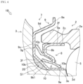
FIG. 4 is an enlarged cross-sectional view illustrating an outer-side seal member of a bearing device for a vehicle wheel according to a third embodiment. -
FIG. 5 is an enlarged cross-sectional view illustrating an outer-side seal member of a conventional bearing device for a vehicle wheel. - Hereinafter, a bearing device for a
vehicle wheel 1 as a first embodiment of a bearing device for a vehicle wheel will be described with reference toFIGS. 1 and2 . Note that in the following description, an inner side represents the vehicle body side of the bearing device for avehicle wheel 1 when attached to the vehicle body, and an outer side represents the vehicle wheel side of the bearing device for avehicle wheel 1 when attached to the vehicle body. - As illustrated in
FIG. 1 , the bearing device for avehicle wheel 1 rotatably supports a vehicle wheel in a suspension device of a vehicle such as an automobile. The bearing device for avehicle wheel 1 includes anouter ring 2, ahub ring 3, aninner ring 4,rolling elements 5, an inner-side seal member 6, and an outer-side seal member 7. - As illustrated in
FIG. 1 , theouter ring 2, which is an outer member, supports thehub ring 3 and theinner ring 4. An inner-side opening 2b into which the inner-side seal member 6 can be fitted is formed in an inner-side end portion of theouter ring 2. An outer-side opening 2c into which the outer-side seal member 7 can be fitted is formed in an outer-side end portion 2f of theouter ring 2. A vehiclebody mounting flange 2d for being mounted to a knuckle of the suspension device, not illustrated, is integrally provided on an outerperipheral surface 2e of theouter ring 2. On the inner side and the outer side of the inner peripheral surface of theouter ring 2, a plurality of rows ofinner raceway surfaces - The inner member includes the
hub ring 3 and theinner ring 4. Thehub ring 3 rotatably supports the vehicle wheel of the vehicle, not illustrated. A small-diameter step portion 3a whose diameter is reduced is provided on the outer peripheral surface of an inner-side end portion of thehub ring 3. A vehiclewheel mounting flange 3b for mounting the vehicle wheel is integrally provided at an outer-side end portion of thehub ring 3. Ahub bolt 3c for fastening thehub ring 3 and a vehicle wheel or a brake device is press-fitted into the vehiclewheel mounting flange 3b. Aninner raceway surface 3d is provided on the outer side on the outer peripheral surface of thehub ring 3. Ashoulder portion 3e, acurved surface portion 3f, and aflat surface portion 3g, which are portions where the outer-side seal member 7 is disposed, are continuously provided on the outer side with respect to theinner raceway surface 3d on the outer peripheral surface (seeFIG. 2 and the like). Theflat surface portion 3g is located at the base end portion of the vehiclewheel mounting flange 3b. - The
inner ring 4 is press-fitted to the small-diameter step portion 3a of thehub ring 3. Aninner raceway surface 4a is provided on the outer peripheral surface of theinner ring 4. That is, theinner ring 4 forms theinner raceway surface 4a on the inner side of thehub ring 3. - The
rolling elements 5 include a plurality of balls and cages that hold the balls, respectively. - The inner-side seal member 6 includes a substantially
cylindrical seal plate 6a and a substantiallycylindrical slinger 6b. Theseal plate 6a is fitted to the inner-side opening 2b of theouter ring 2, and theslinger 6b is fitted to theinner ring 4. - As illustrated in
FIGS. 1 and2 , the outer-side seal member 7 closes the outer-side opening end of the annular space formed by theouter ring 2 and thehub ring 3. The outer-side seal member 7 includes a core metal 8, ametal ring 9, aseal member 10, and asealing material 20. - The core metal 8 is formed by, for example, pressing a steel plate. As illustrated in
FIG. 2 , the core metal 8 includes acylindrical portion 8a and abent portion 8b. - The
cylindrical portion 8a is fitted into the outer-side opening 2c of the outer ring 2 (the inner peripheral surface of the outer-side end portion 2f of the outer ring 2). Thebent portion 8b is bent from the outer-side end portion of thecylindrical portion 8a and extends radially inward. - The
seal member 10 made of, for example, synthetic rubber is joined (here, vulcanized-bonded) to the core metal 8. Aradial lip 10a, an inneraxial lip 10b, and an outeraxial lip 10c of theseal member 10 are joined to thebent portion 8b. Theradial lip 10a is provided on the radially innermost side of thebent portion 8b. Theradial lip 10a prevents grease inside the bearing device for avehicle wheel 1 from leaking to the outside. The inneraxial lip 10b is provided radially outside theradial lip 10a. The outeraxial lip 10c is provided radially outside the inneraxial lip 10b. - The
metal ring 9 is formed by, for example, pressing a steel plate. Themetal ring 9 includes acylindrical portion 9a, acurved portion 9b, adisk portion 9c, atapered portion 9d, and aflange portion 9e. - The
cylindrical portion 9a is fitted to theshoulder portion 3e (portion adjacent to the innerperipheral raceway surface 3d on the outer side) of thehub ring 3. Theradial lip 10a is in sliding contact with thecylindrical portion 9a via a grease oil film. Thecurved portion 9b has a substantially arc shape in a cross-sectional view, and increases in diameter radially outward from the outer-side end portion of thecylindrical portion 9a toward the outer side. The inneraxial lip 10b is in sliding contact with thecurved portion 9b via the grease oil film. Thedisk portion 9c extends radially outward from a front end portion of thecurved portion 9b. The outeraxial lip 10c is in sliding contact with thedisk portion 9c via the grease oil film. Thedisk portion 9c faces theflat surface portion 3g of thehub ring 3. Note that thecurved portion 9b is a portion between a portion of themetal ring 9 fitted to thehub ring 3 and a portion of themetal ring 9 facing the vehiclewheel mounting flange 3b. - The
curved portion 9b of themetal ring 9 is provided to improve rigidity of themetal ring 9. By providing thecurved portion 9b, rigidity of themetal ring 9 can be improved, and movement of themetal ring 9 when a turning load of the vehicle is applied can be suppressed. - The tapered
portion 9d increases in diameter from the outer peripheral edge of thedisk portion 9c toward the inner side. Theflange portion 9e extends radially outward from the front end portion of the taperedportion 9d. - The
hub ring 3 has thecurved surface portion 3f which faces thecurved portion 9b of themetal ring 9 and is an outer peripheral surface having a substantially arc shape in a cross-sectional view. Thecurved surface portion 3f is formed over the entire circumference of thehub ring 3. Thecurved surface portion 3f increases in diameter radially outward from the outer-side end of theshoulder portion 3e of thehub ring 3 toward the outer side. An annular space S having a substantially crescent shape in a cross-sectional view is provided between thecurved portion 9b and thecurved surface portion 3f. The annular space S is filled with the sealingmaterial 20, which is an example of a filler. The sealingmaterial 20 is a material that is applied to a space (gap) portion of a structure to exhibit functions such as waterproofness and airtightness. The sealingmaterial 20 of the present embodiment is held in a gel state (paste state). That is, the sealingmaterial 20 of the present embodiment is not cured. The sealingmaterial 20 has predetermined viscosity. As the sealingmaterial 20, there are various choices from an acrylic-based sealing material, a urethane-based sealing material, a polyurethane-based sealing material, a silicon-based sealing material, a modified silicon sealing material, an oily coking-based sealing material, a polysulfide-based sealing material, a butyl rubber-based sealing material, and the like. - As a method of filling the annular space S with the sealing
material 20, for example, before the outer-side seal member 7 is assembled to thehub ring 3, the sealingmaterial 20 is applied annularly along the circumferential direction of the annularcurved surface portion 3f of thehub ring 3 by using a coating device, and the outer-side seal member 7 is assembled to thehub ring 3 to which the sealingmaterial 20 is applied, and therefore the applied sealingmaterial 20 spreads and is filled in the annular space S. Thus, the annular space S is sealed by the sealingmaterial 20. - In addition, with respect to the filling amount of the sealing
material 20 into the annular space S, the upper limit value is an amount of filling 100% of the volume of the annular space S, that is, the space volume between the hub ring 3 (curved surface portion 3f) and the metal ring 9 (curved portion 9b) with the sealing material 20 (amount that does not protrude to the outside of the annular space S), and the lower limit value is an amount by which the sealingmaterial 20 is uniformly applied at least to the fitting portion between thehub ring 3 and themetal ring 9 without any gap. Within such a filling amount range, the sealingmaterial 20 can exhibit functions such as waterproofness and airtightness. - According to the configuration described above, the annular space S is provided between the
curved portion 9b of themetal ring 9 and thecurved surface portion 3f of thehub ring 3, and the sealingmaterial 20 is filled in the annular space S. As a result, it is possible to prevent foreign matter such as muddy water from penetrating into the interior of the bearing through the annular space S and to improve muddy water resistance. That is, since a conventional bearing device for a vehicle wheel has an annular space S as illustrated inFIG. 5 , there is a possibility that foreign matter such as muddy water accumulates in the annular space S and the foreign matter such as muddy water intrudes into the interior of a bearing. In contrast, in the bearing device for avehicle wheel 1 of the present embodiment, since the annular space S is sealed by the sealingmaterial 20, it is possible to suppress accumulation of foreign matter such as muddy water in the annular space S and to prevent the foreign matter such as muddy water from penetrating into the interior of the bearing. That is, the sealingmaterial 20 functions to close the annular space S, which is one of the paths through which foreign matter such as muddy water enters. In addition, since the sealingmaterial 20 of the present embodiment is held in a gel state (paste state) without being cured, degradation over time such as cracking due to curing is suppressed. - The outer-
side seal member 7 of the bearing device for avehicle wheel 1 is not provided with a rubber member unlike the conventional bearing device for a vehicle wheel illustrated inFIG. 5 . Therefore, in the bearing device for avehicle wheel 1, it is not necessary to provide a region for arranging a rubber member in theflat surface portion 3g that is the surface in contact with the metal ring 9 (disk portion 9c) in thehub ring 3, and the outer-side seal member can be downsized. - In addition, since the outer-
side seal member 7 of the bearing device for avehicle wheel 1 is not provided with a rubber member, there is an advantage that no design restriction is imposed even in a case where the outer-side seal member and a peripheral component such as a head portion of a hub bolt are close to each other. Furthermore, since the outer-side seal member 7 of the bearing device for avehicle wheel 1 is not provided with a rubber member, the cost can be reduced. - Next, a second embodiment and a third embodiment will be described as modifications of the bearing device for a vehicle wheel according to the present invention with reference to the drawings. In the following description of each embodiment, portions added or changed in each embodiment will be mainly described, and the same components and the same portions or components and portions having similar functions will be denoted by the same reference numerals, and description thereof will be omitted.
- Next, a bearing device for a
vehicle wheel 1A as the second embodiment of the bearing device for a vehicle wheel according to the present invention will be described with reference toFIG. 3 . The bearing device for avehicle wheel 1A according to the present embodiment is a modification of the first embodiment, and arubber member 11 is added to the outer-side seal member 7 of the bearing device for avehicle wheel 1 according to the first embodiment. - The
rubber member 11 is joined (here, vulcanized-bonded) to surfaces of adisk portion 9c, a taperedportion 9d, and aflange portion 9e which face aflat surface portion 3g of ahub ring 3 in the axial direction. Therubber member 11 is, for example, synthetic rubber. Therubber member 11 is provided radially outside ametal ring 9 and is in contact with theflat surface portion 3g of thehub ring 3. - As a result, the bearing device for a
vehicle wheel 1A has the effect similar to that of the bearing device for avehicle wheel 1 of the first embodiment, and since therubber member 11 is provided, it is possible to further suppress foreign matter such as muddy water from penetrating into the interior of a bearing. - Next, a bearing device for a
vehicle wheel 1B as the third embodiment of the bearing device for a vehicle wheel according to the present invention will be described with reference toFIG. 4 . The bearing device for avehicle wheel 1B according to the present embodiment is a modification of the first embodiment, and includes a folded portion 9b1 in lieu of thecurved portion 9b in the bearing device for avehicle wheel 1 according to the first embodiment. The folded portion 9b1 has a linear shape in a cross-sectional view, and increases in diameter radially outward from the outer-side end portion of acylindrical portion 9a toward the outer side. The folded portion 9b1 is a portion between a portion of ametal ring 9 fitted to ahub ring 3 and a portion of themetal ring 9 facing a vehiclewheel mounting flange 3b. An annular space S1 having a substantially semi-elliptical shape in a cross-sectional view is provided between the folded portion 9b1 and acurved surface portion 3f. The annular space S1 is filled with a sealingmaterial 20. - Thus, the bearing device for a
vehicle wheel 1B has the effect similar to that of the bearing device for avehicle wheel 1 of the first embodiment. In addition, in a case where the folded portion 9b1 is formed linearly, the annular space S1 becomes larger; however, the annular space S1 can be easily sealed by filling the annular space S1 with the sealingmaterial 20, which is a filler. As a result, muddy water resistance is further improved. - Note that a
rubber member 11 may be added to the bearing device for avehicle wheel 1B as in the bearing device for avehicle wheel 1A of the second embodiment. - As described above, each of the bearing devices for a
vehicle wheel inner raceway surface 3d of the rollingelements 5 is directly formed on the outer periphery of thehub ring 3. However, each of the bearing devices for avehicle wheel inner rings 4 is press-fitted and fixed to thehub ring 3. In addition, the above-described embodiments are merely representative forms of the present invention, and various modifications can be made without departing from the gist of the present invention. - The present invention is applicable to a bearing device for a vehicle wheel.
-
- 1
- bearing device for a vehicle wheel
- 2
- outer ring
- 2a
- outer raceway surface
- 2e
- outer peripheral surface
- 2f
- outer-side end portion
- 3
- hub ring
- 3a
- small-diameter step portion
- 3b
- vehicle wheel mounting flange
- 4
- inner ring
- 4a
- inner raceway surface
- 5
- rolling element
- 7
- outer-side seal member
- 8
- core metal
- 9
- metal ring
- 10
- seal member
- 20
- sealing material
- S
- annular space
Claims (4)
- A bearing device for a vehicle wheel comprising:an outer member which has a plurality of rows of outer raceway surfaces provided on an inner periphery;an inner member which includes a hub ring and at least one inner ring, the hub ring having a small-diameter step portion that is provided on an outer periphery and axially extends and a vehicle wheel mounting flange that is disposed on an outer side with respect to the small-diameter step portion, the at least one inner ring being press-fitted to the small-diameter step portion of the hub ring, the inner member having a plurality of rows of inner raceway surfaces that are provided on an outer periphery and face the plurality of rows of outer raceway surfaces;a plurality of rows of rolling elements that are rollably accommodated between the inner raceway surfaces of the inner member and the outer raceway surfaces of the outer member;and an outer-side seal member that closes an outer-side opening end of an annular space formed by the outer member and the inner member,the outer-side seal member including a core metal which is fitted to the outer member, a seal member which is joined to the core metal, and a metal ring which is fitted to the hub ring of the inner member and with which the seal member is in sliding contact, andan annular space being provided between the metal ring and the hub ring, and the annular space being filled with a filler.
- The bearing device for a vehicle wheel according to claim 1, wherein the filler is a sealing material.
- The bearing device for a vehicle wheel according to claim 1 or 2, wherein a portion between a portion of the metal ring fitted to the hub ring and a portion of the metal ring facing the vehicle wheel mounting flange is formed linearly in a cross-sectional view.
- The bearing device for a vehicle wheel according to any one of claims 1 to 3, further comprising a rubber member that is provided radially outside the metal ring and is in contact with the hub ring.
Applications Claiming Priority (2)
| Application Number | Priority Date | Filing Date | Title |
|---|---|---|---|
| JP2020157746A JP2022051326A (en) | 2020-09-18 | 2020-09-18 | Bearing device for wheel |
| PCT/JP2021/033809 WO2022059685A1 (en) | 2020-09-18 | 2021-09-14 | Vehicle wheel bearing device |
Publications (3)
| Publication Number | Publication Date |
|---|---|
| EP4215771A1 true EP4215771A1 (en) | 2023-07-26 |
| EP4215771A4 EP4215771A4 (en) | 2024-02-21 |
| EP4215771B1 EP4215771B1 (en) | 2025-04-02 |
Family
ID=80776111
Family Applications (1)
| Application Number | Title | Priority Date | Filing Date |
|---|---|---|---|
| EP21869371.1A Active EP4215771B1 (en) | 2020-09-18 | 2021-09-14 | Bearing device for vehicle wheel |
Country Status (5)
| Country | Link |
|---|---|
| US (1) | US12234912B2 (en) |
| EP (1) | EP4215771B1 (en) |
| JP (1) | JP2022051326A (en) |
| CN (1) | CN116057290A (en) |
| WO (1) | WO2022059685A1 (en) |
Families Citing this family (2)
| Publication number | Priority date | Publication date | Assignee | Title |
|---|---|---|---|---|
| GB202216964D0 (en) * | 2022-11-14 | 2022-12-28 | Agco Int Gmbh | Cassette seal |
| FR3151531B1 (en) | 2023-07-28 | 2026-03-06 | Ntn Europe | VEHICLE WHEEL HUB INCLUDING A SEAL, WHEEL BEARING ASSEMBLY AND ASSOCIATED MANUFACTURING METHOD |
Family Cites Families (15)
| Publication number | Priority date | Publication date | Assignee | Title |
|---|---|---|---|---|
| JPS4893648U (en) | 1972-02-08 | 1973-11-09 | ||
| JP2006132684A (en) * | 2004-11-08 | 2006-05-25 | Uchiyama Mfg Corp | Seal member for bearing |
| JP4371429B2 (en) * | 2007-05-29 | 2009-11-25 | Ntn株式会社 | Wheel bearing device |
| JP4893648B2 (en) | 2008-02-08 | 2012-03-07 | 日本精工株式会社 | Rolling bearing unit with combination seal ring |
| JP5488696B2 (en) * | 2010-07-22 | 2014-05-14 | 日本精工株式会社 | Rolling bearing unit for wheel support with encoder |
| CN203297366U (en) * | 2012-04-25 | 2013-11-20 | 日本精工株式会社 | Rolling bearing component for supporting vehicle wheel |
| JP6111740B2 (en) * | 2012-04-25 | 2017-04-12 | 日本精工株式会社 | Rolling bearing unit for wheel support |
| ITTO20130548A1 (en) * | 2013-07-01 | 2015-01-02 | Skf Ab | LOW FRICTION SEALING COMPLEX FOR A WHEEL HUB UNIT AND WHEEL HUB UNIT EQUIPPED WITH THIS SEALING COMPLEX |
| DE102014203210A1 (en) * | 2014-02-24 | 2015-08-27 | Schaeffler Technologies AG & Co. KG | Sealing arrangement of a wheel bearing |
| KR101802277B1 (en) * | 2015-12-04 | 2017-11-28 | 주식회사 일진글로벌 | Slinger structure of wheel bearing and jig member for manufacturing the same |
| JP6748450B2 (en) * | 2016-03-08 | 2020-09-02 | Ntn株式会社 | Wheel bearing device |
| KR101885139B1 (en) * | 2016-07-25 | 2018-08-03 | 주식회사 일진글로벌 | Sealing apparatus for wheel bearing and manufacturing method thereof |
| JP6774278B2 (en) * | 2016-09-14 | 2020-10-21 | Ntn株式会社 | Bearing device for wheels |
| JP2018054095A (en) * | 2016-09-30 | 2018-04-05 | 内山工業株式会社 | Seal |
| DE102017108386A1 (en) | 2017-04-20 | 2018-10-25 | Schaeffler Technologies AG & Co. KG | Sealing arrangement of a wheel bearing |
-
2020
- 2020-09-18 JP JP2020157746A patent/JP2022051326A/en active Pending
-
2021
- 2021-09-14 WO PCT/JP2021/033809 patent/WO2022059685A1/en not_active Ceased
- 2021-09-14 CN CN202180051231.3A patent/CN116057290A/en active Pending
- 2021-09-14 EP EP21869371.1A patent/EP4215771B1/en active Active
- 2021-09-14 US US18/020,315 patent/US12234912B2/en active Active
Also Published As
| Publication number | Publication date |
|---|---|
| JP2022051326A (en) | 2022-03-31 |
| WO2022059685A1 (en) | 2022-03-24 |
| US20230286320A1 (en) | 2023-09-14 |
| US12234912B2 (en) | 2025-02-25 |
| EP4215771B1 (en) | 2025-04-02 |
| CN116057290A (en) | 2023-05-02 |
| EP4215771A4 (en) | 2024-02-21 |
Similar Documents
| Publication | Publication Date | Title |
|---|---|---|
| EP1770296B1 (en) | Vehicle bearing device | |
| EP1803948B1 (en) | Sealing device and rolling element bearing for a wheel hub unit with such a sealing device | |
| EP2085667B1 (en) | Sealing device and rolling bearing device | |
| US8419288B2 (en) | Hub unit bearing | |
| US11193543B2 (en) | Sealing arrangement for a wheel bearing | |
| JPWO2017061242A1 (en) | Sealing device | |
| CN1965186A (en) | Sealing means | |
| EP4215771B1 (en) | Bearing device for vehicle wheel | |
| JP2018054095A (en) | Seal | |
| US7926817B2 (en) | Sealing apparatus and bearing apparatus having the same | |
| CN214788563U (en) | Rolling bearing unit for wheel support | |
| JP2005059830A (en) | Wheel bearing assembly | |
| JP2005059832A (en) | Wheel bearing assembly | |
| JP2020159399A (en) | Wheel bearing device | |
| JP7663384B2 (en) | Wheel bearing device | |
| JP2023030822A (en) | Rolling bearing and rolling bearing unit | |
| EP3988806B1 (en) | Bearing device for vehicle wheel | |
| US20240418220A1 (en) | Vehicular wheel bearing having improved sealing property | |
| JP2009250405A (en) | Sealing mechanism for bearing | |
| JP2026028513A (en) | sealing device | |
| KR20240164300A (en) | Vehicular wheel bearing comprising improved sealing member | |
| KR20250001733A (en) | Seal for wheel bearing for vehicle and wheel bearing including the same | |
| JP2025176870A (en) | sealing device | |
| JP2018053963A (en) | Wheel bearing device | |
| JP2012184815A (en) | Sealing device for rolling bearing, and wheel rolling bearing device |
Legal Events
| Date | Code | Title | Description |
|---|---|---|---|
| STAA | Information on the status of an ep patent application or granted ep patent |
Free format text: STATUS: THE INTERNATIONAL PUBLICATION HAS BEEN MADE |
|
| PUAI | Public reference made under article 153(3) epc to a published international application that has entered the european phase |
Free format text: ORIGINAL CODE: 0009012 |
|
| STAA | Information on the status of an ep patent application or granted ep patent |
Free format text: STATUS: REQUEST FOR EXAMINATION WAS MADE |
|
| 17P | Request for examination filed |
Effective date: 20230403 |
|
| AK | Designated contracting states |
Kind code of ref document: A1 Designated state(s): AL AT BE BG CH CY CZ DE DK EE ES FI FR GB GR HR HU IE IS IT LI LT LU LV MC MK MT NL NO PL PT RO RS SE SI SK SM TR |
|
| DAV | Request for validation of the european patent (deleted) | ||
| DAX | Request for extension of the european patent (deleted) | ||
| A4 | Supplementary search report drawn up and despatched |
Effective date: 20240122 |
|
| RIC1 | Information provided on ipc code assigned before grant |
Ipc: F16C 33/76 20060101ALI20240116BHEP Ipc: B60B 35/18 20060101ALI20240116BHEP Ipc: F16J 15/40 20060101ALI20240116BHEP Ipc: F16J 15/3256 20160101ALI20240116BHEP Ipc: F16J 15/3232 20160101ALI20240116BHEP Ipc: F16J 15/14 20060101ALI20240116BHEP Ipc: F16C 33/78 20060101ALI20240116BHEP Ipc: F16C 19/18 20060101AFI20240116BHEP |
|
| GRAP | Despatch of communication of intention to grant a patent |
Free format text: ORIGINAL CODE: EPIDOSNIGR1 |
|
| STAA | Information on the status of an ep patent application or granted ep patent |
Free format text: STATUS: GRANT OF PATENT IS INTENDED |
|
| INTG | Intention to grant announced |
Effective date: 20241112 |
|
| RIN1 | Information on inventor provided before grant (corrected) |
Inventor name: WATANABE, TSUKASA |
|
| GRAS | Grant fee paid |
Free format text: ORIGINAL CODE: EPIDOSNIGR3 |
|
| GRAA | (expected) grant |
Free format text: ORIGINAL CODE: 0009210 |
|
| STAA | Information on the status of an ep patent application or granted ep patent |
Free format text: STATUS: THE PATENT HAS BEEN GRANTED |
|
| AK | Designated contracting states |
Kind code of ref document: B1 Designated state(s): AL AT BE BG CH CY CZ DE DK EE ES FI FR GB GR HR HU IE IS IT LI LT LU LV MC MK MT NL NO PL PT RO RS SE SI SK SM TR |
|
| REG | Reference to a national code |
Ref country code: GB Ref legal event code: FG4D |
|
| REG | Reference to a national code |
Ref country code: CH Ref legal event code: EP |
|
| REG | Reference to a national code |
Ref country code: IE Ref legal event code: FG4D |
|
| REG | Reference to a national code |
Ref country code: DE Ref legal event code: R096 Ref document number: 602021028684 Country of ref document: DE |
|
| REG | Reference to a national code |
Ref country code: NL Ref legal event code: MP Effective date: 20250402 |
|
| PG25 | Lapsed in a contracting state [announced via postgrant information from national office to epo] |
Ref country code: NL Free format text: LAPSE BECAUSE OF FAILURE TO SUBMIT A TRANSLATION OF THE DESCRIPTION OR TO PAY THE FEE WITHIN THE PRESCRIBED TIME-LIMIT Effective date: 20250402 |
|
| REG | Reference to a national code |
Ref country code: AT Ref legal event code: MK05 Ref document number: 1781509 Country of ref document: AT Kind code of ref document: T Effective date: 20250402 |
|
| PG25 | Lapsed in a contracting state [announced via postgrant information from national office to epo] |
Ref country code: FI Free format text: LAPSE BECAUSE OF FAILURE TO SUBMIT A TRANSLATION OF THE DESCRIPTION OR TO PAY THE FEE WITHIN THE PRESCRIBED TIME-LIMIT Effective date: 20250402 Ref country code: ES Free format text: LAPSE BECAUSE OF FAILURE TO SUBMIT A TRANSLATION OF THE DESCRIPTION OR TO PAY THE FEE WITHIN THE PRESCRIBED TIME-LIMIT Effective date: 20250402 Ref country code: PT Free format text: LAPSE BECAUSE OF FAILURE TO SUBMIT A TRANSLATION OF THE DESCRIPTION OR TO PAY THE FEE WITHIN THE PRESCRIBED TIME-LIMIT Effective date: 20250804 |
|
| PGFP | Annual fee paid to national office [announced via postgrant information from national office to epo] |
Ref country code: DE Payment date: 20250923 Year of fee payment: 5 |
|
| REG | Reference to a national code |
Ref country code: LT Ref legal event code: MG9D |
|
| PG25 | Lapsed in a contracting state [announced via postgrant information from national office to epo] |
Ref country code: NO Free format text: LAPSE BECAUSE OF FAILURE TO SUBMIT A TRANSLATION OF THE DESCRIPTION OR TO PAY THE FEE WITHIN THE PRESCRIBED TIME-LIMIT Effective date: 20250702 Ref country code: GR Free format text: LAPSE BECAUSE OF FAILURE TO SUBMIT A TRANSLATION OF THE DESCRIPTION OR TO PAY THE FEE WITHIN THE PRESCRIBED TIME-LIMIT Effective date: 20250703 |
|
| PG25 | Lapsed in a contracting state [announced via postgrant information from national office to epo] |
Ref country code: PL Free format text: LAPSE BECAUSE OF FAILURE TO SUBMIT A TRANSLATION OF THE DESCRIPTION OR TO PAY THE FEE WITHIN THE PRESCRIBED TIME-LIMIT Effective date: 20250402 |
|
| PG25 | Lapsed in a contracting state [announced via postgrant information from national office to epo] |
Ref country code: BG Free format text: LAPSE BECAUSE OF FAILURE TO SUBMIT A TRANSLATION OF THE DESCRIPTION OR TO PAY THE FEE WITHIN THE PRESCRIBED TIME-LIMIT Effective date: 20250402 |
|
| PG25 | Lapsed in a contracting state [announced via postgrant information from national office to epo] |
Ref country code: HR Free format text: LAPSE BECAUSE OF FAILURE TO SUBMIT A TRANSLATION OF THE DESCRIPTION OR TO PAY THE FEE WITHIN THE PRESCRIBED TIME-LIMIT Effective date: 20250402 |
|
| PG25 | Lapsed in a contracting state [announced via postgrant information from national office to epo] |
Ref country code: AT Free format text: LAPSE BECAUSE OF FAILURE TO SUBMIT A TRANSLATION OF THE DESCRIPTION OR TO PAY THE FEE WITHIN THE PRESCRIBED TIME-LIMIT Effective date: 20250402 |
|
| PGFP | Annual fee paid to national office [announced via postgrant information from national office to epo] |
Ref country code: FR Payment date: 20250926 Year of fee payment: 5 |
|
| PG25 | Lapsed in a contracting state [announced via postgrant information from national office to epo] |
Ref country code: RS Free format text: LAPSE BECAUSE OF FAILURE TO SUBMIT A TRANSLATION OF THE DESCRIPTION OR TO PAY THE FEE WITHIN THE PRESCRIBED TIME-LIMIT Effective date: 20250702 |
|
| PG25 | Lapsed in a contracting state [announced via postgrant information from national office to epo] |
Ref country code: IS Free format text: LAPSE BECAUSE OF FAILURE TO SUBMIT A TRANSLATION OF THE DESCRIPTION OR TO PAY THE FEE WITHIN THE PRESCRIBED TIME-LIMIT Effective date: 20250802 |
|
| PG25 | Lapsed in a contracting state [announced via postgrant information from national office to epo] |
Ref country code: LV Free format text: LAPSE BECAUSE OF FAILURE TO SUBMIT A TRANSLATION OF THE DESCRIPTION OR TO PAY THE FEE WITHIN THE PRESCRIBED TIME-LIMIT Effective date: 20250402 |
|
| REG | Reference to a national code |
Ref country code: DE Ref legal event code: R097 Ref document number: 602021028684 Country of ref document: DE |
|
| PG25 | Lapsed in a contracting state [announced via postgrant information from national office to epo] |
Ref country code: DK Free format text: LAPSE BECAUSE OF FAILURE TO SUBMIT A TRANSLATION OF THE DESCRIPTION OR TO PAY THE FEE WITHIN THE PRESCRIBED TIME-LIMIT Effective date: 20250402 Ref country code: SM Free format text: LAPSE BECAUSE OF FAILURE TO SUBMIT A TRANSLATION OF THE DESCRIPTION OR TO PAY THE FEE WITHIN THE PRESCRIBED TIME-LIMIT Effective date: 20250402 |
|
| PG25 | Lapsed in a contracting state [announced via postgrant information from national office to epo] |
Ref country code: CZ Free format text: LAPSE BECAUSE OF FAILURE TO SUBMIT A TRANSLATION OF THE DESCRIPTION OR TO PAY THE FEE WITHIN THE PRESCRIBED TIME-LIMIT Effective date: 20250402 |
|
| PG25 | Lapsed in a contracting state [announced via postgrant information from national office to epo] |
Ref country code: EE Free format text: LAPSE BECAUSE OF FAILURE TO SUBMIT A TRANSLATION OF THE DESCRIPTION OR TO PAY THE FEE WITHIN THE PRESCRIBED TIME-LIMIT Effective date: 20250402 |
|
| PG25 | Lapsed in a contracting state [announced via postgrant information from national office to epo] |
Ref country code: SK Free format text: LAPSE BECAUSE OF FAILURE TO SUBMIT A TRANSLATION OF THE DESCRIPTION OR TO PAY THE FEE WITHIN THE PRESCRIBED TIME-LIMIT Effective date: 20250402 |
|
| PG25 | Lapsed in a contracting state [announced via postgrant information from national office to epo] |
Ref country code: IT Free format text: LAPSE BECAUSE OF FAILURE TO SUBMIT A TRANSLATION OF THE DESCRIPTION OR TO PAY THE FEE WITHIN THE PRESCRIBED TIME-LIMIT Effective date: 20250402 |
|
| PLBE | No opposition filed within time limit |
Free format text: ORIGINAL CODE: 0009261 |
|
| STAA | Information on the status of an ep patent application or granted ep patent |
Free format text: STATUS: NO OPPOSITION FILED WITHIN TIME LIMIT |
|
| REG | Reference to a national code |
Ref country code: CH Ref legal event code: L10 Free format text: ST27 STATUS EVENT CODE: U-0-0-L10-L00 (AS PROVIDED BY THE NATIONAL OFFICE) Effective date: 20260211 |
|
| PG25 | Lapsed in a contracting state [announced via postgrant information from national office to epo] |
Ref country code: RO Free format text: LAPSE BECAUSE OF FAILURE TO SUBMIT A TRANSLATION OF THE DESCRIPTION OR TO PAY THE FEE WITHIN THE PRESCRIBED TIME-LIMIT Effective date: 20250402 |
|
| 26N | No opposition filed |
Effective date: 20260105 |
|
| REG | Reference to a national code |
Ref country code: CH Ref legal event code: H13 Free format text: ST27 STATUS EVENT CODE: U-0-0-H10-H13 (AS PROVIDED BY THE NATIONAL OFFICE) Effective date: 20260425 |