EP4215359A1 - A ceramic fibre composite component and method for producing a ceramic fibre composite component - Google Patents
A ceramic fibre composite component and method for producing a ceramic fibre composite component Download PDFInfo
- Publication number
- EP4215359A1 EP4215359A1 EP22152183.4A EP22152183A EP4215359A1 EP 4215359 A1 EP4215359 A1 EP 4215359A1 EP 22152183 A EP22152183 A EP 22152183A EP 4215359 A1 EP4215359 A1 EP 4215359A1
- Authority
- EP
- European Patent Office
- Prior art keywords
- fiber reinforcement
- ceramic
- ceramic core
- core
- infiltration
- Prior art date
- Legal status (The legal status is an assumption and is not a legal conclusion. Google has not performed a legal analysis and makes no representation as to the accuracy of the status listed.)
- Pending
Links
Images

Classifications
-
- B—PERFORMING OPERATIONS; TRANSPORTING
- B32—LAYERED PRODUCTS
- B32B—LAYERED PRODUCTS, i.e. PRODUCTS BUILT-UP OF STRATA OF FLAT OR NON-FLAT, e.g. CELLULAR OR HONEYCOMB, FORM
- B32B18/00—Layered products essentially comprising ceramics, e.g. refractory products
-
- C—CHEMISTRY; METALLURGY
- C04—CEMENTS; CONCRETE; ARTIFICIAL STONE; CERAMICS; REFRACTORIES
- C04B—LIME, MAGNESIA; SLAG; CEMENTS; COMPOSITIONS THEREOF, e.g. MORTARS, CONCRETE OR LIKE BUILDING MATERIALS; ARTIFICIAL STONE; CERAMICS; REFRACTORIES; TREATMENT OF NATURAL STONE
- C04B35/00—Shaped ceramic products characterised by their composition; Ceramics compositions; Processing powders of inorganic compounds preparatory to the manufacturing of ceramic products
- C04B35/515—Shaped ceramic products characterised by their composition; Ceramics compositions; Processing powders of inorganic compounds preparatory to the manufacturing of ceramic products based on non-oxide ceramics
- C04B35/56—Shaped ceramic products characterised by their composition; Ceramics compositions; Processing powders of inorganic compounds preparatory to the manufacturing of ceramic products based on non-oxide ceramics based on carbides or oxycarbides
- C04B35/565—Shaped ceramic products characterised by their composition; Ceramics compositions; Processing powders of inorganic compounds preparatory to the manufacturing of ceramic products based on non-oxide ceramics based on carbides or oxycarbides based on silicon carbide
- C04B35/571—Shaped ceramic products characterised by their composition; Ceramics compositions; Processing powders of inorganic compounds preparatory to the manufacturing of ceramic products based on non-oxide ceramics based on carbides or oxycarbides based on silicon carbide obtained from Si-containing polymer precursors or organosilicon monomers
-
- C—CHEMISTRY; METALLURGY
- C04—CEMENTS; CONCRETE; ARTIFICIAL STONE; CERAMICS; REFRACTORIES
- C04B—LIME, MAGNESIA; SLAG; CEMENTS; COMPOSITIONS THEREOF, e.g. MORTARS, CONCRETE OR LIKE BUILDING MATERIALS; ARTIFICIAL STONE; CERAMICS; REFRACTORIES; TREATMENT OF NATURAL STONE
- C04B35/00—Shaped ceramic products characterised by their composition; Ceramics compositions; Processing powders of inorganic compounds preparatory to the manufacturing of ceramic products
- C04B35/515—Shaped ceramic products characterised by their composition; Ceramics compositions; Processing powders of inorganic compounds preparatory to the manufacturing of ceramic products based on non-oxide ceramics
- C04B35/56—Shaped ceramic products characterised by their composition; Ceramics compositions; Processing powders of inorganic compounds preparatory to the manufacturing of ceramic products based on non-oxide ceramics based on carbides or oxycarbides
- C04B35/565—Shaped ceramic products characterised by their composition; Ceramics compositions; Processing powders of inorganic compounds preparatory to the manufacturing of ceramic products based on non-oxide ceramics based on carbides or oxycarbides based on silicon carbide
- C04B35/573—Shaped ceramic products characterised by their composition; Ceramics compositions; Processing powders of inorganic compounds preparatory to the manufacturing of ceramic products based on non-oxide ceramics based on carbides or oxycarbides based on silicon carbide obtained by reaction sintering or recrystallisation
-
- C—CHEMISTRY; METALLURGY
- C04—CEMENTS; CONCRETE; ARTIFICIAL STONE; CERAMICS; REFRACTORIES
- C04B—LIME, MAGNESIA; SLAG; CEMENTS; COMPOSITIONS THEREOF, e.g. MORTARS, CONCRETE OR LIKE BUILDING MATERIALS; ARTIFICIAL STONE; CERAMICS; REFRACTORIES; TREATMENT OF NATURAL STONE
- C04B35/00—Shaped ceramic products characterised by their composition; Ceramics compositions; Processing powders of inorganic compounds preparatory to the manufacturing of ceramic products
- C04B35/515—Shaped ceramic products characterised by their composition; Ceramics compositions; Processing powders of inorganic compounds preparatory to the manufacturing of ceramic products based on non-oxide ceramics
- C04B35/58—Shaped ceramic products characterised by their composition; Ceramics compositions; Processing powders of inorganic compounds preparatory to the manufacturing of ceramic products based on non-oxide ceramics based on borides, nitrides, i.e. nitrides, oxynitrides, carbonitrides or oxycarbonitrides or silicides
- C04B35/584—Shaped ceramic products characterised by their composition; Ceramics compositions; Processing powders of inorganic compounds preparatory to the manufacturing of ceramic products based on non-oxide ceramics based on borides, nitrides, i.e. nitrides, oxynitrides, carbonitrides or oxycarbonitrides or silicides based on silicon nitride
- C04B35/589—Shaped ceramic products characterised by their composition; Ceramics compositions; Processing powders of inorganic compounds preparatory to the manufacturing of ceramic products based on non-oxide ceramics based on borides, nitrides, i.e. nitrides, oxynitrides, carbonitrides or oxycarbonitrides or silicides based on silicon nitride obtained from Si-containing polymer precursors or organosilicon monomers
-
- C—CHEMISTRY; METALLURGY
- C04—CEMENTS; CONCRETE; ARTIFICIAL STONE; CERAMICS; REFRACTORIES
- C04B—LIME, MAGNESIA; SLAG; CEMENTS; COMPOSITIONS THEREOF, e.g. MORTARS, CONCRETE OR LIKE BUILDING MATERIALS; ARTIFICIAL STONE; CERAMICS; REFRACTORIES; TREATMENT OF NATURAL STONE
- C04B35/00—Shaped ceramic products characterised by their composition; Ceramics compositions; Processing powders of inorganic compounds preparatory to the manufacturing of ceramic products
- C04B35/622—Forming processes; Processing powders of inorganic compounds preparatory to the manufacturing of ceramic products
- C04B35/653—Processes involving a melting step
-
- C—CHEMISTRY; METALLURGY
- C04—CEMENTS; CONCRETE; ARTIFICIAL STONE; CERAMICS; REFRACTORIES
- C04B—LIME, MAGNESIA; SLAG; CEMENTS; COMPOSITIONS THEREOF, e.g. MORTARS, CONCRETE OR LIKE BUILDING MATERIALS; ARTIFICIAL STONE; CERAMICS; REFRACTORIES; TREATMENT OF NATURAL STONE
- C04B35/00—Shaped ceramic products characterised by their composition; Ceramics compositions; Processing powders of inorganic compounds preparatory to the manufacturing of ceramic products
- C04B35/71—Ceramic products containing macroscopic reinforcing agents
- C04B35/78—Ceramic products containing macroscopic reinforcing agents containing non-metallic materials
- C04B35/80—Fibres, filaments, whiskers, platelets, or the like
-
- C—CHEMISTRY; METALLURGY
- C04—CEMENTS; CONCRETE; ARTIFICIAL STONE; CERAMICS; REFRACTORIES
- C04B—LIME, MAGNESIA; SLAG; CEMENTS; COMPOSITIONS THEREOF, e.g. MORTARS, CONCRETE OR LIKE BUILDING MATERIALS; ARTIFICIAL STONE; CERAMICS; REFRACTORIES; TREATMENT OF NATURAL STONE
- C04B2235/00—Aspects relating to ceramic starting mixtures or sintered ceramic products
- C04B2235/02—Composition of constituents of the starting material or of secondary phases of the final product
- C04B2235/50—Constituents or additives of the starting mixture chosen for their shape or used because of their shape or their physical appearance
- C04B2235/52—Constituents or additives characterised by their shapes
- C04B2235/5208—Fibers
- C04B2235/5216—Inorganic
- C04B2235/524—Non-oxidic, e.g. borides, carbides, silicides or nitrides
- C04B2235/5244—Silicon carbide
-
- C—CHEMISTRY; METALLURGY
- C04—CEMENTS; CONCRETE; ARTIFICIAL STONE; CERAMICS; REFRACTORIES
- C04B—LIME, MAGNESIA; SLAG; CEMENTS; COMPOSITIONS THEREOF, e.g. MORTARS, CONCRETE OR LIKE BUILDING MATERIALS; ARTIFICIAL STONE; CERAMICS; REFRACTORIES; TREATMENT OF NATURAL STONE
- C04B2235/00—Aspects relating to ceramic starting mixtures or sintered ceramic products
- C04B2235/02—Composition of constituents of the starting material or of secondary phases of the final product
- C04B2235/50—Constituents or additives of the starting mixture chosen for their shape or used because of their shape or their physical appearance
- C04B2235/52—Constituents or additives characterised by their shapes
- C04B2235/5208—Fibers
- C04B2235/5216—Inorganic
- C04B2235/524—Non-oxidic, e.g. borides, carbides, silicides or nitrides
- C04B2235/5248—Carbon, e.g. graphite
-
- C—CHEMISTRY; METALLURGY
- C04—CEMENTS; CONCRETE; ARTIFICIAL STONE; CERAMICS; REFRACTORIES
- C04B—LIME, MAGNESIA; SLAG; CEMENTS; COMPOSITIONS THEREOF, e.g. MORTARS, CONCRETE OR LIKE BUILDING MATERIALS; ARTIFICIAL STONE; CERAMICS; REFRACTORIES; TREATMENT OF NATURAL STONE
- C04B2235/00—Aspects relating to ceramic starting mixtures or sintered ceramic products
- C04B2235/60—Aspects relating to the preparation, properties or mechanical treatment of green bodies or pre-forms
- C04B2235/602—Making the green bodies or pre-forms by moulding
- C04B2235/6026—Computer aided shaping, e.g. rapid prototyping
-
- C—CHEMISTRY; METALLURGY
- C04—CEMENTS; CONCRETE; ARTIFICIAL STONE; CERAMICS; REFRACTORIES
- C04B—LIME, MAGNESIA; SLAG; CEMENTS; COMPOSITIONS THEREOF, e.g. MORTARS, CONCRETE OR LIKE BUILDING MATERIALS; ARTIFICIAL STONE; CERAMICS; REFRACTORIES; TREATMENT OF NATURAL STONE
- C04B2235/00—Aspects relating to ceramic starting mixtures or sintered ceramic products
- C04B2235/60—Aspects relating to the preparation, properties or mechanical treatment of green bodies or pre-forms
- C04B2235/614—Gas infiltration of green bodies or pre-forms
-
- C—CHEMISTRY; METALLURGY
- C04—CEMENTS; CONCRETE; ARTIFICIAL STONE; CERAMICS; REFRACTORIES
- C04B—LIME, MAGNESIA; SLAG; CEMENTS; COMPOSITIONS THEREOF, e.g. MORTARS, CONCRETE OR LIKE BUILDING MATERIALS; ARTIFICIAL STONE; CERAMICS; REFRACTORIES; TREATMENT OF NATURAL STONE
- C04B2235/00—Aspects relating to ceramic starting mixtures or sintered ceramic products
- C04B2235/60—Aspects relating to the preparation, properties or mechanical treatment of green bodies or pre-forms
- C04B2235/616—Liquid infiltration of green bodies or pre-forms
-
- C—CHEMISTRY; METALLURGY
- C04—CEMENTS; CONCRETE; ARTIFICIAL STONE; CERAMICS; REFRACTORIES
- C04B—LIME, MAGNESIA; SLAG; CEMENTS; COMPOSITIONS THEREOF, e.g. MORTARS, CONCRETE OR LIKE BUILDING MATERIALS; ARTIFICIAL STONE; CERAMICS; REFRACTORIES; TREATMENT OF NATURAL STONE
- C04B2235/00—Aspects relating to ceramic starting mixtures or sintered ceramic products
- C04B2235/65—Aspects relating to heat treatments of ceramic bodies such as green ceramics or pre-sintered ceramics, e.g. burning, sintering or melting processes
- C04B2235/66—Specific sintering techniques, e.g. centrifugal sintering
- C04B2235/665—Local sintering, e.g. laser sintering
-
- C—CHEMISTRY; METALLURGY
- C04—CEMENTS; CONCRETE; ARTIFICIAL STONE; CERAMICS; REFRACTORIES
- C04B—LIME, MAGNESIA; SLAG; CEMENTS; COMPOSITIONS THEREOF, e.g. MORTARS, CONCRETE OR LIKE BUILDING MATERIALS; ARTIFICIAL STONE; CERAMICS; REFRACTORIES; TREATMENT OF NATURAL STONE
- C04B2237/00—Aspects relating to ceramic laminates or to joining of ceramic articles with other articles by heating
- C04B2237/30—Composition of layers of ceramic laminates or of ceramic or metallic articles to be joined by heating, e.g. Si substrates
- C04B2237/32—Ceramic
- C04B2237/36—Non-oxidic
- C04B2237/365—Silicon carbide
-
- C—CHEMISTRY; METALLURGY
- C04—CEMENTS; CONCRETE; ARTIFICIAL STONE; CERAMICS; REFRACTORIES
- C04B—LIME, MAGNESIA; SLAG; CEMENTS; COMPOSITIONS THEREOF, e.g. MORTARS, CONCRETE OR LIKE BUILDING MATERIALS; ARTIFICIAL STONE; CERAMICS; REFRACTORIES; TREATMENT OF NATURAL STONE
- C04B2237/00—Aspects relating to ceramic laminates or to joining of ceramic articles with other articles by heating
- C04B2237/30—Composition of layers of ceramic laminates or of ceramic or metallic articles to be joined by heating, e.g. Si substrates
- C04B2237/32—Ceramic
- C04B2237/36—Non-oxidic
- C04B2237/368—Silicon nitride
-
- C—CHEMISTRY; METALLURGY
- C04—CEMENTS; CONCRETE; ARTIFICIAL STONE; CERAMICS; REFRACTORIES
- C04B—LIME, MAGNESIA; SLAG; CEMENTS; COMPOSITIONS THEREOF, e.g. MORTARS, CONCRETE OR LIKE BUILDING MATERIALS; ARTIFICIAL STONE; CERAMICS; REFRACTORIES; TREATMENT OF NATURAL STONE
- C04B2237/00—Aspects relating to ceramic laminates or to joining of ceramic articles with other articles by heating
- C04B2237/30—Composition of layers of ceramic laminates or of ceramic or metallic articles to be joined by heating, e.g. Si substrates
- C04B2237/32—Ceramic
- C04B2237/38—Fiber or whisker reinforced
-
- C—CHEMISTRY; METALLURGY
- C04—CEMENTS; CONCRETE; ARTIFICIAL STONE; CERAMICS; REFRACTORIES
- C04B—LIME, MAGNESIA; SLAG; CEMENTS; COMPOSITIONS THEREOF, e.g. MORTARS, CONCRETE OR LIKE BUILDING MATERIALS; ARTIFICIAL STONE; CERAMICS; REFRACTORIES; TREATMENT OF NATURAL STONE
- C04B2237/00—Aspects relating to ceramic laminates or to joining of ceramic articles with other articles by heating
- C04B2237/50—Processing aspects relating to ceramic laminates or to the joining of ceramic articles with other articles by heating
- C04B2237/84—Joining of a first substrate with a second substrate at least partially inside the first substrate, where the bonding area is at the inside of the first substrate, e.g. one tube inside another tube
Definitions
- the invention relates to a method for producing a ceramic fiber composite component and a ceramic fiber composite component.
- the invention relates to a method of manufacturing a ceramic component comprising a fiber reinforcement infiltrated by a carbonaceous or polymeric material that is pyrolyzed.
- the invention relates to such a ceramic fiber-reinforced component.
- composite components are manufactured in multiple layers, with attempts being made to achieve a form fit and/or force fit between the individual layers.
- carbon fibers embedded in a suitable matrix are arranged on metal tubes in order to give the metal tubes greater (bursting) stability.
- a composite material e.g. a prepreg
- the core is then removed mechanically, thermally and/or chemically.
- the removed core usually cannot be reused.
- the object of the present invention is to provide a cost-effective and quick method for producing a ceramic fiber-reinforced component and a corresponding component that withstands high loads.
- a method for producing a ceramic fiber composite component comprises providing a ceramic core, which forms the interior of the finished ceramic fiber composite component, and applying an outer fiber reinforcement to the ceramic core.
- the ceramic core remains in the component, eliminating the traditional removal of an inner core to form the outer composite material. The manufacturing process is therefore faster and cheaper.
- the ceramic core can also be used to increase component performance, for example by increasing rigidity or strength, to protect the fiber reinforcement from oxidation and/or to achieve gas-tightness.
- the core can be provided with cavities, as a result of which the core has a predetermined insulating effect.
- the cavities can optionally also be in the form of channels through which a coolant can flow, as a result of which the core can assume a cooling function.
- sensors or other components can also be integrated into the core in order to take measurements directly in the component.
- the method further includes infiltrating the fiber reinforcement with a carbonaceous or a polymeric material, and pyrolyzing the infiltrated fiber reinforcement or the ceramic core with the infiltrated fiber reinforcement.
- a matrix is formed around the fiber reinforcement, which together with this forms a ceramic fiber composite material.
- the infiltration can take place before the application.
- the fiber reinforcement is provided with the carbonaceous or polymeric material, one can also speak of impregnation, before the fiber reinforcement is applied to the ceramic core.
- the impregnated fiber reinforcement can also be referred to as prepreg.
- a fiber in particular a long fiber as a fiber roving
- a ceramic precursor wetted with a ceramic precursor and thus infiltrated.
- the fibers for fiber reinforcement can be infiltrated in a dip tank with a ceramic precursor.
- the precursor may be a ceramic slurry or polymer-based such as polysilazane.
- the application of the fiber reinforcement to the ceramic core can be carried out as a wet winding process or wet braiding process with the impregnated fiber reinforcement.
- the pyrolyzing can include a heat treatment of the infiltrated fiber reinforcement or of the ceramic core with the infiltrated fiber reinforcement.
- the heat treatment brings about a matrix build-up or a matrix conversion of the carbonaceous material. If the material used in the infiltration is a polymer, the heat treatment causes the polymeric material to be converted to carbon.
- Pyrolysis can be carried out, for example, by heating the fiber reinforcement (and possibly also the ceramic core) to a temperature between 800.degree. C. and 1600.degree. C., preferably between 900.degree. C. and 1200.degree. The temperature can be chosen depending on the material to be pyrolyzed.
- a resin can carbonize at around 900 °C, while polysilizan (polymer) undergoes pyrolysis between 1000 °C and 1200 °C.
- this can also react with other components in this temperature range, for example carbon with silicon to form SiC.
- nitrogen (N) is to be separated, temperatures of more than 1400° C., for example 1600° C., are also advantageous. Due to the reactions and the conversion of the matrix at the high temperature, one can also speak of ceramization during pyrolysis, since the material for infiltrating the fiber reinforcement reaches a ceramic state.
- the application of the outer fiber reinforcement can include providing an impregnated fiber as a prepreg and applying the prepreg to the ceramic core.
- the impregnated long fiber can be wound onto a drum for prepreg production. It is then applied to the ceramic core with a prepreg, for example using a laminating process.
- the method can also include post-infiltration of the outer fiber reinforcement with a precursor.
- the precursor can be a ceramic or polymeric precursor, for example.
- Further pyrolysis of the post-infiltrated fiber reinforcement serves to compact the material and can be carried out until the desired maximum residual porosity is reached.
- the residual porosity can be less than 5%, for example after further pyrolysis.
- the method can also include post-infiltration of the pyrolyzed fiber reinforcement with molten silicon.
- the silicon can be mixed with the carbon (from the pyrolyzed infiltrated material or the pyrolyzed polymer) to silicon carbide. Due to the molten silicon, it is also referred to as a liquid silicon infiltration process (LSI).
- LSI liquid silicon infiltration process
- post-infiltration can take place in a desiccator, autoclave or vacuum bag.
- the infiltration can take place with gaseous substances.
- the matrix is preferably built up by means of chemical gas phase infiltration.
- the carbonaceous material is thermally deposited from a gas, infiltrating the fiber reinforcement and depositing on the fiber filament.
- the gas can be, for example, methane, propane or a saturated carrier gas, for example by vaporizing toluene.
- silicon carbide can also be separated from the gas in the process of gas phase infiltration and applied to the fiber reinforcement to build up the material.
- the provision of the ceramic core can include additive manufacturing of the ceramic core.
- Additive manufacturing enables the formation of a ceramic core that forms the internal structure of the finished part.
- Additive manufacturing enables any shape of the core and thus of the component, even those that cannot be formed by removable cores.
- a removable core would be cylindrical and can be pulled out (removed) from the finished component.
- Additive manufacturing allows for core shapes that include branches, cavities, depressions, elevations, etc.
- the additive manufacturing can include selective laser sintering, selective laser melting, photopolymerization, powder bed-based melting or free jet material application of a base material.
- the base material can be a material that is converted into a ceramic state by the additive manufacturing process.
- the base material can be in powder or liquid form and form the ceramic core layer by layer.
- additive manufacturing can be performed with a base material that remains in the pre-ceramic state.
- Additive manufacturing can include an adhesive process, but can also include laser sintering or include laser melting.
- the base material is not converted into the ceramic state, but only glued together. This can also be a powdery material. The core is therefore available as a preform and is not yet in the same material condition as in the finished component.
- the core is in the pre-ceramic state (preform)
- pyrolysis and/or a conversion of the material together with the infiltrated fiber reinforcement is applied to the ceramic core.
- ceramization of the core can take place together with ceramization of the reinforcement. This enables the fiber reinforcement to be connected to the core, i.e. a bond between the fiber reinforcement and the core.
- the fiber reinforcement can include carbon fibers or silicon carbide fibers.
- the polymeric material may comprise polysilazane or a phenolic resin.
- Polysilazane forms silicon carbide as a ceramic phase during pyrolysis.
- a phenolic resin is converted into porous, amorphous carbon during pyrolyzing.
- the method can further comprise applying an intermediate layer or intermediate phase to the ceramic core before the fiber reinforcement is applied.
- the intermediate phase can contain carbon or correspond to the infiltrate of the fiber reinforcement.
- a composite composite component comprises a ceramic core forming the interior of the component and an outer fibrous reinforcement surrounding the ceramic core and carbon fibers or silicon carbide fibers forming a fibrous architecture and infiltrated with a pyrolyzed carbonaceous or polymeric material.
- the composite component can be produced, for example, by the method according to the first aspect or one of the associated implementation variants.
- the combination of a ceramic core with an external fiber reinforcement means that the component can have both the properties of the ceramic core and those of the fiber reinforcement.
- fiber reinforcement for example, it is very difficult to provide cooling channels. These would have to be integrated into the fiber reinforcement as independent channels.
- the coolant channels can be formed by cavities in the ceramic material.
- the core which is ceramic
- the core can be gas-tight. This prevents oxygen from reaching the fiber reinforcement or coolant from the cooling channels to the outer or inner wall. If the composite component is exposed to high temperatures, the fibre, especially if it is a carbon fibre, could be damaged by the interaction with oxygen, for example oxidize. This is prevented by the gas-tight ceramic core.
- the ceramic core can comprise internal cavities, internal cavities connected to form channels and/or sensors.
- the ceramic core can thus take over functions of the finished component, such as insulating properties through the cavities, the conduction of coolant through the channels or measurements in the component using sensors, in particular the sensors included in the core.
- the composite component can also include an intermediate layer or intermediate phase between the ceramic core and the fiber reinforcement.
- the intermediate layer or intermediate phase can serve to improve the positive or non-positive connection between the core and the fiber reinforcement, for example through a better connection both to the core and to the fiber reinforcement.
- both the core and the fiber reinforcement are heated and expand, and depending on the implementation variant, the fiber reinforcement but also the core can change their material state (transition to the ceramic state), which means that when all the components cool down, they can have different shrinkage behavior (or shrinkage behavior).
- a method for manufacturing a rocket engine section comprises providing at least one raw material, and manufacturing the rocket engine section according to the method of the first aspect.
- the basic material provided is turned into the ceramic core by means of additive manufacturing molded which forms the internal mold for the fiber armor but also the rocket engine section.
- coolant passages may be formed in the ceramic core during and by means of additive manufacturing.
- these coolant channels are used for conducting a coolant to cool the inside of the combustion chamber body, which is heated during combustion.
- additive manufacturing also known as 3D printing, binder jetting, selective laser melting and sintering, photopolymerization, free-jet material application, or Additive Layer Manufacturing - ALM
- additive manufacturing also known as 3D printing, binder jetting, selective laser melting and sintering, photopolymerization, free-jet material application, or Additive Layer Manufacturing - ALM
- all cavities for example the inside of a channel and other cavities, can be produced in a simple, quick and cost-effective manner and in any shape.
- the base material can be a powdered base material. It is also possible to use a liquid base. In both cases, energy input, for example by means of a laser, can be used to connect the base material to form a solid structure that is able to accommodate the fiber reinforcement while retaining its shape. Alternatively, the base material can also be processed in a binder jetting process or any slip or powder bed-based process.
- a rocket engine comprises a component according to the second aspect or one of the implementation variants described therefor.
- FIG 1 1 schematically shows a fiber composite component 100, which can be, for example, a combustion chamber section of a rocket engine.
- the fiber composite component 100 (hereinafter also referred to as “composite component” for short) comprises a ceramic core 110, which can be produced from a suitable base material in an additive process, for example. This enables a core 110 to be produced, which forms the inside of the composite component 100, here the combustion chamber section.
- Additive manufacturing offers the advantage of providing cavities in the core 110, for example channels 112. These channels 112 can be used as coolant channels and are already integrated in the composite component 100. Likewise, sensors 114 or other components can be integrated in cavities 112 or directly in the material of the core 110 .
- the ceramic core 110 is surrounded by an outer fiber reinforcement 120 .
- the fiber reinforcement 120 offers high strength for the ceramic core 110, so that the core 110 can be made thinner.
- the fiber reinforcement 120 can contain fibers 122 ( figure 2 ) include, for example, carbon or silicon carbide.
- the carbon fibers or silicon carbide fibers 122 may be infiltrated with a pyrolyzed carbonaceous or polymeric material 125 . The fabrication of the material 125 is discussed in more detail with respect to FIG figure 3 explained.
- an intermediate layer or intermediate phase 130 can be provided between the ceramic core 110 and the fiber reinforcement 120.
- a ceramic core In conventional rocket engine components, a ceramic core must be made much stronger to withstand the stresses during operation of the rocket engine to withstand. However, the strength required for this can be ensured by the fiber reinforcement 120, in particular in combination with the matrix material 125. Thus, the ceramic core 110 can be made significantly thinner while the rocket engine component has the same strength. This allows the rocket engine component to be manufactured more easily and at lower cost.
- figure 2 1 schematically shows another exemplary composite component 100 in the form of a pipe branch.
- a lost core is necessary, which has to be removed after the production of the branch pipe. Due to the branching off, the core cannot be removed in one piece, but must be designed in several parts or destroyed mechanically, thermally or chemically.
- the branch pipe shown here has a ceramic core 110 that is built, for example, by an additive manufacturing process in accordance with the necessary and desired shape.
- An outer fiber reinforcement 120 is applied to the core 110, which, together with the matrix material, achieves high strength and durability.
- the use of a lost core is not necessary for crafting.
- Such a composite component 100 not only has very high strength, but is also lighter than conventional pipes and can also be gas-tight.
- the fiber reinforcement 120 is shown schematically in a section in more detail.
- the fiber reinforcement 120 comprises a multiplicity of fibers 122 which can be wound, braided and/or laminated onto the core 110 as a prepreg.
- the core 110 thus serves as a holding form for the fiber reinforcement 120.
- the fiber reinforcement 120 can also be infiltrated with a material 125 that contains carbon or comprises a polymer.
- the fiber reinforcement 120 becomes ceramic as a result of a subsequent pyrolysis and/or conversion of the matrix material, as a result of which the composite component 100 acquires a very high level of strength.
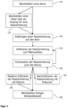
- figure 3 1 schematically shows a flow chart of process variants for the production of a ceramic fiber composite component 100. This begins with the provision 310 of a ceramic core 110, which forms the interior of the finished ceramic composite component 100. Optionally, providing 310 can include additive manufacturing (not shown) of ceramic core 110 .
- a fiber 122 can first be impregnated and provided. This impregnation of the fiber 122 serves as a preliminary stage of a fiber reinforcement 120.
- an impregnated fiber can be wound directly onto the component (wet winding process) or can be used to produce the prepreg.
- a fiber reinforcement 120 (or a prepreg from step 315) is applied to the ceramic core 110.
- This outer fiber reinforcement 120 later serves to reinforce the ceramic core 110.
- the application 320 can be accomplished by various methods, for example wet winding, wet braiding, dry winding, braiding, lamination or the like.
- the fiber reinforcement 120 is infiltrated with a carbonaceous or a polymeric material 125 .
- the fiber reinforcement 120 in particular the fibers 122 contained therein, are wetted, covered, penetrated or otherwise surrounded by the material 125.
- the polymeric material 125 may include polysilazane or a phenolic resin.
- the carbonaceous material may comprise a suspension of carbon black or a slurry containing carbon.
- the infiltration of step 330 can take place in step 315, ie before step 320 of application, for example by using a dip tank with a ceramic precursor through which the fiber 122 is guided.
- the precursor can be a ceramic slip.
- the fiber 122 so impregnated can be applied to the core 110 by wet winding, wet braiding, or laminating previously fabricated prepregs.
- the infiltration can generally take place by means of liquid phase infiltration.
- This can be carried out, for example, as a polymer infiltration and pyrolysis process (PIP), for example using polysilazane as material 125, or as a reactive melt silicon infiltration process (LSI - Liquid Silicon Infiltration), for example using phenolic resin and crosslinking with subsequent pyrolysis and melt infiltration.
- PIP polymer infiltration and pyrolysis process
- LSI - Liquid Silicon Infiltration reactive melt silicon infiltration process
- gas-phase infiltration processes can also be used to build up a carbon or silicon carbide-based matrix.
- the fiber reinforcement 120 is pyrolyzed.
- the effect of heat achieved here can heat not only the fiber reinforcement 120 but optionally also the core 110 .
- a matrix build-up or a matrix conversion (conversion) of the carbonaceous material 125 can thereby be brought about become.
- the material 125 with which the fiber 122 is infiltrated is a polymer or comprises a polymer
- the pyrolyzing in step 340 can also cause the material 125 to be converted at least partially into carbon. In any case, the fiber reinforcement 120 is converted into a ceramic state.
- the component gives the component a very high level of strength, with the matrix material causing a high level of rigidity, but itself being brittle and having a low level of strength, and the fiber contributing to a high level of strength.
- the embedded fiber increases the strength of the matrix material.
- Steps 330 and 340 can also be performed simultaneously, for example in a chemical vapor phase infiltration.
- carbon or silicon carbide is precipitated from a gas, which infiltrates the fiber reinforcement 120 and settles on the fiber.
- the fiber 122 of the fiber reinforcement 120 can either be laid dry on the core 110 or applied in one of the wet-laying processes mentioned above.
- the infiltrating and pyrolyzing step 330 may be repeated until the fiber reinforcement 120 has the desired density.
- the ceramic core 110 can be provided in step 310 in a pre-ceramic state. In this state, the core 110 is dimensionally stable enough for the fiber reinforcement 120 to be applied thereto. During the pyrolyzing in step 340, the core 110 together with the fiber reinforcement 120 can be converted into the ceramic state. This allows heating (and thus expansion) and cooling (and thus contraction) of all components in the same or at least very similar states.
- Another optional step is post-infiltration of the fiber reinforcement 120 in step 350, for example with a precursor.
- a precursor can be a ceramic precursor and/or a polymer.
- the method then returns to step 340, in which the fiber reinforcement 120 is pyrolyzed again. As a result, the porosity of the fiber reinforcement 120 can be reduced.
- step 355 is the reactive infiltration of the fiber reinforcement 120 with molten silicon in step 355.
- This step 355 can also be carried out after a post-infiltration according to step 350 and repeated pyrolysis 340.
- molten silicon on / in the porous carbon matrix of Fiber reinforcement 120 are applied and introduced.
- the carbon can react with the silicon to form silicon carbide.
- This step 355 is particularly suitable for the fused silicon infiltration process.
- the post-infiltration in step 350 can be carried out in a desiccator, autoclave or vacuum bag, for example.
- the reactive infiltration in step 355 can be performed under vacuum or inert gas in silicon furnaces (e.g., resistance heated vacuum graphitic furnace) above the silicon melting point.
- step 360 the finished composite component 100 is provided, which is removed from the infiltration device and/or pyrolysis device, for example.
Abstract
Es wird ein Verfahren zur Herstellung eines keramischen Faserverbundbauteils (100) beschrieben. Das Verfahren umfasst ein Bereitstellen (310) eines keramischen Kerns (110), der das Innere des fertigen keramischen Faserverbundbauteils (100) bildet, und ein Aufbringen (320) einer äußeren Faserarmierung (120) auf den keramischen Kern (110). Gleichzeitig oder anschließend kann das Verfahren ein Infiltrieren (330) der Faserarmierung (120) mit einem kohlenstoffhaltigen oder einem polymeren Material (125), und ein Pyrolysieren (340) der infiltrierten Faserarmierung (120) oder des keramischen Kerns (110) mit der infiltrierten Faserarmierung (120) umfassen. Ferner ist ein Kompositverbundbauteil mit einem keramischen Kern und einer äußeren Faserarmierung, die mit einem pyrolysierten kohlenstoffhaltigen oder polymeren Material infiltriert ist, beschrieben. Das Infiltrieren (315, 330) kann vor dem Aufbringen (320) erfolgen.A method for producing a ceramic fiber composite component (100) is described. The method includes providing (310) a ceramic core (110), which forms the interior of the finished ceramic fiber composite component (100), and applying (320) an outer fiber reinforcement (120) to the ceramic core (110). Simultaneously or subsequently, the method can infiltrate (330) the fiber reinforcement (120) with a carbonaceous or a polymeric material (125), and pyrolyze (340) the infiltrated fiber reinforcement (120) or the ceramic core (110) with the infiltrated fiber reinforcement (120). Furthermore, a composite composite component with a ceramic core and an outer fiber reinforcement, which is infiltrated with a pyrolyzed carbonaceous or polymeric material, is described. The infiltration (315, 330) can take place before the application (320).
Description
Die Erfindung betrifft ein Verfahren zur Herstellung eines keramischen Faserverbundbauteils sowie ein keramisches Faserverbundbauteil. Insbesondere betrifft die Erfindung ein Verfahren zur Herstellung eines keramischen Bauteils, das eine Faserarmierung umfasst, welche von einem kohlenstoffhaltigen oder polymeren Material, das pyrolysiert ist, infiltriert ist. Ferner betrifft die Erfindung ein solches keramisches faserverstärktes Bauteil.The invention relates to a method for producing a ceramic fiber composite component and a ceramic fiber composite component. In particular, the invention relates to a method of manufacturing a ceramic component comprising a fiber reinforcement infiltrated by a carbonaceous or polymeric material that is pyrolyzed. Furthermore, the invention relates to such a ceramic fiber-reinforced component.
Viele Kompositverbundbauteile werden mehrschichtig hergestellt, wobei zwischen den einzelnen Schichten ein Formschluss und/oder Kraftschluss zu erzielen versucht wird. So werden beispielsweise auf Metallrohren Carbonfasern, die in einer passenden Matrix eingebettet sind, angeordnet, um den Metallrohren eine höhere (Berst-) Stabilität zu geben. Andererseits wird auf einen entnehmbaren oder verlorenen Kern ein Kompositmaterial (zum Beispiel ein Prepreg) aufgebracht und ausgehärtet. Anschließend wird der Kern mechanisch, thermisch und/oder chemisch entfernt. Der entfernte Kern kann jedoch meist nicht wieder verwendet werden.Many composite components are manufactured in multiple layers, with attempts being made to achieve a form fit and/or force fit between the individual layers. For example, carbon fibers embedded in a suitable matrix are arranged on metal tubes in order to give the metal tubes greater (bursting) stability. On the other hand, a composite material (e.g. a prepreg) is applied to a removable or lost core and cured. The core is then removed mechanically, thermally and/or chemically. However, the removed core usually cannot be reused.
Vor diesem Hintergrund liegt der vorliegenden Erfindung die Aufgabe zugrunde, ein kostengünstiges und schnelles Verfahren zum Herstellen eines keramischen faserverstärkten Bauteils sowie ein entsprechendes Bauteil, das hohen Belastungen standhält, bereitzustellen.Against this background, the object of the present invention is to provide a cost-effective and quick method for producing a ceramic fiber-reinforced component and a corresponding component that withstands high loads.
Diese Aufgabe wird durch ein Verfahren mit den Merkmalen des Anspruchs 1 sowie ein Bauteil mit den Merkmalen des Anspruchs 13 gelöst.This object is achieved by a method having the features of
Gemäß einem ersten Aspekt zum besseren Verständnis der vorliegenden Offenbarung umfasst ein Verfahren zur Herstellung eines keramischen Faserverbundbauteils ein Bereitstellen eines keramischen Kerns, der das Innere des fertigen keramischen Faserverbundbauteils bildet, und ein Aufbringen einer äußeren Faserarmierung auf den keramischen Kern. Der keramische Kern verbleibt in dem Bauteil, weshalb das übliche Entfernen eines innenliegenden Kerns zum Formen des äußeren Kompositmaterials entfällt. Das Herstellverfahren ist daher schneller und kostengünstiger.According to a first aspect for a better understanding of the present disclosure, a method for producing a ceramic fiber composite component comprises providing a ceramic core, which forms the interior of the finished ceramic fiber composite component, and applying an outer fiber reinforcement to the ceramic core. The ceramic core remains in the component, eliminating the traditional removal of an inner core to form the outer composite material. The manufacturing process is therefore faster and cheaper.
Ferner können aufgrund der Eigenschaften des keramischen Kerns bestimmte Funktionen des Bauteils von dem Kern übernommen werden. So lässt sich der keramische Kern neben der Formgebung für die Faserarmierung auch zur Erhöhung der Bauteilleistung, zum Beispiel durch Steigerung der Steifigkeit oder Festigkeit, als Oxidationsschutz der Faserarmierung und/oder zur Erzielung einer Gasdichtigkeit einsetzen. Ferner kann der Kern mit Hohlräumen versehen werden, wodurch der Kern eine vorgegebene Isolationswirkung hat. Die Hohlräume können optional auch in Form von Kanälen vorliegen, durch die ein Kühlmittel strömen kann, wodurch der Kern eine Kühlfunktion übernehmen kann. Schließlich können auch Sensoren oder andere Bauelemente in den Kern integriert werden, um Messungen direkt im Bauteil vorzunehmen. Diese Funktionalitäten des Kerns lassen sich in Bauteilen, die ausschließlich aus einem faserverstärkten Material, insbesondere Bauteilen mit Langfasern, bestehen, nicht umsetzen.Furthermore, due to the properties of the ceramic core, certain functions of the component can be taken over by the core. In addition to shaping the fiber reinforcement, the ceramic core can also be used to increase component performance, for example by increasing rigidity or strength, to protect the fiber reinforcement from oxidation and/or to achieve gas-tightness. Furthermore, the core can be provided with cavities, as a result of which the core has a predetermined insulating effect. The cavities can optionally also be in the form of channels through which a coolant can flow, as a result of which the core can assume a cooling function. Finally, sensors or other components can also be integrated into the core in order to take measurements directly in the component. These functionalities of the core cannot be implemented in components that consist exclusively of a fiber-reinforced material, in particular components with long fibers.
Das Verfahren umfasst ferner ein Infiltrieren der Faserarmierung mit einem kohlenstoffhaltigen oder einem polymeren Material, und ein Pyrolysieren der infiltrierten Faserarmierung oder des keramischen Kerns mit der infiltrierten Faserarmierung. Mit anderen Worten wird eine Matrix um die Faserarmierung gebildet, die zusammen mit dieser einen keramischen Faserverbundwerkstoff bildet. Dadurch lässt sich ein Bauteil mit hoher Festigkeit herstellen, das die Eigenschaften des keramischen Kerns und des keramischen Faserverbundwerkstoffes vereint.The method further includes infiltrating the fiber reinforcement with a carbonaceous or a polymeric material, and pyrolyzing the infiltrated fiber reinforcement or the ceramic core with the infiltrated fiber reinforcement. In other words, a matrix is formed around the fiber reinforcement, which together with this forms a ceramic fiber composite material. As a result, a high-strength component can be produced that combines the properties of the ceramic core and the ceramic fiber composite material.
In einer Implementierungsvariante kann das Infiltrieren vor dem Aufbringen erfolgen. Mit anderen Worten wird die Faserarmierung mit dem kohlenstoffhaltigen oder polymeren Material versehen, es kann auch von Imprägnierung gesprochen werden, bevor die Faserarmierung auf dem keramischen Kern aufgebracht wird. Die imprägnierte Faserarmierung kann auch als Prepreg bezeichnet werden. Beispielsweise wird eine Faser (insbesondere eine Langfaser als Faser-Roving), die die Faserarmierung bildet, mit einem keramischen Prekursor benetzt und somit infiltriert.In an implementation variant, the infiltration can take place before the application. In other words, the fiber reinforcement is provided with the carbonaceous or polymeric material, one can also speak of impregnation, before the fiber reinforcement is applied to the ceramic core. The impregnated fiber reinforcement can also be referred to as prepreg. For example, a fiber (in particular a long fiber as a fiber roving) that forms the fiber reinforcement is wetted with a ceramic precursor and thus infiltrated.
In einer weiteren Implementierungsvariante kann das Infiltrieren der Fasern für eine Faserarmierung in einem Tauchbecken mit einem keramischen Prekursor erfolgen. Lediglich beispielhaft kann der Prekursor ein keramischer Schlicker sein oder polymerbasiert sein, wie zum Beispiel Polysilazan. Somit kann das Aufbringen der Faserarmierung auf den keramischen Kern als ein Nasswickelverfahren oder Nassflechtverfahren mit der imprägnierten Faserarmierung durchgeführt werden.In a further implementation variant, the fibers for fiber reinforcement can be infiltrated in a dip tank with a ceramic precursor. For example only, the precursor may be a ceramic slurry or polymer-based such as polysilazane. Thus, the application of the fiber reinforcement to the ceramic core can be carried out as a wet winding process or wet braiding process with the impregnated fiber reinforcement.
In einer anderen Implementierungsvariante kann das Pyrolysieren eine Wärmebehandlung der infiltrierten Faserarmierung oder des keramischen Kerns mit der infiltrierten Faserarmierung umfassen. Durch die Wärmebehandlung wird ein Matrixaufbau oder eine Matrixkonvertierung des kohlenstoffhaltigen Materials bewirkt. Handelt es sich bei dem bei der Infiltration eingesetzten Material um ein Polymer, bewirkt die Wärmebehandlung eine Umwandlung des polymeren Materials zu Kohlenstoff. Das Pyrolysieren kann beispielsweise durch Aufheizen der Faserarmierung (und dabei gegebenenfalls auch des keramischen Kerns) auf eine Temperatur zwischen 800 °C und 1600 °C, vorzugsweise zwischen 900 °C und 1200 °C, erfolgen. Die Temperatur kann in Abhängigkeit des zu pyrolysierenden Materials gewählt werden. So kann bei einem Harz (Polymer) eine Carbonisierung zum Beispiel bei ca. 900 °C erfolgen, bei Polisilizan (Polymer) findet eine Pyrolyse zwischen 1000 °C und 1200 °C statt. Bei einem siliziumhaltigen Polymer kann dieses auch mit anderen Bestandteilen in diesem Temperaturbereich reagieren, zum Beispiel Kohlenstoff mit Silizium zu SiC. Soll beispielsweise Stickstoff (N) abgeschieden werden, sind auch Temperaturen von mehr als 1400 °C, zum Beispiel 1600 °C, vorteilhaft. Aufgrund der Reaktionen und der Konvertierung der Matrix bei der hohen Temperatur kann beim Pyrolysieren auch von Keramisierung gesprochen werden, da das Material zur Infiltrierung der Faserarmierung einen keramischen Zustand erreicht.In another implementation variant, the pyrolyzing can include a heat treatment of the infiltrated fiber reinforcement or of the ceramic core with the infiltrated fiber reinforcement. The heat treatment brings about a matrix build-up or a matrix conversion of the carbonaceous material. If the material used in the infiltration is a polymer, the heat treatment causes the polymeric material to be converted to carbon. Pyrolysis can be carried out, for example, by heating the fiber reinforcement (and possibly also the ceramic core) to a temperature between 800.degree. C. and 1600.degree. C., preferably between 900.degree. C. and 1200.degree. The temperature can be chosen depending on the material to be pyrolyzed. For example, a resin (polymer) can carbonize at around 900 °C, while polysilizan (polymer) undergoes pyrolysis between 1000 °C and 1200 °C. In the case of a silicon-containing polymer, this can also react with other components in this temperature range, for example carbon with silicon to form SiC. If, for example, nitrogen (N) is to be separated, temperatures of more than 1400° C., for example 1600° C., are also advantageous. Due to the reactions and the conversion of the matrix at the high temperature, one can also speak of ceramization during pyrolysis, since the material for infiltrating the fiber reinforcement reaches a ceramic state.
In noch einer weiteren Implementierungsvariante kann das Aufbringen der äußeren Faserarmierung ein Bereitstellen einer imprägnierten Faser als Prepreg und ein Aufbringen des Prepregs auf den keramischen Kern umfassen. Dabei kann die imprägnierte Langfaser auf eine Trommel zur Prepreg-Fertigung aufgewickelt werden. Das Aufbringen auf den keramischen Kern mit einem Prepreg erfolgt dann zum Beispiel im Laminierverfahren.In yet another implementation variant, the application of the outer fiber reinforcement can include providing an impregnated fiber as a prepreg and applying the prepreg to the ceramic core. The impregnated long fiber can be wound onto a drum for prepreg production. It is then applied to the ceramic core with a prepreg, for example using a laminating process.
In einer Implementierungsvariante kann das Verfahren ferner ein Nachinfiltrieren der äußeren Faserarmierung mit einem Prekursor umfassen. Der Prekursor kann zum Beispiel ein keramischer oder polymerer Prekursor sein. Ein weiteres Pyrolysieren der nachinfiltrierten Faserarmierung dient zur Materialverdichtung und kann so lange durchgeführt werden, bis die gewünschte maximale Restporosität erreicht ist. Die Restporosität kann beispielsweise nach einem weiteren Pyrolysieren weniger als 5 % betragen.In an implementation variant, the method can also include post-infiltration of the outer fiber reinforcement with a precursor. The precursor can be a ceramic or polymeric precursor, for example. Further pyrolysis of the post-infiltrated fiber reinforcement serves to compact the material and can be carried out until the desired maximum residual porosity is reached. The residual porosity can be less than 5%, for example after further pyrolysis.
Alternativ oder zusätzlich kann das Verfahren ferner ein Nachinfiltrieren der pyrolysierten Faserarmierung mit schmelzflüssigem Silizium umfassen. Dabei kann das Silizium mit dem Kohlenstoff (aus dem pyrolysierten infiltrierten Material oder dem pyrolysierten Polymer) zu Siliziumkarbid reagieren. Aufgrund des schmelzflüssigen Siliziums wird auch von einem flüssigen Siliziuminfiltrationsprozess (Engl.: Liquid Silicon Infiltration - LSI) gesprochen.Alternatively or additionally, the method can also include post-infiltration of the pyrolyzed fiber reinforcement with molten silicon. The silicon can be mixed with the carbon (from the pyrolyzed infiltrated material or the pyrolyzed polymer) to silicon carbide. Due to the molten silicon, it is also referred to as a liquid silicon infiltration process (LSI).
Lediglich beispielhaft kann das Nachinfiltrieren in einem Exsikkator, Autoklaven oder Vakuumsack erfolgen.By way of example only, post-infiltration can take place in a desiccator, autoclave or vacuum bag.
In einer anderen Implementierungsvariante kann das Infiltrieren mit gasförmigen Stoffen erfolgen. Hierbei wird vorzugsweise der Matrixaufbau mittels chemischer Gasphaseninfiltration vorgenommen. Mit anderen Worten wird das kohlenstoffhaltige Material unter Wärmeeinwirkung aus einem Gas abgeschieden, wobei es die Faserarmierung infiltriert und sich auf dem Faserfilament ablegt. Bei dem Gas kann es sich zum Beispiel um Methan, Propan oder ein gesättigt des Trägergas, zum Beispiel durch Verdampfen von Toluol, handeln.In another implementation variant, the infiltration can take place with gaseous substances. In this case, the matrix is preferably built up by means of chemical gas phase infiltration. In other words, the carbonaceous material is thermally deposited from a gas, infiltrating the fiber reinforcement and depositing on the fiber filament. The gas can be, for example, methane, propane or a saturated carrier gas, for example by vaporizing toluene.
Alternativ oder zusätzlich kann in dem Prozess der Gasphaseninfiltration auch Siliziumkarbid aus dem Gas abgeschieden werden und zum Materialaufbau auf die Faserarmierung aufgebracht werden.Alternatively or additionally, silicon carbide can also be separated from the gas in the process of gas phase infiltration and applied to the fiber reinforcement to build up the material.
In einer weiteren Implementierungsvariante kann das Bereitstellen des keramischen Kerns eine additive Fertigung des keramischen Kerns umfassen. Eine additive Fertigung ermöglicht die Formung eines keramischen Kerns, der die Innenstruktur des fertigen Bauteils bildet. Die additive Fertigung ermöglicht jede beliebige Form des Kerns und somit des Bauteils, auch solche, die nicht durch entnehmbare Kerne gebildet werden kann. Ein entnehmbarer Kern wäre zum Beispiel zylindrisch und kann aus dem fertigen Bauteil herausgezogen (entnommen) werden. Durch das additive Fertigen sind Formen des Kerns möglich, die Abzweigungen umfassen, Hohlräume, Vertiefungen, Erhebungen, etc.In a further implementation variant, the provision of the ceramic core can include additive manufacturing of the ceramic core. Additive manufacturing enables the formation of a ceramic core that forms the internal structure of the finished part. Additive manufacturing enables any shape of the core and thus of the component, even those that cannot be formed by removable cores. For example, a removable core would be cylindrical and can be pulled out (removed) from the finished component. Additive manufacturing allows for core shapes that include branches, cavities, depressions, elevations, etc.
In noch einer weiteren Implementierungsvariante kann die additive Fertigung ein selektives Lasersintern, selektives Laserschmelzen, Photopolymerisation, pulverbettbasiertes Schmelzen oder Freistrahlmaterialauftrag eines Grundmaterials umfassen. Bei dem Grundmaterial kann es sich um ein Material handeln, welches durch das additive Fertigungsverfahren in einen keramischen Zustand übergeführt wird. Das Grundmaterial kann pulverförmig oder flüssig vorliegen und Schicht für Schicht den keramischen Kern formen.In yet another implementation variant, the additive manufacturing can include selective laser sintering, selective laser melting, photopolymerization, powder bed-based melting or free jet material application of a base material. The base material can be a material that is converted into a ceramic state by the additive manufacturing process. The base material can be in powder or liquid form and form the ceramic core layer by layer.
Alternativ oder zusätzlich kann die additive Fertigung mit einem Grundmaterial durchgeführt werden, das im vorkeramischen Zustand bleibt. Die additive Fertigung kann ein adhäsives Verfahren umfassen, kann aber ebenso ein Lasersintern oder Laserschmelzen umfassen. Jedoch wird das Grundmaterial nicht in den keramischen Zustand überführt, sondern lediglich miteinander verklebt. Hierbei kann es sich ebenfalls um ein pulverförmiges Material handeln. Der Kern liegt somit als Preform vor und ist noch nicht in dem Materialzustand, wie in dem fertigen Bauteil.Alternatively or additionally, additive manufacturing can be performed with a base material that remains in the pre-ceramic state. Additive manufacturing can include an adhesive process, but can also include laser sintering or include laser melting. However, the base material is not converted into the ceramic state, but only glued together. This can also be a powdery material. The core is therefore available as a preform and is not yet in the same material condition as in the finished component.
Wenn der Kern im vorkeramischen Zustand (Preform) vorliegt, wird das Pyrolysieren und/oder eine Umwandlung des Materials zusammen mit der infiltrierten Faserarmierung auf den keramischen Kern angewandt. Dadurch kann eine Keramisierung des Kerns zusammen mit der Keramisierung der Armierung stattfinden. Dies ermöglicht eine Anbindung der Faserarmierung an den Kern, also ein Stoffschluss zwischen Faserarmierung und Kern.If the core is in the pre-ceramic state (preform), pyrolysis and/or a conversion of the material together with the infiltrated fiber reinforcement is applied to the ceramic core. As a result, ceramization of the core can take place together with ceramization of the reinforcement. This enables the fiber reinforcement to be connected to the core, i.e. a bond between the fiber reinforcement and the core.
In einer anderen Implementierungsvariante kann die Faserarmierung Kohlenstofffasern oder Siliziumkarbid-Fasern umfassen.In another implementation variant, the fiber reinforcement can include carbon fibers or silicon carbide fibers.
In noch einer weiteren Implementierungsvariante kann das polymere Material Polysilazan oder ein Phenolharz umfassen. Polysilazan bildet während des Pyrolysierens Siliziumkarbid als keramische Phase. Ein Phenolharz wird während des Pyrolysierens in porösen, amorphen Kohlenstoff umgewandelt.In yet another implementation variant, the polymeric material may comprise polysilazane or a phenolic resin. Polysilazane forms silicon carbide as a ceramic phase during pyrolysis. A phenolic resin is converted into porous, amorphous carbon during pyrolyzing.
In einer anderen Implementierungsvariante kann das Verfahren ferner ein Aufbringen einer Zwischenschicht oder Zwischenphase auf den keramischen Kern umfassen, bevor die Faserarmierung aufgebracht wird. Die Zwischenphase kann kohlenstoffhaltig sein, oder dem Infiltrat der Faserarmierung entsprechen.In another implementation variant, the method can further comprise applying an intermediate layer or intermediate phase to the ceramic core before the fiber reinforcement is applied. The intermediate phase can contain carbon or correspond to the infiltrate of the fiber reinforcement.
Gemäß einem weiteren Aspekt zum besseren Verständnis der vorliegenden Offenbarung umfasst ein Kompositverbundbauteil einen keramischen Kern, der das Innere des Bauteils bildet, und eine äußere Faserarmierung, die den keramischen Kern umgibt und Kohlenstofffasern oder Siliziumkarbid-Fasern, die eine Faserarchitektur bilden und mit einem pyrolysierten kohlenstoffhaltigen oder polymeren Material infiltriert sind. Das Kompositbauteil kann beispielsweise durch das Verfahren gemäß dem ersten Aspekt oder einer der zugehörigen Implementierungsvarianten hergestellt werden.According to a further aspect for a better understanding of the present disclosure, a composite composite component comprises a ceramic core forming the interior of the component and an outer fibrous reinforcement surrounding the ceramic core and carbon fibers or silicon carbide fibers forming a fibrous architecture and infiltrated with a pyrolyzed carbonaceous or polymeric material. The composite component can be produced, for example, by the method according to the first aspect or one of the associated implementation variants.
Durch die Kombination eines keramischen Kerns mit einer außenliegenden Faserverstärkung (Faserarmierung) kann das Bauteil sowohl die Eigenschaften des keramischen Kerns als auch die der Faserarmierung aufweisen. In einer Faserverstärkung ist es beispielsweise sehr schwierig, Kühlkanäle vorzusehen. Diese müssten als eigenständige Kanäle in die Faserverstärkung integriert werden. Bei dem keramischen Kern können die Kühlmittelkanäle durch Hohlräume in dem keramischen Material gebildet werden.The combination of a ceramic core with an external fiber reinforcement (fiber reinforcement) means that the component can have both the properties of the ceramic core and those of the fiber reinforcement. In a fiber reinforcement, for example, it is very difficult to provide cooling channels. These would have to be integrated into the fiber reinforcement as independent channels. In which ceramic core, the coolant channels can be formed by cavities in the ceramic material.
Zudem kann der Kern, der keramisch ausgebildet ist, gasdicht sein. Dies verhindert, dass Sauerstoff zu der Faserarmierung oder Kühlmittel aus den Kühlkanälen zur Außen- oder Innenwand gelangt. Ist das Kompositbauteil hohen Temperaturen ausgesetzt, könnte die Faser, insbesondere wenn es sich um eine Kohlefaser handelt, im Zusammenwirken mit Sauerstoff Schaden nehmen, beispielsweise oxidieren. Durch den gasdicht hergestellten keramischen Kern wird dies verhindert.In addition, the core, which is ceramic, can be gas-tight. This prevents oxygen from reaching the fiber reinforcement or coolant from the cooling channels to the outer or inner wall. If the composite component is exposed to high temperatures, the fibre, especially if it is a carbon fibre, could be damaged by the interaction with oxygen, for example oxidize. This is prevented by the gas-tight ceramic core.
In einer Implementierungsvariante kann der keramische Kern innenliegende Hohlräume, zu Kanälen verbundene innenliegende Hohlräume und/oder Sensoren umfassen. Der keramische Kern kann somit Funktionen des fertigen Bauteils übernehmen, wie zum Beispiel Isolationseigenschaften durch die Hohlräume, die Führung von Kühlmittel durch die Kanäle bzw. Messungen in dem Bauteil mithilfe von Sensoren, insbesondere die in dem Kern umfassten Sensoren.In an implementation variant, the ceramic core can comprise internal cavities, internal cavities connected to form channels and/or sensors. The ceramic core can thus take over functions of the finished component, such as insulating properties through the cavities, the conduction of coolant through the channels or measurements in the component using sensors, in particular the sensors included in the core.
In einer anderen Implementierungsvariante kann das Kompositbauteil ferner eine Zwischenschicht oder Zwischenphase zwischen dem keramischen Kern und der Faserarmierung umfassen. Die Zwischenschicht oder Zwischenphase kann der Verbesserung des Formschlusses oder Kraftschlusses zwischen Kern und Faserarmierung dienen, beispielsweise durch eine bessere Verbindung sowohl zu dem Kern als auch der Faserarmierung. Ferner ist es möglich, durch eine oder mehrere geeignete Zwischenschichten oder Zwischenphasen thermische Spannungen zwischen Kern und Faserarmierung zu reduzieren. Insbesondere während des Pyrolysierens oder bei der chemischen Gasphasenabscheidung bzw. Infiltration wird sowohl der Kern als auch die Faserarmierung erhitzt und dehnen sich aus, und je nach Implementierungsvariante können die Faserarmierung aber auch der Kern ihren Materialzustand ändern (zum keramischen Zustand übergehen), wodurch bei einer Abkühlung aller Komponenten diese ein unterschiedliches Schrumpfungsverhalten (oder Schwindungsverhalten) aufweisen können. Diese Unterschiede können durch eine oder mehrere Zwischenschichten oder Zwischenphase ausgeglichen werden.In another implementation variant, the composite component can also include an intermediate layer or intermediate phase between the ceramic core and the fiber reinforcement. The intermediate layer or intermediate phase can serve to improve the positive or non-positive connection between the core and the fiber reinforcement, for example through a better connection both to the core and to the fiber reinforcement. Furthermore, it is possible to reduce thermal stresses between core and fiber reinforcement by means of one or more suitable intermediate layers or intermediate phases. In particular, during pyrolysis or during chemical vapor deposition or infiltration, both the core and the fiber reinforcement are heated and expand, and depending on the implementation variant, the fiber reinforcement but also the core can change their material state (transition to the ceramic state), which means that when all the components cool down, they can have different shrinkage behavior (or shrinkage behavior). These differences can be compensated for by one or more intermediate layers or interphases.
Gemäß noch einem weiteren Aspekt zum besseren Verständnis der vorliegenden Offenbarung umfasst ein Verfahren zum Herstellen eines Raketentriebwerksabschnitts ein Bereitstellen mindestens eines Grundstoffs, und ein Herstellen des Raketentriebwerksabschnitts gemäß dem Verfahren des ersten Aspekts. Der bereitgestellte Grundstoff wird mittels additiver Fertigung zu dem keramischen Kern geformt, der die innere Form für die Faserarmierung aber auch den Raketentriebwerksabschnitt bildet.According to yet another aspect for better understanding of the present disclosure, a method for manufacturing a rocket engine section comprises providing at least one raw material, and manufacturing the rocket engine section according to the method of the first aspect. The basic material provided is turned into the ceramic core by means of additive manufacturing molded which forms the internal mold for the fiber armor but also the rocket engine section.
Beim Herstellen des Raketentriebwerksabschnitts, beispielsweise eines Brennkammerkörpers, und insbesondere des keramischen Kerns, können Kühlmittelkanäle in dem keramischen Kern während und mittels der additiven Fertigung gebildet werden. Diese Kühlmittelkanäle dienen in dem fertigen Brennkammerkörper zur Durchleitung eines Kühlmittels, um die Innenseite des Brennkammerkörpers, die bei der Verbrennung erhitzt wird, zu kühlen.In manufacturing the rocket engine portion, such as a combustor body, and particularly the ceramic core, coolant passages may be formed in the ceramic core during and by means of additive manufacturing. In the finished combustion chamber body, these coolant channels are used for conducting a coolant to cool the inside of the combustion chamber body, which is heated during combustion.
Insbesondere durch eine additive Fertigung (auch als 3D-Druck, Binder Jetting, selektives Laserschmelzen und -sintern, Photopolymerisation, FreistrahlMaterialauftrag, oder Additive Layer Manufacturing - ALM bekannt) kann der keramische Kern schichtweise mit den darin ausgebildeten Kanälen und/oder integrierten Sensoren oder anderen Komponenten hergestellt werden. Dadurch lassen sich sämtliche Hohlräume, zum Beispiel das Innere eines Kanals sowie anderweitige Hohlräume, in einfacher, schneller und kostengünstiger Weise und in beliebiger Form herstellen.In particular, additive manufacturing (also known as 3D printing, binder jetting, selective laser melting and sintering, photopolymerization, free-jet material application, or Additive Layer Manufacturing - ALM) can be used to produce the ceramic core in layers with the channels and/or integrated sensors or other components formed therein. As a result, all cavities, for example the inside of a channel and other cavities, can be produced in a simple, quick and cost-effective manner and in any shape.
Bei dem Grundstoff kann es sich um einen pulverförmigen Grundstoff handeln. Ebenso ist es möglich, einen flüssigen Grundstoff zu verwenden. In beiden Fällen kann durch Energieeintrag, beispielsweise mittels Laser, der Grundstoff zu einer festen Struktur verbunden werden, die in der Lage ist, die Faserarmierung aufzunehmen und dabei ihre Form beizubehalten. Alternativ kann der Grundstoff auch in einem Binder-Jetting-Verfahren oder jedem beliebigen schlicker- oder pulverbettbasierten Verfahren verarbeitet werden.The base material can be a powdered base material. It is also possible to use a liquid base. In both cases, energy input, for example by means of a laser, can be used to connect the base material to form a solid structure that is able to accommodate the fiber reinforcement while retaining its shape. Alternatively, the base material can also be processed in a binder jetting process or any slip or powder bed-based process.
Gemäß einem anderen Aspekt zum besseren Verständnis der vorliegenden Offenbarung umfasst ein Raketentriebwerk ein Bauteil gemäß dem zweiten Aspekt oder einer der dazu beschriebenen Implementierungsvarianten.According to another aspect for a better understanding of the present disclosure, a rocket engine comprises a component according to the second aspect or one of the implementation variants described therefor.
Die oben beschriebenen Aspekte und Implementierungsvarianten können selbstverständlich kombiniert werden, ohne dass dies explizit beschrieben ist. Jede der beschriebenen Implementierungsvarianten ist somit optional zu jeder Implementierungsvariante oder bereits Kombinationen davon zu sehen. Die vorliegende Offenbarung ist somit nicht auf die einzelnen Ausgestaltungen und Varianten in der beschriebenen Reihenfolge oder einer bestimmten Kombination der Aspekte und Implementierungsvarianten beschränkt.The aspects and implementation variants described above can of course be combined without this being explicitly described. Each of the implementation variants described is therefore optional for each implementation variant or already combinations thereof. The present disclosure is therefore not limited to the individual configurations and variants in the order described or to a specific combination of aspects and implementation variants.
Bevorzugte Ausführungsformen der Erfindung werden nun anhand der beigefügten schematischen Zeichnungen näher erläutert, wobei
Figur 1- schematisch eine perspektivische, teilweise aufgeschnittene Ansicht eines Raketentriebwerksabschnitts zeigt;
- Figur 2
- schematisch ein Bauteil in Form einer Rohrverzweigung zeigt; und
- Figur 3
- schematisch ein Ablaufdiagramm eines Verfahrens zur Herstellung eines keramischen Faserverbundbauteils zeigt.
- figure 1
- Figure 12 shows schematically a perspective, partially cut-away view of a rocket engine section;
- figure 2
- shows schematically a component in the form of a manifold; and
- figure 3
- schematically shows a flowchart of a method for producing a ceramic fiber composite component.
Die additive Fertigung bietet den Vorteil, in dem Kern 110 Hohlräume vorzusehen, beispielsweise Kanäle 112. Diese Kanäle 112 können als Kühlmittelkanäle verwendet werden und sind bereits in dem Verbundbauteil 100 integriert. Ebenso können in Hohlräumen 112 oder direkt in dem Material des Kerns 110 Sensoren 114 oder andere Komponenten integriert werden.Additive manufacturing offers the advantage of providing cavities in the
Der keramische Kern 110 ist von einer äußeren Faserarmierung 120 umgeben. Die Faserarmierung 120 bietet eine hohe Festigkeit für den keramischen Kern 110, sodass der Kern 110 dünner ausgestaltet sein kann. Die Faserarmierung 120 kann Fasern 122 (
Um einen besseren Halt (Verbund) zwischen dem Kern 110 und der Faserarmierung 120 zu gewährleisten, kann eine Zwischenschicht oder Zwischenphase 130 zwischen dem keramischen Kern 110 und der Faserarmierung 120 vorgesehen sein.In order to ensure a better hold (bond) between the core 110 and the
Bei üblichen Raketentriebwerksbauteilen muss ein keramischer Kern viel stärker ausgestaltet sein, um den Belastungen während des Betriebs des Raketentriebwerks standzuhalten. Die hierfür notwendige Festigkeit kann jedoch durch die Faserarmierung 120, insbesondere in Kombination mit dem Matrixmaterial 125, gewährleistet werden. Somit kann der keramische Kern 110 deutlich dünner ausgestaltet sein, während das Raketentriebwerksbauteil die gleiche Festigkeit aufweist. Dadurch kann das Raketentriebwerksbauteil leichter und kostengünstiger hergestellt werden.In conventional rocket engine components, a ceramic core must be made much stronger to withstand the stresses during operation of the rocket engine to withstand. However, the strength required for this can be ensured by the
Der hier dargestellte Rohrabzweig hingegen weist einen keramischen Kern 110 auf, der beispielsweise durch ein additives Fertigungsverfahren entsprechend der notwendigen und gewünschten Form gebaut wird. Auf den Kern 110 wird eine äußere Faserarmierung 120 aufgebracht, die zusammen mit dem Matrixwerkstoff eine hohe Festigkeit und Beständigkeit erlangt. Die Verwendung eines verlorenen Kerns ist für die Herstellung nicht notwendig. Ein solches Verbundbauteil 100 weist nicht nur eine sehr hohe Festigkeit auf, sondern ist auch leichter als herkömmliche Rohre und kann zudem eine Gasdichtigkeit aufweisen.The branch pipe shown here, on the other hand, has a
Auch in diesem Verbundbauteil 100 können Sensoren 114 in den Kern 110 integriert werden, um Messungen direkt im Rohrabzweig vorzunehmen. Die Faserarmierung 120 ist in einem Ausschnitt detaillierter schematisch dargestellt. Die Faserarmierung 120 weist eine Vielzahl von Fasern 122 auf, die auf den Kern 110 gewickelt, geflochten und/oder als Prepreg laminiert werden können. Der Kern 110 dient somit als Halteform für die Faserarmierung 120. Die Faserarmierung 120 kann ferner mit einem Material 125 infiltriert werden, dass kohlenstoffhaltig ist oder ein Polymer umfasst. Durch eine anschließende Pyrolyse und/oder Konvertierung des Matrixwerkstoffs wird die Faserarmierung 120 keramisch, wodurch das Verbundbauteil 100 eine sehr hohe Festigkeit erlangt.
In einem weiteren optionalen Schritt 315 kann zunächst eine Faser 122 imprägniert und bereitgestellt werden. Diese Imprägnierung der Faser 122 dient als Vorstufe einer Faserarmierung 120. Zum Beispiel kann eine imprägnierte Faser direkt auf das Bauteil gewickelt werden (Nasswickelverfahren) oder zur Prepregherstellung verwendet werden.In a further
In einem weiteren Schritt 320 wird eine Faserarmierung 120 (oder ein Prepreg aus Schritt 315) auf den keramischen Kern 110 aufgebracht. Diese äußere Faserarmierung 120 dient später als Verstärkung des keramischen Kerns 110. Das Aufbringen 320 kann durch verschiedene Verfahren bewerkstelligt werden, zum Beispiel Nasswickeln, Nassflechten, Trockenwickeln, -flechten, Laminieren o. ä.In a
In dem Schritt 330 wird die Faserarmierung 120 mit einem kohlenstoffhaltigen oder einem polymeren Material 125 infiltriert. Die Faserarmierung 120, insbesondere die darin enthaltenen Fasern 122, werden von dem Material 125 benetzt, belegt, durchdrungen oder anderweitig umgeben. Das polymere Material 125 kann Polysilazan oder ein Phenolharz umfassen. Das kohlenstoffhaltige Material kann eine Rußsuspension oder einen kohlenstoffhaltigen Schlicker umfassen.In
Gemäß einer Option kann das Infiltrieren des Schritts 330 in dem Schritt 315, also vor dem Schritt 320 des Aufbringens, erfolgen, beispielsweise durch Einsatz eines Tauchbeckens mit einem keramischen Prekursor, durch den die Faser 122 geführt wird. Bei dem Prekursor kann es sich um einen keramischen Schlicker handeln. Die so imprägnierte Faser 122 kann durch Nasswickeln, Nassflechten oder Laminieren von zuvor gefertigten Prepregs auf den Kern 110 aufgebracht werden.According to one option, the infiltration of
Das Infiltrieren kann generell mittels Flüssigphaseninfiltration erfolgen. Diese kann beispielsweise als Polymerinfiltration- und Pyrolyseprozess (PIP), zum Beispiel unter Verwendung von Polysilazan als Material 125, oder als reaktiver Schmelzsiliziuminfiltrationsprozess (LSI - Liquid Silicon Infiltration), zum Beispiel unter Verwendung von Phenolharz und Vernetzung mit anschließender Pyrolyse und Schmelzinfiltration, durchgeführt werden. Neben den Flüssigphaseninfiltrationen können auch Gasphaseninfiltrationsverfahren für den Aufbau einer kohlenstoff- oder siliziumkarbidbasierten Matrix angewandt werden.The infiltration can generally take place by means of liquid phase infiltration. This can be carried out, for example, as a polymer infiltration and pyrolysis process (PIP), for example using polysilazane as
Anschließend wird in Schritt 340 die Faserarmierung 120 pyrolysiert. Die hierbei erzielte Wärmeeinwirkung kann nicht nur die Faserarmierung 120 sondern optional auch den Kern 110 erhitzen. Dabei kann ein Matrixaufbau oder eine Matrixkonvertierung (-umwandlung) des kohlenstoffhaltigen Materials 125 bewirkt werden. Ist das Material 125, mit dem die Faser 122 infiltriert ist, ein Polymer oder umfasst ein Polymer, kann das Pyrolysieren in Schritt 340 auch eine Umwandlung des Materials 125 zumindest teilweise zu Kohlenstoff bewirken. In jedem Fall wird die Faserarmierung 120 in einen keramischen Zustand überführt. Dadurch erlangt das Bauteil eine sehr hohe Festigkeit, wobei der Matrixwerkstoff eine hohe Steifigkeit bedingt, selbst aber spröde ist und eine geringe Festigkeit aufweist, und die Faser eine hohe Festigkeit beiträgt. Mit anderen Worten führt die eingebettete Faser zur Festigkeitssteigerung des Matrixmaterials.Subsequently, in
Die Schritte 330 und 340 können auch gleichzeitig durchgeführt werden, beispielsweise in einer chemischen Gasphaseninfiltration. Dabei wird bei einer hohen Temperatur Kohlenstoff oder Siliziumkarbid aus einem Gas ausgeschieden, der/das die Faserarmierung 120 infiltriert und sich auf die Faser legt. Hierbei kann die Faser 122 der Faserarmierung 120 sowohl trocken auf den Kern 110 gelegt werden als auch in einem der oben genannten Nasslegeverfahren aufgebracht werden.
In jedem Fall kann der Schritt 330 des Infiltrierens und des Pyrolysierens (Schritt 340) wiederholt werden, bis die Faserarmierung 120 die gewünschte Dichteaufweist.In either case, the infiltrating and pyrolyzing step 330 (step 340) may be repeated until the
Gemäß einer weiteren Option, und vorzugsweise in Kombination mit der chemischen Gasphaseninfiltration, kann der keramische Kern 110 in einem vorkeramischen Zustand in Schritt 310 bereitgestellt werden. In diesem Zustand ist der Kern 110 formstabil genug, um die Faserarmierung 120 darauf aufzubringen. Während des Pyrolysierens in Schritt 340 kann der Kern 110 zusammen mit der Faserarmierung 120 in den keramischen Zustand überführt werden. Dies ermöglicht eine Erhitzung (und somit Ausdehnung) und Abkühlung (und somit Zusammenziehen) aller Komponenten in den gleichen oder zumindest sehr ähnlichen Zuständen.According to another option, and preferably in combination with chemical vapor phase infiltration, the
Ein weiterer optionaler Schritt ist ein Nachinfiltrieren der Faserarmierung 120 in Schritt 350, beispielsweise mit einem Prekursor. Insbesondere kann es sich um einen keramischen Prekursor und/oder um ein Polymer handeln. Anschließend geht das Verfahren zu dem Schritt 340 zurück, in dem die Faserarmierung 120 erneut pyrolysiert wird. Dadurch kann die Porosität der Faserarmierung 120 reduziert werden.Another optional step is post-infiltration of the
Ein ebenfalls möglicher Schritt ist die reaktive Infiltration der Faserarmierung 120 mit schmelzflüssigem Silizium in Schritt 355. Dieser Schritt 355 kann auch nach einer Nachinfiltrierung gemäß Schritt 350 und wiederholter Pyrolyse 340 erfolgen. Zum Beispiel kann schmelzflüssiges Silizium auf/in die poröse Kohlenstoffmatrix der Faserarmierung 120 aufgebracht und eingebracht werden. Dabei kann der Kohlenstoff mit dem Silizium zu Siliziumkarbid reagieren. Dieser Schritt 355 eignet sich insbesondere für den Schmelzsiliziuminfiltrationsprozess.Another possible step is the reactive infiltration of the
Das Nachinfiltrieren in Schritt 350 kann beispielsweise in einem Exsikkator, Autoklaven oder Vakuumsack durchgeführt werden. Ferner kann die reaktive Infiltration in Schritt 355 unter Vakuum oder Inertgases in Siliziumöfen (zum Beispiel widerstandsbeheizter, grafitischer Vakuumofen) oberhalb des Siliziumschmelzpunktes durchgeführt werden.The post-infiltration in
Schließlich wird in Schritt 360 das fertige Kompositbauteil 100 bereitgestellt, das beispielsweise aus der Infiltriervorrichtung und/oder Pyrolysevorrichtung entnommen wird.Finally, in
Die hier beschriebenen Ausführungsformen sind lediglich beispielhaft und dienen nur der Erläuterung der vorliegenden Erfindung.The embodiments described herein are merely exemplary and are only intended to explain the present invention.
Claims (15)
wobei die additive Fertigung mit einem Grundmaterial durchgeführt wird, das im vorkeramischen Zustand bleibt.Method according to claim 9, wherein the additive manufacturing comprises a selective laser sintering, selective laser melting, photopolymerization, powder bed-based melting or free jet material application of a base material, or
where additive manufacturing is performed with a base material that remains in the pre-ceramic state.
eine Zwischenphase (130) zwischen dem keramischen Kern (110) und der Faserarmierung (120).The composite component (100) according to claim 13 or 14, further comprising:
an interphase (130) between the ceramic core (110) and the fiber reinforcement (120).
Priority Applications (1)
| Application Number | Priority Date | Filing Date | Title |
|---|---|---|---|
| EP22152183.4A EP4215359A1 (en) | 2022-01-19 | 2022-01-19 | A ceramic fibre composite component and method for producing a ceramic fibre composite component |
Applications Claiming Priority (1)
| Application Number | Priority Date | Filing Date | Title |
|---|---|---|---|
| EP22152183.4A EP4215359A1 (en) | 2022-01-19 | 2022-01-19 | A ceramic fibre composite component and method for producing a ceramic fibre composite component |
Publications (1)
| Publication Number | Publication Date |
|---|---|
| EP4215359A1 true EP4215359A1 (en) | 2023-07-26 |
Family
ID=79730139
Family Applications (1)
| Application Number | Title | Priority Date | Filing Date |
|---|---|---|---|
| EP22152183.4A Pending EP4215359A1 (en) | 2022-01-19 | 2022-01-19 | A ceramic fibre composite component and method for producing a ceramic fibre composite component |
Country Status (1)
| Country | Link |
|---|---|
| EP (1) | EP4215359A1 (en) |
Citations (4)
| Publication number | Priority date | Publication date | Assignee | Title |
|---|---|---|---|---|
| US5494867A (en) * | 1991-09-24 | 1996-02-27 | Southwest Research Institute | Method for making fiber-reinforced silicon nitride composites |
| US20130167374A1 (en) * | 2011-12-29 | 2013-07-04 | General Electric Company | Process of producing ceramic matrix composites and ceramic matrix composites formed thereby |
| DE102019215664A1 (en) * | 2019-10-11 | 2021-04-15 | Sgl Carbon Se | Fiber composite components |
| US20210230071A1 (en) * | 2017-04-19 | 2021-07-29 | Rolls-Royce High Temperature Composites Inc. | Method to process a ceramic matrix composite (cmc) with a protective ceramic coating |
-
2022
- 2022-01-19 EP EP22152183.4A patent/EP4215359A1/en active Pending
Patent Citations (4)
| Publication number | Priority date | Publication date | Assignee | Title |
|---|---|---|---|---|
| US5494867A (en) * | 1991-09-24 | 1996-02-27 | Southwest Research Institute | Method for making fiber-reinforced silicon nitride composites |
| US20130167374A1 (en) * | 2011-12-29 | 2013-07-04 | General Electric Company | Process of producing ceramic matrix composites and ceramic matrix composites formed thereby |
| US20210230071A1 (en) * | 2017-04-19 | 2021-07-29 | Rolls-Royce High Temperature Composites Inc. | Method to process a ceramic matrix composite (cmc) with a protective ceramic coating |
| DE102019215664A1 (en) * | 2019-10-11 | 2021-04-15 | Sgl Carbon Se | Fiber composite components |
Similar Documents
| Publication | Publication Date | Title |
|---|---|---|
| EP0927299B1 (en) | Combustion chamber and method for producing a combustion chamber | |
| US4847063A (en) | Hollow composite body having an axis of symmetry | |
| EP0864548B1 (en) | Graphite short fibre reinforced silicon carbide body | |
| DE102004009264B4 (en) | Preparation of a preform by reinforcing a fibrous structure and / or joining fibrous structures together and use in the manufacture of composite parts | |
| DE102004009262B4 (en) | Method for producing a multiply perforated part made of a composite material with ceramic matrix | |
| DE10208991B4 (en) | Ceramic composites with unidirectional orientation of the reinforcing fibers, process for their preparation and their use | |
| EP1154970A1 (en) | Fibre-reinforced ceramic body and method for producing same | |
| WO1999041069A1 (en) | Method for producing a fibre composite | |
| DE10126926B4 (en) | Internal combustion chamber of a ceramic composite material and method of manufacture | |
| EP1748464B1 (en) | Rotary anode and method of fabrication of a heat sink of a rotary anode | |
| DE19861035C2 (en) | Fiber composite material and process for its production | |
| DE10164627C1 (en) | Production of hollow bodies made from fiber-reinforced ceramic materials used in the production of brake and clutch disks comprises forming molding cores | |
| DE3131059A1 (en) | Process for the preparation of carbon fibre-reinforced carbon composite materials | |
| DE102010055248B4 (en) | Method and device for producing a ceramic composite material | |
| DE102015221111A1 (en) | Carbon fiber reinforced carbide ceramic composite component | |
| EP1547992B1 (en) | Process for producing a fibre reinforced composite material and the fibre reinforced composite material | |
| DE102015201119B4 (en) | Production process of ceramic matrix semi-finished products | |
| EP4215359A1 (en) | A ceramic fibre composite component and method for producing a ceramic fibre composite component | |
| EP2118039A1 (en) | Method for producing a fiber-reinforced carbide ceramic component and a carbide ceramic component | |
| DE10230231B4 (en) | Multilayer composite material | |
| DE19815308C2 (en) | Process for the production of reinforcing fibers or bundles of reinforcing fibers, fibers or bundles thus produced and their use | |
| EP2182198B1 (en) | Pressure container for high-temperature use and a method for production of same | |
| DE4301396C2 (en) | Process for the production of porous fiber components | |
| DE102021129747A1 (en) | Fiber ceramic nozzle, use of a fiber ceramic nozzle and method of manufacturing a fiber ceramic nozzle | |
| WO2023217360A1 (en) | Method for producing a preform, preform, method for forming a composite fibre component and composite fibre component |
Legal Events
| Date | Code | Title | Description |
|---|---|---|---|
| PUAI | Public reference made under article 153(3) epc to a published international application that has entered the european phase |
Free format text: ORIGINAL CODE: 0009012 |
|
| STAA | Information on the status of an ep patent application or granted ep patent |
Free format text: STATUS: REQUEST FOR EXAMINATION WAS MADE |
|
| 17P | Request for examination filed |
Effective date: 20220119 |
|
| AK | Designated contracting states |
Kind code of ref document: A1 Designated state(s): AL AT BE BG CH CY CZ DE DK EE ES FI FR GB GR HR HU IE IS IT LI LT LU LV MC MK MT NL NO PL PT RO RS SE SI SK SM TR |